EP3360200B1 - Hf-übertragungsstrecke in einem hausgerät - Google Patents
Hf-übertragungsstrecke in einem hausgerät Download PDFInfo
- Publication number
- EP3360200B1 EP3360200B1 EP16781706.3A EP16781706A EP3360200B1 EP 3360200 B1 EP3360200 B1 EP 3360200B1 EP 16781706 A EP16781706 A EP 16781706A EP 3360200 B1 EP3360200 B1 EP 3360200B1
- Authority
- EP
- European Patent Office
- Prior art keywords
- antenna
- housing
- waveguide structure
- electromagnetic signal
- household appliance
- Prior art date
- Legal status (The legal status is an assumption and is not a legal conclusion. Google has not performed a legal analysis and makes no representation as to the accuracy of the status listed.)
- Active
Links
Images


Classifications
-
- H—ELECTRICITY
- H01—ELECTRIC ELEMENTS
- H01Q—ANTENNAS, i.e. RADIO AERIALS
- H01Q1/00—Details of, or arrangements associated with, antennas
- H01Q1/44—Details of, or arrangements associated with, antennas using equipment having another main function to serve additionally as an antenna, e.g. means for giving an antenna an aesthetic aspect
-
- H—ELECTRICITY
- H01—ELECTRIC ELEMENTS
- H01Q—ANTENNAS, i.e. RADIO AERIALS
- H01Q1/00—Details of, or arrangements associated with, antennas
- H01Q1/007—Details of, or arrangements associated with, antennas specially adapted for indoor communication
-
- H—ELECTRICITY
- H01—ELECTRIC ELEMENTS
- H01Q—ANTENNAS, i.e. RADIO AERIALS
- H01Q1/00—Details of, or arrangements associated with, antennas
- H01Q1/12—Supports; Mounting means
- H01Q1/22—Supports; Mounting means by structural association with other equipment or articles
-
- F—MECHANICAL ENGINEERING; LIGHTING; HEATING; WEAPONS; BLASTING
- F24—HEATING; RANGES; VENTILATING
- F24C—DOMESTIC STOVES OR RANGES ; DETAILS OF DOMESTIC STOVES OR RANGES, OF GENERAL APPLICATION
- F24C7/00—Stoves or ranges heated by electric energy
- F24C7/08—Arrangement or mounting of control or safety devices
- F24C7/082—Arrangement or mounting of control or safety devices on ranges, e.g. control panels, illumination
- F24C7/086—Arrangement or mounting of control or safety devices on ranges, e.g. control panels, illumination touch control
-
- F—MECHANICAL ENGINEERING; LIGHTING; HEATING; WEAPONS; BLASTING
- F25—REFRIGERATION OR COOLING; COMBINED HEATING AND REFRIGERATION SYSTEMS; HEAT PUMP SYSTEMS; MANUFACTURE OR STORAGE OF ICE; LIQUEFACTION SOLIDIFICATION OF GASES
- F25D—REFRIGERATORS; COLD ROOMS; ICE-BOXES; COOLING OR FREEZING APPARATUS NOT OTHERWISE PROVIDED FOR
- F25D2400/00—General features of, or devices for refrigerators, cold rooms, ice-boxes, or for cooling or freezing apparatus not covered by any other subclass
- F25D2400/36—Visual displays
- F25D2400/361—Interactive visual displays
-
- F—MECHANICAL ENGINEERING; LIGHTING; HEATING; WEAPONS; BLASTING
- F25—REFRIGERATION OR COOLING; COMBINED HEATING AND REFRIGERATION SYSTEMS; HEAT PUMP SYSTEMS; MANUFACTURE OR STORAGE OF ICE; LIQUEFACTION SOLIDIFICATION OF GASES
- F25D—REFRIGERATORS; COLD ROOMS; ICE-BOXES; COOLING OR FREEZING APPARATUS NOT OTHERWISE PROVIDED FOR
- F25D29/00—Arrangement or mounting of control or safety devices
-
- H—ELECTRICITY
- H01—ELECTRIC ELEMENTS
- H01Q—ANTENNAS, i.e. RADIO AERIALS
- H01Q1/00—Details of, or arrangements associated with, antennas
- H01Q1/36—Structural form of radiating elements, e.g. cone, spiral, umbrella; Particular materials used therewith
-
- H—ELECTRICITY
- H01—ELECTRIC ELEMENTS
- H01Q—ANTENNAS, i.e. RADIO AERIALS
- H01Q15/00—Devices for reflection, refraction, diffraction or polarisation of waves radiated from an antenna, e.g. quasi-optical devices
- H01Q15/0006—Devices acting selectively as reflecting surface, as diffracting or as refracting device, e.g. frequency filtering or angular spatial filtering devices
- H01Q15/0086—Devices acting selectively as reflecting surface, as diffracting or as refracting device, e.g. frequency filtering or angular spatial filtering devices said selective devices having materials with a synthesized negative refractive index, e.g. metamaterials or left-handed materials
Definitions
- the invention relates to a domestic appliance with a communication unit.
- the household appliance can comprise an HF transmission path made up of independent waveguide structures.
- Devices or electrical devices such as household appliances (e.g. washing machines, tumble dryers, dishwashers, ovens, refrigerators, etc.) often have a metallic housing, which is shielded for HF (high frequency) rays, for reasons of stability. As a result, it is usually difficult to provide wireless communication capabilities (e.g. WLAN, Bluetooth, GPS, UMTS, LTE, etc.) in such devices.
- wireless communication capabilities e.g. WLAN, Bluetooth, GPS, UMTS, LTE, etc.
- Such devices are for example in the JP 2014 209053 A , the CN 103 712 3406 A , the US 2009/193823 A1 or the US 2012/329524 A1 disclosed.
- the present document deals with the technical task of providing wireless communication capabilities in devices, in particular in domestic appliances, which have a shielding housing, in a cost-efficient and reliable manner.
- the device can comprise or correspond to a domestic appliance, in particular a domestic appliance such as a washing machine, a tumble dryer, a dishwasher, an oven or a refrigerator.
- a domestic appliance such as a washing machine, a tumble dryer, a dishwasher, an oven or a refrigerator.
- the device comprises a housing with a plurality of housing walls.
- One or more (possibly all) housing walls can comprise an electrically conductive material (for example a metal).
- the housing can thus have shielding properties for electromagnetic waves (in particular in the range from 30 MHz to 300 GHz).
- the device further comprises a communication unit (also referred to as communication module in this document) and an external antenna, which are set up to receive or transmit an electromagnetic signal.
- the electromagnetic signal can have a frequency in the above-mentioned Cover frequency range from 30MHz to 300GHz.
- the electromagnetic signal can e.g. include a Bluetooth signal or a WiFi signal.
- the electromagnetic signal can correspond to one of the frequency band standards IEEE 802.11 or IEEE 802.15.1.
- the device can include a touch-sensitive screen that enables a user of the device to input control instructions to the device.
- a touch-sensitive screen that enables a user of the device to input control instructions to the device.
- Such a screen is typically arranged at a location on the housing that is easily accessible (for the user) (in particular on an outer wall of the housing).
- the device further comprises a communication unit and an external antenna which are set up to receive or transmit an electromagnetic signal.
- the communication unit can receive or send an electromagnetic signal directly or indirectly via the external antenna.
- the external antenna can correspond to a module antenna of the communication unit which is directly connected to the communication unit.
- the external antenna of a second antenna can correspond to a waveguide structure described in this document.
- the external antenna can be arranged in or on the touch-sensitive screen in such a way that an electromagnetic signal can be sent to a receiver outside the housing or received by a transmitter outside the housing by means of the external antenna. It can thus be achieved that the external antenna can send the electromagnetic signal in a reliable (ie as undamped) manner to an external communication partner or receive it from this.
- a reliable ie as undamped
- the communication unit can have a module antenna.
- the communication unit and the module antenna can be arranged in the housing (ie in the interior of the housing) so that communication between the communication unit and a communication partner (ie a transmitter or receiver) is possible due to the arrangement of the communication unit and the module antenna. outside the housing of the device is made difficult (in particular due to a shielding effect of the housing).
- the device can further comprise at least one waveguide structure with a first antenna and a second antenna.
- the waveguide structure is at least partially arranged in the housing of the device.
- the waveguide structure is set up to receive an electromagnetic signal transmitted by the module antenna by means of the first antenna and to transmit it (again) by means of the second antenna.
- the second antenna can correspond to the external antenna.
- the waveguide structure is set up to receive an electromagnetic signal by means of the second antenna and to send it to the module antenna by means of the first antenna.
- at least the first antenna is typically arranged in the housing of the device.
- the waveguide structure is thus set up to forward an electromagnetic signal within the housing of the device.
- the waveguide structure is preferably a passive structure (without an electrical power supply), which is thus provided in a particularly cost-effective manner.
- the second antenna (in particular the external antenna) can be arranged such that an electromagnetic signal can be sent to a receiver outside the housing or received by a transmitter outside the housing by means of the second antenna.
- the second antenna can optionally be arranged outside the housing of the device.
- the second antenna can be arranged for this purpose at a point on the housing at which the housing (compared to another point on the housing) has a relatively high degree of transmission for the electromagnetic signal (e.g. a degree of transmission of 50%, 70%, 90% or more).
- the waveguide structure can comprise an electrically conductive conductor track which is set up to transmit the electromagnetic signal between the first antenna and the second antenna.
- the electromagnetic signal can be conducted via the conductor track from the first antenna inside the housing to the second antenna outside the housing (or vice versa).
- the communication unit can thus communicate efficiently with an external communication partner outside the housing (e.g. with a WLAN access point).
- the housing can comprise a (first) wall with an electrically conductive material (e.g. metal).
- the waveguide structure can have a dielectric layer on which the conductor track is arranged.
- the dielectric layer can serve as a carrier layer for the conductor track.
- the waveguide structure can be arranged on the first wall in such a way that the dielectric layer isolates the conductor track from the first wall.
- the waveguide structure can have an adhesive layer with which the dielectric layer can be adhered to the first wall.
- an electrically conductive (first) wall of the housing can be used in an efficient manner as a ground for a strip conductor (in English “microstrip”).
- the strip conductor thus created is designed to transmit the electromagnetic signal with relatively low losses between the first antenna and the second antenna.
- the waveguide structure can be designed such that the electromagnetic signal is transmitted between the first antenna and the second antenna by electromagnetic coupling, in particular by resonant coupling, of the first antenna and the second antenna.
- the first antenna and the second antenna can be constructed in such a way that the first antenna and the second antenna have a common resonance frequency.
- the first antenna and the second antenna can be constructed identically.
- the use of resonantly coupled antennas enables relatively loss-free transmission of the electromagnetic signal between the first and the second antenna.
- the first antenna of the waveguide structure and the module antenna can also be coupled via a resonant, electromagnetic coupling in order to enable the electromagnetic signal to be transmitted with as little loss as possible.
- the device may include a variety of waveguide structures.
- the waveguide structures are arranged in such a way that in each case a second antenna of a first waveguide structure is coupled (resonantly) to a first antenna of an adjacent second waveguide structure.
- the plurality of waveguide structures can form a path for the electromagnetic signal from the module antenna out of the housing, or from outside the housing to the module antenna.
- the first antenna of a first waveguide structure can be coupled (resonantly) on the path to the module antenna.
- the second antenna of a last waveguide structure on the path can enable a radio connection with a communication partner outside the housing.
- the waveguide structure may have a support layer (e.g. comprising the dielectric layer).
- the first antenna and the second antenna can be printed on the carrier layer.
- a conductor track of the waveguide structure can also be printed on the carrier layer.
- the waveguide structure can have an adhesive layer with which the (printed) waveguide structure can be adhered to a wall of the housing. This enables the waveguide structure to be installed efficiently in the housing of the device.
- the touch-sensitive screen typically comprises electrically conductive structures which are set up to detect a touch of the screen.
- electrically conductive structures which are set up to detect a touch of the screen.
- on the touch screen (Triangular) conductor tracks can be arranged in order to detect the position of a touch on the screen.
- the second antenna can comprise at least a part of the electrically conductive structures. In other words, the second antenna can be at least partially integrated into the electrically conductive structures of the screen. This enables a particularly cost-effective and space-effective provision of wireless communication capabilities in a device.
- the electrically conductive structures at least partially comprise a metamaterial which gives the electrically conductive structures the property of an antenna.
- the metamaterial can have a large number of (identical) microscopic structures (e.g. with a respective size of 2mm, 1mm or less), each of which has an antenna function.
- the multitude of microscopic structures can then provide a second antenna that can transmit or receive electromagnetic signals with a certain range (e.g. 50m, 100m or more).
- the metamaterial can comprise a large number of (microscopic) electromagnetic resonant circuits. In this way, the function of a touch-sensitive screen can be combined with an antenna function in an effective way.
- the second antenna can be arranged in a touch-insensitive part of the screen. This ensures that the second antenna can exchange electromagnetic signals with an external communication partner with as little attenuation as possible.
- a waveguide structure for forwarding an electromagnetic signal can have one or more of the features described in this document.
- the waveguide structure can have a (typically dielectric) carrier layer with a first side and a second side.
- the carrier layer can be self-adhesive on the first side, so that the waveguide structure can be fastened with the first side on a surface (e.g. on a housing wall).
- the waveguide structure comprises a first antenna and a second antenna, which are arranged on the second side of the carrier layer. Especially the first antenna and the second antenna can be printed on the second side of the carrier layer.
- the antennas are designed in such a way that the waveguide structure can receive an electromagnetic signal by means of the first antenna and can transmit the electromagnetic signal by means of the second antenna (and / or vice versa).
- the waveguide structure can be used in an efficient manner for forwarding an electromagnetic signal (for example, for forwarding through a shielding housing).
- a transmission path for an electromagnetic signal can be set up by lining up waveguide structures.
- the waveguide structure typically has a length and / or a width of 1-10 cm. Furthermore, the waveguide structure typically has a thickness (perpendicular to the carrier layer) in the range of 1 mm.
- a self-adhesive waveguide structure can thus be designed as a type of “plaster” or “sticker” which can be stuck to the walls of a shielding housing in order to provide a transmission path for an electromagnetic signal.
- a household appliance in particular a household appliance such as a washing machine, a tumble dryer, a dishwasher, an oven, or a refrigerator, is described.
- the household appliance comprises a housing with a multiplicity of housing walls.
- One or more (possibly all) housing walls can include an electrically conductive material (e.g. a metal).
- the housing can thus have shielding properties for electromagnetic waves (in particular in the range from 30 MHz to 300 GHz).
- the household appliance can have any combination of the features described in this document.
- the household appliance comprises a touch-sensitive screen which is arranged on an outer wall of the housing.
- the touch-sensitive screen enables a user of the domestic appliance to give control instructions to the domestic appliance to enter.
- the touch-sensitive screen comprises electrically conductive structures that are configured to detect touching of the screen.
- the household appliance comprises a communication unit and an antenna (e.g. a module antenna) which are set up to receive and transmit an electromagnetic signal.
- the electromagnetic signal can have a frequency in the above-mentioned Cover frequency range from 30MHz to 300GHz.
- the electromagnetic signal can e.g. include a Bluetooth signal or a WiFi signal.
- the electromagnetic signal can correspond to one of the frequency band standards IEEE 802.11 or IEEE 802.15.1.
- the communication unit is arranged in the housing.
- the antenna is arranged in or on the touch-sensitive screen.
- the antenna can include at least some of the electrically conductive structures of the touch-sensitive screen. In this way, a space-efficient and reliable (i.e. as far as possible attenuation-free) wireless communication capability can be provided in a household appliance.
- the present document deals with the efficient provision of wireless communication capabilities in a device or in a device with an at least partially shielding housing.
- the device or the device preferably correspond to a domestic appliance.
- other devices with at least partially shielding housings are also conceivable, for example motor vehicles with a shielding body.
- the domestic appliance can have a communication unit 201 (see Figures 2a and 2 B ) with an antenna 202.
- the communication unit 201 can be set up, for example, to set up a WLAN, Bluetooth, GPS, UMTS, LTE, etc. communication link with a communication partner.
- the communication unit 201 with the antenna 202 would have to be arranged at a location within the housing 200 of a domestic appliance at which the most loss-free radiation possible and the most loss-free reception possible of electromagnetic radiation in a frequency range between 3MHz and 300GHz, in particular between 30Mhz and 300GHz, is possible.
- this is typically not possible, particularly when using a metallic housing 200.
- One possibility is to install the communication unit 201 at any location in the housing 200 of a household appliance and to connect an additional antenna to the communication unit 201 at a favorable emission / reception location via a coaxial line.
- Such cabling through the housing 200 of a domestic appliance is, however, complex and costly.
- printed waveguide structures 100, 110, 120 can be used to conduct the electromagnetic waves emitted via an antenna 202 (also referred to as module antenna in this document) of the communication unit 201 from the housing 200 of the domestic appliance or, in the reverse direction, electromagnetic waves from outside the housing 200 to the antenna 202 of the communication unit 201 to direct.
- antenna 202 also referred to as module antenna in this document
- the waveguide structures 100, 110 include a first antenna 101, a conductor track 102 and a second antenna 103.
- An electromagnetic wave is received via the first antenna 101, guided via the conductor track 102 to the second antenna 103 and emitted by the second antenna 103 (or the other way around).
- the conductor track 102 is typically arranged on a dielectric carrier layer 105 of the waveguide structure 100, 110.
- the waveguide structure 120 comprises a first antenna 121 and a second antenna 122, which are coupled to one another (resonantly) and thus enable the transmission of an electromagnetic wave from the first antenna 121 to the second antenna 122 (or vice versa).
- the antennas 121, 122 are arranged on a carrier layer 105.
- a path can be set up in a flexible and efficient manner through the housing 200 of a domestic appliance in order to conduct or direct an electromagnetic wave from the module antenna 202 of a communication unit 201 out of the housing 200. in the opposite direction to conduct an electromagnetic wave from a point outside the housing 200 to the module antenna 202 of the communication unit 201.
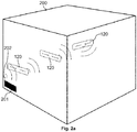
- This is shown in the example in Fig. 2a accomplished by the waveguide structures 120.
- an electromagnetic wave emitted by the module antenna 202 is received by the first antenna 121 of the first waveguide structure 120 and transferred to the second antenna 122 of this first waveguide structure 120.
- the second antenna 122 then in turn emits an electromagnetic wave that is received by the first antenna 121 of the following waveguide structure 120, and so on until finally the electromagnetic wave from the second antenna 122 of the last waveguide structure 120 on the path from the Housing 200 is radiated.
- an electromagnetic wave can thus be guided from the second antenna 122 of the last waveguide structure 120 through the housing 200 to the module antenna 202 of the communication unit 201.
- Figure 2b shows the exemplary use of a waveguide structure 100 on the wall 210 of a housing 200 of a domestic appliance.
- the first antenna 101 of the waveguide structure 100 is arranged on a first (inner) side of the housing wall 210 and can be used to receive an electromagnetic wave emitted by the module antenna 202.
- the first antenna 101 and the module antenna 202 can be resonantly coupled to one another.
- the received electromagnetic wave is then conducted via the conductor track 102 to the other (outer) side of the housing wall 210 and emitted there by the second antenna 103 of the waveguide structure 100.
- an electromagnetic wave can thus be received by the second antenna 103 and forwarded to the module antenna 202 of the communication unit 201.
- These structures 100, 110, 120 consist of coupled structures which are preferably designed to be resonant. With a self-adhesive design, these structures 100, 110, 120 can be flexibly placed in a household appliance.
- the structures 100, 110, 120 can be used to conduct an RF signal through a domestic appliance and to emit it at a suitable point.
- the structures 100, 110, 120 can be placed in the household appliance independently of one another and, if necessary, freely coupled (such as with the structure 120).
- two antenna structures 101, 103 can be coupled via a line 102, the line 102 taking over the waveguide. The first antenna 101 picks up the RF signal and the second antenna 103 emits the RF signal at a suitable point.
- waveguide structures 100, 110, 120 represents a simple and inexpensive alternative to using a coaxial line with an additional antenna in a domestic appliance.
- a touch-sensitive screen which is arranged on the outside of the housing 200 of a household appliance.
- the touch-sensitive screen typically has electrically conductive structures (for example conductor tracks which are arranged on the basis of a backgammon game board).
- the touch-sensitive screen can be used efficiently as an antenna for the emission or reception of electromagnetic waves due to its positioning and possibly due to the available electrically conductive structures.
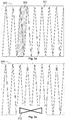
- the touch-sensitive screen 300 comprises triangular-shaped conductor tracks 301, a sub-group 302 of which can be used as an antenna (see FIG Fig. 3a).
- Figure 3b shows an example in which a portion of the screen 300 is used for a dedicated antenna 312 (without using the electrically conductive structures 301 of the screen 300).
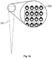
- Figure 3c shows an example in which microstructures 322 for providing an antenna have been integrated into a triangular conductor track 301 of a screen 300.
- a metamaterial can be used for the conductor track 301 of the screen 300, which metamaterial gives the conductor track 301 the function of an antenna.
- a touch overlay 301 (ie the electrically conductive structures) of a touch display 300 can thus be used for the RF emission and for the RF reception.
- additional suitable structures can optionally be applied to the touch overlay (such as a dipole antenna, a metamaterial, etc.).
- the touch overlay 301 is used in addition to the actual function as an antenna.
- the touch overlay 301 can be optimized with regard to an HF function. In particular, as in Figure 3c shown using metamaterials for this purpose.
- a touch-sensitive screen 300 As an antenna, the behavior of a household appliance with regard to RF emission and RF reception can be improved. Due to the position of the touch-sensitive screen 300, the antenna is automatically located on the outside of the housing 200 of a domestic appliance. In addition, a touch-sensitive screen 300 is typically easily accessible and therefore usually has good properties with regard to RF emission / reception. Touch operation on the screen 300 usually only takes place for a short time, so that the HF emission or the HF reception is only insignificantly impaired by touch operation. There is also a cover the antenna structure is unlikely, since the user of a domestic appliance usually wants to see the screen 300.
Landscapes
- Support Of Aerials (AREA)
- Waveguide Aerials (AREA)
Description
- Die Erfindung betrifft ein Hausgerät mit einer Kommunikationseinheit. Das Hausgerät kann eine HF-Übertragungsstrecke aus unabhängigen Wellenleitungs-Strukturen umfassen.
- Vorrichtungen bzw. elektrische Geräte wie Hausgeräte (z.B. Waschmaschinen, Wäschetrockner, Spülmaschinen, Öfen, Kühlschränke, etc.) weisen häufig aus Stabilitätsgründen ein metallisches, und damit für HF (High Frequency)-Strahlen abgeschirmtes, Gehäuse auf. Als Folge daraus, ist es meist schwierig, in solchen Vorrichtungen drahtlose Kommunikationsfähigkeiten (z.B. WLAN, Bluetooth, GPS, UMTS, LTE, etc.) bereitzustellen.
- Solche Geräte sind beispielsweise in der
JP 2014 209053 A CN 103 712 3406 A US 2009/193823 A1 oder derUS 2012/329524 A1 offenbart. - Das vorliegende Dokument befasst sich mit der technischen Aufgabe, in Kosten-effizienter und zuverlässiger Weise drahtlose Kommunikationsfähigkeiten in Vorrichtungen, insbesondere in Hausgeräten, bereitzustellen, die ein abschirmendes Gehäuse aufweisen.
- Die Aufgabe wird durch die unabhängigen Ansprüche gelöst. Vorteilhafte Ausführungsformen werden u.a. in den abhängigen Ansprüchen beschrieben.
- Gemäß einem Aspekt wird eine Vorrichtung beschrieben. Die Vorrichtung kann ein Hausgerät, insbesondere ein Haushaltsgerät wie etwa eine Waschmaschine, ein Wäschetrockner, eine Spülmaschine, ein Ofen, oder ein Kühlschrank, umfassen bzw. einem solchen entsprechen. Die Vorrichtung umfasst ein Gehäuse mit einer Vielzahl von Gehäuse-Wänden. Dabei können ein oder mehrere (ggf. alle) Gehäuse-Wände ein elektrisch leitendes Material (z.B. ein Metall) umfassen. Das Gehäuse kann somit abschirmende Eigenschaften für elektromagnetische Wellen (insbesondere im Bereich von 30MHz bis 300GHz) aufweisen.
- Die Vorrichtung umfasst weiter eine Kommunikationseinheit (in diesem Dokument auch als Kommunikationsmodul bezeichnet) und eine Außen-Antenne, die eingerichtet sind, ein elektromagnetisches Signal zu empfangen bzw. zu senden. Das elektromagnetische Signal kann eine Frequenz in dem o.g. Frequenzbereich von 30MHz bis 300GHz umfassen. Das elektromagnetische Signal kann z.B. ein Bluetooth-Signal oder ein WLAN-Signal umfassen. Insbesondere kann das elektromagnetische Signal einer der Frequenzbandnormen IEEE 802.11 oder IEEE 802.15.1 entsprechen.
- Die Vorrichtung kann einen berührungsempfindlichen Bildschirm umfassen, der es einem Nutzer der Vorrichtung ermöglicht, Steueranweisungen an die Vorrichtung einzugeben. Ein solcher Bildschirm ist typischerweise an einer (für den Nutzer) gut zugänglichen Stelle des Gehäuses (insbesondere an einer Außen-Wand des Gehäuses) angeordnet.
- Die Vorrichtung umfasst weiter eine Kommunikationseinheit und eine Außen-Antenne, die eingerichtet sind, ein elektromagnetisches Signal zu empfangen bzw. zu senden. Dabei kann die Kommunikationseinheit direkt oder indirekt über die Außen-Antenne ein elektromagnetisches Signal empfangen bzw. senden. Insbesondere kann die Außen-Antenne einer Modul-Antenne der Kommunikationseinheit entsprechen, die direkt mit der Kommunikationseinheit verbunden ist. Alternativ kann die Außen-Antenne einer zweiten Antenne einer in diesem Dokument beschriebenen Wellenleitungs-Struktur entsprechen.
- Die Außen-Antenne kann derart in oder an dem berührungsempfindlichen Bildschirm angeordnet sein, dass mittels der Außen-Antenne ein elektromagnetisches Signal an einen Empfänger außerhalb des Gehäuses gesendet bzw. von einem Sender außerhalb des Gehäuses empfangen werden kann. So kann erreicht werden, dass die Außen-Antenne das elektromagnetische Signal in zuverlässiger (d.h. möglichst ungedämpfter) Weise an einen externen Kommunikationspartner senden bzw. von diesem empfangen kann. Durch die Anordnung der Außen-Antenne in oder an dem berührungsempfindlichen Bildschirm werden somit in Kosten-effizienter und zuverlässiger Weise drahtlose Kommunikationsfähigkeiten in einer Vorrichtung bereitgestellt, die ein abschirmendes Gehäuse aufweist.
- Wie bereits oben dargelegt, kann die Kommunikationseinheit eine Modul-Antenne aufweisen. Die Kommunikationseinheit und die Modul-Antenne können dabei in dem Gehäuse (d.h. im Innenraum des Gehäuses) angeordnet sein, so dass durch die Anordnung der Kommunikationseinheit und der Modul-Antenne eine Kommunikation zwischen der Kommunikationseinheit und einem Kommunikationspartner (d.h. einem Sender bzw. Empfänger) außerhalb des Gehäuses der Vorrichtung erschwert wird (insbesondere aufgrund einer abschirmenden Wirkung des Gehäuses).
- Die Vorrichtung kann weiter zumindest eine Wellenleitungs-Struktur mit einer ersten Antenne und einer zweiten Antenne umfassen. Die Wellenleitungs-Struktur ist zumindest teilweise im Gehäuse der Vorrichtung angeordnet. Die Wellenleitungs-Struktur ist eingerichtet, ein von der Modul-Antenne ausgesendetes elektromagnetisches Signal mittels der ersten Antenne zu empfangen und mittels der zweiten Antenne (wieder) auszusenden. Dabei kann die zweite Antenne der Außen-Antenne entsprechen. In umgekehrter Richtung ist die Wellenleitungs-Struktur eingerichtet, mittels der zweiten Antenne ein elektromagnetisches Signal zu empfangen und mittels der ersten Antenne an die Modul-Antenne zu senden. Zu diesem Zweck ist typischerweise zumindest die erste Antenne im Gehäuse der Vorrichtung angeordnet. Die Wellenleitungs-Struktur ist somit eingerichtet, ein elektromagnetisches Signal innerhalb des Gehäuses der Vorrichtung weiterzuleiten. Dabei handelt es sich bei der Wellenleitungs-Struktur bevorzugt um eine passive Struktur (ohne eine elektrische Energieversorgung), die somit in besonders Kosten-günstiger Weise bereitgestellt werden.
- Die zweite Antenne (insbesondere die Außen-Antenne) kann derart angeordnet sein, dass mittels der zweiten Antenne ein elektromagnetisches Signal an einen Empfänger außerhalb des Gehäuses gesendet bzw. von einem Sender außerhalb des Gehäuses empfangen werden kann. Die zweite Antenne kann zu diesem Zweck ggf. außerhalb des Gehäuses der Vorrichtung angeordnet sein. Alternativ kann die zweite Antenne zu diesem Zweck an einer Stelle des Gehäuses angeordnet sein, an dem das Gehäuse (im Vergleich zu einer anderen Stelle des Gehäuses) einen relativ hohen Transmissionsgrad für das elektromagnetische Signal aufweist (z.B. einen Transmissionsgrad von 50%, 70%, 90% oder mehr).
- Die Verwendung einer derart angeordneten Wellenleitungs-Struktur ermöglicht es, in Kosten-effizienter und zuverlässiger Weise Kommunikationsfähigkeiten in einer Vorrichtung, insbesondere in einem Hausgerät, bereitzustellen. Es können somit in effizienter Weise drahtlos vernetzte Vorrichtungen bereitgestellt werden.
- Die Wellenleitungs-Struktur kann eine elektrisch leitende Leiterbahn umfassen, die eingerichtet ist, das elektromagnetische Signal zwischen der ersten Antenne und der zweiten Antenne zu übertragen. So kann z.B. das elektromagnetische Signal über die Leiterbahn von der ersten Antenne innerhalb des Gehäuses zu der zweiten Antenne außerhalb des Gehäuses geleitet werden (oder umgekehrt). Somit kann die Kommunikationseinheit in effizienter Weise mit einem externen Kommunikationspartner außerhalb des Gehäuses (z.B. mit einem WLAN Access Point) kommunizieren.
- Wie bereits dargelegt, kann das Gehäuse eine (erste) Wand mit einem elektrisch leitenden Material (z.B. Metall) umfassen. Die Wellenleitungs-Struktur kann eine dielektrische Schicht aufweisen, auf der die Leiterbahn angeordnet ist. Die dielektrische Schicht kann dabei als Trägerschicht für die Leiterbahn dienen. Die Wellenleitungs-Struktur kann derart auf der ersten Wand angeordnet sein, dass die dielektrische Schicht die Leiterbahn von der ersten Wand isoliert. Beispielsweise kann die Wellenleitungs-Struktur eine Klebeschicht aufweisen, mit der die dielektrische Schicht auf die erste Wand geklebt werden kann. Somit kann eine elektrisch leitende (erste) Wand des Gehäuses in effizienter Weise als Masse für einen Streifenleiter (in Englisch "microstrip") verwendet werden. Der so entstehende Streifenleiter ist eingerichtet, das elektromagnetische Signal mit relativ niedrigen Verlusten zwischen der ersten Antenne und der zweiten Antenne zu übertragen.
- Alternativ kann die Wellenleitungs-Struktur derart ausgelegt sein, dass das elektromagnetische Signal zwischen der ersten Antenne und der zweiten Antenne durch elektromagnetische Kopplung, insbesondere durch resonante Kopplung, der ersten Antenne und der zweiten Antenne übertragen wird. Zu diesem Zweck können die erste Antenne und die zweite Antenne derart aufgebaut sein, dass die erste Antenne und die zweite Antenne eine gemeinsame Resonanzfrequenz aufweisen. Insbesondere können die erste Antenne und die zweite Antenne gleich aufgebaut sein. Durch die Verwendung von resonant gekoppelten Antennen kann eine relativ verlustfreie Übertragung des elektromagnetischen Signals zwischen der ersten und der zweiten Antenne bewirkt werden. In analoger Weise können auch die erste Antenne der Wellenleitungs-Struktur und die Modul-Antenne über eine resonante, elektromagnetische Kopplung gekoppelt sein, um eine möglichst verlustfreie Übertragung des elektromagnetischen Signals zu ermöglichen.
- Die Vorrichtung kann eine Vielzahl von Wellenleitungs-Strukturen umfassen. Dabei sind die Wellenleitungs-Strukturen derart angeordnet, dass jeweils eine zweite Antenne einer ersten Wellenleitungs-Struktur mit einer ersten Antenne einer benachbarten zweiten Wellenleitungs-Struktur (resonant) gekoppelt ist. So kann die Vielzahl von Wellenleitungs-Strukturen einen Pfad für das elektromagnetische Signal von der Modul-Antenne aus dem Gehäuse heraus, bzw. von außerhalb des Gehäuses zu der Modul-Antenne bilden. Insbesondere kann die erste Antenne einer ersten Wellenleitungs-Struktur auf dem Pfad mit der Modul-Antenne (resonant) gekoppelt sein. Desweiteren kann die zweite Antenne einer letzten Wellenleitungs-Struktur auf dem Pfad eine Funkverbindung mit einem Kommunikationspartner außerhalb des Gehäuses ermöglichen. Durch Verwendung von aneinander gereihten Wellenleitungs-Strukturen kann in Kosten-effizienter und zuverlässiger Weise eine Kommunikationsverbindung zwischen einem externen Kommunikationspartner (z.B. mit einem WLAN Acces Point) und der Kommunikationseinheit aufgebaut werden.
- Die Wellenleitungs-Struktur kann eine Trägerschicht aufweisen (welche z.B. die dielektrische Schicht umfasst). Die erste Antenne und die zweite Antenne können auf die Trägerschicht gedruckt sein. Auch eine Leiterbahn der Wellenleitungs-Struktur kann auf die Trägerschicht gedruckt sein. Es kann somit eine Kostengünstige gedruckte Wellenleitungs-Struktur in der Vorrichtung verwendet werden.
- Die Wellenleitungs-Struktur kann eine Klebeschicht aufweisen, mit der die (gedruckte) Wellenleitungs-Struktur auf eine Wand des Gehäuses geklebt werden kann. So wird ein effizienter Verbau der Wellenleitungs-Struktur im Gehäuse der Vorrichtung ermöglicht.
- Der berührungsempfindliche Bildschirm umfasst gemäß der Erfindung typischerweise elektrisch leitende Strukturen, die eingerichtet sind, eine Berührung des Bildschirms zu detektieren. Beispielsweise können auf dem berührungsempfindlichen Bildschirm (dreieckförmige) Leiterbahnen angeordnet sein, um die Position einer Berührung des Bildschirms zu detektieren. Die zweite Antenne kann zumindest einen Teil der elektrisch leitenden Strukturen umfassen. Mit anderen Worten, die zweite Antenne kann zumindest teilweise in die elektrisch leitenden Strukturen des Bildschirms integriert sein. Dies ermöglicht eine besonders Kosten- und Bauraum-effektive Bereitstellung von drahtlosen Kommunikationsfähigkeiten in einer Vorrichtung.
- Die elektrisch leitenden Strukturen umfassen erfindungsgemäß zumindest teilweise ein Metamaterial, das den elektrisch leitenden Strukturen die Eigenschaft einer Antenne verleiht. Insbesondere kann das Metamaterial eine Vielzahl von (gleichen) mikroskopischen Strukturen aufweisen (z.B. mit einer jeweiligen Größe von 2mm, 1mm oder weniger), die jeweils eine Antennen-Funktion aufweisen. Durch die Vielzahl von mikroskopischen Strukturen kann dann eine zweite Antenne bereitgestellt werden, die elektromagnetische Signale mit einer bestimmten Reichweite (z.B. 50m, 100m oder mehr) aussenden bzw. empfangen kann. Beispielsweise kann das Metamaterial eine Vielzahl von (mikroskopischen) elektromagnetischen Schwingkreisen umfassen. So kann in effektiver Weise die Funktion eines berührungsempfindlichen Bildschirms mit einer Antennen-Funktion kombiniert werden.
- Alternativ oder ergänzend kann die zweite Antenne in einem berührungsunempfindlichen Teil des Bildschirms angeordnet sein. So kann gewährleistet werden, dass die zweite Antenne möglichst dämpfungsfrei elektromagnetische Signale mit einem externen Kommunikationspartner austauschen kann.
- Gemäß einem weiteren Aspekt wird eine Wellenleitungs-Struktur zur Weiterleitung eines elektromagnetischen Signals beschrieben. Die Wellenleitungs-Struktur kann ein oder mehrere der in diesem Dokument beschriebenen Merkmale aufweisen. Insbesondere kann die Wellenleitungs-Struktur eine (typischerweise dielektrische) Trägerschicht mit einer ersten Seite und einer zweiten Seite aufweisen. Die Trägerschicht kann auf der ersten Seite selbstklebend sein, so dass die Wellenleitungs-Struktur mit der ersten Seite auf einer Fläche (z.B. auf einer Gehäuse-Wand) befestigt werden kann.
- Desweiteren umfasst die Wellenleitungs-Struktur eine erste Antenne und eine zweite Antenne, die auf der zweiten Seite der Trägerschicht angeordnet sind. Insbesondere können die erste Antenne und die zweite Antenne auf die zweite Seite der Trägerschicht gedruckt sein. Die Antennen sind derart ausgestaltet, dass die Wellenleitungs-Struktur mittels der ersten Antenne ein elektromagnetisches Signal empfangen und mittels der zweiten Antenne das elektromagnetische Signal auszusenden kann (und/oder umgekehrt). Somit kann die Wellenleitungs-Struktur in effizienter Weise zur Weiterleitung eines elektromagnetischen Signals (z.B. zur Weiterleitung durch ein abschirmendes Gehäuse) verwendet werden. Insbesondere kann durch eine Aneinanderreihung von Wellenleitungs-Strukturen ein Übertragungspfad für ein elektromagnetisches Signal aufgebaut werden.
- Die Wellenleitungs-Struktur (insbesondere die Trägerschicht) weist typischerweise eine Länge und/oder eine Breite von 1-10cm auf. Desweiteren weist die Wellenleitungs-Struktur typischerweise eine Dicke (senkrecht zur Trägerschicht) im Bereich von 1mm auf. Eine selbstklebende Wellenleitungs-Struktur kann so als eine Art "Pflaster" oder "Sticker" ausgestaltet sein, der an die Wände eines abschirmenden Gehäuses geklebt werden kann, um einen Übertragungspfad für ein elektromagnetisches Signal bereitzustellen.
- Gemäß einem weiteren Aspekt wird die Verwendung von ein oder mehreren, der in diesem Dokument beschriebenen, Wellenleitungs-Strukturen zur Weiterleitung eines elektromagnetischen Signals.
- Gemäß einem weiteren Aspekt wird ein Hausgerät, insbesondere ein Haushaltsgerät wie etwa eine Waschmaschine, ein Wäschetrockner, eine Spülmaschine, ein Ofen, oder ein Kühlschrank, beschrieben. Das Hausgerät umfasst ein Gehäuse mit einer Vielzahl von Gehäuse-Wänden. Dabei können ein oder mehrere (ggf. alle) Gehäuse-Wände ein elektrisch leitendes Material (z.B. ein Metall) umfassen. Das Gehäuse kann somit abschirmende Eigenschaften für elektromagnetische Wellen (insbesondere im Bereich von 30MHz bis 300GHz) aufweisen. Das Hausgerät kann eine beliebige Kombination der in diesem Dokument beschriebenen Merkmale aufweisen.
- Insbesondere umfasst das Hausgerät einen berührungsempfindlichen Bildschirm, der an einer Außen-Wand des Gehäuses angeordnet ist. Der berührungsempfindliche Bildschirm ermöglicht es einem Nutzer des Hausgeräts, Steueranweisungen an das Hausgerät einzugeben. Typischerweise umfasst der berührungsempfindliche Bildschirm elektrisch leitende Strukturen, die eingerichtet sind, eine Berührung des Bildschirms zu detektieren.
- Desweiteren umfasst das Hausgerät eine Kommunikationseinheit und eine Antenne (z.B. eine Modul-Antenne), die eingerichtet sind, ein elektromagnetisches Signal zu empfangen bzw. zu senden. Das elektromagnetische Signal kann eine Frequenz in dem o.g. Frequenzbereich von 30MHz bis 300GHz umfassen. Das elektromagnetische Signal kann z.B. ein Bluetooth-Signal oder ein WLAN-Signal umfassen. Insbesondere kann das elektromagnetische Signal einer der Frequenzbandnormen IEEE 802.11 oder IEEE 802.15.1 entsprechen.
- Die Kommunikationseinheit ist in dem Gehäuse angeordnet. Andererseits ist die Antenne in oder an dem berührungsempfindlichen Bildschirm angeordnet. Insbesondere kann die Antenne zumindest einen Teil der elektrisch leitenden Strukturen des berührungsempfindlichen Bildschirms umfassen. So kann eine Bauraum-effiziente und zuverlässige (d.h. möglichst dämpfungsfreie) drahtlose Kommunikationsfähigkeit in einem Hausgerät bereitgestellt werden.
- Es ist zu beachten, dass die in diesem Dokument beschriebenen Vorrichtungen und Systeme sowohl alleine, als auch in Kombination mit anderen in diesem Dokument beschriebenen Vorrichtungen und Systemen verwendet werden können. Desweiteren können jegliche Aspekte der in diesem Dokument beschriebenen Vorrichtungen und Systeme in vielfältiger Weise miteinander kombiniert werden. Insbesondere können die Merkmale der Ansprüche in vielfältiger Weise miteinander kombiniert werden.
- Im Weiteren wird die Erfindung anhand von Ausführungsbeispielen näher beschrieben. Dabei zeigen
- Figuren 1a, 1b, 1c
- beispielhafte Wellenleitungs-Strukturen zur Leitung von elektromagnetischen Wellen;
- Figuren 2a, 2b
- beispielhafte Anordnungen von Wellenleitungs-Strukturen in einem Hausgerät; und
- Figuren 3a, 3b, 3c
- beispielhafte Antennen-Strukturen an oder in einem berührungsempfindlichen Bildschirm eines Hausgeräts.
- Wie eingangs dargelegt, befasst sich das vorliegende Dokument mit der effizienten Bereitstellung von drahtlosen Kommunikationsfähigkeiten in einer Vorrichtung bzw. in einem Gerät mit einem zumindest teilweise abschirmenden Gehäuse. Die Vorrichtung bzw. das Gerät entsprechen bevorzugt einem Hausgerät. Alternativ sind aber auch andere Vorrichtungen mit zumindest teilweise abschirmenden Gehäusen denkbar, z.B. Kraftfahrzeuge mit einer abschirmenden Karosserie. Für die Kommunikation über eine drahtlose Kommunikationsverbindung kann das Hausgerät eines Kommunikationseinheit 201 (siehe
Figuren 2a und2b ) mit einer Antenne 202 aufweisen. Die Kommunikationseinheit 201 kann z.B. eingerichtet sein, eine WLAN, Bluetooth, GPS, UMTS, LTE, etc. Kommunikationsverbindung mit einem Kommunikationspartner aufzubauen. - Für den Aufbau einer zuverlässigen Kommunikationsverbindung müssten die Kommunikationseinheit 201 mit der Antenne 202 an einem Ort innerhalb des Gehäuses 200 eines Hausgeräts angeordnet sein, an dem eine möglichst verlustfreie Abstrahlung und ein möglichst verlustfreier Empfang von elektromagnetischen Strahlen in einem Frequenzbereich zwischen 3MHz und 300GHz, insbesondere zwischen 30Mhz und 300GHz, möglich ist. Dies ist jedoch insbesondere bei Verwendung eines metallischen Gehäuses 200 typischerweise nicht möglich.
- Eine Möglichkeit ist es, die Kommunikationseinheit 201 an einem beliebigen Ort in dem Gehäuse 200 eines Hausgeräts zu verbauen, und eine zusätzliche Antenne an einem günstigen Abstrahl/Empfangs-Ort über eine koaxiale Leitung mit der Kommunikationseinheit 201 zu verbinden. Eine derartige Verkabelung durch das Gehäuse 200 eines Hausgeräts ist jedoch aufwändig und Kosen-intensiv.
- In effektiver Weise können stattdessen gedruckte Wellenleitungs-Strukturen 100, 110, 120 (siehe
Figuren 1a, 1b, 1c ) verwendet werden, um die über eine Antenne 202 (in diesem Dokument auch als Modul-Antenne bezeichnet) der Kommunikationseinheit 201 abgestrahlten elektromagnetischen Wellen aus dem Gehäuse 200 des Hausgeräts zu leiten bzw. in umgekehrter Richtung elektromagnetische Wellen von außerhalb des Gehäuses 200 zu der Antenne 202 der Kommunikationseinheit 201 zu leiten. - Die Wellenleitungs-Strukturen 100, 110 umfassen eine erste Antenne 101, eine Leiterbahn 102 und eine zweite Antenne 103. Eine elektromagnetische Welle wird über die erste Antenne 101 empfangen, über die Leiterbahn 102 an die zweite Antenne 103 geleitet und von der zweiten Antenne 103 ausgestrahlt (oder umgekehrt). Dabei ist die Leiterbahn 102 typischerweise auf einer dielektrischen Trägerschicht 105 der Wellenleitungs-Struktur 100, 110 angeordnet.
- Die Wellenleitungs-Struktur 120 umfasst eine erste Antenne 121 und eine zweite Antenne 122, die miteinander (resonant) gekoppelt sind, und somit die Übertragung einer elektromagnetischen Welle von der ersten Antenne 121 auf die zweite Antenne 122 (oder umgekehrt) ermöglichen. Die Antennen 121, 122 sind dabei auf einer Trägerschicht 105 angeordnet.
- Anhand der Wellenleitungs-Strukturen 100, 110, 120 kann in flexibler und effizienter Weise ein Pfad durch das Gehäuse 200 eines Hausgeräts aufgebaut werden, um eine elektromagnetische Welle von der Modul-Antenne 202 einer Kommunikationseinheit 201 aus dem Gehäuse 200 heraus zu leiten, bzw. in umgekehrter Richtung eine elektromagnetische Welle von einem Punkt außerhalb des Gehäuses 200 zu der Modul-Antenne 202 der Kommunikationseinheit 201 zu leiten. Dies wird in dem Beispiel in
Fig. 2a durch die Wellenleitungs-Strukturen 120 bewerkstelligt. Dabei wird eine von der Modul-Antenne 202 abgestrahlte elektromagnetische Welle von der ersten Antenne 121 der ersten Wellenleitungs-Struktur 120 empfangen, und an die zweite Antenne 122 dieser ersten Wellenleitungs-Struktur 120 übergeben. Die zweite Antenne 122 strahlt dann wiederum eine elektromagnetische Welle ab, die von der ersten Antenne 121 der folgenden Wellenleitungs-Struktur 120 empfangen wird, usw. bis schließlich die elektromagnetische Welle von der zweiten Antenne 122 der letzten Wellenleitungs-Struktur 120 auf dem Pfad aus dem Gehäuse 200 abgestrahlt wird. In umgekehrter Richtung kann so eine elektromagnetische Welle von der zweiten Antenne 122 der letzten Wellenleitungs-Struktur 120 durch das Gehäuse 200 zu der Modul-Antenne 202 der Kommunikationseinheit 201 geführt werden. -
Fig. 2b zeigt die beispielhafte Verwendung einer Wellenleitungs-Struktur 100 an der Wand 210 eines Gehäuses 200 eines Hausgeräts. Die erste Antenne 101 der Wellenleitungs-Struktur 100 ist auf einer ersten (inneren) Seite der Gehäuse-Wand 210 angeordnet und kann dazu verwendet werden, eine von der Modul-Antenne 202 abgestrahlte elektromagnetische Welle zu empfangen. Zu diesem Zweck können die erste Antenne 101 und die Modul-Antenne 202 resonant miteinander gekoppelt sein. Die empfangene elektromagnetische Welle wird dann über die Leiterbahn 102 auf die andere (äußere) Seite der Gehäuse-Wand 210 geleitet und dort von der zweiten Antenne 103 der Wellenleitungs-Struktur 100 abgestrahlt. In umgekehrter Richtung kann so eine elektromagnetische Welle von der zweiten Antenne 103 empfangen und an die Modul-Antenne 202 der Kommunikationseinheit 201 weitergeleitet werden. - Es wird somit die Verwendung von relativ einfachen gedruckten Strukturen 100, 110, 120 zur HF (High Frequency)-Wellenleitung in einem Hausgerät beschrieben. Diese Strukturen 100, 110, 120 bestehen aus gekoppelten Strukturen die bevorzugt resonant ausgebildet sind. Selbstklebend ausgeführt lassen sich diese Strukturen 100, 110, 120 flexible in einem Hausgerät platzieren. Die Strukturen 100, 110, 120 können dazu verwendet werden, ein HF-Signal durch ein Hausgerät zu leiten und an geeigneter Stelle abzustrahlen. Die Strukturen 100, 110, 120 können dabei unabhängig voneinander im Hausgerät platziert und ggf. frei gekoppelt sein (wie z.B. bei der Struktur 120). Alternativ können zwei Antennenstrukturen 101, 103 über eine Leitung 102 gekoppelt sein, wobei die Leitung 102 die Wellenleitung übernimmt. Dabei nimmt die erste Antenne 101 das HF-Signal auf und die zweite Antenne 103 strahlt das HF-Signal an geeigneter Stelle ab.
- Die Verwendung von Wellenleitungs-Strukturen 100, 110, 120 stellt eine einfache und Kosten-günstig realisierbare Alternative zu der Verwendung einer koaxialen Leitung mit zusätzlicher Antenne in einem Hausgerät dar.
- Auch bei Verwendung von Wellenleitungs-Strukturen 100, 110, 120 kann es schwierig sein, eine geeignete Stelle am Gehäuse 200 eines Hausgeräts für die Abstrahlung / für den Empfang von elektromagnetischen Wellen zu reservieren. Andererseits weisen Hausgeräte häufig einen berührungsempfindlichen Bildschirm auf, der an der Außenseite des Gehäuses 200 eines Hausgeräts angeordnet ist. Der berührungsempfindliche Bildschirm weist typischerweise elektrisch leitende Strukturen (z.B. Leiterbahnen, die in Anlehnung an ein Backgammon-Spielbrett angeordnet sind) auf.
- Der berührungsempfindliche Bildschirm kann aufgrund seiner Positionierung und ggf. aufgrund der verfügbaren elektrisch leitenden Strukturen in effizienter Weise als Antenne für die Abstrahlung bzw. für den Empfang von elektromagnetischen Wellen verwendet werden. Dies ist beispielhaft in den
Figuren 3a, 3b ,3c gezeigt. Der berührungsempfindliche Bildschirm 300 umfasst Dreieck-förmige Leiterbahnen 301, von denen eine Untergruppe 302 als Antenne verwendet werden kann (sieheFig. 3a). Fig. 3b zeigt ein Beispiel, bei dem ein Teilbereich des Bildschirms 300 für eine dedizierte Antenne 312 verwendet wird (ohne Verwendung der elektrisch leitenden Strukturen 301 des Bildschirms 300).Fig. 3c zeigt ein Beispiel, bei dem in eine Dreieck-förmige Leiterbahn 301 eines Bildschirms 300 Mikrostrukturen 322 zur Bereitstellung einer Antenne integriert wurden. Mit anderen Worten kann für die Leiterbahn 301 des Bildschirms 300 ein Metamaterial verwendet werden, das der Leiterbahn 301 die Funktion einer Antenne verleiht. - Es kann somit ein Touch-Overlay 301 (d.h. es können die elektrisch leitfähigen Strukturen) eines Touch-Displays 300 für die HF-Abstrahlung und für den HF-Empfang verwendet werden. Hierzu können ggf. zusätzliche geeignete Strukturen auf das Touch-Overlay aufgebracht werden (wie z.B. eine Dipolantenne, ein Metamaterial, etc.). Alternativ ist es möglich, ein HF-Signal geeignet in vorhandene Strukturen 301 des Touch-Displays 300 einzukoppeln. Hierbei wird das Touch-Overlay 301 zusätzlich zu der eigentlichen Funktion als Antenne verwendet. Der Touch-Overlay 301 kann dabei in Hinblick auf eine HF-Funktion optimiert werden. Insbesondere können, wie z.B. in
Fig. 3c gezeigt, zu diesem Zweck Metamaterialien verwendet werden. - Durch die Verwendung eines berührungsempfindlichen Bildschirms 300 als Antenne kann das Verhalten eines Hausgerätes in Bezug auf HF-Abstrahlung und HF-Empfang verbessert werden. Aufgrund der Position des berührungsempfindlichen Bildschirms 300 liegt dabei die Antenne automatisch an der Außenseite des Gehäuses 200 eines Hausgeräts. Außerdem ist ein berührungsempfindlicher Bildschirm 300 typischerweise einfach zugänglich, und weist daher meist gute Eigenschaften in Bezug auf HF-Abstrahlung / Empfang auf. Eine Touchbedienung auf dem Bildschirm 300 erfolgt üblicherweise nur für kurze Zeit, so dass die HF-Abstrahlung bzw. der HF-Empfang durch eine Touchbedienung nur unwesentlich beeinträchtigt wird. Außerdem ist eine Abdeckung der Antennenstruktur unwahrscheinlich, da der Nutzer eines Hausgeräts den Bildschirm 300 üblicherweise sehen möchte.
- Die vorliegende Erfindung ist nicht auf die gezeigten Ausführungsbeispiele beschränkt. Insbesondere ist zu beachten, dass die Beschreibung und die Figuren nur das Prinzip der vorgeschlagenen Vorrichtungen und Systeme veranschaulichen sollen.
Claims (7)
- Hausgerät, das umfasst,- ein Gehäuse (200);- einen berührungsempfindlichen Bildschirm (300), der an einer Außen-Wand (210) des Gehäuses (200) angeordnet ist; und- eine Kommunikationseinheit (201) und eine Außen-Antenne (103, 122), die eingerichtet sind, ein elektromagnetisches Signal zu empfangen bzw. zu senden; wobei die Kommunikationseinheit (201) in dem Gehäuse (200) angeordnet ist; und wobei die Außen-Antenne (103, 122) derart in oder an dem berührungsempfindlichen Bildschirm (300) angeordnet ist, dass mittels der Außen-Antenne (103, 122) ein elektromagnetisches Signal an einen Empfänger außerhalb des Gehäuses (200) gesendet bzw. von einem Sender außerhalb des Gehäuses (200) empfangen werden kann,
dadurch gekennzeichnet, dass- der berührungsempfindliche Bildschirm (300) elektrisch leitende Strukturen (301) umfasst, die eingerichtet sind, eine Berührung des Bildschirms (300) zu detektieren; und- die Außen-Antenne (202, 103, 122) zumindest einen Teil der elektrisch leitenden Strukturen (301) umfasst, und- wobei die elektrisch leitenden Strukturen (301) zumindest teilweise ein Metamaterial umfassen, das den elektrisch leitenden Strukturen (301) die Eigenschaft einer Antenne verleiht; und- das Metamaterial insbesondere eine Vielzahl von elektromagnetischen Schwingkreisen (322) umfasst. - Hausgerät gemäß Anspruch 1, wobei- die Kommunikationseinheit (201) eine Modul-Antenne (202) umfasst;- das Hausgerät zumindest eine Wellenleitungs-Struktur (100, 110, 120) mit einer ersten Antenne (101, 121) und einer zweiten Antenne (103, 122) umfasst,- die Wellenleitungs-Struktur (100, 110, 120) eingerichtet ist,- ein von der Modul-Antenne (202) ausgesendetes elektromagnetisches Signal mittels der ersten Antenne (101, 121) zu empfangen und mittels der zweiten Antenne (103, 122) auszusenden; und/oder- mittels der zweiten Antenne (103, 122) ein elektromagnetisches Signal zu empfangen und mittels der ersten Antenne (101, 121) an die Modul-Antenne (202) zu senden;- die zweite Antenne (103, 122) die Außen-Antenne (103, 122) ist.
- Hausgerät gemäß Anspruch 2, wobei die Wellenleitungs-Struktur (100, 110, 120) eine elektrisch leitende Leiterbahn (102) umfasst, die eingerichtet ist, das elektromagnetische Signal zwischen der ersten Antenne (101) und der zweiten Antenne (103) zu übertragen.
- Hausgerät gemäß Anspruch 3, wobei- das Gehäuse (200) eine erste Wand (210) mit einem elektrisch leitenden Material umfasst;- die Wellenleitungs-Struktur (100, 110, 120) eine dielektrische Schicht (105) aufweist, auf der die Leiterbahn (102) angeordnet ist; und- die Wellenleitungs-Struktur (100, 110, 120) auf der ersten Wand (210) angeordnet ist, so dass die dielektrische Schicht (105) die Leiterbahn (102) von der ersten Wand (210) isoliert.
- Hausgerät gemäß einem der Ansprüche 2 bis 4, wobei die Wellenleitungs-Struktur (100, 110, 120) derart ausgelegt ist, dass das elektromagnetische Signal zwischen der ersten Antenne (121) und der zweiten Antenne (122) durch elektromagnetische Kopplung, insbesondere durch resonante Kopplung, der ersten Antenne (121) und der zweiten Antenne (122) übertragen wird.
- Hausgerät gemäß einem der Ansprüche 2 bis 5, wobei das Hausgerät eine Vielzahl von Wellenleitungs-Strukturen (100, 110, 120) umfasst, wobei die Vielzahl von Wellenleitungs-Strukturen (100, 110, 120) einen Pfad für das elektromagnetische Signal von der Modul-Antenne (202) aus dem Gehäuse (200) heraus, bzw. von außerhalb des Gehäuses (200) zu der Modul-Antenne (202) bildet.
- Hausgerät gemäß einem der Ansprüche 2 bis 6, wobei- die Wellenleitungs-Struktur (100, 110, 120) eine Trägerschicht (105) aufweist; und- die erste Antenne (101, 121) und die zweite Antenne (103, 122) auf die Trägerschicht (105) gedruckt sind; und/oder die Wellenleitungs-Struktur (100, 110, 120) eine Klebeschicht aufweist, mit der die Wellenleitungs-Struktur (100, 110, 120) auf eine Wand (210) des Gehäuses (200) geklebt werden kann.
Applications Claiming Priority (2)
| Application Number | Priority Date | Filing Date | Title |
|---|---|---|---|
| DE102015219492.2A DE102015219492A1 (de) | 2015-10-08 | 2015-10-08 | HF-Übertragungsstrecke aus unabhängigen Wellenleitungs-Strukturen |
| PCT/EP2016/073745 WO2017060274A1 (de) | 2015-10-08 | 2016-10-05 | Hf-übertragungsstrecke in einem hausgerät |
Publications (2)
| Publication Number | Publication Date |
|---|---|
| EP3360200A1 EP3360200A1 (de) | 2018-08-15 |
| EP3360200B1 true EP3360200B1 (de) | 2020-12-09 |
Family
ID=57136839
Family Applications (1)
| Application Number | Title | Priority Date | Filing Date |
|---|---|---|---|
| EP16781706.3A Active EP3360200B1 (de) | 2015-10-08 | 2016-10-05 | Hf-übertragungsstrecke in einem hausgerät |
Country Status (4)
| Country | Link |
|---|---|
| EP (1) | EP3360200B1 (de) |
| CN (1) | CN108140938B (de) |
| DE (1) | DE102015219492A1 (de) |
| WO (1) | WO2017060274A1 (de) |
Families Citing this family (1)
| Publication number | Priority date | Publication date | Assignee | Title |
|---|---|---|---|---|
| DE102018111711A1 (de) * | 2018-05-16 | 2019-11-21 | Tridonic Gmbh & Co Kg | Leuchte mit Transponder für Parametrierung und Adressierung |
Family Cites Families (9)
| Publication number | Priority date | Publication date | Assignee | Title |
|---|---|---|---|---|
| US7429953B2 (en) * | 2006-03-03 | 2008-09-30 | Motorola, Inc. | Passive repeater for radio frequency communications |
| CN101479546A (zh) * | 2006-07-04 | 2009-07-08 | Lg电子株式会社 | 具有无线通信功能的制冷器 |
| US20090193823A1 (en) * | 2006-07-04 | 2009-08-06 | Ik-Kyu Lee | Refrigerator with wireless communication function |
| US8115688B2 (en) * | 2008-10-24 | 2012-02-14 | Intelleflex Corporation | RF conduit and systems implementing same |
| US20120329524A1 (en) * | 2011-06-22 | 2012-12-27 | Kent Joel C | Touch sensor and antenna integration along an electronic device housing |
| CN103712406B (zh) * | 2012-09-28 | 2016-09-07 | 海信(山东)冰箱有限公司 | 一种带有双天线的冰箱及其控制方法 |
| US9375125B2 (en) * | 2012-12-20 | 2016-06-28 | Whirlpool Corporation | Household appliance having antennas |
| JP6402353B2 (ja) * | 2013-03-29 | 2018-10-10 | パナソニックIpマネジメント株式会社 | 冷蔵庫及び冷蔵庫システム |
| DE102014204495B4 (de) * | 2014-03-12 | 2016-02-25 | Schaeffler Technologies AG & Co. KG | Passiver Repeater zur Weiterleitung von Funksignalen, Funksystem, Fahrzeug und Lager mit einem passiven Repeater und Verwendung eines passiven Repeaters |
-
2015
- 2015-10-08 DE DE102015219492.2A patent/DE102015219492A1/de not_active Withdrawn
-
2016
- 2016-10-05 EP EP16781706.3A patent/EP3360200B1/de active Active
- 2016-10-05 CN CN201680058171.7A patent/CN108140938B/zh active Active
- 2016-10-05 WO PCT/EP2016/073745 patent/WO2017060274A1/de not_active Ceased
Non-Patent Citations (1)
| Title |
|---|
| None * |
Also Published As
| Publication number | Publication date |
|---|---|
| EP3360200A1 (de) | 2018-08-15 |
| WO2017060274A1 (de) | 2017-04-13 |
| DE102015219492A1 (de) | 2017-04-13 |
| CN108140938A (zh) | 2018-06-08 |
| CN108140938B (zh) | 2021-02-12 |
Similar Documents
| Publication | Publication Date | Title |
|---|---|---|
| EP3100070B1 (de) | Radarsystem zur umfelderfassung für ein fahrzeug | |
| JP5616338B2 (ja) | 平行な伝導表面間のギャップにおける導波管と伝送ライン | |
| DE60102099T2 (de) | Dielektrisches Resonatorfilter | |
| EP3641053B1 (de) | Antenne für nahbereichsanwendungen sowie verwendung einer derartigen antenne | |
| US7821361B2 (en) | Second-order band-pass filter and wireless apparatus using the same | |
| JP2016105583A (ja) | アンテナ装置、無線通信装置、及びレーダ装置 | |
| WO2012119818A1 (de) | Leiterplattenanordnung für millimeterwellen-scanner | |
| WO1998038694A1 (de) | Resonanzantenne | |
| CN107181058B (zh) | 一种新型双波束定向辐射mimo贴片天线及移动终端 | |
| CN108470978A (zh) | 基于金属框的5g mimo天线系统 | |
| EP3134748B1 (de) | Radarsystem zur umfelderfassung für ein fahrzeug sowie platine für ein solches radarsystem | |
| JP2017216589A (ja) | フィルタ | |
| EP2489095B1 (de) | Antennenkoppler | |
| DE102014218339A1 (de) | Einrichtung zur Übertragung von Millimeterwellensignalen | |
| DE102019201262A1 (de) | Teilnehmer eines Kommunikationssystems mit einer magnetischen Antenne | |
| US20090058556A1 (en) | Antenna end filter arrangement | |
| US10505251B2 (en) | Cable for coupling a coaxial line to a strip-line including a coupling ground plane for reducing passive intermodulation interference in the cable | |
| DE19700110A1 (de) | Vorrichtung zur Übertragung von elektrischen Signalen | |
| CN100533852C (zh) | 微波毫米波基片集成波导滤波天线 | |
| WO2017060274A1 (de) | Hf-übertragungsstrecke in einem hausgerät | |
| Roy et al. | Circular split ring resonator (C-SRR) array integrated frequency-notched horn-filtenna with wide and strong rejection band | |
| CN221328132U (zh) | 一种天线单元以及通信设备 | |
| WO2001017061A1 (de) | Multiband-antenne | |
| CN206931706U (zh) | 一种新型双波束定向辐射mimo贴片天线及移动终端 | |
| EP3275085B1 (de) | Antenne für nahbereichsanwendungen sowie verwendung einer derartigen antenne |
Legal Events
| Date | Code | Title | Description |
|---|---|---|---|
| STAA | Information on the status of an ep patent application or granted ep patent |
Free format text: STATUS: THE INTERNATIONAL PUBLICATION HAS BEEN MADE |
|
| PUAI | Public reference made under article 153(3) epc to a published international application that has entered the european phase |
Free format text: ORIGINAL CODE: 0009012 |
|
| STAA | Information on the status of an ep patent application or granted ep patent |
Free format text: STATUS: REQUEST FOR EXAMINATION WAS MADE |
|
| 17P | Request for examination filed |
Effective date: 20180508 |
|
| AK | Designated contracting states |
Kind code of ref document: A1 Designated state(s): AL AT BE BG CH CY CZ DE DK EE ES FI FR GB GR HR HU IE IS IT LI LT LU LV MC MK MT NL NO PL PT RO RS SE SI SK SM TR |
|
| AX | Request for extension of the european patent |
Extension state: BA ME |
|
| DAV | Request for validation of the european patent (deleted) | ||
| DAX | Request for extension of the european patent (deleted) | ||
| REG | Reference to a national code |
Ref country code: DE Ref legal event code: R079 Ref document number: 502016011944 Country of ref document: DE Free format text: PREVIOUS MAIN CLASS: H01Q0001440000 Ipc: H01Q0001220000 |
|
| GRAP | Despatch of communication of intention to grant a patent |
Free format text: ORIGINAL CODE: EPIDOSNIGR1 |
|
| STAA | Information on the status of an ep patent application or granted ep patent |
Free format text: STATUS: GRANT OF PATENT IS INTENDED |
|
| RIC1 | Information provided on ipc code assigned before grant |
Ipc: H01Q 1/44 20060101ALI20200430BHEP Ipc: H01Q 1/36 20060101ALN20200430BHEP Ipc: F24C 7/08 20060101ALI20200430BHEP Ipc: F25D 29/00 20060101ALI20200430BHEP Ipc: H01Q 1/22 20060101AFI20200430BHEP |
|
| INTG | Intention to grant announced |
Effective date: 20200528 |
|
| GRAS | Grant fee paid |
Free format text: ORIGINAL CODE: EPIDOSNIGR3 |
|
| GRAA | (expected) grant |
Free format text: ORIGINAL CODE: 0009210 |
|
| STAA | Information on the status of an ep patent application or granted ep patent |
Free format text: STATUS: THE PATENT HAS BEEN GRANTED |
|
| AK | Designated contracting states |
Kind code of ref document: B1 Designated state(s): AL AT BE BG CH CY CZ DE DK EE ES FI FR GB GR HR HU IE IS IT LI LT LU LV MC MK MT NL NO PL PT RO RS SE SI SK SM TR |
|
| REG | Reference to a national code |
Ref country code: GB Ref legal event code: FG4D Free format text: NOT ENGLISH |
|
| REG | Reference to a national code |
Ref country code: AT Ref legal event code: REF Ref document number: 1344334 Country of ref document: AT Kind code of ref document: T Effective date: 20201215 Ref country code: CH Ref legal event code: EP |
|
| REG | Reference to a national code |
Ref country code: DE Ref legal event code: R096 Ref document number: 502016011944 Country of ref document: DE |
|
| REG | Reference to a national code |
Ref country code: IE Ref legal event code: FG4D Free format text: LANGUAGE OF EP DOCUMENT: GERMAN |
|
| PG25 | Lapsed in a contracting state [announced via postgrant information from national office to epo] |
Ref country code: FI Free format text: LAPSE BECAUSE OF FAILURE TO SUBMIT A TRANSLATION OF THE DESCRIPTION OR TO PAY THE FEE WITHIN THE PRESCRIBED TIME-LIMIT Effective date: 20201209 Ref country code: GR Free format text: LAPSE BECAUSE OF FAILURE TO SUBMIT A TRANSLATION OF THE DESCRIPTION OR TO PAY THE FEE WITHIN THE PRESCRIBED TIME-LIMIT Effective date: 20210310 Ref country code: NO Free format text: LAPSE BECAUSE OF FAILURE TO SUBMIT A TRANSLATION OF THE DESCRIPTION OR TO PAY THE FEE WITHIN THE PRESCRIBED TIME-LIMIT Effective date: 20210309 Ref country code: RS Free format text: LAPSE BECAUSE OF FAILURE TO SUBMIT A TRANSLATION OF THE DESCRIPTION OR TO PAY THE FEE WITHIN THE PRESCRIBED TIME-LIMIT Effective date: 20201209 |
|
| PG25 | Lapsed in a contracting state [announced via postgrant information from national office to epo] |
Ref country code: SE Free format text: LAPSE BECAUSE OF FAILURE TO SUBMIT A TRANSLATION OF THE DESCRIPTION OR TO PAY THE FEE WITHIN THE PRESCRIBED TIME-LIMIT Effective date: 20201209 Ref country code: BG Free format text: LAPSE BECAUSE OF FAILURE TO SUBMIT A TRANSLATION OF THE DESCRIPTION OR TO PAY THE FEE WITHIN THE PRESCRIBED TIME-LIMIT Effective date: 20210309 Ref country code: LV Free format text: LAPSE BECAUSE OF FAILURE TO SUBMIT A TRANSLATION OF THE DESCRIPTION OR TO PAY THE FEE WITHIN THE PRESCRIBED TIME-LIMIT Effective date: 20201209 |
|
| REG | Reference to a national code |
Ref country code: NL Ref legal event code: MP Effective date: 20201209 |
|
| PG25 | Lapsed in a contracting state [announced via postgrant information from national office to epo] |
Ref country code: NL Free format text: LAPSE BECAUSE OF FAILURE TO SUBMIT A TRANSLATION OF THE DESCRIPTION OR TO PAY THE FEE WITHIN THE PRESCRIBED TIME-LIMIT Effective date: 20201209 Ref country code: HR Free format text: LAPSE BECAUSE OF FAILURE TO SUBMIT A TRANSLATION OF THE DESCRIPTION OR TO PAY THE FEE WITHIN THE PRESCRIBED TIME-LIMIT Effective date: 20201209 |
|
| REG | Reference to a national code |
Ref country code: LT Ref legal event code: MG9D |
|
| PG25 | Lapsed in a contracting state [announced via postgrant information from national office to epo] |
Ref country code: RO Free format text: LAPSE BECAUSE OF FAILURE TO SUBMIT A TRANSLATION OF THE DESCRIPTION OR TO PAY THE FEE WITHIN THE PRESCRIBED TIME-LIMIT Effective date: 20201209 Ref country code: SK Free format text: LAPSE BECAUSE OF FAILURE TO SUBMIT A TRANSLATION OF THE DESCRIPTION OR TO PAY THE FEE WITHIN THE PRESCRIBED TIME-LIMIT Effective date: 20201209 Ref country code: PT Free format text: LAPSE BECAUSE OF FAILURE TO SUBMIT A TRANSLATION OF THE DESCRIPTION OR TO PAY THE FEE WITHIN THE PRESCRIBED TIME-LIMIT Effective date: 20210409 Ref country code: SM Free format text: LAPSE BECAUSE OF FAILURE TO SUBMIT A TRANSLATION OF THE DESCRIPTION OR TO PAY THE FEE WITHIN THE PRESCRIBED TIME-LIMIT Effective date: 20201209 Ref country code: LT Free format text: LAPSE BECAUSE OF FAILURE TO SUBMIT A TRANSLATION OF THE DESCRIPTION OR TO PAY THE FEE WITHIN THE PRESCRIBED TIME-LIMIT Effective date: 20201209 Ref country code: CZ Free format text: LAPSE BECAUSE OF FAILURE TO SUBMIT A TRANSLATION OF THE DESCRIPTION OR TO PAY THE FEE WITHIN THE PRESCRIBED TIME-LIMIT Effective date: 20201209 Ref country code: EE Free format text: LAPSE BECAUSE OF FAILURE TO SUBMIT A TRANSLATION OF THE DESCRIPTION OR TO PAY THE FEE WITHIN THE PRESCRIBED TIME-LIMIT Effective date: 20201209 |
|
| PG25 | Lapsed in a contracting state [announced via postgrant information from national office to epo] |
Ref country code: PL Free format text: LAPSE BECAUSE OF FAILURE TO SUBMIT A TRANSLATION OF THE DESCRIPTION OR TO PAY THE FEE WITHIN THE PRESCRIBED TIME-LIMIT Effective date: 20201209 |
|
| REG | Reference to a national code |
Ref country code: DE Ref legal event code: R097 Ref document number: 502016011944 Country of ref document: DE |
|
| PG25 | Lapsed in a contracting state [announced via postgrant information from national office to epo] |
Ref country code: IS Free format text: LAPSE BECAUSE OF FAILURE TO SUBMIT A TRANSLATION OF THE DESCRIPTION OR TO PAY THE FEE WITHIN THE PRESCRIBED TIME-LIMIT Effective date: 20210409 |
|
| PLBE | No opposition filed within time limit |
Free format text: ORIGINAL CODE: 0009261 |
|
| STAA | Information on the status of an ep patent application or granted ep patent |
Free format text: STATUS: NO OPPOSITION FILED WITHIN TIME LIMIT |
|
| PG25 | Lapsed in a contracting state [announced via postgrant information from national office to epo] |
Ref country code: AL Free format text: LAPSE BECAUSE OF FAILURE TO SUBMIT A TRANSLATION OF THE DESCRIPTION OR TO PAY THE FEE WITHIN THE PRESCRIBED TIME-LIMIT Effective date: 20201209 Ref country code: IT Free format text: LAPSE BECAUSE OF FAILURE TO SUBMIT A TRANSLATION OF THE DESCRIPTION OR TO PAY THE FEE WITHIN THE PRESCRIBED TIME-LIMIT Effective date: 20201209 |
|
| 26N | No opposition filed |
Effective date: 20210910 |
|
| PG25 | Lapsed in a contracting state [announced via postgrant information from national office to epo] |
Ref country code: DK Free format text: LAPSE BECAUSE OF FAILURE TO SUBMIT A TRANSLATION OF THE DESCRIPTION OR TO PAY THE FEE WITHIN THE PRESCRIBED TIME-LIMIT Effective date: 20201209 Ref country code: SI Free format text: LAPSE BECAUSE OF FAILURE TO SUBMIT A TRANSLATION OF THE DESCRIPTION OR TO PAY THE FEE WITHIN THE PRESCRIBED TIME-LIMIT Effective date: 20201209 |
|
| PG25 | Lapsed in a contracting state [announced via postgrant information from national office to epo] |
Ref country code: ES Free format text: LAPSE BECAUSE OF FAILURE TO SUBMIT A TRANSLATION OF THE DESCRIPTION OR TO PAY THE FEE WITHIN THE PRESCRIBED TIME-LIMIT Effective date: 20201209 |
|
| REG | Reference to a national code |
Ref country code: CH Ref legal event code: PL |
|
| PG25 | Lapsed in a contracting state [announced via postgrant information from national office to epo] |
Ref country code: IS Free format text: LAPSE BECAUSE OF FAILURE TO SUBMIT A TRANSLATION OF THE DESCRIPTION OR TO PAY THE FEE WITHIN THE PRESCRIBED TIME-LIMIT Effective date: 20210409 |
|
| REG | Reference to a national code |
Ref country code: BE Ref legal event code: MM Effective date: 20211031 |
|
| PG25 | Lapsed in a contracting state [announced via postgrant information from national office to epo] |
Ref country code: MC Free format text: LAPSE BECAUSE OF FAILURE TO SUBMIT A TRANSLATION OF THE DESCRIPTION OR TO PAY THE FEE WITHIN THE PRESCRIBED TIME-LIMIT Effective date: 20201209 |
|
| PG25 | Lapsed in a contracting state [announced via postgrant information from national office to epo] |
Ref country code: LU Free format text: LAPSE BECAUSE OF NON-PAYMENT OF DUE FEES Effective date: 20211005 Ref country code: BE Free format text: LAPSE BECAUSE OF NON-PAYMENT OF DUE FEES Effective date: 20211031 |
|
| PG25 | Lapsed in a contracting state [announced via postgrant information from national office to epo] |
Ref country code: LI Free format text: LAPSE BECAUSE OF NON-PAYMENT OF DUE FEES Effective date: 20211031 Ref country code: CH Free format text: LAPSE BECAUSE OF NON-PAYMENT OF DUE FEES Effective date: 20211031 |
|
| PG25 | Lapsed in a contracting state [announced via postgrant information from national office to epo] |
Ref country code: IE Free format text: LAPSE BECAUSE OF NON-PAYMENT OF DUE FEES Effective date: 20211005 |
|
| REG | Reference to a national code |
Ref country code: AT Ref legal event code: MM01 Ref document number: 1344334 Country of ref document: AT Kind code of ref document: T Effective date: 20211005 |
|
| PG25 | Lapsed in a contracting state [announced via postgrant information from national office to epo] |
Ref country code: AT Free format text: LAPSE BECAUSE OF NON-PAYMENT OF DUE FEES Effective date: 20211005 |
|
| PG25 | Lapsed in a contracting state [announced via postgrant information from national office to epo] |
Ref country code: HU Free format text: LAPSE BECAUSE OF FAILURE TO SUBMIT A TRANSLATION OF THE DESCRIPTION OR TO PAY THE FEE WITHIN THE PRESCRIBED TIME-LIMIT; INVALID AB INITIO Effective date: 20161005 |
|
| PG25 | Lapsed in a contracting state [announced via postgrant information from national office to epo] |
Ref country code: CY Free format text: LAPSE BECAUSE OF FAILURE TO SUBMIT A TRANSLATION OF THE DESCRIPTION OR TO PAY THE FEE WITHIN THE PRESCRIBED TIME-LIMIT Effective date: 20201209 |
|
| PG25 | Lapsed in a contracting state [announced via postgrant information from national office to epo] |
Ref country code: MK Free format text: LAPSE BECAUSE OF FAILURE TO SUBMIT A TRANSLATION OF THE DESCRIPTION OR TO PAY THE FEE WITHIN THE PRESCRIBED TIME-LIMIT Effective date: 20201209 |
|
| PG25 | Lapsed in a contracting state [announced via postgrant information from national office to epo] |
Ref country code: TR Free format text: LAPSE BECAUSE OF FAILURE TO SUBMIT A TRANSLATION OF THE DESCRIPTION OR TO PAY THE FEE WITHIN THE PRESCRIBED TIME-LIMIT Effective date: 20201209 |
|
| PG25 | Lapsed in a contracting state [announced via postgrant information from national office to epo] |
Ref country code: MT Free format text: LAPSE BECAUSE OF FAILURE TO SUBMIT A TRANSLATION OF THE DESCRIPTION OR TO PAY THE FEE WITHIN THE PRESCRIBED TIME-LIMIT Effective date: 20201209 |
|
| PGFP | Annual fee paid to national office [announced via postgrant information from national office to epo] |
Ref country code: DE Payment date: 20251031 Year of fee payment: 10 |
|
| PGFP | Annual fee paid to national office [announced via postgrant information from national office to epo] |
Ref country code: GB Payment date: 20251024 Year of fee payment: 10 |
|
| PGFP | Annual fee paid to national office [announced via postgrant information from national office to epo] |
Ref country code: FR Payment date: 20251029 Year of fee payment: 10 |