EP3359863B1 - Connector for connecting conduits for liquid or gaseous media - Google Patents
Connector for connecting conduits for liquid or gaseous media Download PDFInfo
- Publication number
- EP3359863B1 EP3359863B1 EP16777972.7A EP16777972A EP3359863B1 EP 3359863 B1 EP3359863 B1 EP 3359863B1 EP 16777972 A EP16777972 A EP 16777972A EP 3359863 B1 EP3359863 B1 EP 3359863B1
- Authority
- EP
- European Patent Office
- Prior art keywords
- section
- connector
- holding
- holding element
- area
- Prior art date
- Legal status (The legal status is an assumption and is not a legal conclusion. Google has not performed a legal analysis and makes no representation as to the accuracy of the status listed.)
- Active
Links
- 239000007788 liquid Substances 0.000 title claims description 4
- 230000003014 reinforcing effect Effects 0.000 description 22
- 230000013011 mating Effects 0.000 description 14
- 230000002787 reinforcement Effects 0.000 description 13
- 238000000034 method Methods 0.000 description 10
- 239000011324 bead Substances 0.000 description 6
- 230000008901 benefit Effects 0.000 description 6
- 238000003780 insertion Methods 0.000 description 6
- 230000037431 insertion Effects 0.000 description 6
- 239000000463 material Substances 0.000 description 6
- 239000002184 metal Substances 0.000 description 6
- 230000008569 process Effects 0.000 description 6
- 238000004519 manufacturing process Methods 0.000 description 5
- 238000002485 combustion reaction Methods 0.000 description 3
- 238000007789 sealing Methods 0.000 description 3
- 238000004080 punching Methods 0.000 description 2
- 230000009471 action Effects 0.000 description 1
- 230000008859 change Effects 0.000 description 1
- 238000010276 construction Methods 0.000 description 1
- 238000005520 cutting process Methods 0.000 description 1
- 238000006073 displacement reaction Methods 0.000 description 1
- 230000003993 interaction Effects 0.000 description 1
- 239000007769 metal material Substances 0.000 description 1
- 230000000149 penetrating effect Effects 0.000 description 1
- 229910001220 stainless steel Inorganic materials 0.000 description 1
- 239000010935 stainless steel Substances 0.000 description 1
Images


Classifications
-
- F—MECHANICAL ENGINEERING; LIGHTING; HEATING; WEAPONS; BLASTING
- F02—COMBUSTION ENGINES; HOT-GAS OR COMBUSTION-PRODUCT ENGINE PLANTS
- F02B—INTERNAL-COMBUSTION PISTON ENGINES; COMBUSTION ENGINES IN GENERAL
- F02B33/00—Engines characterised by provision of pumps for charging or scavenging
- F02B33/44—Passages conducting the charge from the pump to the engine inlet, e.g. reservoirs
-
- F—MECHANICAL ENGINEERING; LIGHTING; HEATING; WEAPONS; BLASTING
- F02—COMBUSTION ENGINES; HOT-GAS OR COMBUSTION-PRODUCT ENGINE PLANTS
- F02M—SUPPLYING COMBUSTION ENGINES IN GENERAL WITH COMBUSTIBLE MIXTURES OR CONSTITUENTS THEREOF
- F02M35/00—Combustion-air cleaners, air intakes, intake silencers, or induction systems specially adapted for, or arranged on, internal-combustion engines
- F02M35/10—Air intakes; Induction systems
- F02M35/10091—Air intakes; Induction systems characterised by details of intake ducts: shapes; connections; arrangements
- F02M35/10144—Connections of intake ducts to each other or to another device
-
- F—MECHANICAL ENGINEERING; LIGHTING; HEATING; WEAPONS; BLASTING
- F16—ENGINEERING ELEMENTS AND UNITS; GENERAL MEASURES FOR PRODUCING AND MAINTAINING EFFECTIVE FUNCTIONING OF MACHINES OR INSTALLATIONS; THERMAL INSULATION IN GENERAL
- F16L—PIPES; JOINTS OR FITTINGS FOR PIPES; SUPPORTS FOR PIPES, CABLES OR PROTECTIVE TUBING; MEANS FOR THERMAL INSULATION IN GENERAL
- F16L37/00—Couplings of the quick-acting type
- F16L37/08—Couplings of the quick-acting type in which the connection between abutting or axially overlapping ends is maintained by locking members
- F16L37/084—Couplings of the quick-acting type in which the connection between abutting or axially overlapping ends is maintained by locking members combined with automatic locking
- F16L37/088—Couplings of the quick-acting type in which the connection between abutting or axially overlapping ends is maintained by locking members combined with automatic locking by means of a split elastic ring
- F16L37/0885—Couplings of the quick-acting type in which the connection between abutting or axially overlapping ends is maintained by locking members combined with automatic locking by means of a split elastic ring with access to the split elastic ring from a radial or tangential opening in the coupling
-
- F—MECHANICAL ENGINEERING; LIGHTING; HEATING; WEAPONS; BLASTING
- F16—ENGINEERING ELEMENTS AND UNITS; GENERAL MEASURES FOR PRODUCING AND MAINTAINING EFFECTIVE FUNCTIONING OF MACHINES OR INSTALLATIONS; THERMAL INSULATION IN GENERAL
- F16L—PIPES; JOINTS OR FITTINGS FOR PIPES; SUPPORTS FOR PIPES, CABLES OR PROTECTIVE TUBING; MEANS FOR THERMAL INSULATION IN GENERAL
- F16L37/00—Couplings of the quick-acting type
- F16L37/08—Couplings of the quick-acting type in which the connection between abutting or axially overlapping ends is maintained by locking members
- F16L37/12—Couplings of the quick-acting type in which the connection between abutting or axially overlapping ends is maintained by locking members using hooks, pawls or other movable or insertable locking members
- F16L37/14—Joints secured by inserting between mating surfaces an element, e.g. a piece of wire, a pin, a chain
- F16L37/142—Joints secured by inserting between mating surfaces an element, e.g. a piece of wire, a pin, a chain where the securing element is inserted tangentially
- F16L37/144—Joints secured by inserting between mating surfaces an element, e.g. a piece of wire, a pin, a chain where the securing element is inserted tangentially the securing element being U-shaped
-
- F—MECHANICAL ENGINEERING; LIGHTING; HEATING; WEAPONS; BLASTING
- F16—ENGINEERING ELEMENTS AND UNITS; GENERAL MEASURES FOR PRODUCING AND MAINTAINING EFFECTIVE FUNCTIONING OF MACHINES OR INSTALLATIONS; THERMAL INSULATION IN GENERAL
- F16L—PIPES; JOINTS OR FITTINGS FOR PIPES; SUPPORTS FOR PIPES, CABLES OR PROTECTIVE TUBING; MEANS FOR THERMAL INSULATION IN GENERAL
- F16L13/00—Non-disconnectible pipe-joints, e.g. soldered, adhesive or caulked joints
- F16L13/14—Non-disconnectible pipe-joints, e.g. soldered, adhesive or caulked joints made by plastically deforming the material of the pipe, e.g. by flanging, rolling
- F16L13/147—Non-disconnectible pipe-joints, e.g. soldered, adhesive or caulked joints made by plastically deforming the material of the pipe, e.g. by flanging, rolling by radially expanding the inner part
Definitions
- the invention relates to a connector for connecting lines for liquid or gaseous media.
- the connector for connecting lines for liquid or gaseous media comprises a sleeve which has an insertion opening.
- a connecting piece can be inserted into the insertion opening.
- the connector and a detent spring surrounding the sleeve at least over part of its circumference, which between a detent position for locking the connector plugged together with the connector and a release position locked with respect to the sleeve, in which the locking with the connector is released and the connector off the insertion opening of the sleeve can be pulled out, is adjustable.
- the detent spring protrudes at least in its detent position over at least a portion of its longitudinal extent, in which it can be locked with the socket, through a passage opening of the sleeve into the interior space surrounding the sleeve. Furthermore, in its latched release position, the latching spring is latched into a holding recess of the sleeve at at least one latching point of the latching spring behind a retaining projection of the sleeve. The retaining projection protrudes from the retaining recess in the axial direction of the sleeve.
- the connector of the EP 2 360 411 A1 has a complex structure and is therefore difficult to manufacture.
- the object of the present invention was to overcome the disadvantages of the prior art and to provide a device which is easy to manufacture with good functionality in the installed state.
- the device according to the invention is a connector for a motor vehicle, with a connector body, which connector body has at least one sleeve-shaped cross section has a central longitudinal axis of the connector surrounding, outer jacket portion.
- a connector body which connector body has at least one sleeve-shaped cross section has a central longitudinal axis of the connector surrounding, outer jacket portion.
- In the outer jacket section at least two passage openings are formed, which are provided for receiving an end section of a locking element.
- the locking element is provided for securing the plug connector relative to a mating connector, a holding element for securing the locking element being arranged in at least one of the passage openings.
- the holding element is designed as a formed sheet metal part and a separate holding element is provided for both passage openings.
- the advantage of the device according to the invention is that the holding element can be easily manufactured in a production process for series production.
- a holding element which is designed as a formed sheet metal part can have the lowest possible mass with high strength and high rigidity. Because a separate holding element is provided for both passage openings, this can also be easily inserted into the connector body of the plug connector.
- the connector body can have an annular space which lies between a sleeve-shaped inner jacket section surrounding the central longitudinal axis in cross section and the outer jacket section of the connector, the inner jacket section being surrounded by the outer jacket section and the inner jacket section of the connector body is connected to the outer jacket section at a first end section by a first end wall section and the jacket sections are open to one another at a second end section, the at least two passage openings penetrating both the inner jacket section and the outer jacket section.
- a connector body designed in this way has good functionality for use in the connector according to the invention.
- the holding element has a fastening section, by means of which the holding element is positively received in a holding element receptacle arranged in the outer jacket section.
- the advantage here is that the holding element can be easily inserted into the holding element receptacle, the holding element not having to be connected to the connector body by a material connection, such as a welded connection. The assembly of the connector can thus be simplified and thereby also accelerated.
- the holding element has a holding section which spans the passage opening.
- the advantage here is that the locking element can be held in the connector body by the holding section.
- the holding element has a support section which is arranged on the side of the fastening section opposite to the holding section.
- the support section can act as a counter-support for the holding section and can accommodate the holding element in the connector body in a manner that is secured against rotation.
- the holding element in the area of the fastening section is pulled through the form-fitting connection with the connector body in the direction of the center of the connector body and that the holding element is in the area of the holding section and in the area of the support section, which is arranged to the right and left of the fastening sections are, can be supported on the connector body, whereby the holding element is received rigidly in position and torsionally rigid on the connector body.
- the holding section it is possible for the holding section to have a support tab in a support area, by means of which the holding section is arranged at a distance from the passage opening and spans it.
- the support tab it can be achieved that the holding section is arranged at a certain distance from the passage opening and thus the locking element can be moved from the latching position into the release position.
- the holding element can have at least one fastening nose in the area of the fastening section for engaging behind the holding element receptacle. It can thereby be achieved that the holding element can be received in the holding element receptacle in a form-fitting manner. In particular, a tight fit of the holding element in the holding element receptacle can be achieved by the fastening nose.
- the holding element has an approximately centrally arranged longitudinal slot in the area of the fastening section.
- the holding element has a bevel in the region of the holding section.
- the advantage here is that it can be achieved by the bevel that the holding element tapers outward in the fastening section, so that it can be easily inserted into the holding section of the connector body.
- the holding element it is possible for the holding element to have a tab in the area of the fastening section, the sheet metal being folded over at an angle between 90 ° and 240 °, in particular between 140 ° and 210 °, preferably between 175 ° and 185 °.
- the holding element can be formed in one piece as a sheet metal part.
- Fig. 1 shows a perspective view of a plug assembly 1 with a plug connector 2, these being shown in section in a quarter section. Furthermore, in Fig. 1 a mating connector 3, which can be connected to the connector assembly 1, is shown schematically. The interaction between connector assembly 1 and a mating connector 3 is in the AT 509 196 B1 adequately described.
- a pipe 4 is shown schematically, to which the plug connector 2 can be coupled.
- the pipe 4 can for example be a rigid element such as a plastic pipe.
- the tube 4 can be designed as a flexible line made of a rubber material.
- the connector 2 comprises a connector body 5, which is preferably formed as a one-piece formed part, for example as a deep-drawn part, in particular from a stainless steel sheet.
- the connector assembly 1 is preferably used in a motor vehicle, in particular in a road motor vehicle with an internal combustion engine, such as a car or a truck.
- the connector assembly 1 is used in another application with an internal combustion engine. This can be, for example, the use of the connector assembly 1 in a stationary unit, in a ship engine, in an aircraft engine, in a construction machine, etc.
- the connector assembly 1 can be used to connect different components of the fresh air supply to the internal combustion engine.
- the connector 2 with the corresponding mating connector 3 is provided for connecting two parts in the intake area of a turbocharger.
- such a connector assembly 1 is used in the pressure side extending from the turbocharger to connect two components.
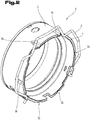
- Fig. 2 shows a cross-section of the connector 2, the cutting line being selected so that a locking element 6 built into the connector 2 for securing the connector 2 and the mating connector 3 to one another can be seen.
- the locking element 6 is constructed in such a way that it can be easily activated and deactivated so that the plug connector 2 and the mating plug connector 3 can be separated from one another or connected to one another as required.
- the locking element 6 can be brought into a latching position in which the connector 2 and the mating connector 3 are secured to one another. Furthermore, the locking element 6 can be brought into a release position in which the mating connector 3 can be inserted into the connector 2 or removed from it.
- a reinforcing element 7 is inserted into the connector body 5, which reinforcement element serves to improve the rigidity of the connector body 5.
- the reinforcing element 7 can as in Fig. 2 can be clearly seen as a sleeve segment, and therefore have an intermediate piece that is open over the circumference.
- the reinforcing element 7 can be designed as a sleeve and therefore have a closed circumference.
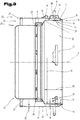
- Fig. 3 shows a section through the connector assembly 1 along a central longitudinal axis 8 of the connector 2.
- the plug connector 2 can comprise, in addition to the connector body 5, a plug seal 9 which is received in the connector body 5.
- the plug seal 9 is used to be able to adequately seal the plug connector in the mated state with the mating plug connector 3.
- an inner jacket section 10 is formed on the connector body 5, which surrounds the central longitudinal axis 8 of the connector 2 in the form of a sleeve.
- the inner jacket section 10 is a rotationally symmetrical hollow cylinder.
- the inner jacket section 10 has an inside jacket surface 11 and an outside jacket surface 12.
- the inner jacket section 10 is surrounded by an outer jacket section 13, which is also designed to be rotationally symmetrical with respect to the central longitudinal axis 8.
- the inner jacket section 10 is connected to the outer jacket section 13 at a first end section 14 by means of a first end wall section 15.
- the first end wall section 15 can be designed in various ways. In particular, it can be provided that the first end wall section 15 is designed in the form of a fold, the outer jacket section 13 being turned over by approximately 180 ° with respect to the inner jacket section 10, whereby the outer jacket section 13 is arranged surrounding the inner jacket section 10.
- the outer jacket section 13 also has an inside jacket surface 16 and an outside jacket surface 17.
- the inner jacket section 10 is delimited by its inner jacket surface 11 and the outer jacket surface 12, which results in a wall thickness 18 of the inner jacket section 10.
- the outer casing section 13 is also delimited by an inner casing surface 16 and an outer casing surface 17, which results in a wall thickness 19 of the outer casing section 13.
- the inner jacket section 10 is designed stepped in the illustrated embodiment. It can be provided that the inner jacket section 10 on the opposite side of the first end section 14 of the plug connector 2 is followed by a sealing receptacle 20, which is also formed in the connector body 5. A plug seal 9 can be received in such a seal receptacle 20. Furthermore, it can be provided that a third jacket section 21 adjoins the seal receptacle 20, which, together with the outer jacket section 13, forms an annular space 22 for receiving the tube 4.
- the outer jacket section 13 and the third jacket section 21 are open to one another at a second end section 23 of the plug connector 2, as a result of which a tube receiving side 24 of the connector body 5 results.
- the third jacket section 21 has a bevel 25 in the region of the second end section 23, which bevel is formed on the tube receiving side 24.
- a bevel 25 has the advantage that the pipe 4 or a sealing element used to seal the pipe 4 can easily be pushed into the annular space 22 in the pushing-in direction 26.
- the outer jacket section 13 has such a bevel 27 so that the tube 4 can also be easily pushed into the annular space 22. The tube 4 can then be pressed together with the connector body 5 so that the two components form a unit.
- the bevels 25, 27 can be implemented, for example, by flanging with corresponding radii or by widening and are preferably formed during the deep-drawing process.
- the connector body 5 is preferably produced in a deep-drawing process, all wall thicknesses of the jacket sections of the connector body 5 being approximately the same.
- the seal receptacle 20 can also be expedient for the seal receptacle 20 to have an end wall 28 which adjoins the third jacket section 21.
- a receiving trough for the plug seal 9 can be formed by the end wall 28.
- the inner jacket section 10 has an outer diameter 30 and an axial extension 29.
- An inner diameter 31 of the reinforcement element 7 is preferably selected to be approximately the same size as the outer diameter 30 of the inner jacket section 10.
- the plug connector 2 In the area of the inner jacket section 10, the plug connector 2 has a receiving space 32.
- the receiving space 32 is surrounded by the inner jacket section 10 and serves to receive a part of the mating connector 3.
- the connector body 5 has a plurality of passage openings 33 which are spaced apart from one another in the circumferential direction and which are also arranged in the area of the inner jacket section 10. In the latching position of the locking element 6, which it assumes in the inserted and locked state, the locking element 6 protrudes through the respective passage opening 33 into the receiving space 32. In these sections, the locking element 6 interacts with a locking surface of a locking shoulder of the mating connector 3.
- the reinforcement element 7 has a recess 34 which corresponds to one of the passage openings 33 and thus the locking element 6 can be passed through the reinforcement element 7.
- a first type of passage openings 33 'and a second type of passage openings 33 are formed.
- a first type of recesses 34' and a second type of recesses 34" can be formed in a corresponding manner.
- the recess 34 ′′ of the reinforcement element 7 and the passage opening 33 ′′ of the connector body 5 at least partially have the same outer contour or are arranged congruently with one another.
- the passage opening 33 'and the recess 34' can be designed to be completely congruent, resulting in a common passage opening 35.
- one or more beads 36 are made in the outer jacket section 13 of the connector body 5, by means of which the reinforcing element 7 can be clamped in the space between the inner jacket section 10 and the outer jacket section 13.
- the reinforcing element 7 can be fixed in the radial direction by the beads 36 or, if necessary, also held in position in the axial direction by a radial clamping.
- the beads 36 can also contribute to increasing the stability of the outer jacket section 13.
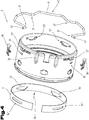
- Fig. 4 shows an exploded view of the individual components of the connector 2, again with the same reference numerals or component designations for the same parts as in the preceding Figures 1 to 3 be used.
- Fig. 4 shows an exploded view of the individual components of the connector 2, again with the same reference numerals or component designations for the same parts as in the preceding Figures 1 to 3 be used.
- the locking element 6 can have, for example, four latching areas 37 which are designed to protrude through the through openings 33 of the connector body 5.
- the latching areas 37 are therefore designed as inwardly projecting V-shaped elements.
- the connector 2 also comprises holding elements 38 which are inserted into a holding element receptacle 39 and serve to secure the locking element 6.
- the reinforcing element 7 is in the Fig. 4 shown already prefabricated, wherein it is pre-bent and the recesses 34 have already been made in the reinforcing element 7.
- the reinforcing element 7 can be designed as a sleeve segment can.
- the two recesses 34 ′′ are designed in the shape of a slot.
- the two recesses 34 ′ can have exactly the same outer contour as the passage openings 33 ′ that correspond to them.
- the recesses 34 are not or only partially made in the prefabricated reinforcing element 7 and that these are only formed when the reinforcing element 7 is inserted into the connector body 5.
- the reinforcing element 7 can be punched together with the connector body 5 in the inserted state.
- the reinforcement element 7 has a higher strength than the connector body 5. Since the reinforcement element 7 does not have to be reshaped as much as the connector body 5, it can be provided that that the connector body 5 is made of a first material and the reinforcing element 7 is made of a second material, the second material having a lower deformability than the first material.
- the connector body 5 is manufactured from a flat sheet metal material by reshaping, in particular by deep drawing.
- the recesses 34 and 39 arranged in the circumference of the connector body 5 can be punched in during the deep-drawing process.
- the reinforcing element 7 can also be brought into its shape by reshaping.
- the passage openings 33 or the corresponding recess 34 are only produced in a subsequent punching process when the reinforcing element 7 has already been inserted in the connector body 5.
- the recess 34 and the passage opening 33 can be produced in the form of a common passage opening 35, the reinforcing element 7 and the connector body 5 wedging into one another in a form-fitting manner through the punching process, thereby improving the axial positioning of the reinforcing element 7.
- the recesses 34 are made in the reinforcing element 7 before they are inserted into the connector body 5.
- the reinforcing element 7 can be pushed into the connector body 5 in the push-in direction 26 and inserted into it. It is conceivable here for the reinforcement element 7 to be pushed into a rebate area 40 which is formed in the connector body 5 in the area of the end wall section 15. A narrow slot can be formed radially through this fold area 40, into which the reinforcing element 7 can be pushed. In particular, it can be provided that the reinforcement element 7 is clamped in the rebate area 40.
- the beads 36 can serve for the axial and radial positioning and fixing of the reinforcing element 7. These can be introduced into the connector body 5 in advance. In an alternative manufacturing variant, the beads 36 can also be introduced into the connector body 5 after the reinforcement element 7 has been inserted, in order to be able to clamp the reinforcement element 7.
- the locking element 6 can be inserted into the connector body 5 and then the holding elements 38 for securing the locking element 6 can be inserted into the connector body 5.
- the locking element 6 has a holding area 41 on which it can be gripped in order to be able to be inserted into the connector body 5 and to be able to be moved between the latching position and the release position.
- Fig. 5 shows a perspective view of the connector 2, the locking element 6 being in the latching position.
- Fig. 6 shows a detailed view of the locking element 6 which is in the locking position.
- Fig. 7 shows a perspective view of the connector 2, the locking element 6 being in the release position.
- Fig. 8 shows a detailed view of the locking element 6 which is in the release position.
- the latching position of the locking element 6 is particularly good in a synopsis of the Fig. 5 and 6th and the release position of the locking element 6 in a synopsis of the Fig. 7 and 8th evident.
- the locking areas 37 protrude into the receiving space 32 and the mating connector 3 is axially secured relative to the connector 2.
- the latching areas 37 do not protrude into the receiving space 32 and the mating connector 3 is axially displaceable relative to the connector 2.
- the recess 34 in the reinforcing element 7 is designed in the form of a slot, the slot having a width which corresponds approximately to the diameter of the locking element 6.
- the locking element 6 can thereby be axially fixed.
- the locking element 6 If one now pulls the locking element 6 on the holding area 41 in the radial direction away from the longitudinal axis of the connector 2, the locking areas 37 are pulled out of the receiving space 32 due to the geometry of the locking element 6. In particular, the locking element 6 is moved radially outward until it is in the release position according to the Fig. 7 and 8th is brought.
- a guide pin 42 of the locking element 6 strikes the holding element 38 and is thereby deflected axially, so that the locking element 6 moves into the release position.
- a bevel 43 is formed in the holding element 38, through which an axial movement is initiated in the locking element 6 in the event of a radial pull on the holding area 41.
- the locking element 6 can be released, the guide pin 42 on the connector body 5 or, as in FIG Fig. 8 particularly clearly visible, rests on the reinforcing element 7 and thus remains in the release position, the locking element 6 being pretensioned.
- the locking element 6 In order to move the locking element 6 from the release position back into the locking position, the locking element 6 can be shifted slightly axially and the applied bias of the locking element 6 automatically moves it back into the locking position as soon as it plunges into the recesses 34 'of the locking element 6 can.
- Fig. 9 shows the holding element 38 in a perspective view.
- Fig. 10 shows a section through the connector in the area of the holding element.
- the function of the holding element or its structure is based on a synopsis of the Figures 7 , 8th , 9 and 10 described.
- the holding element 38 is designed as a formed sheet metal part and therefore has a constant wall thickness. Furthermore, it is provided that the holding element 38 is designed in one piece.
- the holding element 38 has a fastening section 44 which is designed in the form of a tab 45.
- the fastening section 44 can be inserted into the holding element receptacle 39 of the connector body 5.
- a holding section 46 is formed at a first longitudinal end, which spans the passage opening 33 ′ and serves to secure the locking element 6.
- the fastening section 44 can be formed directly adjoining the holding section 46.
- the fastening section 44 can be formed by the tab 45, the sheet metal being folded over at an angle between 90 ° and 240 °, in particular between 140 ° and 210 °, preferably between 175 ° and 185 °.
- a support section 48 is formed on the side of the tab 45 opposite the holding section 46.
- the support section 48 serves in particular to be able to offer a counter-support for the holding section 46.
- the torque introduced into the holding element 38 in the holding section 46 can be absorbed by the support section 48.
- the holding section 46 rests in a support area 49 on the connector body 5, a support tab 50 being formed by means of which the holding section 46 can be positioned at a distance 51 from the connector body 5.
- the support tab 50 can be arranged, for example, at a right angle to the holding section 46.
- the holding section 46 is arranged parallel to the outer jacket section 13 in the installed state of the holding element 38.
- the support section 48 can be arranged in a support bracket 52 to the outer jacket section 13. In a support area 53, the support section 48 can rest on the outer jacket section 13.
- the holding element 38 in the area of the fastening section 44 can have a fastening nose 54 on each of the two longitudinal sides, which is projecting relative to the fastening section 44.
- the fastening nose 54 is preferably designed in such a way that it engages behind the outer jacket section 13 of the connector body 5 in a form-fitting manner in the region of the holding element receptacle 39 and thus enables the holding element 38 to be fastened to the connector body 5 in a form-fitting manner.
- the holding element 38 is preferably designed in such a way that, in the installed state, it is pretensioned between the fastening section 44 and the holding section 46 or support section 48 due to its elasticity and its resilient properties. It can thereby be achieved that the holding element 38 can be fastened to the connector body 5 in a stable manner.
- a longitudinal slot 55 extending in the longitudinal direction of the holding element 38 is formed in the holding element 38.
- the longitudinal slot 55 is formed in particular in the area of the fastening section 44. Because the holding element 38 is slit longitudinally, it can be compressed, viewed in its width 56, in order to be able to insert the holding element 38 into the holding element receptacle 39.
- the fastening lugs 54 can thereby be pressed inward to such an extent that they can be passed through the opening of the holding element receptacle 39 and, after the holding element 38 has been resiliently restored, they can engage behind in a form-fitting manner.
- an insert bevel 57 is formed in the area of the fastening section 44.
- the holding element 38 can be compressed in its width 56 when it is pressed into the holding element receptacle 39.
- Connector assembly 29 Axial extension of the first jacket section 2 Connectors 3 Mating connector 30th Outside diameter of the first jacket section 4th pipe 5 Connector body 31 Inside diameter 6th Locking element 32 Recording room 7th Reinforcement element 33 Passage opening 8th Longitudinal axis of the connector 34 Recess 9 Connector seal 35 common passage opening 10 inner jacket section 36 Bead 11 inner jacket surface 37 Rest area 12th outer jacket surface 38 Retaining element 13th outer jacket section 39 Holding element receptacle 14th first end section connector 40 Folding area 15th Front wall section 41 Holding area 16 inner jacket surface 42 Guide pin 17th outer jacket surface 43 bevel 18th Wall thickness of the first jacket section 44 Fastening section 19th Wall thickness of the second jacket section 45 Tab 46 Holding section 20th Sealing receptacle connector 47 angle 48 Support section 21 Third jacket section 49 Support area holding section 22nd Annulus 50 Support bracket 23 second end section connector 51 distance 52 Support bracket 24 Pipe receiving side 53 Support area support section 25th bevel 54 Fastening nose 26th Direction of insertion
Description
Die Erfindung betrifft einen Steckverbinder zum Verbinden von Leitungen für flüssige oder gasförmige Medien.The invention relates to a connector for connecting lines for liquid or gaseous media.
Aus der
Der Steckverbinder der
Aufgabe der vorliegenden Erfindung war es, die Nachteile des Standes der Technik zu überwinden und eine Vorrichtung zur Verfügung zu stellen, welche bei guter Funktionalität im verbauten Zustand auch einfach herzustellen ist.The object of the present invention was to overcome the disadvantages of the prior art and to provide a device which is easy to manufacture with good functionality in the installed state.
Diese Aufgabe wird durch eine Vorrichtung gemäß dem Anspruch 1 gelöst.This object is achieved by a device according to claim 1.
Die erfindungsgemäße Vorrichtung ist ein Steckverbinder für ein Kraftfahrzeug, mit einem Verbinderkörper, welcher Verbinderkörper zumindest einen hülsenförmigen, im Querschnitt eine zentrale Längsachse des Steckverbinders umgebenden, äußeren Mantelabschnitt aufweist. Im äußeren Mantelabschnitt sind zumindest zwei Durchtrittsöffnungen ausgebildet, welche zur Aufnahme eines Endabschnittes eines Arretierungselementes vorgesehen sind. Das Arretierungselement ist zum Sichern des Steckverbinders relativ zu einem Gegensteckverbinder vorgesehen, wobei in zumindest einer der Durchtrittsöffnungen ein Haltelement zum Sichern des Arretierungselementes angeordnet ist. Das Haltelement ist als Blechumformteil ausgebildet und für beide Durchtrittsöffnungen ist ein eigenes Haltelement vorgesehen.The device according to the invention is a connector for a motor vehicle, with a connector body, which connector body has at least one sleeve-shaped cross section has a central longitudinal axis of the connector surrounding, outer jacket portion. In the outer jacket section, at least two passage openings are formed, which are provided for receiving an end section of a locking element. The locking element is provided for securing the plug connector relative to a mating connector, a holding element for securing the locking element being arranged in at least one of the passage openings. The holding element is designed as a formed sheet metal part and a separate holding element is provided for both passage openings.
Von Vorteil an der erfindungsgemäßen Vorrichtung ist, dass das Halteelement in einem Produktionsprozess zur Serienfertigung einfach hergestellt werden kann. Insbesondere ein Halteelement, welches als Blechumformteil ausgebildet ist, kann bei hoher Festigkeit und hoher Steifigkeit eine möglichst geringe Masse aufweisen. Dadurch dass für beide Durchtrittsöffnungen ein eigenes Halteelement vorgesehen ist, kann dieses darüber hinaus einfach in den Verbinderkörper des Steckverbinders eingesetzt werden.The advantage of the device according to the invention is that the holding element can be easily manufactured in a production process for series production. In particular, a holding element which is designed as a formed sheet metal part can have the lowest possible mass with high strength and high rigidity. Because a separate holding element is provided for both passage openings, this can also be easily inserted into the connector body of the plug connector.
Weiters kann es zweckmäßig sein, dass der Verbinderkörper einen Ringraum aufweist, der zwischen einem hülsenförmigen, im Querschnitt die zentrale Längsachse umgebenden, inneren Mantelabschnitt und dem äußeren Mantelabschnitt des Steckverbinders liegt, wobei der innere Mantelabschnitt vom äußeren Mantelabschnitt umgeben ist und der innere Mantelabschnitt des Verbinderkörpers mit dem äußeren Mantelabschnitt an einem ersten Endabschnitt durch einen ersten Stirnwandabschnitt verbunden ist und die Mantelabschnitte an einem zweiten Endabschnitt offen zueinander sind, wobei die zumindest zwei Durchtrittsöffnungen sowohl den inneren Mantelabschnitt als auch den äußeren Mantelabschnitt durchdringen. Insbesondere ein derartig ausgebildeter Verbinderkörper weist eine gute Funktionalität zum Einsatz im erfindungsgemäßen Steckverbinder auf.Furthermore, it can be expedient for the connector body to have an annular space which lies between a sleeve-shaped inner jacket section surrounding the central longitudinal axis in cross section and the outer jacket section of the connector, the inner jacket section being surrounded by the outer jacket section and the inner jacket section of the connector body is connected to the outer jacket section at a first end section by a first end wall section and the jacket sections are open to one another at a second end section, the at least two passage openings penetrating both the inner jacket section and the outer jacket section. In particular, a connector body designed in this way has good functionality for use in the connector according to the invention.
Ferner kann vorgesehen sein, dass das Haltelement einen Befestigungsabschnitt aufweist, mittels welchem das Haltelement in einer im äußeren Mantelabschnitt angeordneten Halteelementaufnahme formschlüssig aufgenommen ist. Von Vorteil ist hierbei, dass das Halteelement einfach in die Halteelementaufnahme eingesetzt werden kann, wobei das Halteelement nicht durch eine stoffschlüssige Verbindung, wie etwa einer Schweißverbindung mit dem Verbinderkörper verbunden werden muss. Somit kann der Zusammenbau des Steckverbinders vereinfacht und dadurch auch beschleunigt werden.Furthermore, it can be provided that the holding element has a fastening section, by means of which the holding element is positively received in a holding element receptacle arranged in the outer jacket section. The advantage here is that the holding element can be easily inserted into the holding element receptacle, the holding element not having to be connected to the connector body by a material connection, such as a welded connection. The assembly of the connector can thus be simplified and thereby also accelerated.
Darüber hinaus kann vorgesehen sein, dass das Halteelement einen Halteabschnitt aufweist, welcher die Durchtrittsöffnung überspannt. Von Vorteil ist hierbei, dass durch den Halteabschnitt das Arretierungselement im Verbinderkörper gehalten werden kann.In addition, it can be provided that the holding element has a holding section which spans the passage opening. The advantage here is that the locking element can be held in the connector body by the holding section.
Vorteilhaft ist auch eine Ausprägung, gemäß welcher vorgesehen sein kann, dass das Haltelement einen Stützabschnitt aufweist, welcher an der zum Halteabschnitt gegenüberliegenden Seite des Befestigungsabschnittes angeordnet ist. Der Stützanschnitt kann als Gegenstütze zum Halteabschnitt wirken und das Halteelement gegen Verdrehung gesichert im Verbinderkörper aufnehmen zu können. Insbesondere kann dabei vorgesehen sein, dass das Halteelement im Bereich des Befestigungsabschnittes durch die formschlüssige Verbindung mit dem Verbinderkörper in Richtung Zentrum des Verbinderkörpers gezogen wird und dass sich das Halteelement im Bereich des Halteabschnittes und im Bereich des Stützabschnittes, welche rechts bzw. links der Befestigungsabschnitte angeordnet sind, am Verbinderkörper abstützen kann, wodurch das Halteelement positionsstarr und verdrehstarr am Verbinderkörper aufgenommen ist.An embodiment is also advantageous, according to which it can be provided that the holding element has a support section which is arranged on the side of the fastening section opposite to the holding section. The support section can act as a counter-support for the holding section and can accommodate the holding element in the connector body in a manner that is secured against rotation. In particular, it can be provided that the holding element in the area of the fastening section is pulled through the form-fitting connection with the connector body in the direction of the center of the connector body and that the holding element is in the area of the holding section and in the area of the support section, which is arranged to the right and left of the fastening sections are, can be supported on the connector body, whereby the holding element is received rigidly in position and torsionally rigid on the connector body.
Gemäß einer Weiterbildung ist es möglich, dass der Halteabschnitt in einem Auflagebereich eine Auflagelasche aufweist mittels welcher der Halteabschnitt in einem Abstand zur Durchtrittsöffnung angeordnet ist und diese überspannt. Durch die Auflagelasche kann erreicht werden, dass der Halteabschnitt in einem gewissen Abstand von der Durchtrittsöffnung angeordnet ist und somit das Arretierungselement von der Raststellung in die Freigabestellung bewegt werden kann.According to a further development, it is possible for the holding section to have a support tab in a support area, by means of which the holding section is arranged at a distance from the passage opening and spans it. By means of the support tab it can be achieved that the holding section is arranged at a certain distance from the passage opening and thus the locking element can be moved from the latching position into the release position.
Ferner kann es zweckmäßig sein, dass das Haltelement im Bereich des Befestigungsabschnittes zumindest eine Befestigungsnase zum Hintergreifen der Halteelementaufnahme aufweist. Dadurch kann erreicht werden, dass das Halteelement formschlüssig in der Halteelementaufnahme aufgenommen werden kann. Insbesondere kann durch die Befestigungsnase ein fester Sitz des Halteelementes in der Halteelementaufnahme erreicht werden.Furthermore, it can be expedient for the holding element to have at least one fastening nose in the area of the fastening section for engaging behind the holding element receptacle. It can thereby be achieved that the holding element can be received in the holding element receptacle in a form-fitting manner. In particular, a tight fit of the holding element in the holding element receptacle can be achieved by the fastening nose.
Darüber hinaus kann vorgesehen sein, dass das Haltelement im Bereich des Befestigungsabschnittes einen in etwa mittig angeordneten Längsschlitz aufweist. Von Vorteil ist hierbei, dass dadurch das Halteelement zusammengedrückt werden kann sodass sich die Befestigungsnasen aufeinander zu bewegen und der Halteabschnitt in die Halteelementaufnahme eingesetzt werden kann.In addition, it can be provided that the holding element has an approximately centrally arranged longitudinal slot in the area of the fastening section. The advantage here is that thereby the holding element can be compressed so that the fastening lugs move towards one another and the holding section can be inserted into the holding element receptacle.
Weiters kann vorgesehen sein, dass das Haltelement im Bereich des Halteabschnittes eine Abschrägung aufweist. Von Vorteil ist hierbei, dass durch die Abschrägung erreicht werden kann, dass sich das Halteelement im Befestigungsabschnitt nach außen hin verjüngt, wodurch es gut in den Halteabschnitt des Verbinderkörpers eingesetzt werden kann.Furthermore, it can be provided that the holding element has a bevel in the region of the holding section. The advantage here is that it can be achieved by the bevel that the holding element tapers outward in the fastening section, so that it can be easily inserted into the holding section of the connector body.
Gemäß einer besonderen Ausprägung ist es möglich, dass das Haltelement im Bereich des Befestigungsabschnittes eine Lasche aufweist, wobei das Blech in einem Winkel zwischen 90° und 240°, insbesondere zwischen 140° und 210°, bevorzugt zwischen 175° und 185° umgeschlagen ist. Insbesondere kann dadurch erreicht werden, dass das Halteelement einteilig als Blechumformteil geformt werden kann.According to a particular embodiment, it is possible for the holding element to have a tab in the area of the fastening section, the sheet metal being folded over at an angle between 90 ° and 240 °, in particular between 140 ° and 210 °, preferably between 175 ° and 185 °. In particular, it can thereby be achieved that the holding element can be formed in one piece as a sheet metal part.
Zum besseren Verständnis der Erfindung wird diese anhand der nachfolgenden Figuren näher erläutert.For a better understanding of the invention, it is explained in more detail with reference to the following figures.
Es zeigen jeweils in stark vereinfachter, schematischer Darstellung:
- Fig. 1
- eine perspektivische Darstellung einer Ausführungsvariante einer Steckerbaugruppe in einem Viertelschnitt;
- Fig. 2
- ein Querschnitt eines Ausführungsbeispiels des Steckverbinders mit Schnittführung im Bereich eines Arretierungselementes;
- Fig. 3
- eine Schnittdarstellung des Steckverbinders mit Schnittführung entlang einer zentralen Längsachse des Steckverbinders;
- Fig. 4
- eine Explosionsdarstellung des Steckverbinders;
- Fig. 5
- eine perspektivische Ansicht der Steckverbinder, wobei sich das Arretierungselement in einer Raststellung befindet;
- Fig. 6
- eine Detailansicht des Arretierungselementes, wobei sich das Arretierungselement in einer Raststellung befindet;
- Fig. 7
- eine perspektivische Ansicht des Steckverbinders, wobei sich das Arretierungselement in einer Freigabestellung befindet;
- Fig. 8
- eine Detailansicht des Arretierungselementes, wobei sich das Arretierungselement in einer Freigabestellung befindet;
- Fig. 9
- eine perspektivische Ansicht des Halteelementes;
- Fig. 10
- einen Schnitt durch den Steckverbinder im Bereich des Halteelementes.
- Fig. 1
- a perspective view of an embodiment of a connector assembly in a quarter section;
- Fig. 2
- a cross section of an embodiment of the connector with a cut in the area of a locking element;
- Fig. 3
- a sectional view of the connector with a section taken along a central longitudinal axis of the connector;
- Fig. 4
- an exploded view of the connector;
- Fig. 5
- a perspective view of the connector, wherein the locking element is in a latching position;
- Fig. 6
- a detailed view of the locking element, wherein the locking element is in a latching position;
- Fig. 7
- a perspective view of the connector, wherein the locking element is in a release position;
- Fig. 8
- a detailed view of the locking element, wherein the locking element is in a release position;
- Fig. 9
- a perspective view of the holding element;
- Fig. 10
- a section through the connector in the area of the holding element.
Einführend sei festgehalten, dass in den unterschiedlich beschriebenen Ausführungsformen gleiche Teile mit gleichen Bezugszeichen bzw. gleichen Bauteilbezeichnungen versehen werden, wobei die in der gesamten Beschreibung enthaltenen Offenbarungen sinngemäß auf gleiche Teile mit gleichen Bezugszeichen bzw. gleichen Bauteilbezeichnungen übertragen werden können. Auch sind die in der Beschreibung gewählten Lageangaben, wie z.B. oben, unten, seitlich usw. auf die unmittelbar beschriebene sowie dargestellte Figur bezogen und sind diese Lageangaben bei einer Lageänderung sinngemäß auf die neue Lage zu übertragen.By way of introduction, it should be noted that in the differently described embodiments, the same parts are provided with the same reference symbols or the same component names, whereby the disclosures contained in the entire description can be transferred accordingly to the same parts with the same reference symbols or the same component names. The position details chosen in the description, e.g. above, below, to the side, etc., refer to the figure immediately described and shown and these position details are to be transferred accordingly to the new position in the event of a change in position.
Weiters ist schematisch ein Rohr 4 dargestellt, an welches der Steckverbinder 2 gekoppelt sein kann. Das Rohr 4 kann beispielsweise ein starres Element, wie etwa ein Kunststoffrohr sein. In einer andern Ausführungsvariante kann das Rohr 4 als flexible Leitung aus einem Gummiwerkstoff ausgebildet sein.Furthermore, a
Der Steckverbinder 2 umfasst einen Verbinderkörper 5, welcher vorzugsweise als einteiliges Umformteil, etwa als Tiefziehteil, insbesondere aus einem Edelstahlblech gebildet ist.The
Die Steckerbaugruppe 1 wird vorzugsweise in einem Kraftfahrzeug, insbesondere in einem straßengebundenen Kraftfahrzeug mit Verbrennungsmotor, wie etwa einem PKW oder einem LKW eingesetzt.The connector assembly 1 is preferably used in a motor vehicle, in particular in a road motor vehicle with an internal combustion engine, such as a car or a truck.
Natürlich ist es auch denkbar, dass die Steckerbaugruppe 1 in einer sonstigen Anwendung mit Verbrennungsmotor verwendet wird. Dies kann beispielsweise der Einsatz der Steckerbaugruppe 1 in einem stationären Aggregat, in einem Schiffsmotor, in einem Flugzeugmotor, in einer Baumaschine usw. sein.Of course, it is also conceivable that the connector assembly 1 is used in another application with an internal combustion engine. This can be, for example, the use of the connector assembly 1 in a stationary unit, in a ship engine, in an aircraft engine, in a construction machine, etc.
Im Speziellen kann die Steckerbaugruppe 1 zum Verbinden verschiedener Bauteile der Frischluftzuführung zum Verbrennungsmotor eingesetzt werden. Beispielsweise kann vorgesehen sein, dass der Steckverbinder 2 mit dem entsprechenden Gegensteckverbinder 3 zur Verbindung zweier Teile im Ansaugbereich eines Turboladers vorgesehen ist. Weiters kann beispielsweise auch vorgesehen sein, dass eine derartige Steckerbaugruppe 1 in der vom Turbolader abgehenden Druckseite zur Verbindung zweier Bauteile eingesetzt wird.In particular, the connector assembly 1 can be used to connect different components of the fresh air supply to the internal combustion engine. For example, it can be provided that the
Das Arretierungselement 6 ist derart konstruiert, dass es leicht aktiviert und deaktiviert werden kann, sodass der Steckverbinder 2 und der Gegensteckverbinder 3 bedarfsweise voneinander getrennt bzw. miteinander verbunden werden können. Das Arretierungselement 6 kann in eine Raststellung gebracht werden, in welcher der Steckverbinder 2 und der Gegensteckverbinder 3 zueinander gesichert sind. Weiters kann das Arretierungselement 6 in eine Freigabestellung gebracht werden, in welcher der Gegensteckverbinder 3 in den Steckverbinder 2 eingesetzt oder aus diesem herausgenommen werden kann.The locking
Wie aus
Wie in
Wie in
Der innere Mantelabschnitt 10 weist eine innenliegende Mantelfläche 11 und eine außenliegende Mantelfläche 12 auf. Den inneren Mantelabschnitt 10 umgibt ein äußerer Mantelabschnitt 13, welcher ebenfalls bezüglich der zentralen Längsachse 8 rotationssymmetrisch ausgebildet ist. Der innere Mantelabschnitt 10 ist mit dem äußeren Mantelabschnitt 13 an einem ersten Endabschnitt 14 mittels eines ersten Stirnwandabschnittes 15 verbunden. Der erste Stirnwandabschnitt 15 kann verschiedenartig ausgebildet sein. Insbesondere kann vorgesehen sein, dass der erste Stirnwandabschnittes 15 in Form eines Falzes ausgebildet ist, wobei der äußere Mantelabschnitt 13 gegenüber dem inneren Mantelabschnitt 10 um etwa 180° umgeschlagen ist, wodurch der äußere Mantelabschnitt 13 den inneren Mantelabschnitt 10 umgebend angeordnet ist.The
Gleich wie der innere Mantelabschnitt 10 weist auch der äußere Mantelabschnitt 13 eine innenliegende Mantelfläche 16 und eine außenliegende Mantelfläche 17 auf.Like the
Der innere Mantelabschnitt 10 wird durch seine innenliegende Mantelfläche 11 und die außenliegende Mantelfläche 12 begrenzt, wodurch sich eine Wandstärke 18 des inneren Mantelabschnittes 10 ergibt. Der äußere Mantelabschnitt 13 wird ebenfalls durch eine innenliegende Mantelfläche 16 und eine außenliegende Mantelfläche 17 begrenzt, wodurch sich eine Wandstärke 19 des äußeren Mantelabschnittes 13 ergibt.The
Der innere Mantelabschnitt 10 ist im dargestellten Ausführungsbeispiel abgestuft ausgeführt. Dabei kann vorgesehen sein, dass an den inneren Mantelabschnitt 10 an der gegenüberliegenden Seite des ersten Endabschnittes 14 des Steckverbinders 2, eine Dichtungsaufnahme 20 anschließt, welche ebenfalls im Verbinderkörper 5 ausgeformt ist. In einer derartigen Dichtungsaufnahme 20 kann eine Steckerdichtung 9 aufgenommen sein. Weiters kann vorgesehen sein, dass an die Dichtungsaufnahme 20 ein dritter Mantelabschnitt 21 anschließt, welcher zusammen mit dem äußeren Mantelabschnitt 13 einen Ringraum 22 zur Aufnahme des Rohres 4 bildet.The
Der äußere Mantelabschnitt 13 und der dritte Mantelabschnitt 21 sind an einem zweiten Endabschnitt 23 des Steckverbinders 2 offen zueinander, wodurch sich eine Rohraufnahmeseite 24 des Verbinderkörpers 5 ergibt.The
Es kann vorgesehen sein, dass der dritte Mantelabschnitt 21 im Bereich des zweiten Endabschnittes 23 eine Abschrägung 25 aufweist, welche an der Rohraufhahmeseite 24 ausgebildet ist. Eine derartige Abschrägung 25 bringt den Vorteil mit sich, dass das Rohr 4 oder ein zur Abdichtung des Rohres 4 verwendetes Dichtungselement leicht in Einschieberichtung 26 in den Ringraum 22 eingeschoben werden kann. Darüber hinaus kann auch vorgesehen sein, dass der äußere Mantelabschnitt 13 eine derartige Abschrägung 27 aufweist, sodass auch das Rohr 4 leicht in den Ringraum 22 eingeschoben werden kann. Anschließend kann das Rohr 4 mit dem Verbinderkörper 5 verpresst werden, sodass die beiden Bauteile eine Einheit bilden.It can be provided that the
Die Abschrägungen 25, 27 können beispielsweise durch Umbördelungen mit entsprechenden Radien oder durch Aufweitungen realisiert werden und werden vorzugsweise während des Tiefziehvorganges ausgeformt.The
Bevorzugt wird der Verbinderkörper 5 in einem Tiefziehverfahren hergestellt, wobei sämtliche Wandstärken der Mantelabschnitte des Verbinderkörpers 5 in etwa gleich groß sind.The
Wie in der Ansicht in
Der innere Mantelabschnitt 10 weist einen Außendurchmesser 30 und eine axiale Erstreckung 29 auf. Ein Innendurchmesser 31 des Verstärkungselementes 7 ist vorzugsweise in etwa gleich groß gewählt, wie der Außendurchmesser 30 des inneren Mantelabschnittes 10.The
Im Bereich des inneren Mantelabschnittes 10 weist der Steckverbinder 2 einen Aufnahmeraum 32 auf. Der Aufnahmeraum 32 wird vom inneren Mantelabschnitt 10 umgeben und dient zur Aufnahme eines Teils des Gegensteckverbinders 3.In the area of the
Der Verbinderkörper 5 weist mehrere, in Umfangsrichtung voneinander beabstandete Durchtrittsöffnungen 33 auf, welche ebenfalls im Bereich des inneren Mantelabschnittes 10 angeordnet sind. In der Raststellung des Arretierungselementes 6, welche diese im eingesteckten und verrasteten Zustand einnimmt, ragt das Arretierungselement 6 durch die jeweilige Durchtrittsöffnung 33 in den Aufnahmeraum 32. In diesen Abschnitten wirkt das Arretierungselement 6 mit einer Verriegelungsfläche einer Rastschulter des Gegensteckverbinders 3 zusammen.The
Aus
Insbesondere kann vorgesehen sein, dass die Ausnehmung 34" des Verstärkungselementes 7 und die Durchtrittsöffnung 33" des Verbinderkörpers 5 zumindest teilweise dieselbe Außenkontur aufweisen bzw. deckungsgleich zueinander angeordnet sind.In particular, it can be provided that the
Insbesondere können die Durchtrittsöffnung 33' und die Ausnehmung 34' zur Gänze deckungsgleich ausgebildet sein, wodurch sich eine gemeinsame Durchtrittsöffnung 35 ergibt.In particular, the passage opening 33 'and the recess 34' can be designed to be completely congruent, resulting in a
Wie aus einer Zusammenschau der
In
Das Verstärkungselement 7 ist in der
In einer weiteren nicht dargestellten Ausführungsvariante kann auch vorgesehen sein, dass die Ausnehmungen 34 nicht oder nur teilweise in das vorgefertigte Verstärkungselement 7 eingebracht sind und dass diese erst ausgebildet werden, wenn das Verstärkungselement 7 in den Verbinderkörper 5 eingesetzt ist. Dabei kann das Verstärkungselement 7 im eingesetzten Zustand zusammen mit dem Verbinderkörper 5 gestanzt werden.In a further embodiment variant, not shown, it can also be provided that the
Um eine Versteifung des Verbinderkörpers 5 durch das Verstärkungselement 7 zu erreichen, kann vorgesehen sein, dass das Verstärkungselement 7 eine höhere Festigkeit aufweist als der Verbinderkörper 5. Da das Verstärkungselement 7 nicht so stark umgeformt werden muss, wie der Verbinderkörper 5, kann vorgesehen sein, dass der Verbinderkörper 5 aus einem ersten Werkstoff und das Verstärkungselement 7 aus einem zweiten Werkstoff gefertigt ist, wobei der zweite Werkstoff eine geringere Umformfähigkeit aufweist als der erste Werkstoff.In order to achieve a stiffening of the
Im Folgenden wird der mögliche Zusammenbau des Steckverbinders 2 beschrieben. In einem ersten Verfahrensschritt wird der Verbinderkörper 5 durch Umformen, insbesondere durch Tiefziehen, aus einem ebenen Blechmaterial gefertigt. Dabei können während des Tiefziehvorganges die im Umfang des Verbinderkörpers 5 angeordneten Ausnehmungen 34 bzw. 39 eingestanzt werden.The possible assembly of the
In einem weiteren Verfahrensschritt kann das Verstärkungselement 7 ebenfalls durch Umformen in seine Form gebracht werden.In a further process step, the reinforcing
Weiters kann vorgesehen sein, dass zumindest eine der Durchtrittsöffnungen 33 bzw. die damit korrespondierende Ausnehmung 34 erst in einem folgenden Stanzvorgang hergestellt werden, wenn das Verstärkungselement 7 bereits im Verbinderkörper 5 eingelegt ist. Dadurch können die Ausnehmung 34 und die Durchtrittsöffnung 33 in Form einer gemeinsamen Durchtrittsöffnung 35 hergestellt werden, wobei durch den Stanzvorgang sich das Verstärkungselement 7 und der Verbinderkörper 5 formschlüssig ineinander verkeilen und dadurch die axiale Positionierung des Verstärkungselementes 7 verbessert wird.Furthermore, it can be provided that at least one of the
In einer Alternativvariante kann vorgesehen sein, dass die Ausnehmungen 34 bereits vor dem Einlegen in den Verbinderkörper 5 in das Verstärkungselement 7 eingebracht werden.In an alternative variant, it can be provided that the
In einem weiteren Verfahrensschritt kann das Verstärkungselement 7 in Einschieberichtung 26 in den Verbinderkörper 5 eingeschoben und in diesem eingesetzt werden. Hierbei ist es denkbar, dass das Verstärkungselement 7 in einen Falzbereich 40 eingeschoben wird, welcher im Verbinderkörper 5 im Bereich des Stirnwandabschnittes 15 ausgebildet ist. Durch diesen Falzbereich 40 kann radial ein schmaler Schlitz gebildet sein, in welchen das Verstärkungselement 7 eingeschoben werden kann. Insbesondere kann vorgesehen sein, dass das Verstärkungselement 7 im Falzbereich 40 geklemmt wird.In a further method step, the reinforcing
Zusätzlich können zur axialen und radialen Positionierung und Fixierung des Verstärkungselementes 7 die Sicken 36 dienen. Diese können schon vorab in den Verbinderkörper 5 eingebracht sein. In einer alternativen Herstellvariante können die Sicken 36 auch nach dem Einsetzen des Verstärkungselementes 7 in den Verbinderkörper 5 eingebracht werden, um das Verstärkungselement 7 klemmen zu können.In addition, the
In einem weiteren Verfahrensschritt kann das Arretierungselement 6 in den Verbinderkörper 5 eingesetzt werden und anschließend die Halteelemente 38 zur Sicherung des Arretierungselementes 6 in den Verbinderkörper 5 eingesetzt werden.In a further method step, the locking
Das Arretierungselement 6 weist einen Haltebereich 41 auf, an welchem es gegriffen werden kann, um in den Verbinderkörper 5 eingesetzt werden zu können und zwischen Raststellung und Freigabestellung bewegt werden zu können.The locking
In den
Besonders gut ist die Raststellung des Arretierungselementes 6 in einer Zusammenschau der
Wie in
Wenn man nun am Haltebereich 41 in radialer Richtung weg von der Längsachse des Steckverbinders 2 am Arretierungselement 6 anzieht, so werden aufgrund der Geometrie des Arretierungselementes 6 die Rastbereiche 37 aus dem Aufnahmeraum 32 herausgezogen. Insbesondere wird das Arretierungselement 6 soweit radial nach außen bewegt, bis es in die Freigabestellung entsprechend den
Kurz vor Erreichen der Freigabestellung trifft ein Führungszapfen 42 des Arretierungselementes 6 auf das Halteelement 38 und wird dadurch axial umgelenkt, sodass sich das Arretierungselement 6 in die Freigabestellung bewegt. Insbesondere kann vorgesehen sein, dass im Halteelement 38 eine Abschrägung 43 ausgebildet ist, durch welche bei radialem Zug am Haltebereich 41 eine axiale Bewegung in das Arretierungselement 6 eingeleitet wird. Nach erfolgreicher axialer Verschiebung kann das Arretierungselement 6 losgelassen werden, wobei der Führungszapfen 42 am Verbinderkörper 5 bzw., wie in
Um das Arretierungselement 6 aus der Freigabestellung wieder zurück in die Raststellung zu bewegen kann das Arretierungselement 6 geringfügig axial verschoben werden und durch die anliegende Vorspannung des Arretierungselementes 6 bewegt sich dieses selbstständig zurück in die Raststellung, sobald es in die Ausnehmungen 34'des Arretierungselementes 6 eintauchen kann.In order to move the
Die Ausführungsbeispiele zeigen mögliche Ausführungsvarianten, wobei an dieser Stelle bemerkt sei, dass die Erfindung nicht auf die speziell dargestellten Ausführungsvarianten derselben eingeschränkt ist, sondern vielmehr auch diverse Kombinationen der einzelnen Ausführungsvarianten untereinander möglich sind und diese Variationsmöglichkeit aufgrund der Lehre zum technischen Handeln durch gegenständliche Erfindung im Können des auf diesem technischen Gebiet tätigen Fachmannes liegt.The exemplary embodiments show possible design variants, whereby it should be noted at this point that the invention is not limited to the specifically illustrated design variants of the same, but rather various combinations of the individual design variants with one another are possible and this possibility of variation is based on the teaching of technical action by the present invention in the Ability of the person skilled in this technical field.
In den
Die Funktion des Haltelementes bzw. dessen Aufbau wird anhand einer Zusammenschau der
Das Halteelement 38 ist als Blechumformteil ausgebildet und weist daher eine konstante Wandstärke auf. Weiters ist vorgesehen, dass das Halteelement 38 einteilig ausgebildet ist.The holding
Insbesondere kann vorgesehen sein, dass das Halteelement 38 einen Befestigungsabschnitt 44 aufweist, welcher in Form einer Lasche 45 ausgebildet ist. Der Befestigungsabschnitt 44 kann in die Halteelementaufnahme 39 des Verbinderkörpers 5 eingesetzt werden.In particular, it can be provided that the holding
Insbesondere kann vorgesehen sein, dass in einer Längserstreckung des Halteelementes 38 gesehen an einem ersten Längsende ein Halteabschnitt 46 ausgebildet ist, welcher die Durchtrittsöffnung 33' überspannt und zur Sicherung des Arretierungselementes 6 dient. Direkt an den Halteabschnitt 46 anschließend kann der Befestigungsabschnitt 44 ausgebildet sein.In particular, it can be provided that, viewed in a longitudinal extension of the holding
Der Befestigungsabschnitt 44 kann durch die Lasche 45 gebildet sein, wobei das Blech in einem Winkel zwischen 90° und 240°, insbesondere zwischen 140° und 210°, bevorzugt zwischen 175° und 185° umgeschlagen ist.The
An der zum Halteabschnitt 46 gegenüberliegenden Seite der Lasche 45 ist ein Stützabschnitt 48 ausgebildet. Der Stützabschnitt 48 dient insbesondere dazu, um eine Gegenstütze zum Halteabschnitt 46 bieten zu können. Durch den Stützabschnitt 48 kann das im Halteabschnitt 46 in das Halteelement 38 eingeleitete Drehmoment abgefangen werden.A
Weiters kann vorgesehen sein, dass der Halteabschnitt 46 in einem Auflagebereich 49 am Verbinderkörper 5 aufliegt, wobei eine Auflagelasche 50 ausgebildet ist, durch welche der Halteabschnitt 46 in einem Abstand 51 zum Verbinderkörper 5 beabstandet positioniert werden kann. Die Auflagelasche 50 kann beispielsweise im rechten Winkel zum Halteabschnitt 46 angeordnet sein.Furthermore, it can be provided that the holding
Wie besonders gut in
Wie besonders gut in den
Das Halteelement 38 ist vorzugsweise so ausgebildet, dass es im verbauten Zustand zwischen Befestigungsabschnitt 44 und Halteabschnitt 46 bzw. Stützabschnitt 48 aufgrund seiner Elastizität und seiner federnden Eigenschaften vorgespannt ist. Dadurch kann erreicht werden, dass das Halteelement 38 stabil am Verbinderkörper 5 befestigt werden kann.The holding
Um das Halteelement 38 in den Verbinderkörper 5 einsetzen zu können, kann vorgesehen sein, dass im Halteelement 38 ein sich in Längsrichtung des Halteelementes 38 erstreckender Längsschlitz 55 ausgebildet ist. Der Längsschlitz 55 ist insbesondere im Bereich des Befestigungsabschnittes 44 ausgebildet. Dadurch dass das Halteelement 38 längs geschlitzt ist, kann dieses in dessen Breite 56 gesehen zusammengedrückt werden, um das Halteelement 38 in die Halteelementaufnahme 39 einsetzen zu können. Insbesondere können dadurch die Befestigungsnasen 54 soweit nach innen gedrückt werden, dass sie durch die Öffnung der Halteelementaufnahme 39 hindurchgeführt werden können und diese nach elastischer Rückstellung des Halteelementes 38 formschlüssig hintergreifen können.In order to be able to insert the holding
Um das Halteelement 38 besser in die Halteelementaufnahme 39 einsetzen zu können, kann vorgesehen sein, dass im Bereich des Befestigungsabschnittes 44 eine Einsetzabschrägung 57 ausgebildet ist. Dur diese Einsetzabschrägung 57 kann das Halteelement 38 beim Hineindrücken in die Halteelementaufnahme 39 in dessen Breite 56 zusammengedrückt werden.In order to be able to insert the holding
Dadurch kann der Einsetzvorgang des Halteelementes 38 in die Halteelementaufnahme 39 erleichtert werden.As a result, the process of inserting the holding
Der Schutzbereich ist durch die Ansprüche bestimmt. Die Beschreibung und die Zeichnungen sind jedoch zur Auslegung der Ansprüche heranzuziehen. Einzelmerkmale oder Merkmalskombinationen aus den gezeigten und beschriebenen unterschiedlichen Ausführungsbeispielen können für sich eigenständige erfinderische Lösungen darstellen. Die den eigenständigen erfinderischen Lösungen zugrundeliegende Aufgabe kann der Beschreibung entnommen werden.The scope of protection is determined by the claims. However, the description and the drawings are to be used to interpret the claims. Individual features or combinations of features from the different exemplary embodiments shown and described can represent independent inventive solutions. The task on which the independent inventive solutions are based can be found in the description.
Sämtliche Angaben zu Wertebereichen in gegenständlicher Beschreibung sind so zu verstehen, dass diese beliebige und alle Teilbereiche daraus mitumfassen, z.B. ist die Angabe 1 bis 10 so zu verstehen, dass sämtliche Teilbereiche, ausgehend von der unteren Grenze 1 und der oberen Grenze 10 mit umfasst sind, d.h. sämtliche Teilbereiche beginnen mit einer unteren Grenze von 1 oder größer und enden bei einer oberen Grenze von 10 oder weniger, z.B. 1 bis 1,7, oder 3,2 bis 8,1, oder 5,5 bis 10.All information on value ranges in the present description are to be understood in such a way that they include any and all sub-areas thereof, e.g. the information 1 to 10 is to be understood in such a way that all sub-areas, starting from the lower limit 1 and the
Der Ordnung halber sei abschließend darauf hingewiesen, dass zum besseren Verständnis des Aufbaus Elemente teilweise unmaßstäblich und/oder vergrößert und/oder verkleinert dargestellt wurden.For the sake of clarity, it should finally be pointed out that, for a better understanding of the structure, some elements have been shown not to scale and / or enlarged and / or reduced.
Claims (10)
- A connector (2) for connecting conduits for liquid or gaseous media, comprising a connector body (5), which connector body (5) comprises at least one sleeve-like outer casing section (13) surrounding in cross-section a central longitudinal axis (8) of the connector (2), wherein in the outer casing section (13) two passages (33') are formed which are provided for receiving an end section of a locking element (6), which locking element (6) is provided for securing the connector (2) relative to a counter connector (3), wherein in the area of the two passages (33') a holding element (38) is arranged for securing the locking element (6), characterized in that for both passages (33') a separate holding element (38) is provided, wherein the holding elements (38) are each designed as one-piece sheet-formed parts.
- The connector as claimed in claim 1, characterized in that the connector body (5) comprises an annular space (22) which lies between a sleeve-like inner casing section (10) in cross-section surrounding a central longitudinal axis (8) and the outer casing section (13) of the connector (2), wherein the inner casing section (10) is surrounded by the outer casing section (13) and the inner casing section (10) of the connector body (5) is connected to the outer casing section (13) at a first end section (14) by a first end wall section (15) and the casing sections (10, 13) are open to one another at a second end section (23), wherein the at least two passages (33) pass through both the inner casing section (10) and the outer casing section (13).
- The connector as claimed in claim 1 or 2, characterized in that the holding element (38) comprises a fastening section (44), by means of which the holding element (38) is mounted in a form-fitting manner in a holding element mount (39) arranged in the outer casing section (13).
- The connector as claimed in any of the preceding claims, characterized in that the holding element (38) comprises a holding section (46) which spans the passage (33').
- The connector as claimed in claim 4, characterized in that the holding element (38) comprises a support section (48), which is arranged on the side of the fastening section (44) opposite the holding section (46).
- The connector as claimed in claim 4 or 5, characterized in that the holding section (46) comprises a support tab (50) in a support area (49) by means of which support tab the holding section (46) is arranged at a distance (51) from the passage (33') and spans the latter.
- The connector as claimed in any of claims 3 to 6, characterized in that the holding element (38) has at least one fastening nose (54) for gripping behind the holding element mount (39) in the area of the fastening section (44).
- The connector as claimed in any of claims 3 to 7, characterized in that the holding element (38) has an approximately centrally arranged longitudinal slit (55) in the area of the fastening section (44).
- The connector as claimed in any of claims 4 to 8, characterized in that the holding element (38) has a beveling (43) in the area of the holding section (46).
- The connector as claimed in any of claims 3 to 9, characterized in that the hold-ing element (38) has a tab (45) in the area of the fastening section (44), wherein the sheet met-al is folded at an angle (47) of between 90° and 240°, in particular between 140° and 210°, preferably between 175° and 185°.
Applications Claiming Priority (2)
| Application Number | Priority Date | Filing Date | Title |
|---|---|---|---|
| ATA50856/2015A AT517085B1 (en) | 2015-10-07 | 2015-10-07 | Connector for connecting lines for liquid or gaseous media |
| PCT/EP2016/073541 WO2017060185A1 (en) | 2015-10-07 | 2016-10-03 | Connector for connecting conduits for liquid or gaseous media |
Publications (2)
| Publication Number | Publication Date |
|---|---|
| EP3359863A1 EP3359863A1 (en) | 2018-08-15 |
| EP3359863B1 true EP3359863B1 (en) | 2021-11-24 |
Family
ID=57104003
Family Applications (1)
| Application Number | Title | Priority Date | Filing Date |
|---|---|---|---|
| EP16777972.7A Active EP3359863B1 (en) | 2015-10-07 | 2016-10-03 | Connector for connecting conduits for liquid or gaseous media |
Country Status (11)
| Country | Link |
|---|---|
| US (1) | US10641162B2 (en) |
| EP (1) | EP3359863B1 (en) |
| JP (2) | JP7083751B2 (en) |
| KR (1) | KR102628364B1 (en) |
| CN (1) | CN108139005B (en) |
| AT (1) | AT517085B1 (en) |
| BR (1) | BR112018005507B1 (en) |
| ES (1) | ES2905528T3 (en) |
| MX (1) | MX2018002914A (en) |
| RU (1) | RU2723647C2 (en) |
| WO (1) | WO2017060185A1 (en) |
Families Citing this family (5)
| Publication number | Priority date | Publication date | Assignee | Title |
|---|---|---|---|---|
| AT516151B1 (en) * | 2015-03-03 | 2016-03-15 | Henn Gmbh & Co Kg | Connector assembly for connecting cables |
| AT517085B1 (en) * | 2015-10-07 | 2016-11-15 | Henn Gmbh & Co Kg | Connector for connecting lines for liquid or gaseous media |
| CN114502866A (en) * | 2019-10-10 | 2022-05-13 | 欧梯克瑞士公司 | Quick connector |
| DE102019216782A1 (en) | 2019-10-30 | 2021-05-06 | Contitech Mgw Gmbh | Fluid line coupling |
| DE102019218733A1 (en) * | 2019-12-03 | 2021-06-10 | Contitech Mgw Gmbh | Plug-in coupling for fluid lines |
Family Cites Families (24)
| Publication number | Priority date | Publication date | Assignee | Title |
|---|---|---|---|---|
| US5988705A (en) * | 1993-05-24 | 1999-11-23 | Pilot Industries, Inc. | Quick connect coupling |
| DE19522690A1 (en) * | 1995-06-22 | 1997-01-02 | Henn Gmbh & Co Kg | Plug connection for the connection of pipe and hose lines |
| DE10346712B4 (en) * | 2003-10-08 | 2006-02-02 | Henn Gmbh & Co. Kg | Plug connection for pipe and hose lines with detent spring guide |
| DE10347929A1 (en) * | 2003-10-15 | 2005-05-19 | Henn Gmbh & Co. Kg | Connector for pipes and hoses has at least in region of locking spring openings a double walled construction, whereby double walls are squashed together at least in this region but spaced apart outside of it |
| DE102004016599B3 (en) * | 2004-04-03 | 2005-09-08 | Henn Gmbh & Co. Kg | Plug-in connection with rotation preventing stops for hoses and pipes has plug with guide grooves in end fitting into socket with inner and outer tubular housings |
| DE102004019799A1 (en) * | 2004-04-23 | 2005-11-17 | Henn Gmbh & Co. Kg | Method for producing a plug connection and plug connection |
| DE102004019800A1 (en) | 2004-04-23 | 2005-11-24 | Henn Gmbh & Co. Kg | Plug connection with a molded sealing ring |
| US20080191481A1 (en) * | 2005-04-13 | 2008-08-14 | Henn Gmbh & Co. Kg | Method for Production of a Plug Connection and a Plug Connection |
| DE102005050490A1 (en) * | 2005-10-21 | 2007-04-26 | Henn Gmbh & Co. Kg | Plug connection on pipes and hoses with a pipe locking ring |
| WO2009094679A1 (en) | 2008-01-28 | 2009-08-06 | Henn Gmbh & Co Kg. | Plug connection for connecting cooling water lines for internal combustion engines |
| DE102008027204B4 (en) | 2008-06-06 | 2017-04-13 | Bayerische Motoren Werke Aktiengesellschaft | hose coupling |
| AT508669B1 (en) | 2010-02-12 | 2011-03-15 | Henn Gmbh & Co Kg | CONNECTOR |
| AT509561B1 (en) * | 2010-03-04 | 2012-07-15 | Henn Gmbh & Co Kg | PROCESS FOR CONNECTING A CONDUCTOR, IN PARTICULAR TO CONNECTORS, OF A FASTENING DEVICE TO A LINE FOR LIQUID AND / OR GASEOUS MEDIA |
| AT509196B1 (en) | 2010-03-12 | 2011-07-15 | Henn Gmbh & Co Kg | METHOD FOR CONNECTING A FINAL SECTION OF A LINE FOR LIQUID OR GASEOUS MEDIA TO A CONNECTOR |
| AU2011253874A1 (en) * | 2010-12-13 | 2012-06-28 | Denso Automotive Systems Australia Pty Ltd | Duct connector |
| AT512397B1 (en) * | 2012-05-07 | 2013-08-15 | Henn Gmbh & Co Kg | Plug connection for connecting lines for pressurized liquids or gases |
| JP6147210B2 (en) | 2014-03-17 | 2017-06-14 | 株式会社ニフコ | Locking mechanism of tubular body |
| WO2015161333A1 (en) * | 2014-04-24 | 2015-10-29 | Henn Gmbh & Co Kg. | Connector assembly |
| JP6168559B2 (en) * | 2014-08-07 | 2017-07-26 | 株式会社ニフコ | Locking mechanism of tubular body |
| AT516151B1 (en) * | 2015-03-03 | 2016-03-15 | Henn Gmbh & Co Kg | Connector assembly for connecting cables |
| AT516707B1 (en) * | 2015-05-06 | 2016-08-15 | Henn Gmbh & Co Kg | Method for connecting a pipe, for liquid or gaseous media, with a connector |
| AT517085B1 (en) * | 2015-10-07 | 2016-11-15 | Henn Gmbh & Co Kg | Connector for connecting lines for liquid or gaseous media |
| AT516939B1 (en) * | 2015-10-07 | 2016-10-15 | Henn Gmbh & Co Kg | Connector for connecting lines for liquid or gaseous media |
| FR3077615B1 (en) * | 2018-02-02 | 2020-02-21 | Hutchinson | FLUIDIC CONNECTION DEVICE |
-
2015
- 2015-10-07 AT ATA50856/2015A patent/AT517085B1/en active
-
2016
- 2016-10-03 JP JP2018518406A patent/JP7083751B2/en active Active
- 2016-10-03 ES ES16777972T patent/ES2905528T3/en active Active
- 2016-10-03 WO PCT/EP2016/073541 patent/WO2017060185A1/en active Application Filing
- 2016-10-03 KR KR1020187012890A patent/KR102628364B1/en active IP Right Grant
- 2016-10-03 US US15/766,505 patent/US10641162B2/en active Active
- 2016-10-03 BR BR112018005507-7A patent/BR112018005507B1/en active IP Right Grant
- 2016-10-03 EP EP16777972.7A patent/EP3359863B1/en active Active
- 2016-10-03 RU RU2018116412A patent/RU2723647C2/en active
- 2016-10-03 MX MX2018002914A patent/MX2018002914A/en unknown
- 2016-10-03 CN CN201680057347.7A patent/CN108139005B/en active Active
-
2021
- 2021-03-30 JP JP2021058099A patent/JP2021113617A/en active Pending
Also Published As
| Publication number | Publication date |
|---|---|
| ES2905528T3 (en) | 2022-04-11 |
| BR112018005507B1 (en) | 2022-02-08 |
| BR112018005507A2 (en) | 2018-10-02 |
| RU2723647C2 (en) | 2020-06-17 |
| RU2018116412A3 (en) | 2020-02-06 |
| US10641162B2 (en) | 2020-05-05 |
| WO2017060185A1 (en) | 2017-04-13 |
| CN108139005A (en) | 2018-06-08 |
| MX2018002914A (en) | 2018-06-07 |
| JP2021113617A (en) | 2021-08-05 |
| KR20180099631A (en) | 2018-09-05 |
| JP2018529907A (en) | 2018-10-11 |
| AT517085B1 (en) | 2016-11-15 |
| EP3359863A1 (en) | 2018-08-15 |
| AT517085A4 (en) | 2016-11-15 |
| JP7083751B2 (en) | 2022-06-13 |
| RU2018116412A (en) | 2019-11-07 |
| US20180299051A1 (en) | 2018-10-18 |
| KR102628364B1 (en) | 2024-01-24 |
| CN108139005B (en) | 2020-04-14 |
Similar Documents
| Publication | Publication Date | Title |
|---|---|---|
| EP3359863B1 (en) | Connector for connecting conduits for liquid or gaseous media | |
| EP3359862B1 (en) | Connector for connecting conduits for liquid or gaseous media | |
| AT512397B1 (en) | Plug connection for connecting lines for pressurized liquids or gases | |
| EP3580487B1 (en) | Plug assembly for use in a vehicle | |
| EP3140525B1 (en) | Exhaust system with a finisher | |
| WO2007045281A1 (en) | Plug-in connection for pipes and tubes with a tube engaging ring | |
| EP1749167B1 (en) | Method for production of a plug connection | |
| EP3265713B1 (en) | Plug-in connector assembly for the connection of lines | |
| DE102019122989A1 (en) | Deflector for a diffuser of a gas generator, diffuser-deflector assembly with such a deflector, gas generator with such a diffuser-deflector assembly, manufacturing method and assembly method | |
| DE102009030137A1 (en) | joint assembly | |
| EP3107794B1 (en) | Motor vehicle steering system and installation method for a motor vehicle steering system | |
| DE102012019808A1 (en) | Detent connection structure for connecting joining portions of motor car, has saw tooth-like latching profile portions that are provided at clip element and retainer such that re-adjustment of detent connection element is performed | |
| EP2915973B1 (en) | Funnel-pipe arrangement | |
| DE102017221802A1 (en) | Fixing clamp and profile bar system | |
| EP4025817B1 (en) | Plug connector and complementary plug connector for connecting lines for liquid or gaseous media | |
| DE102006053265A1 (en) | Sealing arrangement for sealing a passage opening and mounting method | |
| DE202021100271U1 (en) | Mating connector for connecting components for liquid or gaseous media, as well as a connector assembly | |
| WO2010086269A1 (en) | Telescopic steering shaft | |
| DE102015204982A1 (en) | connecting element | |
| AT522335B1 (en) | Connector assembly for use in an internal combustion engine | |
| WO2022155694A1 (en) | Mating connector for connecting components for liquid or gaseous media, and connector assembly and method for producing such a mating connector | |
| WO2023225695A1 (en) | Pipe connector for channelling liquid and/or gaseous media, pipe connector assembly, method for producing the pipe connector, and method for producing the pipe connector assembly | |
| DE102008007904B4 (en) | Device for connecting an injector line to a high-pressure pipe | |
| DE102016223456A1 (en) | Disassembly tool for a filter insert of a liquid filter | |
| DE202009006353U1 (en) | Device for connecting two pipes |
Legal Events
| Date | Code | Title | Description |
|---|---|---|---|
| STAA | Information on the status of an ep patent application or granted ep patent |
Free format text: STATUS: THE INTERNATIONAL PUBLICATION HAS BEEN MADE |
|
| PUAI | Public reference made under article 153(3) epc to a published international application that has entered the european phase |
Free format text: ORIGINAL CODE: 0009012 |
|
| STAA | Information on the status of an ep patent application or granted ep patent |
Free format text: STATUS: REQUEST FOR EXAMINATION WAS MADE |
|
| 17P | Request for examination filed |
Effective date: 20180504 |
|
| AK | Designated contracting states |
Kind code of ref document: A1 Designated state(s): AL AT BE BG CH CY CZ DE DK EE ES FI FR GB GR HR HU IE IS IT LI LT LU LV MC MK MT NL NO PL PT RO RS SE SI SK SM TR |
|
| AX | Request for extension of the european patent |
Extension state: BA ME |
|
| DAV | Request for validation of the european patent (deleted) | ||
| DAX | Request for extension of the european patent (deleted) | ||
| REG | Reference to a national code |
Ref country code: DE Ref legal event code: R079 Ref document number: 502016014199 Country of ref document: DE Free format text: PREVIOUS MAIN CLASS: F16L0037088000 Ipc: F02B0033440000 |
|
| GRAP | Despatch of communication of intention to grant a patent |
Free format text: ORIGINAL CODE: EPIDOSNIGR1 |
|
| RIC1 | Information provided on ipc code assigned before grant |
Ipc: F02B 33/44 20060101AFI20210216BHEP Ipc: F16L 37/088 20060101ALI20210216BHEP Ipc: F02M 35/10 20060101ALI20210216BHEP Ipc: F16L 13/14 20060101ALI20210216BHEP |
|
| STAA | Information on the status of an ep patent application or granted ep patent |
Free format text: STATUS: GRANT OF PATENT IS INTENDED |
|
| GRAJ | Information related to disapproval of communication of intention to grant by the applicant or resumption of examination proceedings by the epo deleted |
Free format text: ORIGINAL CODE: EPIDOSDIGR1 |
|
| STAA | Information on the status of an ep patent application or granted ep patent |
Free format text: STATUS: REQUEST FOR EXAMINATION WAS MADE |
|
| INTG | Intention to grant announced |
Effective date: 20210325 |
|
| INTC | Intention to grant announced (deleted) | ||
| GRAP | Despatch of communication of intention to grant a patent |
Free format text: ORIGINAL CODE: EPIDOSNIGR1 |
|
| STAA | Information on the status of an ep patent application or granted ep patent |
Free format text: STATUS: GRANT OF PATENT IS INTENDED |
|
| INTG | Intention to grant announced |
Effective date: 20210611 |
|
| GRAS | Grant fee paid |
Free format text: ORIGINAL CODE: EPIDOSNIGR3 |
|
| GRAA | (expected) grant |
Free format text: ORIGINAL CODE: 0009210 |
|
| STAA | Information on the status of an ep patent application or granted ep patent |
Free format text: STATUS: THE PATENT HAS BEEN GRANTED |
|
| AK | Designated contracting states |
Kind code of ref document: B1 Designated state(s): AL AT BE BG CH CY CZ DE DK EE ES FI FR GB GR HR HU IE IS IT LI LT LU LV MC MK MT NL NO PL PT RO RS SE SI SK SM TR |
|
| REG | Reference to a national code |
Ref country code: GB Ref legal event code: FG4D Free format text: NOT ENGLISH |
|
| REG | Reference to a national code |
Ref country code: AT Ref legal event code: REF Ref document number: 1450027 Country of ref document: AT Kind code of ref document: T Effective date: 20211215 |
|
| REG | Reference to a national code |
Ref country code: DE Ref legal event code: R096 Ref document number: 502016014199 Country of ref document: DE |
|
| REG | Reference to a national code |
Ref country code: IE Ref legal event code: FG4D Free format text: LANGUAGE OF EP DOCUMENT: GERMAN |
|
| REG | Reference to a national code |
Ref country code: SE Ref legal event code: TRGR |
|
| REG | Reference to a national code |
Ref country code: LT Ref legal event code: MG9D |
|
| REG | Reference to a national code |
Ref country code: NL Ref legal event code: MP Effective date: 20211124 |
|
| REG | Reference to a national code |
Ref country code: ES Ref legal event code: FG2A Ref document number: 2905528 Country of ref document: ES Kind code of ref document: T3 Effective date: 20220411 |
|
| PG25 | Lapsed in a contracting state [announced via postgrant information from national office to epo] |
Ref country code: RS Free format text: LAPSE BECAUSE OF FAILURE TO SUBMIT A TRANSLATION OF THE DESCRIPTION OR TO PAY THE FEE WITHIN THE PRESCRIBED TIME-LIMIT Effective date: 20211124 Ref country code: LT Free format text: LAPSE BECAUSE OF FAILURE TO SUBMIT A TRANSLATION OF THE DESCRIPTION OR TO PAY THE FEE WITHIN THE PRESCRIBED TIME-LIMIT Effective date: 20211124 Ref country code: FI Free format text: LAPSE BECAUSE OF FAILURE TO SUBMIT A TRANSLATION OF THE DESCRIPTION OR TO PAY THE FEE WITHIN THE PRESCRIBED TIME-LIMIT Effective date: 20211124 Ref country code: BG Free format text: LAPSE BECAUSE OF FAILURE TO SUBMIT A TRANSLATION OF THE DESCRIPTION OR TO PAY THE FEE WITHIN THE PRESCRIBED TIME-LIMIT Effective date: 20220224 |
|
| PG25 | Lapsed in a contracting state [announced via postgrant information from national office to epo] |
Ref country code: IS Free format text: LAPSE BECAUSE OF FAILURE TO SUBMIT A TRANSLATION OF THE DESCRIPTION OR TO PAY THE FEE WITHIN THE PRESCRIBED TIME-LIMIT Effective date: 20220324 Ref country code: PT Free format text: LAPSE BECAUSE OF FAILURE TO SUBMIT A TRANSLATION OF THE DESCRIPTION OR TO PAY THE FEE WITHIN THE PRESCRIBED TIME-LIMIT Effective date: 20220324 Ref country code: PL Free format text: LAPSE BECAUSE OF FAILURE TO SUBMIT A TRANSLATION OF THE DESCRIPTION OR TO PAY THE FEE WITHIN THE PRESCRIBED TIME-LIMIT Effective date: 20211124 Ref country code: NO Free format text: LAPSE BECAUSE OF FAILURE TO SUBMIT A TRANSLATION OF THE DESCRIPTION OR TO PAY THE FEE WITHIN THE PRESCRIBED TIME-LIMIT Effective date: 20220224 Ref country code: NL Free format text: LAPSE BECAUSE OF FAILURE TO SUBMIT A TRANSLATION OF THE DESCRIPTION OR TO PAY THE FEE WITHIN THE PRESCRIBED TIME-LIMIT Effective date: 20211124 Ref country code: LV Free format text: LAPSE BECAUSE OF FAILURE TO SUBMIT A TRANSLATION OF THE DESCRIPTION OR TO PAY THE FEE WITHIN THE PRESCRIBED TIME-LIMIT Effective date: 20211124 Ref country code: HR Free format text: LAPSE BECAUSE OF FAILURE TO SUBMIT A TRANSLATION OF THE DESCRIPTION OR TO PAY THE FEE WITHIN THE PRESCRIBED TIME-LIMIT Effective date: 20211124 Ref country code: GR Free format text: LAPSE BECAUSE OF FAILURE TO SUBMIT A TRANSLATION OF THE DESCRIPTION OR TO PAY THE FEE WITHIN THE PRESCRIBED TIME-LIMIT Effective date: 20220225 |
|
| PG25 | Lapsed in a contracting state [announced via postgrant information from national office to epo] |
Ref country code: SM Free format text: LAPSE BECAUSE OF FAILURE TO SUBMIT A TRANSLATION OF THE DESCRIPTION OR TO PAY THE FEE WITHIN THE PRESCRIBED TIME-LIMIT Effective date: 20211124 Ref country code: SK Free format text: LAPSE BECAUSE OF FAILURE TO SUBMIT A TRANSLATION OF THE DESCRIPTION OR TO PAY THE FEE WITHIN THE PRESCRIBED TIME-LIMIT Effective date: 20211124 Ref country code: RO Free format text: LAPSE BECAUSE OF FAILURE TO SUBMIT A TRANSLATION OF THE DESCRIPTION OR TO PAY THE FEE WITHIN THE PRESCRIBED TIME-LIMIT Effective date: 20211124 Ref country code: EE Free format text: LAPSE BECAUSE OF FAILURE TO SUBMIT A TRANSLATION OF THE DESCRIPTION OR TO PAY THE FEE WITHIN THE PRESCRIBED TIME-LIMIT Effective date: 20211124 Ref country code: DK Free format text: LAPSE BECAUSE OF FAILURE TO SUBMIT A TRANSLATION OF THE DESCRIPTION OR TO PAY THE FEE WITHIN THE PRESCRIBED TIME-LIMIT Effective date: 20211124 Ref country code: CZ Free format text: LAPSE BECAUSE OF FAILURE TO SUBMIT A TRANSLATION OF THE DESCRIPTION OR TO PAY THE FEE WITHIN THE PRESCRIBED TIME-LIMIT Effective date: 20211124 |
|
| REG | Reference to a national code |
Ref country code: DE Ref legal event code: R097 Ref document number: 502016014199 Country of ref document: DE |
|
| PLBE | No opposition filed within time limit |
Free format text: ORIGINAL CODE: 0009261 |
|
| STAA | Information on the status of an ep patent application or granted ep patent |
Free format text: STATUS: NO OPPOSITION FILED WITHIN TIME LIMIT |
|
| PG25 | Lapsed in a contracting state [announced via postgrant information from national office to epo] |
Ref country code: AL Free format text: LAPSE BECAUSE OF FAILURE TO SUBMIT A TRANSLATION OF THE DESCRIPTION OR TO PAY THE FEE WITHIN THE PRESCRIBED TIME-LIMIT Effective date: 20211124 |
|
| 26N | No opposition filed |
Effective date: 20220825 |
|
| PG25 | Lapsed in a contracting state [announced via postgrant information from national office to epo] |
Ref country code: SI Free format text: LAPSE BECAUSE OF FAILURE TO SUBMIT A TRANSLATION OF THE DESCRIPTION OR TO PAY THE FEE WITHIN THE PRESCRIBED TIME-LIMIT Effective date: 20211124 |
|
| PG25 | Lapsed in a contracting state [announced via postgrant information from national office to epo] |
Ref country code: MC Free format text: LAPSE BECAUSE OF FAILURE TO SUBMIT A TRANSLATION OF THE DESCRIPTION OR TO PAY THE FEE WITHIN THE PRESCRIBED TIME-LIMIT Effective date: 20211124 |
|
| REG | Reference to a national code |
Ref country code: CH Ref legal event code: PL |
|
| REG | Reference to a national code |
Ref country code: BE Ref legal event code: MM Effective date: 20221031 |
|
| PG25 | Lapsed in a contracting state [announced via postgrant information from national office to epo] |
Ref country code: LU Free format text: LAPSE BECAUSE OF NON-PAYMENT OF DUE FEES Effective date: 20221003 |
|
| P01 | Opt-out of the competence of the unified patent court (upc) registered |
Effective date: 20230530 |
|
| PG25 | Lapsed in a contracting state [announced via postgrant information from national office to epo] |
Ref country code: LI Free format text: LAPSE BECAUSE OF NON-PAYMENT OF DUE FEES Effective date: 20221031 Ref country code: CH Free format text: LAPSE BECAUSE OF NON-PAYMENT OF DUE FEES Effective date: 20221031 |
|
| PG25 | Lapsed in a contracting state [announced via postgrant information from national office to epo] |
Ref country code: BE Free format text: LAPSE BECAUSE OF NON-PAYMENT OF DUE FEES Effective date: 20221031 |
|
| PG25 | Lapsed in a contracting state [announced via postgrant information from national office to epo] |
Ref country code: IE Free format text: LAPSE BECAUSE OF NON-PAYMENT OF DUE FEES Effective date: 20221003 |
|
| PGFP | Annual fee paid to national office [announced via postgrant information from national office to epo] |
Ref country code: GB Payment date: 20230907 Year of fee payment: 8 |
|
| PGFP | Annual fee paid to national office [announced via postgrant information from national office to epo] |
Ref country code: SE Payment date: 20230829 Year of fee payment: 8 Ref country code: FR Payment date: 20230907 Year of fee payment: 8 |
|
| PGFP | Annual fee paid to national office [announced via postgrant information from national office to epo] |
Ref country code: ES Payment date: 20231108 Year of fee payment: 8 |
|
| PGFP | Annual fee paid to national office [announced via postgrant information from national office to epo] |
Ref country code: IT Payment date: 20231023 Year of fee payment: 8 Ref country code: DE Payment date: 20230904 Year of fee payment: 8 Ref country code: AT Payment date: 20230911 Year of fee payment: 8 |
|
| PG25 | Lapsed in a contracting state [announced via postgrant information from national office to epo] |
Ref country code: HU Free format text: LAPSE BECAUSE OF FAILURE TO SUBMIT A TRANSLATION OF THE DESCRIPTION OR TO PAY THE FEE WITHIN THE PRESCRIBED TIME-LIMIT; INVALID AB INITIO Effective date: 20161003 |