EP3359628B1 - Verfahren und vorrichtung für adiabatischen calciumschleife - Google Patents
Verfahren und vorrichtung für adiabatischen calciumschleife Download PDFInfo
- Publication number
- EP3359628B1 EP3359628B1 EP16854265.2A EP16854265A EP3359628B1 EP 3359628 B1 EP3359628 B1 EP 3359628B1 EP 16854265 A EP16854265 A EP 16854265A EP 3359628 B1 EP3359628 B1 EP 3359628B1
- Authority
- EP
- European Patent Office
- Prior art keywords
- sorbent
- pressure vessel
- pressure
- syngas
- fixed bed
- Prior art date
- Legal status (The legal status is an assumption and is not a legal conclusion. Google has not performed a legal analysis and makes no representation as to the accuracy of the status listed.)
- Not-in-force
Links
Images


Classifications
-
- C—CHEMISTRY; METALLURGY
- C01—INORGANIC CHEMISTRY
- C01B—NON-METALLIC ELEMENTS; COMPOUNDS THEREOF; METALLOIDS OR COMPOUNDS THEREOF NOT COVERED BY SUBCLASS C01C
- C01B3/00—Hydrogen; Gaseous mixtures containing hydrogen; Separation of hydrogen from mixtures containing it; Purification of hydrogen; Reversible storage of hydrogen
- C01B3/02—Production of hydrogen; Production of gaseous mixtures containing hydrogen
- C01B3/32—Production of hydrogen; Production of gaseous mixtures containing hydrogen by reaction of gaseous or liquid organic compounds with gasifying agents, e.g. water, carbon dioxide or air
- C01B3/34—Production of hydrogen; Production of gaseous mixtures containing hydrogen by reaction of gaseous or liquid organic compounds with gasifying agents, e.g. water, carbon dioxide or air by reaction of hydrocarbons with gasifying agents
- C01B3/48—Production of hydrogen; Production of gaseous mixtures containing hydrogen by reaction of gaseous or liquid organic compounds with gasifying agents, e.g. water, carbon dioxide or air by reaction of hydrocarbons with gasifying agents followed by reaction of water vapour with carbon monoxide
-
- B—PERFORMING OPERATIONS; TRANSPORTING
- B01—PHYSICAL OR CHEMICAL PROCESSES OR APPARATUS IN GENERAL
- B01D—SEPARATION
- B01D53/00—Separation of gases or vapours; Recovering vapours of volatile solvents from gases; Chemical or biological purification of waste gases, e.g. engine exhaust gases, smoke, fumes, flue gases, aerosols
- B01D53/02—Separation of gases or vapours; Recovering vapours of volatile solvents from gases; Chemical or biological purification of waste gases, e.g. engine exhaust gases, smoke, fumes, flue gases, aerosols by adsorption, e.g. preparative gas chromatography
- B01D53/04—Separation of gases or vapours; Recovering vapours of volatile solvents from gases; Chemical or biological purification of waste gases, e.g. engine exhaust gases, smoke, fumes, flue gases, aerosols by adsorption, e.g. preparative gas chromatography with stationary adsorbents
- B01D53/0407—Constructional details of adsorbing systems
- B01D53/0438—Cooling or heating systems
-
- B—PERFORMING OPERATIONS; TRANSPORTING
- B01—PHYSICAL OR CHEMICAL PROCESSES OR APPARATUS IN GENERAL
- B01D—SEPARATION
- B01D53/00—Separation of gases or vapours; Recovering vapours of volatile solvents from gases; Chemical or biological purification of waste gases, e.g. engine exhaust gases, smoke, fumes, flue gases, aerosols
- B01D53/02—Separation of gases or vapours; Recovering vapours of volatile solvents from gases; Chemical or biological purification of waste gases, e.g. engine exhaust gases, smoke, fumes, flue gases, aerosols by adsorption, e.g. preparative gas chromatography
- B01D53/04—Separation of gases or vapours; Recovering vapours of volatile solvents from gases; Chemical or biological purification of waste gases, e.g. engine exhaust gases, smoke, fumes, flue gases, aerosols by adsorption, e.g. preparative gas chromatography with stationary adsorbents
- B01D53/047—Pressure swing adsorption
-
- B—PERFORMING OPERATIONS; TRANSPORTING
- B01—PHYSICAL OR CHEMICAL PROCESSES OR APPARATUS IN GENERAL
- B01D—SEPARATION
- B01D53/00—Separation of gases or vapours; Recovering vapours of volatile solvents from gases; Chemical or biological purification of waste gases, e.g. engine exhaust gases, smoke, fumes, flue gases, aerosols
- B01D53/34—Chemical or biological purification of waste gases
- B01D53/46—Removing components of defined structure
- B01D53/62—Carbon oxides
-
- B—PERFORMING OPERATIONS; TRANSPORTING
- B01—PHYSICAL OR CHEMICAL PROCESSES OR APPARATUS IN GENERAL
- B01D—SEPARATION
- B01D53/00—Separation of gases or vapours; Recovering vapours of volatile solvents from gases; Chemical or biological purification of waste gases, e.g. engine exhaust gases, smoke, fumes, flue gases, aerosols
- B01D53/34—Chemical or biological purification of waste gases
- B01D53/74—General processes for purification of waste gases; Apparatus or devices specially adapted therefor
- B01D53/81—Solid phase processes
- B01D53/82—Solid phase processes with stationary reactants
-
- B—PERFORMING OPERATIONS; TRANSPORTING
- B01—PHYSICAL OR CHEMICAL PROCESSES OR APPARATUS IN GENERAL
- B01J—CHEMICAL OR PHYSICAL PROCESSES, e.g. CATALYSIS OR COLLOID CHEMISTRY; THEIR RELEVANT APPARATUS
- B01J7/00—Apparatus for generating gases
-
- C—CHEMISTRY; METALLURGY
- C01—INORGANIC CHEMISTRY
- C01B—NON-METALLIC ELEMENTS; COMPOUNDS THEREOF; METALLOIDS OR COMPOUNDS THEREOF NOT COVERED BY SUBCLASS C01C
- C01B3/00—Hydrogen; Gaseous mixtures containing hydrogen; Separation of hydrogen from mixtures containing it; Purification of hydrogen; Reversible storage of hydrogen
- C01B3/02—Production of hydrogen; Production of gaseous mixtures containing hydrogen
- C01B3/32—Production of hydrogen; Production of gaseous mixtures containing hydrogen by reaction of gaseous or liquid organic compounds with gasifying agents, e.g. water, carbon dioxide or air
- C01B3/34—Production of hydrogen; Production of gaseous mixtures containing hydrogen by reaction of gaseous or liquid organic compounds with gasifying agents, e.g. water, carbon dioxide or air by reaction of hydrocarbons with gasifying agents
- C01B3/344—Production of hydrogen; Production of gaseous mixtures containing hydrogen by reaction of gaseous or liquid organic compounds with gasifying agents, e.g. water, carbon dioxide or air by reaction of hydrocarbons with gasifying agents using non-catalytic solid particles
-
- C—CHEMISTRY; METALLURGY
- C01—INORGANIC CHEMISTRY
- C01B—NON-METALLIC ELEMENTS; COMPOUNDS THEREOF; METALLOIDS OR COMPOUNDS THEREOF NOT COVERED BY SUBCLASS C01C
- C01B3/00—Hydrogen; Gaseous mixtures containing hydrogen; Separation of hydrogen from mixtures containing it; Purification of hydrogen; Reversible storage of hydrogen
- C01B3/50—Separation of hydrogen or hydrogen-containing gases from gaseous mixtures, e.g. purification
- C01B3/56—Separation of hydrogen or hydrogen-containing gases from gaseous mixtures, e.g. purification by contacting with solids; Regeneration of used solids
-
- B—PERFORMING OPERATIONS; TRANSPORTING
- B01—PHYSICAL OR CHEMICAL PROCESSES OR APPARATUS IN GENERAL
- B01D—SEPARATION
- B01D2251/00—Reactants
- B01D2251/40—Alkaline earth metal or magnesium compounds
- B01D2251/404—Alkaline earth metal or magnesium compounds of calcium
-
- B—PERFORMING OPERATIONS; TRANSPORTING
- B01—PHYSICAL OR CHEMICAL PROCESSES OR APPARATUS IN GENERAL
- B01D—SEPARATION
- B01D2251/00—Reactants
- B01D2251/60—Inorganic bases or salts
- B01D2251/602—Oxides
-
- B—PERFORMING OPERATIONS; TRANSPORTING
- B01—PHYSICAL OR CHEMICAL PROCESSES OR APPARATUS IN GENERAL
- B01D—SEPARATION
- B01D2253/00—Adsorbents used in seperation treatment of gases and vapours
- B01D2253/10—Inorganic adsorbents
- B01D2253/112—Metals or metal compounds not provided for in B01D2253/104 or B01D2253/106
- B01D2253/1124—Metal oxides
-
- B—PERFORMING OPERATIONS; TRANSPORTING
- B01—PHYSICAL OR CHEMICAL PROCESSES OR APPARATUS IN GENERAL
- B01D—SEPARATION
- B01D2256/00—Main component in the product gas stream after treatment
- B01D2256/16—Hydrogen
-
- B—PERFORMING OPERATIONS; TRANSPORTING
- B01—PHYSICAL OR CHEMICAL PROCESSES OR APPARATUS IN GENERAL
- B01D—SEPARATION
- B01D2257/00—Components to be removed
- B01D2257/50—Carbon oxides
- B01D2257/504—Carbon dioxide
-
- B—PERFORMING OPERATIONS; TRANSPORTING
- B01—PHYSICAL OR CHEMICAL PROCESSES OR APPARATUS IN GENERAL
- B01D—SEPARATION
- B01D2259/00—Type of treatment
- B01D2259/40—Further details for adsorption processes and devices
- B01D2259/402—Further details for adsorption processes and devices using two beds
-
- B—PERFORMING OPERATIONS; TRANSPORTING
- B01—PHYSICAL OR CHEMICAL PROCESSES OR APPARATUS IN GENERAL
- B01D—SEPARATION
- B01D53/00—Separation of gases or vapours; Recovering vapours of volatile solvents from gases; Chemical or biological purification of waste gases, e.g. engine exhaust gases, smoke, fumes, flue gases, aerosols
- B01D53/02—Separation of gases or vapours; Recovering vapours of volatile solvents from gases; Chemical or biological purification of waste gases, e.g. engine exhaust gases, smoke, fumes, flue gases, aerosols by adsorption, e.g. preparative gas chromatography
- B01D53/04—Separation of gases or vapours; Recovering vapours of volatile solvents from gases; Chemical or biological purification of waste gases, e.g. engine exhaust gases, smoke, fumes, flue gases, aerosols by adsorption, e.g. preparative gas chromatography with stationary adsorbents
- B01D53/0407—Constructional details of adsorbing systems
- B01D53/0446—Means for feeding or distributing gases
-
- C—CHEMISTRY; METALLURGY
- C01—INORGANIC CHEMISTRY
- C01B—NON-METALLIC ELEMENTS; COMPOUNDS THEREOF; METALLOIDS OR COMPOUNDS THEREOF NOT COVERED BY SUBCLASS C01C
- C01B2203/00—Integrated processes for the production of hydrogen or synthesis gas
- C01B2203/02—Processes for making hydrogen or synthesis gas
- C01B2203/0205—Processes for making hydrogen or synthesis gas containing a reforming step
- C01B2203/0211—Processes for making hydrogen or synthesis gas containing a reforming step containing a non-catalytic reforming step
- C01B2203/0216—Processes for making hydrogen or synthesis gas containing a reforming step containing a non-catalytic reforming step containing a non-catalytic steam reforming step
-
- C—CHEMISTRY; METALLURGY
- C01—INORGANIC CHEMISTRY
- C01B—NON-METALLIC ELEMENTS; COMPOUNDS THEREOF; METALLOIDS OR COMPOUNDS THEREOF NOT COVERED BY SUBCLASS C01C
- C01B2203/00—Integrated processes for the production of hydrogen or synthesis gas
- C01B2203/02—Processes for making hydrogen or synthesis gas
- C01B2203/0205—Processes for making hydrogen or synthesis gas containing a reforming step
- C01B2203/0227—Processes for making hydrogen or synthesis gas containing a reforming step containing a catalytic reforming step
- C01B2203/0233—Processes for making hydrogen or synthesis gas containing a reforming step containing a catalytic reforming step the reforming step being a steam reforming step
-
- C—CHEMISTRY; METALLURGY
- C01—INORGANIC CHEMISTRY
- C01B—NON-METALLIC ELEMENTS; COMPOUNDS THEREOF; METALLOIDS OR COMPOUNDS THEREOF NOT COVERED BY SUBCLASS C01C
- C01B2203/00—Integrated processes for the production of hydrogen or synthesis gas
- C01B2203/02—Processes for making hydrogen or synthesis gas
- C01B2203/0283—Processes for making hydrogen or synthesis gas containing a CO-shift step, i.e. a water gas shift step
-
- C—CHEMISTRY; METALLURGY
- C01—INORGANIC CHEMISTRY
- C01B—NON-METALLIC ELEMENTS; COMPOUNDS THEREOF; METALLOIDS OR COMPOUNDS THEREOF NOT COVERED BY SUBCLASS C01C
- C01B2203/00—Integrated processes for the production of hydrogen or synthesis gas
- C01B2203/04—Integrated processes for the production of hydrogen or synthesis gas containing a purification step for the hydrogen or the synthesis gas
- C01B2203/042—Purification by adsorption on solids
- C01B2203/043—Regenerative adsorption process in two or more beds, one for adsorption, the other for regeneration
-
- C—CHEMISTRY; METALLURGY
- C01—INORGANIC CHEMISTRY
- C01B—NON-METALLIC ELEMENTS; COMPOUNDS THEREOF; METALLOIDS OR COMPOUNDS THEREOF NOT COVERED BY SUBCLASS C01C
- C01B2203/00—Integrated processes for the production of hydrogen or synthesis gas
- C01B2203/04—Integrated processes for the production of hydrogen or synthesis gas containing a purification step for the hydrogen or the synthesis gas
- C01B2203/0465—Composition of the impurity
- C01B2203/0475—Composition of the impurity the impurity being carbon dioxide
-
- C—CHEMISTRY; METALLURGY
- C01—INORGANIC CHEMISTRY
- C01B—NON-METALLIC ELEMENTS; COMPOUNDS THEREOF; METALLOIDS OR COMPOUNDS THEREOF NOT COVERED BY SUBCLASS C01C
- C01B2203/00—Integrated processes for the production of hydrogen or synthesis gas
- C01B2203/10—Catalysts for performing the hydrogen forming reactions
- C01B2203/1041—Composition of the catalyst
- C01B2203/1047—Group VIII metal catalysts
- C01B2203/1052—Nickel or cobalt catalysts
- C01B2203/1058—Nickel catalysts
-
- C—CHEMISTRY; METALLURGY
- C01—INORGANIC CHEMISTRY
- C01B—NON-METALLIC ELEMENTS; COMPOUNDS THEREOF; METALLOIDS OR COMPOUNDS THEREOF NOT COVERED BY SUBCLASS C01C
- C01B2203/00—Integrated processes for the production of hydrogen or synthesis gas
- C01B2203/16—Controlling the process
- C01B2203/1614—Controlling the temperature
-
- Y—GENERAL TAGGING OF NEW TECHNOLOGICAL DEVELOPMENTS; GENERAL TAGGING OF CROSS-SECTIONAL TECHNOLOGIES SPANNING OVER SEVERAL SECTIONS OF THE IPC; TECHNICAL SUBJECTS COVERED BY FORMER USPC CROSS-REFERENCE ART COLLECTIONS [XRACs] AND DIGESTS
- Y02—TECHNOLOGIES OR APPLICATIONS FOR MITIGATION OR ADAPTATION AGAINST CLIMATE CHANGE
- Y02C—CAPTURE, STORAGE, SEQUESTRATION OR DISPOSAL OF GREENHOUSE GASES [GHG]
- Y02C20/00—Capture or disposal of greenhouse gases
- Y02C20/40—Capture or disposal of greenhouse gases of CO2
-
- Y—GENERAL TAGGING OF NEW TECHNOLOGICAL DEVELOPMENTS; GENERAL TAGGING OF CROSS-SECTIONAL TECHNOLOGIES SPANNING OVER SEVERAL SECTIONS OF THE IPC; TECHNICAL SUBJECTS COVERED BY FORMER USPC CROSS-REFERENCE ART COLLECTIONS [XRACs] AND DIGESTS
- Y02—TECHNOLOGIES OR APPLICATIONS FOR MITIGATION OR ADAPTATION AGAINST CLIMATE CHANGE
- Y02E—REDUCTION OF GREENHOUSE GAS [GHG] EMISSIONS, RELATED TO ENERGY GENERATION, TRANSMISSION OR DISTRIBUTION
- Y02E20/00—Combustion technologies with mitigation potential
- Y02E20/16—Combined cycle power plant [CCPP], or combined cycle gas turbine [CCGT]
- Y02E20/18—Integrated gasification combined cycle [IGCC], e.g. combined with carbon capture and storage [CCS]
-
- Y—GENERAL TAGGING OF NEW TECHNOLOGICAL DEVELOPMENTS; GENERAL TAGGING OF CROSS-SECTIONAL TECHNOLOGIES SPANNING OVER SEVERAL SECTIONS OF THE IPC; TECHNICAL SUBJECTS COVERED BY FORMER USPC CROSS-REFERENCE ART COLLECTIONS [XRACs] AND DIGESTS
- Y02—TECHNOLOGIES OR APPLICATIONS FOR MITIGATION OR ADAPTATION AGAINST CLIMATE CHANGE
- Y02P—CLIMATE CHANGE MITIGATION TECHNOLOGIES IN THE PRODUCTION OR PROCESSING OF GOODS
- Y02P20/00—Technologies relating to chemical industry
- Y02P20/10—Process efficiency
- Y02P20/129—Energy recovery, e.g. by cogeneration, H2recovery or pressure recovery turbines
-
- Y—GENERAL TAGGING OF NEW TECHNOLOGICAL DEVELOPMENTS; GENERAL TAGGING OF CROSS-SECTIONAL TECHNOLOGIES SPANNING OVER SEVERAL SECTIONS OF THE IPC; TECHNICAL SUBJECTS COVERED BY FORMER USPC CROSS-REFERENCE ART COLLECTIONS [XRACs] AND DIGESTS
- Y02—TECHNOLOGIES OR APPLICATIONS FOR MITIGATION OR ADAPTATION AGAINST CLIMATE CHANGE
- Y02P—CLIMATE CHANGE MITIGATION TECHNOLOGIES IN THE PRODUCTION OR PROCESSING OF GOODS
- Y02P20/00—Technologies relating to chemical industry
- Y02P20/151—Reduction of greenhouse gas [GHG] emissions, e.g. CO2
Definitions
- Integrated gasification combined cycle (IGCC) technology is the cleanest way to make energy from coal. Gasification results in significantly fewer pollutants than produced by conventional coal power plants.
- An IGCC power plant burns syngas in a turbine to produce electricity. The excess heat is captured to power a second turbine that produces more electricity, resulting in high-efficiency power generation.
- Gasification of various solid fuels to produce chemicals including fertilizers, methanol, diesel fuel, and many other chemicals is common today. Gasification is beneficial to the environment, resulting in less pollution, reduced carbon dioxide emission, less solid waste, and lower water use. See, for example, U.S. Patent Application Serial No. 15/227,137, filed August 3, 2016 , entitled "All-Steam Gasification with Carbon Capture,” which is assigned to the present assignee.
- US 2012/164032 A1 discloses an adiabatic calcium looping system with a first fixed-bed reactor with a fixed sorbent bed with a calcium-based sorbent, and a second fixed-bed reactor with a fixed sorbent bed with a calcium-based sorbent.
- the system includes valve mechanisms.
- the present invention relates to a system and a method for decarbonizing gases using adiabatic calcium looping as defined by claims 1 and 7.
- the present teaching relates to adiabatic, adsorption, pressure-swing, fixed bed carbon-capture systems for removing the carbon compounds from the syngas or products of combustion made from solid or liquid fossil fuels for a combined-cycle power plant, fuel-to-liquids plant, or polygeneration plant.
- the methods and apparatus of the present teaching can be used to remove the carbon dioxide from a pressurized stream of products of combustion.
- the methods and apparatus of the present teaching can also be used to remove carbon dioxide, or also to provide the water-gas shift reaction, in which steam converts carbon monoxide into hydrogen and carbon dioxide.
- the methods and apparatus of the present teaching can be used to convert methane into carbon dioxide and hydrogen, with all three processes occurring in the same vessel.
- the methods and apparatus of the present teaching apply to conventional gasification systems, where air or oxygen is introduced into the chamber that produces syngas.
- the methods and apparatus of the present teaching can be used with indirect gasifiers that provide for separated chambers or vessels, one for combustion and the other for gasification, in which the heat from combustion is transferred to the gasifier by circulating hot solids.
- the CO 2 captured by the methods and apparatus of the present teaching is cooled, compressed, and piped away for sequestration in saline, or for utilization by enhanced oil recovery (EOR) or other uses, such as dry methane reforming.
- EOR enhanced oil recovery
- present teachings are meant to distinguish from prior art systems that circulated sorbent between vessels operating at different pressures and temperatures.
- the present teaching is also an improvement over prior art systems with smaller temperature changes over the course of a cycle.
- the conventional technology for carbon capture from IGCCs and other coal-gasification systems is an amine-based system such as Selexol or Rectisol. Both use liquid streams to absorb carbon dioxide (CO2) from syngas, which is later regenerated in a separate reactor with heat provided by steam.
- the carbon capture system is preceded by a shift reactor, which converts the CO in syngas into hydrogen and CO 2 .
- the CO 2 is then captured by the acid-gas system.
- temperature-swing calcium looping typically two fluidized bed reactors are used. One fluidized bed reactor burns fuel to provide the heat of calcining, while the other has coolers that absorb the heat of carbonation.
- problems with temperature-swing calcium looping include the large amount of heat required in the calciner, which may be as much as a third of the energy used in the power plant.
- the heat is recovered by heat exchangers in the carbonator. These heat exchangers are large and costly.
- the heat recovered by the heat exchangers is used in steam turbines and produces power at a lower efficiency than if the heat were used by the IGCC.
- a second limitation of prior art temperature-swing calcium looping is the high attrition rates of the sorbent particles, where as much as 60% of the sorbent is lost in only one day. The cost of this is prohibitive in all applications except cement plants, where the attrited material can then be used in the cement kiln.
- a third limitation of prior art temperature-swing calcium looping is that the fuel in the calciner must be burned with oxygen instead of air in order to avoid contamination of the CO 2 by nitrogen in the air. This further adds to the cost, while further lowering the plant efficiency.
- Adiabatic refers to a process in which no heat is added to, or removed from, the sorbent. Instead, the heat for the reactions is provided or removed by changes in the temperature of the sorbent itself. This means that the sorbent heats up during carbonation and cools back to its original temperature during calcination, before the cycle is repeated.
- One advantage of the adiabatic calcium looping apparatus of the present teaching is a relatively small equipment size. Embodiments of the adiabatic calcium looping apparatus of the present teaching are typically about seven-times smaller than conventional air-blown equipment of the prior art. Other benefits include higher plant efficiency, higher carbon-capture efficiency (97% vs the 90%), and the ability to perform all of the required reactions, such as the water-gas shift reaction, the carbonation, and the steam reforming of methane in a single vessel.
- the sorbent is also non-toxic, unlike the conventional amine sorbents. Furthermore, the sorbent does not require external regeneration heat unlike the conventional amine sorbents.
- the water-gas shift reaction is sometimes also referred to as the shift reaction.
- the water-gas shift reaction is an important reaction for carbon capture and for generating clean energy and chemical production from coal and other carbonaceous fuels.
- the well-known shift reaction is the conversion of CO and H 2 O into H 2 and CO 2 .
- the shift reaction can operate with a variety of catalysts and at a range of temperatures.
- SMR Steam reforming of methane
- Both the water-gas shift reaction and steam methane reforming are important examples of process intensification for carbon capture systems. This is because using the apparatus and method of the present teaching, they can occur in the same vessels. This leads to significant cost reduction and high capture rate for carbon capture systems.
- a feature of the present teaching is that a single pressure vessel performs both a water-gas shift reaction and a steam methane reforming reaction.
- the adiabatic calcium looping apparatus of the present teaching provides a wide range of advantages.
- its operation enables the heat from the shift reaction to be recovered at high temperature. Recovering the heat at high temperature produces much more steam or power than from the lower-temperatures of prior art shift reactor heat recovery systems.
- Other efficiency improvements stem from the ability to forgo the catalysts needed for the shift reactions of conventional systems, which eliminates the excess steam the latter needs to prevent carbon buildups on the catalysts.
- the adiabatic calcium looping apparatus of the present teaching also avoids the need for steam to regenerate the sorbent. Calcium looping captures the carbon from the gases in one reactor (the "carbonator"), and releases carbon dioxide from the sorbent in a second reactor, (the "calciner").
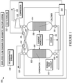
- FIG. 1 illustrates a diagram of an embodiment of a fixed-bed adiabatic calcium looping apparatus 100 of the present teaching.
- FIG. 1 diagrams a simplified flow diagram for adiabatic calcium looping.
- the fixed-bed adiabatic calcium looping apparatus 100 comprises a first pressure vessel 102 and a second pressure vessel 104.
- Each pressure vessel 102, 104 contains the same type of sorbent monolith 106.
- the sorbent may comprises pellets of sorbent material. As described in more detail later in this specification, these sorbents capture and release CO 2 based on operating conditions in the pressure vessels 102, 104.
- the first and second pressure vessels 102, 104 may also include sensors that monitor for saturation of carbon dioxide.
- the first and second pressure vessels 102, 104 may include a heater that controls a temperature of the fixed bed sorbent to a temperature at which it decarbonizes the carbonaceous gases.
- the temperature may also be controlled to a temperature that optimizes decarbonization and/or that optimizes sintering of the fixed bed sorbent.
- Each pressure vessel includes a port with a valve 108, 110 that is connected to a supply of syngas from clean-up 112.
- the syngas may be supplied from a variety of sources.
- the syngas comprises a variety of carbonaceous species, including carbon monoxide, methane, carbon dioxide and hydrogen. Different sources of syngas may comprise different carbonaceous species, and not all species are present in all syngas.
- Steam 114 is also added at this location proximate to the valves 108, 110.
- Each pressure vessel 102, 104 includes a port with a valve 116, 118 connected to a compressor 120.
- Each pressure vessel 102, 104 includes a port with a valve 122, 124 that is connected to an output 126 of the fixed-bed adiabatic calcium looping apparatus 100 that expels decarbonated syngas 128 at the output 126.
- valve 108 and valve 122 are in the open configuration while valve 116 is in the closed configuration on the first pressure vessel 102. This causes high-pressure syngas to enter and pressurize the first pressure vessel 102.
- the first pressure vessel 102 operates as a carbonator.
- Valve 110 and valve 124 are in the closed configuration and valve 118 is in the open configuration on the second pressure vessel 104.
- This valve configuration causes sufficient vacuum from the compressor 120 in the second pressure vessel 104 for calcination, causing a release of carbon dioxide from the second pressure vessel.
- the output of the compressor 120 is connected to an output 130 of the fixed bed adiabatic calcium looping apparatus 100.
- CO 2 to pipeline 132 exits from output 130 of the fixed bed adiabatic calcium looping apparatus 100.
- Valves 108, 110, 116, 118, 122, and 124 are opened and closed appropriately to produce high pressure in the pressure vessel acting as a carbonator, and low pressure in the pressure vessel acting as a calciner.
- the valve configuration cycles as the carbonation and calciner processes cycle.
- the end of each cycle occurs when all of the sorbent in the carbonator nears saturation.
- the switching of the valve configuration causes a pressure swing in the vessels. This is referred to as a pressure swing reaction.
- a controller 134 is connected to valves 108, 110, 116, 118, 122, and 124.
- the controller 134 actuates the valves at the end of each cycle, which causes the pressure vessels 102, 104 to switch from performing calcination to performing carbonation and vice versa.
- the water-gas shift reaction and a carbonation reaction are both performed in a single pressure vessel.
- steam reformation of methane is also performed in the same pressure vessel.
- Catalysts may be included in the fixed bed sorbent. In some embodiments, these reactions are performed simultaneously.
- the controller 134 determines the timing of a cycle by monitoring a peak temperature of the sorbent near its outlet.
- temperatures for the adiabatic calcium looping of the present teaching are typically between 800°C to 950°C. If the minimal temperature is too low, the power needed to compress the CO 2 to pipeline pressures rises disproportionally to the benefits, while at temperatures that are too high, the sorbent sinters, rendering it less reactive.
- the carbonation reaction occurring in one of the vessels reacts the carbonaceous species in the syngas to produce decarbonized syngas.
- the decarbonized syngas comprises hydrogen.
- the carbon dioxide produced by carbonation is captured in the sorbent.
- the syngas contains one or more of the following gases: CO (carbon monoxide), CO 2 , (carbon dioxide) and CH 4 (methane).
- CO carbon monoxide
- CO 2 carbon dioxide
- CH 4 methane
- the CO 2 in syngas is captured directly by calcium looping, while the CO in the syngas must first be converted into CO 2 by the water gas shift reaction, in which the CO reacts with steam to form CO 2 and H 2 .
- the CH 4 can be steam-reformed to produce hydrogen and CO 2 .
- the syngas has a very low concentration of hydrogen sulfide to avoid poisoning the catalyst.
- a Sorbent-Enhanced Reaction works only because the sorbent removes the CO 2 of the shift reaction as soon as it is formed. This creates a very low partial pressure of CO 2 , which, in accordance with the Le Chatelier principal, enables the shift reaction to occur at significantly higher temperatures than in the absence of sorbent.
- both sorbent enhancement and steam methane reforming processes occur. This is referred to by the acronym SM-SER, where the SM refers to steam-methane reforming.
- Steam methane reforming is a process in which methane in a gas is heated using steam as a catalyst to produce hydrogen and carbon dioxide.
- One feature of the present teaching is the processing of both a sorbent-enhanced water-gas shift reaction and a steam methane reforming reaction using the same sorbent in the same vessel, resulting in lower cost and higher carbon capture efficiency than prior art systems.
- the adiabatic calcium looping apparatus 100 uses fixed-bed reactors 102, 104 with valving to alternate the function of each reactor at the end of each cycle. In some embodiments, the end of each cycle occurs when all of the sorbent in the carbonator nears saturation.
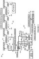
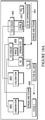
- FIG. 2 illustrates a block diagram of a simplified flow diagram of an embodiment of a polygeneration system 200 of the present teaching.
- Polygeneration refers to a power plant that includes chemical production.
- Coal 202 is input into a coal feed system 204 that feeds a char preparation system 206.
- the char preparation system 206 includes a devolatizer and a pulverizer.
- Char 208 from the char preparation system 206 is provided to a gasifier 210 that is part of an indirect gasifier 212.
- the indirect gasifier 212 also comprises a combustor 214.
- the combustor 214 takes in air 216 and H 2 218 and produces a mixture of N 2 and steam 220.
- the output of the gasifier 210 enters a syngas clean-up system 222 that removes pollutants 224 at an exhaust 226.
- the output of the syngas clean-up 222 is split into two parts at splitter 223 and part of the output is provided to an adiabatic calcium loop CH 4 reformer, CO shift reactor and carbonator reactor 228.
- the adiabatic calcium loop CH 4 reformer, CO shift reactor and carbonator reactor 228 also takes in steam 230 and methane 232.
- a first output 233 of the adiabatic calcium loop CH 4 reformer, CO shift reactor and carbonator reactor 228 supplies H 2 .
- the first output 233 is split three ways at a splitter 235.
- One output of the splitter 235 is connected through a valve 229 to a combined cycle power block 234 that is part of a power block 236.
- the combined cycle power block 234 is also supplied a mixture of N 2 and steam 220 from the combustor 214.
- the power block 236 also comprises a dry flue 238 that supplies gas from the combined cycle power block 234 to a stack.
- the power block 236 generates power 240.
- a second output 242 of the adiabatic calcium loop CH 4 reformer, CO shift reactor and carbonator reactor 228 supplies CO 2 to cooler compressor and pipeline 244.
- One output from splitter 223 supplying clean syngas is connected through valve 246 to a combiner 248.
- the combiner 248 joins an output from the splitter 235 supplying hydrogen that is connected to the combiner 248 through valve 250.
- the output of combiner 248 is connected to a Fischer Tropsch system 252 that is part of a coal-to-liquids reactor 254.
- the coal-to-liquids reactor 254 produces chemicals and fuels 256.
- Methane gas 232 is supplied at an output of the Fischer Tropsch system 252, and provided to an input of the adiabatic calcium loop CH 4 reformer, CO shift reactor and carbonator reactor 228.
- One output of the splitter 235 connected to the adiabatic calcium loop CH 4 reformer, CO shift reactor and carbonator reactor 228 is connected through valve 243 to supply the H 2 218 to the combustor 214.
- the H2 / CO ratio going to the coal-to-liquids reactor 254 is specific to each chemical to be produced. This can readily be adjusted to the required level by controlling the four valves 229, 243, 246, 250 surrounding the outlet of the adiabatic calcium loop CH 4 reformer, CO shift reactor and carbonator reactor 228. Adjusting the CO-H 2 ratio of prior art systems is much more difficult.
- adiabatic calcium looping employs one or more pairs of pressure vessels where one pressure vessel comprises a carbonator and the other pressure vessel comprises a calciner.
- the flow through the carbonator is driven by the high pressure of the syngas conveyed through it.
- the low pressure in the calciner is created by having the calciner's output coupled to a heat exchanger that provides cooling.
- the output of the heat exchanger is coupled to an entrance of the first stage of a compressor, whose inlet is operated at the low pressure required to calcine the sorbent in the calciner.
- the compressor and its subsequent stages serves to compress the carbon dioxide to the pipeline pressure for sequestration.
- the compressor is staged.
- the compressor includes intercoolers, which are provided to increase the compressor efficiency.
- FIG. 3 illustrates an embodiment of an adiabatic calcium looping and CO 2 compression apparatus 300 of the present teaching.
- the adiabatic calcium looping and CO 2 compression apparatus 300 comprises an adiabatic calcium looping reactor portion 302 and a CO 2 compression portion 304.
- the adiabatic calcium looping reactor portion 302 includes a first pressure vessel 306 containing a solid sorbent and a second pressure vessel 308 containing a solid sorbent.
- the first pressure vessel 306 has four ports that are controlled by valves 310, 312, 314, and 316.
- the second pressure vessel 308 has four ports that are controlled by valves 318, 320, 322, and 324.
- Valves 310, 314, and 320 are open and valves 312, 316, 318, 322 and 324 are closed. Valves 310, 318 connect the first and second pressure vessels 306, 308 to a syngas heater 326 that is provided syngas and steam 328 at an input 330. Valves 314, 322 connect the first and second pressure vessels 306, 308 respectively to an output 332 of the adiabatic looping portion 302 that provides decarbonized syngas 334. Valves 312, 320 connect the first and second pressure vessels 306, 308 respectively to heat exchanger 336 via a valve 338. Valves 312, 320, 338 pass CO 2 when open.
- Valves 316, 324 connect the first and second pressure vessels 306, 308 respectively to a gasifier (not shown) and provide contaminated gas to the gasifier when the valves 316, 324 are open.
- the heat exchanger 336 connects the adiabatic calcium looping reactor portion 302 to the CO 2 compression portion 304.
- valves 310, 314, and 320 When the configuration of valves 310, 314, and 320 are open and the configuration of valves 312, 316, 318, 322 and 324 are closed, the first pressure vessel 306 operates as a carbonator, and the second pressure vessel 308 operates as a calciner. That is, closed valves 318, 322, 324 and open valve 320 together with open valve 338 connecting pressure vessel 308 to the compressor results in low pressure in pressure vessel 308 that causes the sorbent to release CO 2 .
- valve 310 When valve 310 is open, valve 312 is closed, valve 316 is closed, and valve 314 is opened connecting pressure vessel 306 to the output 332, both a water shift reaction and adsorption of CO 2 in the sorbent in the pressure vessel 306 produces decarbonized syngas 334.
- syngas and steam 328 enter the adiabatic calcium looping portion 302
- CO 2 340 exits to an input 342 of the CO 2 compression portion 304
- decarbonized syngas 334 exits via output 332.
- looping operation cycles the pressure vessels between carbonator and calciner operation.
- valves 310, 312, 314, 316, 318, 320, 322, and 324 are configured to support the operating conditions in the pressure vessels 306, 308 consistent with a carbonation or calciner process, and to collect and expel the associated products.
- the CO 2 compression portion 304 comprises a series of three heat-exchanger/compression stages 344, 346, and 348.
- the CO 2 compression portion 304 produces low pressure at the pressure vessel 308 configured as a calciner, and produces a high pressure at an output connected to a pipeline 350.
- the pressure at the output connected to a pipeline 350 is approximately 2200 lbs.
- the pressure after heat exchanger 336 is approximately 3 lbs.
- Each heat-exchanger/compression stage includes a heat exchanger 352 and compressor 354.
- the output of the first heat-exchanger/compression stage 344 is connected back to the input 342 through a valve 356.
- This valved loop provides surge suppression during changeover of the pressure vessels 306, 308 from calciner to carbonator roles when valves 310, 314, and 320 are switched off and valves 312, 318 and 322 are switched on.
- the last heat-exchanger/compression stage 348 is connected to a heat exchanger 358 and the output 350 that provides CO 2 to pipeline.
- FIG. 4 illustrates a graph 400 representing a temperature cycle of the sorbent during an embodiment of an adiabatic calcium looping cycle of the present teaching.
- the gases surrounding the sorbent relative to the dissociation line determines whether a carbonation or calcination process proceeds in the solid sorbent.
- the dissociation line is the diagonal line across the chart. Carbonation occurs when the sorbent is in the top-left sector, and calcination occurs in the opposite sector.
- higher partial pressure of the CO 2 in the pressure vessel is consistent with carbonation
- lower partial pressure of the CO 2 in the pressure vessel is consistent with calcination.
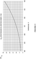
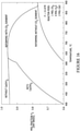
- FIG. 5 illustrates a graph 500 of CO 2 vapor pressures versus temperature for an embodiment of a limestone sorbent of the present teaching.
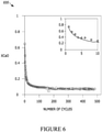
- FIG. 6 illustrates a graph 600 representing the reactivity of plain untreated limestone used in an embodiment of the adiabatic calcium looping method of the present teaching. Sintering reduces the surface area of the pores within the sorbent. If limestone were the only material used to make the sorbent, its reactivity would drop until it reached equilibrium reactivity of only 7%, lower than what is needed.
- FIG. 7 illustrates a graph 700 representing the reactivity of limestone doped with calcium aluminate.
- the calcium oxide is doped with ten percent calcium aluminate. In this embodiment, CaO conversion percent remains around 30% for hundreds of cycles.
- the effects of sintering are also reduced by mixing an appropriate additive to the limestone, such as a calcium aluminate.
- FIG. 8 illustrates a schematic drawing 800 of a particle with selected additives that increase the permeability of sorbent at high temperature. Pores 802 support CO 2 diffusion. Ion diffusion takes place in inner hard sections 804. Pores 802 are surrounded by outward soft sections that support bulk mass transfer.
- the use of an additive, such as calcium aluminate opens passages within the sorbent that counters the effects of sintering by providing additional passages to the pores 802.
- the temperature range of the adiabatic looping cycle of the present teaching is 800-950°C.
- the lower temperature, 800°C is established by the tradeoff of increased capture efficiency of even lower temperatures against the increased power required for the CO 2 compressor that brings the gas to the pipeline pressure at lower temperatures.
- the higher limit, 950°C is established by the tradeoff between using smaller, more economical pressure vessels which use higher temperatures versus the greater frequency with which the sorbent must be restored by either reactivating the sorbent or replacing it that drives using a lower temperature swing.
- a smaller temperature swing would reduce the need to reactivate or replace the sorbent, but requires larger, and thus costlier, reactors, or more frequent cycling of the reactors, which reduces the length of time between overhauls.
- FIG. 9 illustrates a graph 900 representing the reactivity of the sorbent as a function of temperature change of the sorbent during the carbon capture cycle in an embodiment of an adiabatic calcium looping method of the present teaching.
- the portion of the sorbent that has been made inactive by sintering is factored in the 12.6% of the thermal mass of the sorbent that must be chemically active.
- Sorbent produced using an additive such as calcium aluminate can have a reactivity of 35%. Since this is higher than the required 12.6% (see FIG. 9 ), additional inert material must be added. Some of this may be calcium aluminate that both increases the reactivity of the sorbent and strengthens it. Another additive is dolomite, whose calcium constituent remains inactive over the operating temperature range of the cycle of the present teaching, thereby providing additional passages to the pores within the sorbent to retain its reactivity. Additionally, fibers of high-temperature materials, such as silicon carbide or metallic superalloys, may be mixed into the sorbent to further strengthen it.
- the sorbent is affected by thermal stress, particularly from hydration, that is used in some embodiments to reactivate the sorbent.
- thermal stress is used in some embodiments to reactivate the sorbent.
- Another source of stress is the thermal cycling that occurs during operation. The thermal stress may be sufficient to form cracks in the sorbent, which adds to operating costs by requiring replacement when the cracks spread sufficiently to block the flow of gases through the sorbent bed.
- the temperature swing is 150°C.
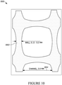
- FIG. 10 illustrates a schematic 1000 of the cross-section of an embodiment of a honeycomb monolith of an adiabatic calcium looping apparatus of the present teaching.
- the honeycomb monolith comprises a wall 1002 of between 0.15 mm and 0.5mm thickness.
- the honeycomb monolith comprises a channel 1004. In some embodiments the channel is 0.9 mm wide.
- each pressure vessel reactor The functions of each pressure vessel reactor are periodically and simultaneously reversed by changing the valve positions at the entrance and exit of each pressure vessel reactor.
- the valve positions are reversed when the sorbent in the carbonator approaches saturation by CO 2 .
- the beds of sorbent are formed in monolithic bricks.
- FIG. 11 illustrates a schematic of an embodiment of a bed 1100 of honeycomb monolith bricks of an adiabatic calcium looping apparatus of the present teaching.
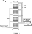
- the honeycombs are stacked into parallel beds, as shown in FIG. 12 .
- the beds are located in sealed sections of a pressure vessel that, together, comprise the carbonator or calciner.
- FIG. 12 illustrates a schematic of an embodiment of an adiabatic calcium looping apparatus 1200 comprising a pressure vessel 1202 containing sorbent beds of honeycomb monolithic 1204 placed in parallel. Multiple chambers of the pressure vessel are connected to one side of the sorbent beds to an input valve manifold, and connected proximate to the other side of the sorbent beds to an output valve manifold 1208.
- the input valve manifold 1206 connects to clean syngas supply
- the output valve manifold 1208 connects to outputs that provide decarbonized syngas and CO 2 .
- Each cell in the pressure vessel 1202 includes a floor plate sealed to the pressure vessel casing, an inlet plenum, a distributor plate, sorbent beds, and an outlet plenum.
- Embodiments that use thin-walled honeycombs have relatively short reaction times. Sorbents below 50- ⁇ thick react in under a second. This is because the reaction is by adsorption and there is molecular interaction between the sorbent and the syngas. Making the honeycombs somewhat thicker than 50- ⁇ thick slows their response time. In some embodiments, the dimensions of a typical honeycomb, are chosen to be thin enough to create reaction times of only a few seconds. A few seconds is more than fast enough to minimize the size and cost of the reactors. Providing passages from the surface to the interior of the sorbent by adding calcium aluminate and dolomite also reduces the reaction time. Lower reaction time advantageously means the pressure vessels can be smaller and lowers costs.
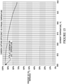
- FIG. 13 illustrates a graph representing the response time for the calcination and carbonation of thin-section sorbent in an embodiment of an adiabatic calcium looping method of the present teaching.
- the speed of both carbonation and calcination depend of the particle's thickness. For particles as thin as 150 microns, the speed of reaction is only a second and the time increases only gradually for particles under 400 microns.
- FIG. 14 illustrates a schematic 1400 of an embodiment of a temperature wave of the sorbent along a flow path of the sorbent bricks.
- the gases upstream of the wave are unreacted, while downstream of the wave they are fully decarbonized.
- the temperature of the sorbent upstream of the wave is at the maximum temperature of the cycle, whereas the sorbent temperature downstream is at the minimum temperature.
- the length of the reaction zone depends on the reactivity of the sorbent. As such, longer reaction times require larger reactors, which are more costly. Therefore, measures are taken to minimize the reaction time. In the worst case, the height of the reaction zone exceeds the height of the bed, in which case "breakthrough" occurs, whereby some of the syngas passes through the carbonator without having its carbonaceous gases removed.
- One feature of the present teaching is that the carbon capture efficiency of the adiabatic calcium looping is very high, over 90%.
- the sorbent is at its upper temperature limit, so the vapor pressure of the CO 2 emitted by the sorbent is also at the highest end of its range. Since calcining is endothermic, the release of the CO 2 cools the sorbent, thereby reducing its pressure until it is fully regenerated at the left end of the calcining operation.
- the calciner is then ready to be switched back into the carbonation mode, whereby the flow through the reactor is pressurized syngas and the cycle begins again.
- FIG. 15 illustrates a graph representing a comparison of the partial pressure of the CO 2 in the syngas to sorbent internal pressure over a cycle.
- FIG. 15 shows that the carbon capture efficiency for some embodiments is 97% when the gasifier pressure for the system operates at 450 psia and the calciner's lowest temperature is 800°C.
- the temperature of the sorbent is controlled by the carbonation and calcination reactions, as the reactions occur within the sorbent, itself.
- the syngas temperature depends on the inlet temperature of the gas along with how much it is heated in the carbonator by the shift reaction. This is as much as 640°F in the absence of methane and less if methane is also being reformed, as reforming is endothermic. These reactions occur only in the gaseous phases, which are steam plus CO, or steam plus methane. Consequently, with the exception of some heat transfer from the gases to the monoliths, the reactions affect principally the gas temperatures.
- Methane contained in the syngas which is enhanced by low temperatures and/or high pressures in the gasifier, or emitted from a Coal-to-X reactor (CTX), where X is any material that coal to be changed into, might produce an unacceptable level of CO 2 emissions when burned in the gas turbine unless they are first steam-reformed into hydrogen and CO. The CO is then shift-reacted with steam to form hydrogen and CO 2 , which is then carbonated by the sorbent.
- CX Coal-to-X reactor
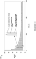
- FIG. 16 illustrates a graph representing steam methane reforming with sorbent-enhanced reaction in an embodiment of an adiabatic calcium looping method of the present teaching.
- One feature of the present teaching is that the processing of a water-gas shift reaction, carbonation reaction, and optionally steam methane reforming occurs in the same pressure vessel as the primary reactions for high-efficiency carbon capture.
- CO 2 flow is controlled during calcination using a valve in the outlet of the calciner that maintains the volumetric flow rate at a constant.
- a second valve in the conduit is used to avoid stalling the compressor during the changeover of pressure vessels, when the flow of CO 2 from the calciner is temporarily interrupted. See, for example, valve 356 in FIG. 3 .
- Flow from the sorbent is proportional to the pressure difference between the interior of the sorbent and the pressure in the flow passages of the honeycombs. If the volumetric flow rate to the compressor is to be kept nearly constant during calcination, the pressure in the calciner will trace the decomposition pressure line (see FIGS. 4 and 5 ) from just under 28 psia at the start of calcination to 2.5 psia at the end. In some embodiments, the compressor power varies over the regeneration cycle, and is 30% lower than if the compressor inlet were always at the minimal pressure at the end of the cycle.
- Changeover describes the conditions when the functions of the reactors are reversed.
- One problem that must be solved is the continuous flow of fuel to the gas turbine.
- Another problem to be avoided is the contamination of the gas in each reactor. CO 2 from the calciner that contaminates the hydrogen sent to the gas turbine would interrupt combustion, while hydrogen from the carbonator containing CO 2 would interfere with the transmission of the CO 2 in the pipeline.
- FIG. 17A illustrates a schematic of a simplified flow diagram 1700 during reactor normal operation at the end of calcination in an embodiment of an adiabatic calcium looping apparatus of the present teaching.
- An accumulator 1702 is placed between a compressor 1704 and the output 1706 that supplies bleed flow to a gasifier.
- a pressure vessel 1708 valved output manifold 1710 connects to the compressor 1704.
- the pressure vessel 1708 includes a sorbent bed 1712.
- FIG. 17B illustrates a schematic of a simplified flow diagram 1700' during reactor normal operation at the end of carbonization in an embodiment of an adiabatic calcium looping apparatus of the present teaching.
- the elements of the apparatus are the same in the embodiment of FIG. 17B as the embodiment of FIG. 17A .
- the valve control on the valved output manifold is different reflecting the particular cycle.
- the beds of the reactors may be switched individually by valving each section of the pressure vessel independently.
- the beds may all be changed in unison if sufficiently large accumulators are used to capture the contaminated gases.
- the flows from the accumulators are then recycled into the outlets of the carbonator and calciner, respectively, over the course of the next cycle.
- FIG. 18A and 18B illustrate schematics of a simplified flow diagram during changeovers in an embodiment of an adiabatic calcium looping apparatus with a heat recovery steam generator (HRSG) of the present teaching.
- FIG. 18A illustrates a pair of pressure vessels with a first pressure vessel 1802 performing a carbonation process and a second pressure vessel 1804 performing a calciner process.
- the first pressure vessel 1802 is receiving syngas and steam 1806 from a HRSG 1808.
- the first pressure vessel 1802 is providing H 2 to the HSRG 1808.
- the second pressure vessel 1804 is providing CO 2 via a CO 2 cooler 1810 and HRSG 1812 to compressors (not shown).
- the syngas and steam 1806 entering the first pressure vessel 1802 is processed through the HRSG 1808 from the input 1814.
- the H 2 provided by the first pressure vessel 1802 passes through the HRSG 1808 before being used for a variety of downstream purposes.
- FIG. 18B illustrates the same pair of pressure vessels of FIG. 18A .
- the first pressure vessel 1802 is performing a calcination process and the second pressure vessel 1804 is performing a carbonation process.
- the first pressure vessel 1802 is providing CO 2 via a CO 2 cooler 1810 and HRSG 1812 to compressors (not shown).
- the second pressure vessel 1804 is receiving syngas and steam 1806 from a HRSG 1808.
- the second pressure vessel 1804 is providing H 2 to the HSRG 1808.
- the syngas and steam 1806 entering the second pressure vessel 1804 is processed through the HRSG 1808.
- the H 2 provided by the second pressure vessel 1804 passes through the HRSG 1808 before being used for a variety of downstream purposes.
- Input and output valve manifolds (not shown) connected to the pair of pressure vessels 1802, 1804, are configured by the valve controller to configure valves (not shown) that control the connections between the pressure vessels 1802, 1804 and HRSG 1808, CO 2 cooler 1810, and HRSG 1812 to support the flow diagrams for the two cycles of operation illustrated in FIGS. 18A and 18B .
- FIGS. 18A and 18B show that the heat recovery system can be used for each cycle. Additional HRSGs can be used to control potential over heating of the syngas in the carbonator.
Landscapes
- Chemical & Material Sciences (AREA)
- Engineering & Computer Science (AREA)
- Chemical Kinetics & Catalysis (AREA)
- Organic Chemistry (AREA)
- Health & Medical Sciences (AREA)
- Analytical Chemistry (AREA)
- General Chemical & Material Sciences (AREA)
- Oil, Petroleum & Natural Gas (AREA)
- Environmental & Geological Engineering (AREA)
- Inorganic Chemistry (AREA)
- Combustion & Propulsion (AREA)
- Biomedical Technology (AREA)
- General Health & Medical Sciences (AREA)
- Separation Of Gases By Adsorption (AREA)
- Gas Separation By Absorption (AREA)
- Solid-Sorbent Or Filter-Aiding Compositions (AREA)
Claims (11)
- System (100, 222, 300, 1200) zur Entkarbonisierung von Gasen unter Verwendung von adiabatischer Calciumschleife, Druckwechsel und einem Paar von alternierenden, druckbeaufschlagten Festbettreaktoren (102, 104, 306, 308), wobei das System Folgendes umfasst:a) einen Eingangsgasverteiler (1206), der eine Vielzahl von Ventilen (108, 110) umfasst und mindestens einen Eingang aufweist, der Synthesegas (112, 328, 1806) und Dampf (114, 328, 1806) empfängt;b) ein Paar Druckbehälter, das einen ersten und einen zweiten Druckbehälter (102, 104, 306, 308, 1202, 1708, 1708', 1802, 1804) umfasst, wobei jeder der ersten und zweiten Druckbehälter Folgendes umfasst:i. ein Festbett aus Sorptionsmittel (106, 1100, 1204, 1712);ii. einen Eingang, der mit einem Ausgang des Eingangsgasverteilers (1206) gekoppelt ist; undiii. einen Ausgang;c) einen Ausgangsgasverteiler (1208), der eine Vielzahl von Ventilen (122, 124) umfasst und einen ersten Eingang aufweist, der mit dem Ausgang des ersten Druckbehälters (102, 306, 1202, 1708, 1802) gekoppelt ist, und einen zweiten Eingang, der mit dem Ausgang des zweiten Druckbehälters (104, 308, 1804) gekoppelt ist;d) eine Ventilsteuerung (134), die mindestens einen Ausgang, der mit dem Eingangsgasverteiler (1206) gekoppelt ist, und mindestens einen Ausgang, der mit dem Ausgangsgasverteiler (1208) gekoppelt ist, aufweist; unde) einen Kompressor (120, 304, 1704), der einen Eingangsanschluss umfasst, der mit einem Anschluss des Ausgangsgasverteilers gekoppelt ist, wobei der Kompressor so eingerichtet ist, dass er dem Ausgangsgasverteiler ausreichend Vakuum bereitstellt, sodass, wenn der erste oder zweite Druckbehälter CO2 ausstößt, dessen Partialdruck unterhalb einer Zersetzungslinie für Calciumcarbonat liegt;dadurch gekennzeichnet, dass:das Festbett aus Sorptionsmittel (106, 1100, 1204, 1712) einen Kalk-, Kalkstein-Wabenmonolithen (1000) umfasst, der Calciumaluminat und Dolomit als Additive umfasst, welche die Reaktionszeit durch Erhöhung der Durchlässigkeit des Festbettsorptionsmittels bei hoher Temperatur verkürzen;das Paar Druckbehälter (102, 104, 306, 308, 1202, 1708, 1708', 1802, 1804) einen Sensor umfasst, der so eingerichtet ist, dass er die Sättigung von Kohlendioxid überwacht.
- System (100, 222, 300, 1200) zur Entkarbonisierung von Gasen nach Anspruch 1, wobei das Festbett aus Sorptionsmittel (106, 1100, 1204, 1712) in jedem des ersten und zweiten Druckbehälters eine sorptionsverstärkte Wasser-Gas-Verschiebungsreaktion verarbeitet, und wobei das Festbett aus Sorptionsmittel in jedem des ersten und zweiten Druckbehälters bevorzugt Dampf-Methan-Reformierung verarbeitet.
- System (100, 222, 300, 1200) zur Entkarbonisierung von Gasen nach Anspruch 1, wobei der mindestens eine Eingang des Eingangsgasverteilers (1206) mit einem Ausgang eines Synthesegasreinigungssystems gekoppelt ist.
- System (100, 222, 300, 1200) zur Entkarbonisierung von Gasen nach Anspruch 1, das weiter einen Wärmerückgewinnungs-Dampferzeuger umfasst, der einen Ausgang aufweist, der mit dem Eingang des Kompressors (120, 304, 1704) gekoppelt ist.
- System (100, 222, 300, 1200) zur Entkarbonisierung von Gasen nach Anspruch 1, wobei der erste und zweite Druckbehälter (102, 104, 306, 308, 1202, 1708, 1708', 1802, 1804) weiter einen Erhitzer (326) umfassen, der eine Temperatur des Festbetts aus Sorptionsmittel (106, 1100, 1204, 1712) in dem ersten und zweiten Druckbehälter auf eine Temperatur steuert, bei der es die kohlenstoffhaltigen Gase entkarbonisiert; und wobei der Erhitzer bevorzugt die Temperatur des Festbetts aus Sorptionsmittel in dem ersten und zweiten Druckbehälter auf eine Temperatur steuert, welche die Entkarbonisierung und/oder Sinterung des Festbettsorptionsmittels optimiert.
- Verfahren zur Entkarbonisierung von Gasen unter Verwendung einer adiabatischen Calciumschleife und eines Druckwechsels in einem ersten und einem zweiten Druckbehälter (102, 104, 306, 308, 1202, 1708, 1708' 1802, 1804), die jeweils ein Festbettsorptionsmittel (106, 1100, 1204, 1712) umfassen, das einen Kalk-, Kalkstein-Wabenmonolithen (1000) umfasst, wobei das Verfahren Folgendes umfasst:a) Bereitstellen eines Festbettsorptionsmittels (106, 1100, 1204, 1712) in jedem des ersten und zweiten Druckbehälters (102, 104, 306, 308, 1202, 1708, 1708', 1802, 1804);b) Erhöhen der Durchlässigkeit des Festbettsorptionsmittels (106, 1100, 1204, 1712) bei hoher Temperatur durch Bereitstellen von Calziumaluminat und Dolomit in dem Sorptionsmittel, wobei das Calziumaluminat und der Dolomit Durchgänge zu einem Inneren des Festbettsorptionsmittels (106, 1100, 1204, 1712) bereitstellen;c) Empfangen von Synthesegas (112, 328, 1806) und Dampf (114, 328, 1806) in dem ersten Druckbehälter (102, 306, 1202, 1708, 1802);d) Durchführen einer Karbonisierungs- und Wasser-Gas-Verschiebungsreaktion in dem erstenDruckbehälter (102, 306, 1202, 1708, 1802), bei der kohlenstoffhaltige Spezies in dem empfangenen Synthesegas mit dem empfangenen Dampf reagieren, um Kohlendioxid zu erzeugen.e) Abführen von entkarbonisiertem Synthesegas aus dem ersten Druckbehälter (102, 306, 1202, 1708, 1802);f) Durchführen einer Kalzinierungsreaktion in dem zweiten Druckbehälter (104, 308, 1202, 1708, 1804) zur Freisetzung von Kohlendioxid;g) Bereitstellen eines Vakuums für den zweiten Druckbehälter, das veranlasst, dass Kohlendioxid aus dem zweiten Druckbehälter bei einem Druck austritt, der unterhalb einer Zersetzungsdrucklinie liegt; undh) Durchführen von Druckwechsel von Reaktionen in dem ersten und zweiten Druckbehälter (102, 104, 306, 308, 1202, 1708, 1708', 1802, 1804), wenn sich im Wesentlichen das gesamte Festbettsorptionsmittel im ersten Druckbehälter der Sättigung nähert, unter Verwendung einer Ventilsteuerung und eines Sensors zur Überwachung der Sättigung von Kohlendioxid.
- Verfahren nach Anspruch 6, wobei die Karbonisierungsreaktion in dem ersten Druckbehälter (102, 306, 1202, 1708, 1802) weiter die Durchführung einer Dampf-Methan-Reformierungsreaktion in dem ersten Druckbehälter (102, 306, 1202, 1708, 1802) umfasst.
- Verfahren nach Anspruch 6, weiter umfassend:a) Empfangen von Synthesegas und Dampf in dem zweiten Druckbehälter (104, 308, 1202, 1708, 1804);b) Durchführen einer Karbonisierungs- und Wasser-Gas-Verschiebungsreaktion in dem zweiten Druckbehälter (104, 308, 1202, 1708, 1804), bei der kohlenstoffhaltige Spezies in dem empfangenen Synthesegas mit dem empfangenen Dampf reagieren, um Kohlendioxid zu erzeugen;c) Abführen von entkarbonisiertem Synthesegas aus dem zweiten Druckbehälter (104, 308, 1202, 1708, 1804);d) Durchführen einer Kalzinierungsreaktion in dem ersten Druckbehälter (102, 306, 1202, 1708, 1802) zur Erzeugung von Kohlendioxid; unde) Bereitstellen eines Vakuums für den ersten Druckbehälter (102, 306, 1202, 1708, 1802), das veranlasst, dass Kohlendioxid aus dem ersten Druckbehälter (102, 306, 1202, 1708, 1802) bei einem Druck austritt, der unterhalb einer Zersetzungsdrucklinie liegt.
- Verfahren nach Anspruch 8, wobei die Karbonisierungsreaktion in dem zweiten Druckbehälter (104, 308, 1202, 1708, 1804) weiter die Durchführung einer Dampf-Methan-Reformierungsreaktion in dem zweiten Druckbehälter (104, 308, 1202, 1708, 1804) umfasst.
- Verfahren nach Anspruch 6, wobei das Empfangen von Synthesegas das Empfangen von Synthesegas aus einem Synthesegasreinigungssystem umfasst, das Schadstoffe entfernt.
- Verfahren nach Anspruch 6, wobei die kohlenstoffhaltige Spezies Folgendes umfasst: Kohlenmonoxid; Kohlendioxid; Methan; oder Kohlenmonoxid und Methan.
Applications Claiming Priority (2)
| Application Number | Priority Date | Filing Date | Title |
|---|---|---|---|
| US201562237709P | 2015-10-06 | 2015-10-06 | |
| PCT/US2016/055602 WO2017062526A1 (en) | 2015-10-06 | 2016-10-05 | Method and apparatus for adiabatic calcium looping |
Publications (3)
| Publication Number | Publication Date |
|---|---|
| EP3359628A1 EP3359628A1 (de) | 2018-08-15 |
| EP3359628A4 EP3359628A4 (de) | 2019-05-22 |
| EP3359628B1 true EP3359628B1 (de) | 2022-03-02 |
Family
ID=58447463
Family Applications (1)
| Application Number | Title | Priority Date | Filing Date |
|---|---|---|---|
| EP16854265.2A Not-in-force EP3359628B1 (de) | 2015-10-06 | 2016-10-05 | Verfahren und vorrichtung für adiabatischen calciumschleife |
Country Status (4)
| Country | Link |
|---|---|
| US (2) | US11084721B2 (de) |
| EP (1) | EP3359628B1 (de) |
| CN (1) | CN108138060B (de) |
| WO (1) | WO2017062526A1 (de) |
Families Citing this family (13)
| Publication number | Priority date | Publication date | Assignee | Title |
|---|---|---|---|---|
| CN106964244A (zh) * | 2017-04-17 | 2017-07-21 | 武汉理工大学 | 加压氧化钙捕集二氧化碳的装置及方法 |
| GB2569366B (en) * | 2017-12-15 | 2022-06-01 | Fjell Biodry As | Gas-solid reactor |
| CN108619896B (zh) * | 2018-05-16 | 2023-11-21 | 安徽建筑大学 | 一种基于切换式填充床反应器的co2循环脱除装置及方法 |
| EP4065668A4 (de) | 2019-11-25 | 2023-12-27 | Wormser Energy Solutions, Inc. | Holzkohleaufbereitungssystem und vergaser für die volldampfvergasung mit kohlenstoffabscheidung |
| CN111821855B (zh) * | 2020-07-17 | 2021-05-14 | 空哲环境工程(上海)有限公司 | 化学催化模组 |
| CN113509834B (zh) * | 2021-04-08 | 2023-02-14 | 华南理工大学 | 局部钙循环与纯氧燃烧耦合的水泥生产碳捕集装置及工艺 |
| EP4098613A1 (de) | 2021-06-03 | 2022-12-07 | Consejo Superior de Investigaciones Cientificas | Vakuumwechselkalzinierverfahren zur herstellung von hochreinem co2 aus caco3 |
| US11471832B1 (en) * | 2021-08-03 | 2022-10-18 | Hamilton Sundstrand Corporation | Solid amine combined carbon dioxide separation process |
| CN113648826B (zh) * | 2021-08-20 | 2022-08-26 | 山东大学 | 一种基于钙循环的协同脱除co2和no的方法 |
| CN114017153B (zh) * | 2021-12-09 | 2025-01-24 | 中国华能集团清洁能源技术研究院有限公司 | 一种基于固体吸收剂的双循环igcc发电系统和方法 |
| EP4371649A1 (de) | 2022-11-18 | 2024-05-22 | Consejo Superior De Investigaciones Científicas (CSIC) | Dampfpartialdruckwechselkalzinierungsverfahren zur herstellung von hochreinem co2 aus caco3 |
| ES3037545T3 (en) * | 2022-12-01 | 2025-10-02 | Consejo Superior Investigacion | Method of hydrogenation and calcination of caco3 with h2 |
| WO2025063253A1 (ja) * | 2023-09-19 | 2025-03-27 | 住友重機械工業株式会社 | 二酸化炭素回収装置及び二酸化炭素回収方法 |
Family Cites Families (43)
| Publication number | Priority date | Publication date | Assignee | Title |
|---|---|---|---|---|
| US3373562A (en) | 1966-03-17 | 1968-03-19 | Wingaersheek Turbine Co Inc | Combustion chamber for gas turbines and the like having improved flame holder |
| US4013395A (en) | 1971-05-11 | 1977-03-22 | Wingaersheek, Inc. | Aerodynamic fuel combustor |
| US4051791A (en) | 1975-08-15 | 1977-10-04 | Wormser Engineering, Inc. | Coal burning arrangement |
| US4003691A (en) | 1975-08-22 | 1977-01-18 | Consolidated Natural Gas Service Co., Inc. | Recirculating burner |
| US4149559A (en) | 1976-05-21 | 1979-04-17 | Wingaersheek, Inc. | Pressure regulator |
| US4135885A (en) | 1977-01-03 | 1979-01-23 | Wormser Engineering, Inc. | Burning and desulfurizing coal |
| US4303023A (en) | 1979-11-08 | 1981-12-01 | Wormser Engineering, Inc. | Fluidized bed fuel burning |
| US4279205A (en) | 1979-09-24 | 1981-07-21 | Wormser Engineering, Inc. | Storage |
| US4279207A (en) | 1979-04-20 | 1981-07-21 | Wormser Engineering, Inc. | Fluid bed combustion |
| JPS5749719A (en) * | 1980-09-10 | 1982-03-23 | Matsushita Electric Ind Co Ltd | Combustion apparatus |
| DE3268510D1 (en) | 1981-06-05 | 1986-02-27 | Exxon Research Engineering Co | An integrated catalytic coal devolatilisation and steam gasification process |
| US4499857A (en) | 1983-10-17 | 1985-02-19 | Wormser Engineering, Inc. | Fluidized bed fuel burning |
| JPS6099017A (ja) * | 1983-10-31 | 1985-06-01 | Kanai Jiyuuyou Kogyo Kk | 紡機用メタリツクワイヤ |
| US4578175A (en) | 1984-04-02 | 1986-03-25 | Conoco Inc. | Combined process for coal pyrolysis and char gasification |
| US5122346A (en) | 1990-05-10 | 1992-06-16 | Alex Wormser | Distributor for multistage fluidized beds |
| US5997220A (en) | 1994-12-14 | 1999-12-07 | Wormser Systems, Inc. | Vertical-shaft airlock |
| US5655853A (en) | 1994-12-14 | 1997-08-12 | Wormser Systems, Inc. | Vertical-shaft airlock |
| US6290921B1 (en) * | 1999-11-03 | 2001-09-18 | Foster Wheeler Enegeria Oy | Method and apparatus for binding pollutants in flue gas |
| DE10016825A1 (de) * | 2000-04-07 | 2001-10-11 | Merck Patent Gmbh | Monolithische Sorbentien mit faserverstärkter Kunststoffummantelung |
| WO2002051966A1 (en) | 2000-12-26 | 2002-07-04 | Ebara Corporation | Fluidized-bed gasification method and apparatus |
| RU2287067C2 (ru) | 2002-09-17 | 2006-11-10 | Фостер Уилер Энерджи Корпорейшн | Система с гибридным циклом газификации угля с использованием рециркулирующей рабочей текучей среды и способ генерирования электроэнергии |
| EP1608445B1 (de) * | 2003-04-03 | 2013-07-03 | Fluor Corporation | Konfigurationen und verfahren zur kohlenstoffgewinnung |
| US7083658B2 (en) * | 2003-05-29 | 2006-08-01 | Alstom Technology Ltd | Hot solids gasifier with CO2 removal and hydrogen production |
| FR2857696B1 (fr) * | 2003-07-18 | 2005-10-21 | Saint Gobain Ct Recherches | Bloc filtrant pour la filtration de particules contenues dans les gaz d'echappement d'un moteur a combustion interne. |
| US7820591B2 (en) * | 2005-01-04 | 2010-10-26 | Korea Electric Power Corporation | Highly attrition resistant and dry regenerable sorbents for carbon dioxide capture |
| EP1951411B1 (de) * | 2005-10-21 | 2018-03-28 | Calix Pty Ltd. | System und verfahren zur verarbeitung mittels calcinierungs-/carbonatisierungszyklen |
| CN101005139A (zh) * | 2006-01-16 | 2007-07-25 | 逢甲大学 | 多孔性碳电极基材及其制法 |
| US7722705B2 (en) * | 2006-05-11 | 2010-05-25 | Corning Incorporated | Activated carbon honeycomb catalyst beds and methods for the use thereof |
| CN102112205B (zh) * | 2008-05-15 | 2014-09-17 | Calix有限公司 | 用于处理烟道气的系统和方法 |
| WO2010014938A2 (en) | 2008-07-31 | 2010-02-04 | Alstom Technology Ltd. | System for hot solids combustion and gasification |
| EP2352698A4 (de) * | 2008-10-13 | 2012-06-06 | Univ Ohio State Res Found | Calcium-looping-verfahren für die herstellung von hochreinem wasserstoff mit abscheidung von kohlenstoffdioxid, schwefel und haliden |
| CN101618292A (zh) | 2008-11-10 | 2010-01-06 | 李元胜 | 一种对工业三废进行综合利用的系统 |
| EP2415509B1 (de) * | 2009-03-31 | 2015-07-22 | NGK Insulators, Ltd. | Wabenfilter und verfahren zu seiner herstellung |
| US20120164032A1 (en) * | 2009-09-18 | 2012-06-28 | Wormser Energy Solutions, Inc. | Systems, devices and methods for calcium looping |
| US9873840B2 (en) | 2009-09-18 | 2018-01-23 | Wormser Energy Solutions, Inc. | Integrated gasification combined cycle plant with char preparation system |
| CA2778179C (en) | 2009-10-24 | 2017-07-25 | Calix Limited | System and method for processing an input fuel gas and steam to produce carbon dioxide and an output fuel gas |
| JP5578907B2 (ja) | 2010-03-29 | 2014-08-27 | 三菱重工業株式会社 | 石炭ガス化複合発電プラント |
| US8945496B2 (en) * | 2010-11-30 | 2015-02-03 | General Electric Company | Carbon capture systems and methods with selective sulfur removal |
| SG194538A1 (en) * | 2011-04-18 | 2013-12-30 | Ryncosmos Llc | Method and apparatus for removal of carbon dioxide from automobile, household and industrial exhaust gases |
| CN104169396B (zh) | 2011-11-04 | 2016-08-24 | 国际热化学恢复股份有限公司 | 用于原料向油和气的弹性转化的系统和方法 |
| US9540999B2 (en) | 2012-01-17 | 2017-01-10 | Peregrine Turbine Technologies, Llc | System and method for generating power using a supercritical fluid |
| PL2808073T3 (pl) | 2013-05-31 | 2021-03-08 | Consejo Superior De Investigaciones Cientificas (Csic) | UKŁAD WYCHWYTYWANIA CO<sub>2</sub> Z GAZÓW SPALINOWYCH ZA POMOCĄ PĘTLI CHEMICZNEJ CAO/CACO3 |
| CN110168058B (zh) | 2016-09-13 | 2022-01-25 | 八河流资产有限责任公司 | 利用部分氧化的动力生产系统和方法 |
-
2016
- 2016-10-05 WO PCT/US2016/055602 patent/WO2017062526A1/en not_active Ceased
- 2016-10-05 EP EP16854265.2A patent/EP3359628B1/de not_active Not-in-force
- 2016-10-05 US US15/286,514 patent/US11084721B2/en not_active Expired - Fee Related
- 2016-10-05 CN CN201680058328.6A patent/CN108138060B/zh not_active Expired - Fee Related
-
2021
- 2021-07-22 US US17/382,650 patent/US20210347638A1/en not_active Abandoned
Also Published As
| Publication number | Publication date |
|---|---|
| CN108138060B (zh) | 2021-09-07 |
| US20170096335A1 (en) | 2017-04-06 |
| US11084721B2 (en) | 2021-08-10 |
| EP3359628A1 (de) | 2018-08-15 |
| CN108138060A (zh) | 2018-06-08 |
| WO2017062526A1 (en) | 2017-04-13 |
| EP3359628A4 (de) | 2019-05-22 |
| US20210347638A1 (en) | 2021-11-11 |
Similar Documents
| Publication | Publication Date | Title |
|---|---|---|
| EP3359628B1 (de) | Verfahren und vorrichtung für adiabatischen calciumschleife | |
| CN1795257B (zh) | 能移走co2并产生h2的热固体气化器 | |
| AU772704B2 (en) | Hydrogen production from carbonaceous material | |
| CA2479886C (en) | Combustion method with integrated carbon dioxide separation by means of carbonation | |
| CN102665871B (zh) | 用于处理输入燃料气体和蒸汽以制造二氧化碳和输出燃料气体的系统和方法 | |
| US20140158939A1 (en) | Calcium looping process for high purity hydrogen production integrated with capture of carbon dioxide, sulfur and halides | |
| US20120164032A1 (en) | Systems, devices and methods for calcium looping | |
| WO2019073867A1 (ja) | メタン製造システム | |
| Harrison | Calcium enhanced hydrogen production with CO2 capture | |
| Calabrò et al. | Possible optimal configurations for the ZECOMIX high efficiency zero emission hydrogen and power plant | |
| EP2478074A1 (de) | Calcium-looping-systeme, -vorrichtungen und -verfahren | |
| Manzolini et al. | Sorption‐Enhanced Fuel Conversion | |
| Lisbona et al. | Energy Integration of Processes for Solid Looping CO2 Capture Systems | |
| CN119896962A (zh) | 二氧化碳捕集利用方法及其装置和应用 | |
| Romano et al. | CO2 Capture from Industrial Sources by High-temperature Sorbents | |
| Li et al. | Enhanced hydrogen production from circulating fluidized bed biomass gasification by double equilibrium shift |
Legal Events
| Date | Code | Title | Description |
|---|---|---|---|
| STAA | Information on the status of an ep patent application or granted ep patent |
Free format text: STATUS: THE INTERNATIONAL PUBLICATION HAS BEEN MADE |
|
| PUAI | Public reference made under article 153(3) epc to a published international application that has entered the european phase |
Free format text: ORIGINAL CODE: 0009012 |
|
| STAA | Information on the status of an ep patent application or granted ep patent |
Free format text: STATUS: REQUEST FOR EXAMINATION WAS MADE |
|
| 17P | Request for examination filed |
Effective date: 20180327 |
|
| AK | Designated contracting states |
Kind code of ref document: A1 Designated state(s): AL AT BE BG CH CY CZ DE DK EE ES FI FR GB GR HR HU IE IS IT LI LT LU LV MC MK MT NL NO PL PT RO RS SE SI SK SM TR |
|
| AX | Request for extension of the european patent |
Extension state: BA ME |
|
| DAV | Request for validation of the european patent (deleted) | ||
| DAX | Request for extension of the european patent (deleted) | ||
| A4 | Supplementary search report drawn up and despatched |
Effective date: 20190425 |
|
| RIC1 | Information provided on ipc code assigned before grant |
Ipc: C10K 1/00 20060101AFI20190417BHEP Ipc: C01B 3/34 20060101ALI20190417BHEP Ipc: B01D 53/62 20060101ALI20190417BHEP Ipc: B01D 53/82 20060101ALI20190417BHEP Ipc: C10J 3/48 20060101ALI20190417BHEP |
|
| RAP1 | Party data changed (applicant data changed or rights of an application transferred) |
Owner name: WORMSER ENERGY SOLUTIONS, INC. |
|
| GRAP | Despatch of communication of intention to grant a patent |
Free format text: ORIGINAL CODE: EPIDOSNIGR1 |
|
| STAA | Information on the status of an ep patent application or granted ep patent |
Free format text: STATUS: GRANT OF PATENT IS INTENDED |
|
| INTG | Intention to grant announced |
Effective date: 20210401 |
|
| GRAJ | Information related to disapproval of communication of intention to grant by the applicant or resumption of examination proceedings by the epo deleted |
Free format text: ORIGINAL CODE: EPIDOSDIGR1 |
|
| STAA | Information on the status of an ep patent application or granted ep patent |
Free format text: STATUS: REQUEST FOR EXAMINATION WAS MADE |
|
| INTC | Intention to grant announced (deleted) | ||
| GRAP | Despatch of communication of intention to grant a patent |
Free format text: ORIGINAL CODE: EPIDOSNIGR1 |
|
| STAA | Information on the status of an ep patent application or granted ep patent |
Free format text: STATUS: GRANT OF PATENT IS INTENDED |
|
| INTG | Intention to grant announced |
Effective date: 20210920 |
|
| GRAS | Grant fee paid |
Free format text: ORIGINAL CODE: EPIDOSNIGR3 |
|
| GRAA | (expected) grant |
Free format text: ORIGINAL CODE: 0009210 |
|
| STAA | Information on the status of an ep patent application or granted ep patent |
Free format text: STATUS: THE PATENT HAS BEEN GRANTED |
|
| AK | Designated contracting states |
Kind code of ref document: B1 Designated state(s): AL AT BE BG CH CY CZ DE DK EE ES FI FR GB GR HR HU IE IS IT LI LT LU LV MC MK MT NL NO PL PT RO RS SE SI SK SM TR |
|
| REG | Reference to a national code |
Ref country code: GB Ref legal event code: FG4D |
|
| REG | Reference to a national code |
Ref country code: CH Ref legal event code: EP Ref country code: AT Ref legal event code: REF Ref document number: 1472242 Country of ref document: AT Kind code of ref document: T Effective date: 20220315 |
|
| REG | Reference to a national code |
Ref country code: DE Ref legal event code: R096 Ref document number: 602016069693 Country of ref document: DE |
|
| REG | Reference to a national code |
Ref country code: IE Ref legal event code: FG4D |
|
| REG | Reference to a national code |
Ref country code: LT Ref legal event code: MG9D |
|
| REG | Reference to a national code |
Ref country code: NL Ref legal event code: MP Effective date: 20220302 |
|
| PG25 | Lapsed in a contracting state [announced via postgrant information from national office to epo] |
Ref country code: SE Free format text: LAPSE BECAUSE OF FAILURE TO SUBMIT A TRANSLATION OF THE DESCRIPTION OR TO PAY THE FEE WITHIN THE PRESCRIBED TIME-LIMIT Effective date: 20220302 Ref country code: RS Free format text: LAPSE BECAUSE OF FAILURE TO SUBMIT A TRANSLATION OF THE DESCRIPTION OR TO PAY THE FEE WITHIN THE PRESCRIBED TIME-LIMIT Effective date: 20220302 Ref country code: NO Free format text: LAPSE BECAUSE OF FAILURE TO SUBMIT A TRANSLATION OF THE DESCRIPTION OR TO PAY THE FEE WITHIN THE PRESCRIBED TIME-LIMIT Effective date: 20220602 Ref country code: LT Free format text: LAPSE BECAUSE OF FAILURE TO SUBMIT A TRANSLATION OF THE DESCRIPTION OR TO PAY THE FEE WITHIN THE PRESCRIBED TIME-LIMIT Effective date: 20220302 Ref country code: HR Free format text: LAPSE BECAUSE OF FAILURE TO SUBMIT A TRANSLATION OF THE DESCRIPTION OR TO PAY THE FEE WITHIN THE PRESCRIBED TIME-LIMIT Effective date: 20220302 Ref country code: ES Free format text: LAPSE BECAUSE OF FAILURE TO SUBMIT A TRANSLATION OF THE DESCRIPTION OR TO PAY THE FEE WITHIN THE PRESCRIBED TIME-LIMIT Effective date: 20220302 Ref country code: BG Free format text: LAPSE BECAUSE OF FAILURE TO SUBMIT A TRANSLATION OF THE DESCRIPTION OR TO PAY THE FEE WITHIN THE PRESCRIBED TIME-LIMIT Effective date: 20220602 |
|
| REG | Reference to a national code |
Ref country code: AT Ref legal event code: MK05 Ref document number: 1472242 Country of ref document: AT Kind code of ref document: T Effective date: 20220302 |
|
| PG25 | Lapsed in a contracting state [announced via postgrant information from national office to epo] |
Ref country code: PL Free format text: LAPSE BECAUSE OF FAILURE TO SUBMIT A TRANSLATION OF THE DESCRIPTION OR TO PAY THE FEE WITHIN THE PRESCRIBED TIME-LIMIT Effective date: 20220302 Ref country code: LV Free format text: LAPSE BECAUSE OF FAILURE TO SUBMIT A TRANSLATION OF THE DESCRIPTION OR TO PAY THE FEE WITHIN THE PRESCRIBED TIME-LIMIT Effective date: 20220302 Ref country code: GR Free format text: LAPSE BECAUSE OF FAILURE TO SUBMIT A TRANSLATION OF THE DESCRIPTION OR TO PAY THE FEE WITHIN THE PRESCRIBED TIME-LIMIT Effective date: 20220603 Ref country code: FI Free format text: LAPSE BECAUSE OF FAILURE TO SUBMIT A TRANSLATION OF THE DESCRIPTION OR TO PAY THE FEE WITHIN THE PRESCRIBED TIME-LIMIT Effective date: 20220302 |
|
| PG25 | Lapsed in a contracting state [announced via postgrant information from national office to epo] |
Ref country code: NL Free format text: LAPSE BECAUSE OF FAILURE TO SUBMIT A TRANSLATION OF THE DESCRIPTION OR TO PAY THE FEE WITHIN THE PRESCRIBED TIME-LIMIT Effective date: 20220302 |
|
| PG25 | Lapsed in a contracting state [announced via postgrant information from national office to epo] |
Ref country code: SM Free format text: LAPSE BECAUSE OF FAILURE TO SUBMIT A TRANSLATION OF THE DESCRIPTION OR TO PAY THE FEE WITHIN THE PRESCRIBED TIME-LIMIT Effective date: 20220302 Ref country code: SK Free format text: LAPSE BECAUSE OF FAILURE TO SUBMIT A TRANSLATION OF THE DESCRIPTION OR TO PAY THE FEE WITHIN THE PRESCRIBED TIME-LIMIT Effective date: 20220302 Ref country code: RO Free format text: LAPSE BECAUSE OF FAILURE TO SUBMIT A TRANSLATION OF THE DESCRIPTION OR TO PAY THE FEE WITHIN THE PRESCRIBED TIME-LIMIT Effective date: 20220302 Ref country code: PT Free format text: LAPSE BECAUSE OF FAILURE TO SUBMIT A TRANSLATION OF THE DESCRIPTION OR TO PAY THE FEE WITHIN THE PRESCRIBED TIME-LIMIT Effective date: 20220704 Ref country code: EE Free format text: LAPSE BECAUSE OF FAILURE TO SUBMIT A TRANSLATION OF THE DESCRIPTION OR TO PAY THE FEE WITHIN THE PRESCRIBED TIME-LIMIT Effective date: 20220302 Ref country code: CZ Free format text: LAPSE BECAUSE OF FAILURE TO SUBMIT A TRANSLATION OF THE DESCRIPTION OR TO PAY THE FEE WITHIN THE PRESCRIBED TIME-LIMIT Effective date: 20220302 Ref country code: AT Free format text: LAPSE BECAUSE OF FAILURE TO SUBMIT A TRANSLATION OF THE DESCRIPTION OR TO PAY THE FEE WITHIN THE PRESCRIBED TIME-LIMIT Effective date: 20220302 |
|
| PG25 | Lapsed in a contracting state [announced via postgrant information from national office to epo] |
Ref country code: IS Free format text: LAPSE BECAUSE OF FAILURE TO SUBMIT A TRANSLATION OF THE DESCRIPTION OR TO PAY THE FEE WITHIN THE PRESCRIBED TIME-LIMIT Effective date: 20220702 Ref country code: AL Free format text: LAPSE BECAUSE OF FAILURE TO SUBMIT A TRANSLATION OF THE DESCRIPTION OR TO PAY THE FEE WITHIN THE PRESCRIBED TIME-LIMIT Effective date: 20220302 |
|
| REG | Reference to a national code |
Ref country code: DE Ref legal event code: R097 Ref document number: 602016069693 Country of ref document: DE |
|
| PLBE | No opposition filed within time limit |
Free format text: ORIGINAL CODE: 0009261 |
|
| STAA | Information on the status of an ep patent application or granted ep patent |
Free format text: STATUS: NO OPPOSITION FILED WITHIN TIME LIMIT |
|
| PG25 | Lapsed in a contracting state [announced via postgrant information from national office to epo] |
Ref country code: DK Free format text: LAPSE BECAUSE OF FAILURE TO SUBMIT A TRANSLATION OF THE DESCRIPTION OR TO PAY THE FEE WITHIN THE PRESCRIBED TIME-LIMIT Effective date: 20220302 |
|
| 26N | No opposition filed |
Effective date: 20221205 |
|
| PG25 | Lapsed in a contracting state [announced via postgrant information from national office to epo] |
Ref country code: SI Free format text: LAPSE BECAUSE OF FAILURE TO SUBMIT A TRANSLATION OF THE DESCRIPTION OR TO PAY THE FEE WITHIN THE PRESCRIBED TIME-LIMIT Effective date: 20220302 |
|
| PG25 | Lapsed in a contracting state [announced via postgrant information from national office to epo] |
Ref country code: MC Free format text: LAPSE BECAUSE OF FAILURE TO SUBMIT A TRANSLATION OF THE DESCRIPTION OR TO PAY THE FEE WITHIN THE PRESCRIBED TIME-LIMIT Effective date: 20220302 |
|
| REG | Reference to a national code |
Ref country code: CH Ref legal event code: PL |
|
| REG | Reference to a national code |
Ref country code: BE Ref legal event code: MM Effective date: 20221031 |
|
| PG25 | Lapsed in a contracting state [announced via postgrant information from national office to epo] |
Ref country code: LU Free format text: LAPSE BECAUSE OF NON-PAYMENT OF DUE FEES Effective date: 20221005 |
|
| PG25 | Lapsed in a contracting state [announced via postgrant information from national office to epo] |
Ref country code: LI Free format text: LAPSE BECAUSE OF NON-PAYMENT OF DUE FEES Effective date: 20221031 Ref country code: IT Free format text: LAPSE BECAUSE OF FAILURE TO SUBMIT A TRANSLATION OF THE DESCRIPTION OR TO PAY THE FEE WITHIN THE PRESCRIBED TIME-LIMIT Effective date: 20220302 Ref country code: CH Free format text: LAPSE BECAUSE OF NON-PAYMENT OF DUE FEES Effective date: 20221031 |
|
| PG25 | Lapsed in a contracting state [announced via postgrant information from national office to epo] |
Ref country code: BE Free format text: LAPSE BECAUSE OF NON-PAYMENT OF DUE FEES Effective date: 20221031 |
|
| PG25 | Lapsed in a contracting state [announced via postgrant information from national office to epo] |
Ref country code: IE Free format text: LAPSE BECAUSE OF NON-PAYMENT OF DUE FEES Effective date: 20221005 |
|
| PGFP | Annual fee paid to national office [announced via postgrant information from national office to epo] |
Ref country code: GB Payment date: 20231027 Year of fee payment: 8 |
|
| PGFP | Annual fee paid to national office [announced via postgrant information from national office to epo] |
Ref country code: FR Payment date: 20231025 Year of fee payment: 8 Ref country code: DE Payment date: 20231027 Year of fee payment: 8 |
|
| PG25 | Lapsed in a contracting state [announced via postgrant information from national office to epo] |
Ref country code: HU Free format text: LAPSE BECAUSE OF FAILURE TO SUBMIT A TRANSLATION OF THE DESCRIPTION OR TO PAY THE FEE WITHIN THE PRESCRIBED TIME-LIMIT; INVALID AB INITIO Effective date: 20161005 |
|
| PG25 | Lapsed in a contracting state [announced via postgrant information from national office to epo] |
Ref country code: CY Free format text: LAPSE BECAUSE OF FAILURE TO SUBMIT A TRANSLATION OF THE DESCRIPTION OR TO PAY THE FEE WITHIN THE PRESCRIBED TIME-LIMIT Effective date: 20220302 |
|
| PG25 | Lapsed in a contracting state [announced via postgrant information from national office to epo] |
Ref country code: MK Free format text: LAPSE BECAUSE OF FAILURE TO SUBMIT A TRANSLATION OF THE DESCRIPTION OR TO PAY THE FEE WITHIN THE PRESCRIBED TIME-LIMIT Effective date: 20220302 |
|
| PG25 | Lapsed in a contracting state [announced via postgrant information from national office to epo] |
Ref country code: MT Free format text: LAPSE BECAUSE OF FAILURE TO SUBMIT A TRANSLATION OF THE DESCRIPTION OR TO PAY THE FEE WITHIN THE PRESCRIBED TIME-LIMIT Effective date: 20220302 |
|
| REG | Reference to a national code |
Ref country code: DE Ref legal event code: R119 Ref document number: 602016069693 Country of ref document: DE |
|
| GBPC | Gb: european patent ceased through non-payment of renewal fee |
Effective date: 20241005 |
|
| PG25 | Lapsed in a contracting state [announced via postgrant information from national office to epo] |
Ref country code: DE Free format text: LAPSE BECAUSE OF NON-PAYMENT OF DUE FEES Effective date: 20250501 |
|
| PG25 | Lapsed in a contracting state [announced via postgrant information from national office to epo] |
Ref country code: GB Free format text: LAPSE BECAUSE OF NON-PAYMENT OF DUE FEES Effective date: 20241005 |
|
| PG25 | Lapsed in a contracting state [announced via postgrant information from national office to epo] |
Ref country code: FR Free format text: LAPSE BECAUSE OF NON-PAYMENT OF DUE FEES Effective date: 20241031 |
|
| PG25 | Lapsed in a contracting state [announced via postgrant information from national office to epo] |
Ref country code: TR Free format text: LAPSE BECAUSE OF FAILURE TO SUBMIT A TRANSLATION OF THE DESCRIPTION OR TO PAY THE FEE WITHIN THE PRESCRIBED TIME-LIMIT Effective date: 20220302 |