EP3359294B2 - Abnehmbare vorrichtung für eine zentrifuge und verfahren zur verwendung davon - Google Patents
Abnehmbare vorrichtung für eine zentrifuge und verfahren zur verwendung davon Download PDFInfo
- Publication number
- EP3359294B2 EP3359294B2 EP16854067.2A EP16854067A EP3359294B2 EP 3359294 B2 EP3359294 B2 EP 3359294B2 EP 16854067 A EP16854067 A EP 16854067A EP 3359294 B2 EP3359294 B2 EP 3359294B2
- Authority
- EP
- European Patent Office
- Prior art keywords
- vessel
- handle assembly
- tubes
- gear
- bowl
- Prior art date
- Legal status (The legal status is an assumption and is not a legal conclusion. Google has not performed a legal analysis and makes no representation as to the accuracy of the status listed.)
- Active
Links
Images


Classifications
-
- B—PERFORMING OPERATIONS; TRANSPORTING
- B04—CENTRIFUGAL APPARATUS OR MACHINES FOR CARRYING-OUT PHYSICAL OR CHEMICAL PROCESSES
- B04B—CENTRIFUGES
- B04B9/00—Drives specially designed for centrifuges; Arrangement or disposition of transmission gearing; Suspending or balancing rotary bowls
- B04B9/08—Arrangement or disposition of transmission gearing ; Couplings; Brakes
-
- B—PERFORMING OPERATIONS; TRANSPORTING
- B01—PHYSICAL OR CHEMICAL PROCESSES OR APPARATUS IN GENERAL
- B01D—SEPARATION
- B01D21/00—Separation of suspended solid particles from liquids by sedimentation
- B01D21/26—Separation of sediment aided by centrifugal force or centripetal force
- B01D21/262—Separation of sediment aided by centrifugal force or centripetal force by using a centrifuge
-
- B—PERFORMING OPERATIONS; TRANSPORTING
- B01—PHYSICAL OR CHEMICAL PROCESSES OR APPARATUS IN GENERAL
- B01L—CHEMICAL OR PHYSICAL LABORATORY APPARATUS FOR GENERAL USE
- B01L3/00—Containers or dishes for laboratory use, e.g. laboratory glassware; Droppers
- B01L3/50—Containers for the purpose of retaining a material to be analysed, e.g. test tubes
- B01L3/502—Containers for the purpose of retaining a material to be analysed, e.g. test tubes with fluid transport, e.g. in multi-compartment structures
- B01L3/5021—Test tubes specially adapted for centrifugation purposes
-
- B—PERFORMING OPERATIONS; TRANSPORTING
- B04—CENTRIFUGAL APPARATUS OR MACHINES FOR CARRYING-OUT PHYSICAL OR CHEMICAL PROCESSES
- B04B—CENTRIFUGES
- B04B1/00—Centrifuges with rotary bowls provided with solid jackets for separating predominantly liquid mixtures with or without solid particles
-
- B—PERFORMING OPERATIONS; TRANSPORTING
- B04—CENTRIFUGAL APPARATUS OR MACHINES FOR CARRYING-OUT PHYSICAL OR CHEMICAL PROCESSES
- B04B—CENTRIFUGES
- B04B5/00—Other centrifuges
- B04B5/04—Radial chamber apparatus for separating predominantly liquid mixtures, e.g. butyrometers
- B04B5/0442—Radial chamber apparatus for separating predominantly liquid mixtures, e.g. butyrometers with means for adding or withdrawing liquid substances during the centrifugation, e.g. continuous centrifugation
- B04B2005/0471—Radial chamber apparatus for separating predominantly liquid mixtures, e.g. butyrometers with means for adding or withdrawing liquid substances during the centrifugation, e.g. continuous centrifugation with additional elutriation separation of different particles
-
- B—PERFORMING OPERATIONS; TRANSPORTING
- B04—CENTRIFUGAL APPARATUS OR MACHINES FOR CARRYING-OUT PHYSICAL OR CHEMICAL PROCESSES
- B04B—CENTRIFUGES
- B04B5/00—Other centrifuges
- B04B5/04—Radial chamber apparatus for separating predominantly liquid mixtures, e.g. butyrometers
- B04B5/0442—Radial chamber apparatus for separating predominantly liquid mixtures, e.g. butyrometers with means for adding or withdrawing liquid substances during the centrifugation, e.g. continuous centrifugation
- B04B2005/0492—Radial chamber apparatus for separating predominantly liquid mixtures, e.g. butyrometers with means for adding or withdrawing liquid substances during the centrifugation, e.g. continuous centrifugation with fluid conveying umbilicus between stationary and rotary centrifuge parts
Definitions
- the present disclosure in one embodiment, is directed generally to a centrifuge, in which an apparatus is insertable into and removable from a bowl, and a method of installing or using same.
- Counter flow centrifugation is a technique that creates an environment where material, such as particles (e.g., live cells), is suspended between a centrifugal force and an inward-flowing suspension fluid as a fluidized bed.
- the fluidized bed can be used to capture the cells and allow exchange of the media they are supported in.
- Changes to the working or operating conditions of the centrifuge can be used to selectively drive cell populations from the fluidized bed, elutriate, and/or retain cells in the bed.
- Counter flow centrifugation enables removal of particulate contamination from a cell suspension, and enables increased viability of the retained cell population through cell viability through selective removal of dead cells. It is important for live cell processing that the system be sterile.
- US 5350514 discloses a centrifuge comprising a separation chamber, with which a duct is permanently connected, a main rotor, on which the separation chamber rotates, by means of a bearing arrangement, and a guide means on the main rotor for guiding the duct from the middle lower part of the separation chamber into a part at a higher level than the centrifuge.
- the present application overcomes the above-identified disadvantages of currently-available technology, and accomplishes the above and other objectives.
- the present application is directed to a counter flow centrifuge system that enables a complete aseptic disposable set incorporating counter flow centrifugation to be supplied without the need for additional sterile connections, and the installation of the rotating counter flow centrifuge elements can be achieved as a single, greatly simplified step.
- Such a design facilitates adoption of the technology by users and integration of the technology as part of larger processing system without complex installation procedures or the need for sterile connections.
- the present invention includes a combination of a disposable or removable housing or apparatus configured to be used with a bowl of a centrifuge.
- the apparatus can include one, two opposing, or more vessels forming part of a single plastic rotor attached to a handle assembly.
- the rotor can be aseptically connected to two, four or more fixed tubes via the handle assembly.
- the tubes can provide fluid inlet and outlet to the vessels.
- the rotor can be mounted to and driven by a gear at twice the rotational speed of the handle assembly.
- the handle assembly can contain a bearing for the gear and, therefore, rotor to pivot on.
- the handle assembly may be primarily responsible for retaining the tube(s) rotational mountings during rotation, and preventing the tubing from undesirably twisting.
- the rotor bearing and "skip-rope" tubes contained in the disposable housing facilitate quick and easy loading of the disposable into an accompanying centrifuge bowl assembly using a single lock-in action.
- the apparatus allows for various processing volumes dependent on the chosen disposable size variant. In one embodiment, the apparatus also allows for two simultaneous processes by providing two separate vessels on separate fluid circuits.
- the apparatus can be a rigid, plastic molded rotor containing two opposing vessels.
- the size of the vessels can be modified depending upon user's process requirements.
- Four polymeric tubes can be aseptically connected to the inlets of the molded rotor.
- the tubes can be configured to carry process fluids to and from each of the vessels.
- the tubes can run the full length of the apparatus in a "skip rope" fashion, and can pass through all of the components of the apparatus, most particularly the main rotor bearing.
- the main rotor bearing can attach to the polymer drive gear for an assembly connecting to the lower half of the molded rotor.
- the gear can interface or engage with another gear in the accompanying centrifuge bowl assembly.
- a handle assembly can contain or support a lower half of the gear.
- the handle assembly can be fastened to the bearing assembly.
- the handle assembly can support and protect the tubes and any sheathing surrounding the tubes.
- the handle assembly can include locating and locking features that interact with the accompanying centrifuge bowl to position and secure the apparatus.
- the sheathing can be formed of various polymer components, and can connect to an underside of the gear assembly.
- the tubes may run through a passageway in the sheath.
- the sheath can incorporate bearings, which interface with features in the handle assembly.
- the sheath can terminate at an anchor feature, which fixes the tubes and the sheath in a stationary position on the accompanying centrifuge bowl assembly.
- the apparatus can be loaded into a centrifuge bowl assembly.
- the apparatus can then be locked into position in the centrifuge bowl, such as by one or more features on the handle assembly and/or by securing the anchor component.
- the tubes can be pre-connected to a tube set on the centrifuge device.
- the tube set can control flow rates, connects various fluids, and/or controls one or more fluid paths to/from the vessel(s).
- the centrifuge bowl and the handle assembly can rotate together at a set rotational speed.
- the gearing in the centrifuge bowl can interface with at least a portion of the apparatus, thereby causing at least the rotor and vessels to rotate at twice the rate of the handle assembly.
- this speed differential allows the anchor end (e.g., upper end) of the tubes to remain stationary, while the molded rotor rotates at twice the speed of the centrifuge bowl (and the handle assembly) without twisting.
- the rotational speed and fluid flow rate By varying the rotational speed and fluid flow rate, various cell processing procedures can be carried out.
- the apparatus of the present disclosure is an improvement over existing technology, at least because the housing assembly facilitates quick and easy loading of the apparatus into the accompanying centrifuge bowl assembly.
- the molded rotor allows for various processing conditions dependent upon the chosen vessel size and/or shape.
- the molded rotor with the two separate vessels allows two processes to run simultaneously in the single apparatus on separate vessel circuits.
- the apparatus allows for quicker and easier use, as well as greater functionality and flexibility as compared to the prior art.
- the apparatus can be used to carry out a variety of cell processing procedures, such as cell/particle washing or media exchange, cell/particle volume reduction, cell/particle separation (elutriation), cell/particle removal (e.g., Red Blood Cell (RBC) debulking), and/or recirculation of cell/particle suspension through a CounterFlow Centrifuge (CFC) chamber.
- cell/particle washing or media exchange cell/particle volume reduction
- cell/particle separation elutriation
- cell/particle removal e.g., Red Blood Cell (RBC) debulking
- CFC CounterFlow Centrifuge
- the handle assembly described above can be replaced with a fully enclosed cylindrical or other shaped housing.
- the handle assembly could be reduced to simply enclose or support the gear and lower sheath bearing.
- the accompanying centrifuge device could enclose or support any remaining components.
- the handle assembly can also include alternative bearing retaining features, such as one or more clips, press fits, etc.
- a combination can include a counter flow centrifuge having a bowl and a drive system.
- An apparatus is configured for use in the counter flow centrifuge.
- the apparatus can include at least two vessels. Each vessel can include an inlet and an outlet.
- a gear can be fixedly attached to at least a portion of each vessel such that rotation of the gear rotates the vessels.
- the gear can be configured to be rotated by the drive system of the counter flow centrifuge.
- a handle assembly can be rotatably attached to the gear.
- the handle assembly can be configured to be rotated by the drive system of the counter flow centrifuge.
- a plurality of tubes can extend through the handle assembly and to the vessels.
- One of the plurality of tubes can be connected to the inlet of each vessel and one of the plurality of tubes can be connected to the outlet of each vessel.
- the gear can be rotated at twice a speed of the handle assembly when the apparatus is inserted into the bowl of the counter flow centrifuge to suspend material in the at least one vessel when fluid containing the material flows from a reservoir, through the tubes and into the vessels.
- each vessel has a first end and an opposing second end.
- the first end of each vessel can be the inlet.
- the second end of each vessel can be the outlet.
- a diameter of the first end can be smaller than a diameter of the second end to form a generally conical shape.
- the first end can be positioned proximate an outer periphery of the plates.
- a first one of the plurality tubes can be connected to the first end of the first vessel.
- a second one of the tubes can be connected to the first end of the second vessel.
- a third one of the tubes can be connected to the second end of the first vessel.
- a fourth one of the tubes can be connected to the second end of the second vessel.
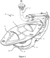
- FIGS 1-8 illustrate a disposable apparatus, generally designated 10, according to one embodiment of the present disclosure.
- the apparatus 10 can be configured for use in a counter flow centrifuge 20, and can be made using any of a variety of manufacturing techniques, such as injection-molding, blow-molding, machining, 3D printing, etc.
- the apparatus 10 can include one, two opposing, three or four vessels 12.
- the vessels 12 are formed by two opposing plates 12a, 12b.
- the plates 12a, 12b can be fixedly attached. When combined or attached, the plates 12a, 12b can form channels or passageways 13, which permit fluid to flow therethrough.
- each vessel 12 can have a conical shape, wherein a tip or small end of the cone is positioned outwardly from the geometric center of each plate 12a, 12b, and the wider end of each cone is positioned proximate to the geometric center of each plate 12a, 12b.
- fluid is designed to flow into each cone at the tip thereof, and out of each cone at an opening at the wider end of each cone.
- the flow can be reversed (i.e., into the wider end and out of the tip), for example to capture cell population in a small fluid slug.
- the vessels 12 are not limited to the size, shape and/or configuration shown and described herein, but can include any of a variety of sizes, shapes and/or configures.
- each vessel 12 can have one, two or more inlets and/or outlets.
- the apparatus 10 includes a handle assembly 14.
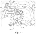
- the handle assembly 14 is designed to be grasped by a user when inserting the apparatus 10 into the counter flow centrifuge 20 and removing the apparatus 10 from the counter flow centrifuge 20.
- a projection or clip 32 can be positioned on the handle assembly 14 to facilitate engagement with at least the bowl 18 of the counter flow centrifuge 20 and removal of the handle assembly 14 from the counter flow centrifuge 20.
- the clip 32 can at least temporarily engage a ledge (not shown) for example, within the counter flow centrifuge 20.
- the clip 32 can be spring-biased.
- the handle assembly 14 can be a bearing support mechanism, as described below.
- a plurality of tubes 16 can extend through the handle assembly 14. More particularly, each tube 16 can extend from a tube set (not shown), through the handle assembly 14, and to at least one of the vessels 12.
- the tube set may include or be operated by a controller to dictate flow rates, flow paths, and/or the type of fluid supplied.
- Each tube 16 can be configured to allow fluid to flow between the tube set and/or one or more reservoirs 50 (shown schematically in Fig. 8 and understood by those skilled in the art) and at least one of the vessels 12.
- the reservoir(s) 50 can contain(s) fluid, including live cells or other material. The fluid can be pumped or otherwise caused to flow into at least one of the tubes 16.
- the fluid can be pumped into two of the tubes 16.
- Each tube 16 can correspond to or be connected to one of the channels 13, and each tube 16 can be formed of a flexible material.
- the tubes 16 may be positioned in a sheath 17 to protect the tubes 16.
- a first tube 16 is connected to the tip of the cone of a first one of the vessels 12, and a second tube 16 is connected to the tip of the cone of the second one of the vessels 12.
- a third tube 16 is connected to the opening at the wider end of the cone of the first one of the vessels 12, and a fourth tube 16 is connected to the opening at the wider end of the second one of the vessels 12.
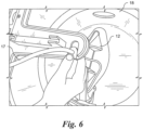
- a first bearing 26 can be located within an upper portion of the handle assembly 14, a second bearing 28 can be located within a lower portion of the handle assembly 14, and a third bearing 30 can be located proximate to and/or within a gear 24 (described in detail below).
- Each tube 16 can extend through each of the first, second and third bearings 26, 28.
- the gear 24 can be attached to each vessel 12, such that rotation of the gear 24 rotates the vessels 12. More particularly, the gear 24 can be positioned within a portion of the handle assembly 14 and an extension or pinion 24a of the gear 24 may extend upwardly through an opening of the handle assembly 14 and engage a bottom portion of the bottom plate 12b. At least a portion of the gear 24 may be exposed by another opening ( e.g., a window 25) of the handle assembly 14. As a result, the gear 24 can matingly engage and/or be driven by a rotor and/or a drive system, generally designated 40, (see Fig. 8 ) of or within the counter flow centrifuge 20.
- a rotor and/or a drive system generally designated 40, (see Fig. 8 ) of or within the counter flow centrifuge 20.
- the handle assembly 14 can be driven by another portion of the counter flow centrifuge 20, such as a different portion of the drive system within the counter flow centrifuge 20.
- the gear ratios of the drive system can determine the 2:1 speed ratio, such that step-down gearing precisely maintains the 2:1 ratio.
- the drive system can include a first drive system and a second drive system, such that both drive systems are separate and independent.
- An identification device 34 such as a radio-frequency identification (RFID) chip, can be located in a portion of the apparatus to contain and record certain information (such as the serial number, number of hours of use, and/or the number of rotations of the apparatus 10 within the counter flow centrifuge 20).
- RFID radio-frequency identification
- the identification device 34 can have read/write capability.
- the apparatus 10 is configured to be inserted into and removed from a bowl 18 of the counter flow centrifuge 20.
- the gear 24 and each vessel 12 can be rotated by the drive system at twice a speed of the handle assembly 14, which is rotated by a separate portion ( e.g., gear) of the drive system.
- Fluid can be supplied to or injected into the vessels 12 in a direction opposite to the centrifugal force applied to the vessels 12 (inward toward the geometric center vs. outward away from the geometric center). Fluid flow can be increased until equilibrium is established between the force of the fluid flow and the centrifugal force.
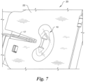
- the centrifuge 20 can create a temperature-control environment for the apparatus 10 when a lid 22 (see Fig. 7 ) is in a closed position.
- the temperature (or a temperature range) can be selectively adjusted by a user or automatically set.
- the apparatus 10 can be configured to be discarded after a single use.
- the rotor (and, therefore, the gear 24 and vessel(s) 12) can be rotated at up to several thousand (e.g., approximately 3,000) revolutions per minute (rpm), where the handle assembly 14 can be rotated at half that speed. More particularly, in one embodiment, the first bearing 26 can rotate in a first direction (e.g., counterclockwise) at approximately 1,500 rpm, and the second bearing 28 can rotate in a second direction (e.g., clockwise) at approximately 1,500 rpm. The vessel(s) 12 and the handle assembly 14 can rotate about the same axis of rotation.
- One method of the present disclosure includes opening the lid 22 of the counter flow centrifuge 20 and inserting the apparatus 10 at least partially into the bowl 18 of the counter flow centrifuge 20.
- the lid 22 can be closed to surround the apparatus 10, with at least a portion of the tubes 16 extending upwardly through an opening in the lid 22.
- the gear 24 of the apparatus 10 can then be driven such that the two opposing vessels 12 are rotated at twice a rotational speed of the handle assembly 10.
- fluid Prior, subsequent, or simultaneously to rotation of the gear 34, fluid can be pumped from the reservoir 50 into one, two or more of the tubes 16. Stated differently, the two opposing vessels 12 can be rotated such that centrifugal forces balance draft forces, allowing a bed of particles or cells to be held in suspension.
- the handle assembly 14 can be rotated at half the speed of the gear 34 to maintain a closed fluid path from the external environment to each rotating vessel 12 without the need for rotating seals.
- the lid 22 can be opened and the apparatus 10 can be removed from the counter flow centrifuge 20. Finally, the apparatus 10 can be discarded.
Landscapes
- Chemical & Material Sciences (AREA)
- Chemical Kinetics & Catalysis (AREA)
- Health & Medical Sciences (AREA)
- Analytical Chemistry (AREA)
- General Health & Medical Sciences (AREA)
- Hematology (AREA)
- Clinical Laboratory Science (AREA)
- Centrifugal Separators (AREA)
Claims (17)
- Gerät (10), das Folgendes aufweist:mindestens ein Gefäß, wobei das Gefäß (12), gebildet durch zwei gegenüberliegende Platten (12a, 12b), einen Einlass und einen Auslass aufweist;ein Zahnrad (24), das derart fest an mindestens einem Abschnitt des Gefäßes (12), angebracht ist, dass Drehung des Zahnrads das Gefäß (12) dreht, wobei das Zahnrad dazu ausgelegt ist, durch ein Antriebssystem (40) gedreht zu werden;eine Griffanordnung (14), die drehbar an dem Zahnrad (24) angebracht ist, wobei das Zahnrad (24) innerhalb eines Abschnitts der Griffanordnung (14) angeordnet ist,wobei die Griffanordnung (14) eine Öffnung darin aufweist, wobei eine Verlängerung oder ein Ritzel (24a) des Zahnrads (24) nach oben durch die Öffnung der Griffanordnung (14) verläuft, und wobei die Verlängerung oder das Ritzel (24a) des Zahnrads (24) in einen unteren Abschnitt einer unteren Platte (12b) der beiden gegenüberliegenden Platten (12a, 12b) von mindestens einem Gefäß eingreift; undwobei mindestens ein Abschnitt des Zahnrads (24) durch eine weitere Öffnung (25) der Griffanordnung (14) freiliegt und das Zahnrad (24) durch die weitere Öffnung (25) hindurch mit mindestens einem Abschnitt des Antriebssystems (40) eingreift, die Griffanordnung (14) dazu ausgelegt ist, durch das Antriebssystem (40) gedreht zu werden; undeine Vielzahl an Schläuchen (16), die sich durch die Griffanordnung (14) und zum Gefäß (12) erstrecken, wobei einer der Vielzahl an Schläuchen (16) mit dem Einlass des Gefäßes (12) verbunden ist und einer der Vielzahl an Schläuchen (16) mit dem Auslass des Gefäßes (12) verbunden ist,wobei das Zahnrad (24) mit der doppelten Geschwindigkeit der Griffanordnung (14) gedreht wird, wenn das Gerät (10) in eine Schüssel (18) eingesetzt wird, um den Stoff in dem mindestens einen Gefäß (12) zu suspendieren.
- Gerät (10) nach Anspruch 1, das ferner ein erstes Lager (26), das sich in einem oberen Abschnitt der Griffanordnung (14) befindet, und ein zweites Lager (28), das sich in einem unteren Abschnitt der Griffanordnung (14) befindet, und ein drittes Lager (30), das sich nahe dem Zahnrad (24) befindet, aufweist, wobei sich die Vielzahl an Schläuchen (16) durch jedes der Lager erstreckt.
- Gerät (10) nach Anspruch 1, wobei das Gerät (10) dazu ausgelegt ist, in die Schüssel (18) eingesetzt zu werden und daraus entfernt zu werden, und wobei das Gerät (10) dazu ausgelegt ist, nach einmaliger Verwendung entsorgt zu werden.
- Gerät (10) nach Anspruch 1, wobei die Vielzahl an Schläuchen (16) vier Schläuche aufweist, wobei die vier Schläuche dazu ausgelegt sind, es Fluid, das den Stoff enthält, zu gestatten, sich zu und von dem mindestens einen Gefäß (12) zu bewegen.
- Gerät (10) nach Anspruch 4, wobei das mindestens eine Gefäß (12) ein erstes Gefäß und ein zweites Gefäß aufweist, wobei das Gefäß (12) aus den zwei gegenüberliegenden Platten (12a, 12b) gebildet ist.
- Gerät (10) nach Anspruch 5, wobei jedes Gefäß (12) ein erstes Ende und ein gegenüberliegendes zweites Ende aufweist, wobei das erste Ende jedes Gefäßes (12) der Einlass ist, das zweite Ende jedes Gefäßes (12) der Auslass ist, ein Durchmesser des ersten Endes kleiner als ein Durchmesser des zweiten Endes ist, das erste Ende sich nahe einem Außenumfang der Platten (12a, 12b) befindet.
- Gerät (10) nach Anspruch 6, wobei die Vielzahl an Schläuchen (16) vier Schläuche aufweist, wobei jeder Schlauch aus einem im Allgemeinen biegsamen Material gebildet ist und betriebswirksam mit mindestens einem Behälter (50), der Fluid aufweist, verbunden ist.
- Gerät (10) nach Anspruch 7, wobei ein erster der Schläuche (16) mit dem ersten Ende des ersten Gefäßes verbunden ist, ein zweiter der Schläuche (16) mit dem ersten Ende des zweiten Gefäßes verbunden ist, ein dritter der Schläuche (16) mit dem zweiten Ende des ersten Gefäßes verbunden ist und ein vierter der Schläuche (16) mit dem zweiten Ende des zweiten Gefäßes verbunden ist.
- Gerät (10) nach Anspruch 8, wobei das Fluid durch das erste Ende davon in das erste Gefäß fließt und durch das zweite Ende davon aus jedem Gefäß fließt.
- Gerät nach Anspruch 1, wobei sich die Schüssel (18) und die Griffanordnung (14) mit der gleichen Drehzahl drehen.
- Gerät (10) nach Anspruch 1, wobei ein Vorsprung der Griffanordnung (14) mindestens einen Abschnitt der Schüssel (18) eingreift, wenn das Gerät (10) richtig in der Schüssel (18) eingesetzt ist.
- Gerät nach Anspruch 11, wobei der Vorsprung mittels einer Feder vorgespannt ist.
- Gerät nach Anspruch 1, das ferner einen RFID (Radio-Frequency Identification)-Chip, der sich auf oder in dem Gerät befindet, aufweist.
- Verfahren zum Durchführen von Gegenstromzentrifugation, wobei das Verfahren Folgendes aufweist:Einsetzen eines Geräts (10) in eine Schüssel (18), wobei das Gerät mindestens ein Gefäß (12), eine Griffanordnung (14) und eine Vielzahl an Schläuchen (16) aufweist, wobei sich jeder Schlauch von mindestens einem Behälter (50) durch die Griffanordnung (14) und zu dem mindestens einen Gefäß (12) erstreckt, wobei der Behälter (50) Fluid aufweist;Pumpen von Fluid von dem Behälter (50) in mindestens einen der Schläuche (16);Drehen des mindestens einen Gefäßes (12) mit der doppelten Geschwindigkeit der Griffanordnung (14), um den Stoff in dem Fluid in dem Gefäß (12) zu suspendieren, wobei sich die Schüssel (18) und die Griffanordnung (14) mit der gleichen Drehzahl drehen;Entfernen des Geräts (10) aus der Schüssel (18); undEntsorgen des Geräts (10).
- Verfahren nach Anspruch 14, wobei das oder jedes Gefäß (12) ein erstes Ende und ein gegenüberliegendes zweites Ende aufweist, wobei ein Durchmesser des ersten Endes kleiner als ein Durchmesser des zweiten Endes ist.
- Verfahren nach Anspruch 15, wobei das Fluid an dem ersten Ende davon in das oder jedes Gefäß (12) fließt und wobei das Fluid an dem zweiten Ende davon aus dem oder jedem Gefäß (12) fließt.
- Verfahren nach Anspruch 14, wobei das Gerät (10) durch Spritzgießen, Blasformen, Bearbeiten und/oder dreidimensionales Drucken gebildet wird.
Applications Claiming Priority (2)
| Application Number | Priority Date | Filing Date | Title |
|---|---|---|---|
| US14/879,163 US10099228B2 (en) | 2015-10-09 | 2015-10-09 | Apparatus for performing counter flow centrifugation and method of using same |
| PCT/US2016/052853 WO2017062176A1 (en) | 2015-10-09 | 2016-09-21 | Removable apparatus for a centrifuge and method of using same |
Publications (4)
| Publication Number | Publication Date |
|---|---|
| EP3359294A1 EP3359294A1 (de) | 2018-08-15 |
| EP3359294A4 EP3359294A4 (de) | 2019-05-22 |
| EP3359294B1 EP3359294B1 (de) | 2020-05-13 |
| EP3359294B2 true EP3359294B2 (de) | 2024-10-16 |
Family
ID=58488331
Family Applications (1)
| Application Number | Title | Priority Date | Filing Date |
|---|---|---|---|
| EP16854067.2A Active EP3359294B2 (de) | 2015-10-09 | 2016-09-21 | Abnehmbare vorrichtung für eine zentrifuge und verfahren zur verwendung davon |
Country Status (12)
| Country | Link |
|---|---|
| US (1) | US10099228B2 (de) |
| EP (1) | EP3359294B2 (de) |
| JP (1) | JP6957479B2 (de) |
| KR (1) | KR102581866B1 (de) |
| CN (1) | CN108367301B (de) |
| AU (1) | AU2016335122B2 (de) |
| CA (1) | CA3001302A1 (de) |
| DK (1) | DK3359294T4 (de) |
| ES (1) | ES2811331T5 (de) |
| FI (1) | FI3359294T4 (de) |
| RU (1) | RU2718754C2 (de) |
| WO (1) | WO2017062176A1 (de) |
Families Citing this family (12)
| Publication number | Priority date | Publication date | Assignee | Title |
|---|---|---|---|---|
| US10099228B2 (en) * | 2015-10-09 | 2018-10-16 | Invetech, Inc. | Apparatus for performing counter flow centrifugation and method of using same |
| US20180008990A1 (en) * | 2016-07-07 | 2018-01-11 | Tobi D. Mengle | Centrifugal mechanical separator produced by additive manufacturing |
| KR102657962B1 (ko) | 2017-05-12 | 2024-04-16 | 싸이노지 프로덕츠 피티와이 엘티디 | 소형 역류 원심 분리기 시스템 |
| US12138639B2 (en) | 2018-01-22 | 2024-11-12 | Scinogy Products Pty Ltd | System, method and controller for recovery of concentrated particles suspended in fluid |
| CA3175039A1 (en) | 2020-03-10 | 2021-09-16 | Cellares Corporation | Systems, devices, and methods for cell processing |
| US12180453B2 (en) | 2023-03-21 | 2024-12-31 | Cellares Corporation | Systems, devices, and methods for electroporation within a cell processing system |
| US12399193B2 (en) | 2023-05-05 | 2025-08-26 | Cellares Corporation | Systems, devices, and methods for combined cell processes |
| EP4464417A1 (de) * | 2023-05-17 | 2024-11-20 | Thermo Electron SAS | Einsätze für zentrifugenrotore, behälter und verfahren |
| US12337321B2 (en) | 2023-08-21 | 2025-06-24 | Cellares Corporation | Systems, devices, and methods for automatic cell sorting |
| US12305156B2 (en) | 2023-08-21 | 2025-05-20 | Cellares Corporation | Systems, devices, and methods for fluid control in a cell processing system |
| WO2025041047A1 (en) | 2023-08-21 | 2025-02-27 | Cellares Corporation | Bioreactors and methods of their use in automatic cell processing systems |
| US12492368B2 (en) | 2024-03-11 | 2025-12-09 | Cellares Corporation | Monitoring air pressure within a cell processing system |
Citations (17)
| Publication number | Priority date | Publication date | Assignee | Title |
|---|---|---|---|---|
| US3986442A (en) † | 1975-10-09 | 1976-10-19 | Baxter Laboratories, Inc. | Drive system for a centrifugal liquid processing system |
| US4113173A (en) † | 1975-03-27 | 1978-09-12 | Baxter Travenol Laboratories, Inc. | Centrifugal liquid processing apparatus |
| US4114802A (en) † | 1977-08-29 | 1978-09-19 | Baxter Travenol Laboratories, Inc. | Centrifugal apparatus with biaxial connector |
| US4163519A (en) † | 1977-11-01 | 1979-08-07 | Union Carbide Corporation | Compensating rotor |
| US4221322A (en) † | 1977-10-31 | 1980-09-09 | Union Carbide Corporation | Tube guide insert and constraint fittings for compensating rotor |
| US4950401A (en) † | 1986-09-12 | 1990-08-21 | Alfa-Laval Separation Ab | Centrifugal separator |
| US5525218A (en) † | 1993-10-29 | 1996-06-11 | Baxter International Inc. | Centrifuge with separable bowl and spool elements providing access to the separation chamber |
| US5989177A (en) † | 1997-04-11 | 1999-11-23 | Baxter International Inc. | Umbilicus gimbal with bearing retainer |
| WO2000061294A1 (fr) † | 1999-04-09 | 2000-10-19 | Haemonetics Corporation | Appareil de centrifugation de liquide et utilisation de cet appareil |
| EP1393811A1 (de) † | 2002-09-02 | 2004-03-03 | Biofluid Systems Société Anonyme | Vorrichtung zum Zentrifugieren einer Flüssigkeit und Zentrifugenbaugruppe |
| US7001321B1 (en) † | 1998-03-30 | 2006-02-21 | Baxter International Inc. | Carrier for holding a flexible fluid processing container |
| US20070104616A1 (en) † | 2005-10-06 | 2007-05-10 | Richard Keenan | Fluid handling cassette system for body fluid analyzer |
| US20120202673A1 (en) † | 2011-02-01 | 2012-08-09 | Runyon Matthew K | Centrifuge rotor for separation and processing of complex fluids |
| US20140038760A1 (en) † | 2011-09-22 | 2014-02-06 | Fenwal, Inc. | Drive system for centrifuge |
| US20140147862A1 (en) † | 2012-11-28 | 2014-05-29 | Samsung Electronics Co., Ltd. | Microfluidic apparatus and method of enriching target cells by using the same |
| WO2014204844A1 (en) † | 2013-06-18 | 2014-12-24 | Haemonetics Corporation | Rfid tag and method of securing same to object |
| US20150037882A1 (en) † | 2011-12-21 | 2015-02-05 | Lonza Walkersville, Inc | Scalable process for therapeutic cell concentration and residual clearance |
Family Cites Families (23)
| Publication number | Priority date | Publication date | Assignee | Title |
|---|---|---|---|---|
| US3286305A (en) | 1964-09-03 | 1966-11-22 | Rexall Drug Chemical | Apparatus for continuous manufacture of hollow articles |
| JPS50107565A (de) | 1974-01-29 | 1975-08-25 | ||
| SU1085503A3 (ru) * | 1975-03-27 | 1984-04-07 | Бакстер Травенол Лабораториз Инк.(Фирма) | Центрифуга дл биологических жидкостей |
| US4056224A (en) | 1975-03-27 | 1977-11-01 | Baxter Travenol Laboratories, Inc. | Flow system for centrifugal liquid processing apparatus |
| US4146172A (en) | 1977-10-18 | 1979-03-27 | Baxter Travenol Laboratories, Inc. | Centrifugal liquid processing system |
| JPS5819344B2 (ja) * | 1979-02-26 | 1983-04-18 | テルモ株式会社 | 流体の遠心分離装置 |
| JPS57151853A (en) * | 1981-03-16 | 1982-09-20 | Asahi Chem Ind Co Ltd | Liquid chromatography separation and its device |
| AU663160B2 (en) * | 1991-12-23 | 1995-09-28 | Baxter International Inc. | Centrifuge |
| DE4220232A1 (de) * | 1992-06-20 | 1993-12-23 | Fresenius Ag | Zentrifuge |
| US5665048A (en) * | 1995-12-22 | 1997-09-09 | Jorgensen; Glen | Circumferentially driven continuous flow centrifuge |
| EP1043072A1 (de) * | 1999-04-09 | 2000-10-11 | Jean-Denis Rochat | Zentrifugationsvorrichtung und Verwendung dieser Vorrichtung |
| US7008366B1 (en) * | 2000-10-27 | 2006-03-07 | Zymequest, Inc. | Circumferentially driven continuous flow centrifuge |
| US6589153B2 (en) * | 2001-09-24 | 2003-07-08 | Medtronic, Inc. | Blood centrifuge with exterior mounted, self-balancing collection chambers |
| US7201848B2 (en) | 2001-12-05 | 2007-04-10 | Gambro Bct, Inc. | Methods and apparatus for separation of particles |
| US20070102374A1 (en) | 2005-11-04 | 2007-05-10 | Gambro, Inc. | Blood processing apparatus with controlled cell capture chamber and method background of the invention |
| US8496609B2 (en) | 2007-07-05 | 2013-07-30 | Baxter International Inc. | Fluid delivery system with spiked cassette |
| DE102007054339B4 (de) | 2007-11-14 | 2009-10-29 | Miltenyi Biotec Gmbh | Vorrichtung zum Übertragen von Energie und/ oder eines Stoffes auf eine rotierende Einrichtung, sowie deren Verwendung |
| US9279133B2 (en) | 2008-07-16 | 2016-03-08 | Ksep Systems, Llc | Methods and systems for manipulating particles using a fluidized bed |
| DE102009040525B4 (de) * | 2009-09-08 | 2015-02-05 | Andreas Hettich Gmbh & Co. Kg | Zentrifuge zum Trennen von Vollblut in Blutkomponenten, sowie fluidisch kommunizierende Behälter zum Einsetzen in die Zentrifuge, sowie Verfahren zur Gewinnung eines hochangereichten Thrombozytenkonzentrats aus Vollblut |
| US9839920B2 (en) * | 2009-10-06 | 2017-12-12 | Satorius Stedim North America Inc. | Apparatus for manipulating particles using at least one chamber having an inlet and an opposed outlet |
| JP5667211B2 (ja) * | 2009-12-21 | 2015-02-12 | テルモ ビーシーティー、インコーポレーテッド | 低血漿キャリーオーバーを有する血小板を抽出するための装置 |
| DE102010003223B4 (de) * | 2010-03-24 | 2014-09-18 | Albert-Ludwigs-Universität Freiburg | Vorrichtung zum Einsetzen in einen Rotor einer Zentrifuge, Zentrifuge und Verfahren zum fluidischen Koppeln von Kavitäten |
| US10099228B2 (en) * | 2015-10-09 | 2018-10-16 | Invetech, Inc. | Apparatus for performing counter flow centrifugation and method of using same |
-
2015
- 2015-10-09 US US14/879,163 patent/US10099228B2/en active Active
-
2016
- 2016-09-21 WO PCT/US2016/052853 patent/WO2017062176A1/en not_active Ceased
- 2016-09-21 CA CA3001302A patent/CA3001302A1/en not_active Abandoned
- 2016-09-21 KR KR1020187013027A patent/KR102581866B1/ko active Active
- 2016-09-21 CN CN201680066045.6A patent/CN108367301B/zh active Active
- 2016-09-21 RU RU2018116650A patent/RU2718754C2/ru active
- 2016-09-21 EP EP16854067.2A patent/EP3359294B2/de active Active
- 2016-09-21 JP JP2018538044A patent/JP6957479B2/ja active Active
- 2016-09-21 FI FIEP16854067.2T patent/FI3359294T4/fi active
- 2016-09-21 AU AU2016335122A patent/AU2016335122B2/en active Active
- 2016-09-21 DK DK16854067.2T patent/DK3359294T4/da active
- 2016-09-21 ES ES16854067T patent/ES2811331T5/es active Active
Patent Citations (17)
| Publication number | Priority date | Publication date | Assignee | Title |
|---|---|---|---|---|
| US4113173A (en) † | 1975-03-27 | 1978-09-12 | Baxter Travenol Laboratories, Inc. | Centrifugal liquid processing apparatus |
| US3986442A (en) † | 1975-10-09 | 1976-10-19 | Baxter Laboratories, Inc. | Drive system for a centrifugal liquid processing system |
| US4114802A (en) † | 1977-08-29 | 1978-09-19 | Baxter Travenol Laboratories, Inc. | Centrifugal apparatus with biaxial connector |
| US4221322A (en) † | 1977-10-31 | 1980-09-09 | Union Carbide Corporation | Tube guide insert and constraint fittings for compensating rotor |
| US4163519A (en) † | 1977-11-01 | 1979-08-07 | Union Carbide Corporation | Compensating rotor |
| US4950401A (en) † | 1986-09-12 | 1990-08-21 | Alfa-Laval Separation Ab | Centrifugal separator |
| US5525218A (en) † | 1993-10-29 | 1996-06-11 | Baxter International Inc. | Centrifuge with separable bowl and spool elements providing access to the separation chamber |
| US5989177A (en) † | 1997-04-11 | 1999-11-23 | Baxter International Inc. | Umbilicus gimbal with bearing retainer |
| US7001321B1 (en) † | 1998-03-30 | 2006-02-21 | Baxter International Inc. | Carrier for holding a flexible fluid processing container |
| WO2000061294A1 (fr) † | 1999-04-09 | 2000-10-19 | Haemonetics Corporation | Appareil de centrifugation de liquide et utilisation de cet appareil |
| EP1393811A1 (de) † | 2002-09-02 | 2004-03-03 | Biofluid Systems Société Anonyme | Vorrichtung zum Zentrifugieren einer Flüssigkeit und Zentrifugenbaugruppe |
| US20070104616A1 (en) † | 2005-10-06 | 2007-05-10 | Richard Keenan | Fluid handling cassette system for body fluid analyzer |
| US20120202673A1 (en) † | 2011-02-01 | 2012-08-09 | Runyon Matthew K | Centrifuge rotor for separation and processing of complex fluids |
| US20140038760A1 (en) † | 2011-09-22 | 2014-02-06 | Fenwal, Inc. | Drive system for centrifuge |
| US20150037882A1 (en) † | 2011-12-21 | 2015-02-05 | Lonza Walkersville, Inc | Scalable process for therapeutic cell concentration and residual clearance |
| US20140147862A1 (en) † | 2012-11-28 | 2014-05-29 | Samsung Electronics Co., Ltd. | Microfluidic apparatus and method of enriching target cells by using the same |
| WO2014204844A1 (en) † | 2013-06-18 | 2014-12-24 | Haemonetics Corporation | Rfid tag and method of securing same to object |
Non-Patent Citations (1)
| Title |
|---|
| CHAD SCHWARZ: "Optimizing Cell Separation with Beckman Coulter's Centrifugal Elutriation System", 2014, XP055778510 † |
Also Published As
| Publication number | Publication date |
|---|---|
| EP3359294A1 (de) | 2018-08-15 |
| DK3359294T4 (da) | 2025-01-13 |
| JP6957479B2 (ja) | 2021-11-02 |
| KR102581866B1 (ko) | 2023-09-21 |
| CA3001302A1 (en) | 2017-04-13 |
| US20170100725A1 (en) | 2017-04-13 |
| ES2811331T3 (es) | 2021-03-11 |
| ES2811331T5 (en) | 2025-03-26 |
| CN108367301A (zh) | 2018-08-03 |
| RU2018116650A (ru) | 2019-11-11 |
| EP3359294B1 (de) | 2020-05-13 |
| DK3359294T3 (da) | 2020-08-10 |
| KR20180081062A (ko) | 2018-07-13 |
| AU2016335122B2 (en) | 2021-07-01 |
| RU2718754C2 (ru) | 2020-04-14 |
| JP2018529520A (ja) | 2018-10-11 |
| FI3359294T4 (fi) | 2024-12-05 |
| WO2017062176A1 (en) | 2017-04-13 |
| CN108367301B (zh) | 2020-09-18 |
| EP3359294A4 (de) | 2019-05-22 |
| AU2016335122A1 (en) | 2018-04-26 |
| RU2018116650A3 (de) | 2020-02-06 |
| US10099228B2 (en) | 2018-10-16 |
Similar Documents
| Publication | Publication Date | Title |
|---|---|---|
| EP3359294B2 (de) | Abnehmbare vorrichtung für eine zentrifuge und verfahren zur verwendung davon | |
| JP7248324B2 (ja) | コンパクトな逆流遠心分離システムおよびそれに用いる分離チャンバ | |
| US8226537B2 (en) | Blood processing apparatus with cell separation chamber with baffles | |
| CN104169590B (zh) | 用于泵送液体的流控模块、装置和方法 | |
| EP2717942B1 (de) | System zur bluttrennung mit einem schwerkraftventil zur steuerung einer trennkammer mit seitengewindebohrung | |
| US20020068674A1 (en) | Fluid separation devices, systems and/or methods using a fluid pressure driven and/or balanced configuration | |
| US10130947B2 (en) | Valving system for use in centrifugal microfluidic platforms | |
| US10166541B2 (en) | Centrifugal microfluidic platform for automated media exchange | |
| JP2018088831A (ja) | 細胞分離デバイス及び細胞分離システム | |
| JP6907183B2 (ja) | サンプル分離および収集のための方法および装置 | |
| WO2024064921A1 (en) | Pressure balancing across microfluidic devices | |
| JP6289062B2 (ja) | オーバーモールドなしの低コストアンビリカス | |
| US20250303031A1 (en) | Closed automated system and method for multiplex cell processing |
Legal Events
| Date | Code | Title | Description |
|---|---|---|---|
| STAA | Information on the status of an ep patent application or granted ep patent |
Free format text: STATUS: THE INTERNATIONAL PUBLICATION HAS BEEN MADE |
|
| PUAI | Public reference made under article 153(3) epc to a published international application that has entered the european phase |
Free format text: ORIGINAL CODE: 0009012 |
|
| STAA | Information on the status of an ep patent application or granted ep patent |
Free format text: STATUS: REQUEST FOR EXAMINATION WAS MADE |
|
| 17P | Request for examination filed |
Effective date: 20180406 |
|
| AK | Designated contracting states |
Kind code of ref document: A1 Designated state(s): AL AT BE BG CH CY CZ DE DK EE ES FI FR GB GR HR HU IE IS IT LI LT LU LV MC MK MT NL NO PL PT RO RS SE SI SK SM TR |
|
| AX | Request for extension of the european patent |
Extension state: BA ME |
|
| DAV | Request for validation of the european patent (deleted) | ||
| DAX | Request for extension of the european patent (deleted) | ||
| A4 | Supplementary search report drawn up and despatched |
Effective date: 20190418 |
|
| RIC1 | Information provided on ipc code assigned before grant |
Ipc: G01N 15/04 20060101ALI20190412BHEP Ipc: B04B 5/04 20060101ALI20190412BHEP Ipc: B04B 9/08 20060101ALI20190412BHEP Ipc: B04B 1/00 20060101AFI20190412BHEP Ipc: B04B 15/00 20060101ALI20190412BHEP Ipc: B04B 11/02 20060101ALI20190412BHEP Ipc: B01L 3/00 20060101ALI20190412BHEP Ipc: B01D 21/26 20060101ALI20190412BHEP |
|
| GRAP | Despatch of communication of intention to grant a patent |
Free format text: ORIGINAL CODE: EPIDOSNIGR1 |
|
| STAA | Information on the status of an ep patent application or granted ep patent |
Free format text: STATUS: GRANT OF PATENT IS INTENDED |
|
| INTG | Intention to grant announced |
Effective date: 20200108 |
|
| GRAS | Grant fee paid |
Free format text: ORIGINAL CODE: EPIDOSNIGR3 |
|
| GRAA | (expected) grant |
Free format text: ORIGINAL CODE: 0009210 |
|
| STAA | Information on the status of an ep patent application or granted ep patent |
Free format text: STATUS: THE PATENT HAS BEEN GRANTED |
|
| AK | Designated contracting states |
Kind code of ref document: B1 Designated state(s): AL AT BE BG CH CY CZ DE DK EE ES FI FR GB GR HR HU IE IS IT LI LT LU LV MC MK MT NL NO PL PT RO RS SE SI SK SM TR |
|
| REG | Reference to a national code |
Ref country code: GB Ref legal event code: FG4D |
|
| REG | Reference to a national code |
Ref country code: CH Ref legal event code: EP |
|
| REG | Reference to a national code |
Ref country code: DE Ref legal event code: R096 Ref document number: 602016036556 Country of ref document: DE |
|
| REG | Reference to a national code |
Ref country code: AT Ref legal event code: REF Ref document number: 1269547 Country of ref document: AT Kind code of ref document: T Effective date: 20200615 |
|
| REG | Reference to a national code |
Ref country code: CH Ref legal event code: NV Representative=s name: DR. LUSUARDI AG, CH |
|
| REG | Reference to a national code |
Ref country code: NL Ref legal event code: FP |
|
| REG | Reference to a national code |
Ref country code: DK Ref legal event code: T3 Effective date: 20200806 |
|
| REG | Reference to a national code |
Ref country code: SE Ref legal event code: TRGR |
|
| REG | Reference to a national code |
Ref country code: FI Ref legal event code: FGE |
|
| REG | Reference to a national code |
Ref country code: NO Ref legal event code: T2 Effective date: 20200513 |
|
| REG | Reference to a national code |
Ref country code: LT Ref legal event code: MG4D |
|
| PG25 | Lapsed in a contracting state [announced via postgrant information from national office to epo] |
Ref country code: LT Free format text: LAPSE BECAUSE OF FAILURE TO SUBMIT A TRANSLATION OF THE DESCRIPTION OR TO PAY THE FEE WITHIN THE PRESCRIBED TIME-LIMIT Effective date: 20200513 Ref country code: IS Free format text: LAPSE BECAUSE OF FAILURE TO SUBMIT A TRANSLATION OF THE DESCRIPTION OR TO PAY THE FEE WITHIN THE PRESCRIBED TIME-LIMIT Effective date: 20200913 Ref country code: GR Free format text: LAPSE BECAUSE OF FAILURE TO SUBMIT A TRANSLATION OF THE DESCRIPTION OR TO PAY THE FEE WITHIN THE PRESCRIBED TIME-LIMIT Effective date: 20200814 Ref country code: PT Free format text: LAPSE BECAUSE OF FAILURE TO SUBMIT A TRANSLATION OF THE DESCRIPTION OR TO PAY THE FEE WITHIN THE PRESCRIBED TIME-LIMIT Effective date: 20200914 |
|
| PG25 | Lapsed in a contracting state [announced via postgrant information from national office to epo] |
Ref country code: HR Free format text: LAPSE BECAUSE OF FAILURE TO SUBMIT A TRANSLATION OF THE DESCRIPTION OR TO PAY THE FEE WITHIN THE PRESCRIBED TIME-LIMIT Effective date: 20200513 Ref country code: RS Free format text: LAPSE BECAUSE OF FAILURE TO SUBMIT A TRANSLATION OF THE DESCRIPTION OR TO PAY THE FEE WITHIN THE PRESCRIBED TIME-LIMIT Effective date: 20200513 Ref country code: LV Free format text: LAPSE BECAUSE OF FAILURE TO SUBMIT A TRANSLATION OF THE DESCRIPTION OR TO PAY THE FEE WITHIN THE PRESCRIBED TIME-LIMIT Effective date: 20200513 Ref country code: BG Free format text: LAPSE BECAUSE OF FAILURE TO SUBMIT A TRANSLATION OF THE DESCRIPTION OR TO PAY THE FEE WITHIN THE PRESCRIBED TIME-LIMIT Effective date: 20200813 |
|
| PG25 | Lapsed in a contracting state [announced via postgrant information from national office to epo] |
Ref country code: AL Free format text: LAPSE BECAUSE OF FAILURE TO SUBMIT A TRANSLATION OF THE DESCRIPTION OR TO PAY THE FEE WITHIN THE PRESCRIBED TIME-LIMIT Effective date: 20200513 |
|
| REG | Reference to a national code |
Ref country code: DE Ref legal event code: R082 Ref document number: 602016036556 Country of ref document: DE Representative=s name: HL KEMPNER PATENTANWAELTE, SOLICITORS (ENGLAND, DE Ref country code: DE Ref legal event code: R082 Ref document number: 602016036556 Country of ref document: DE Representative=s name: HL KEMPNER PATENTANWALT, RECHTSANWALT, SOLICIT, DE |
|
| PG25 | Lapsed in a contracting state [announced via postgrant information from national office to epo] |
Ref country code: EE Free format text: LAPSE BECAUSE OF FAILURE TO SUBMIT A TRANSLATION OF THE DESCRIPTION OR TO PAY THE FEE WITHIN THE PRESCRIBED TIME-LIMIT Effective date: 20200513 Ref country code: SM Free format text: LAPSE BECAUSE OF FAILURE TO SUBMIT A TRANSLATION OF THE DESCRIPTION OR TO PAY THE FEE WITHIN THE PRESCRIBED TIME-LIMIT Effective date: 20200513 Ref country code: RO Free format text: LAPSE BECAUSE OF FAILURE TO SUBMIT A TRANSLATION OF THE DESCRIPTION OR TO PAY THE FEE WITHIN THE PRESCRIBED TIME-LIMIT Effective date: 20200513 |
|
| REG | Reference to a national code |
Ref country code: DE Ref legal event code: R026 Ref document number: 602016036556 Country of ref document: DE |
|
| PLBI | Opposition filed |
Free format text: ORIGINAL CODE: 0009260 |
|
| PG25 | Lapsed in a contracting state [announced via postgrant information from national office to epo] |
Ref country code: SK Free format text: LAPSE BECAUSE OF FAILURE TO SUBMIT A TRANSLATION OF THE DESCRIPTION OR TO PAY THE FEE WITHIN THE PRESCRIBED TIME-LIMIT Effective date: 20200513 Ref country code: PL Free format text: LAPSE BECAUSE OF FAILURE TO SUBMIT A TRANSLATION OF THE DESCRIPTION OR TO PAY THE FEE WITHIN THE PRESCRIBED TIME-LIMIT Effective date: 20200513 |
|
| PLAX | Notice of opposition and request to file observation + time limit sent |
Free format text: ORIGINAL CODE: EPIDOSNOBS2 |
|
| REG | Reference to a national code |
Ref country code: ES Ref legal event code: FG2A Ref document number: 2811331 Country of ref document: ES Kind code of ref document: T3 Effective date: 20210311 |
|
| REG | Reference to a national code |
Ref country code: FI Ref legal event code: MDE Opponent name: SARTORIUS STEDIM NORTH AMERICA INC. |
|
| 26 | Opposition filed |
Opponent name: SARTORIUS STEDIM NORTH AMERICA INC. Effective date: 20210211 |
|
| PLAB | Opposition data, opponent's data or that of the opponent's representative modified |
Free format text: ORIGINAL CODE: 0009299OPPO |
|
| PG25 | Lapsed in a contracting state [announced via postgrant information from national office to epo] |
Ref country code: SI Free format text: LAPSE BECAUSE OF FAILURE TO SUBMIT A TRANSLATION OF THE DESCRIPTION OR TO PAY THE FEE WITHIN THE PRESCRIBED TIME-LIMIT Effective date: 20200513 |
|
| PLAF | Information modified related to communication of a notice of opposition and request to file observations + time limit |
Free format text: ORIGINAL CODE: EPIDOSCOBS2 |
|
| R26 | Opposition filed (corrected) |
Opponent name: SARTORIUS STEDIM NORTH AMERICA INC. Effective date: 20210211 |
|
| PG25 | Lapsed in a contracting state [announced via postgrant information from national office to epo] |
Ref country code: LU Free format text: LAPSE BECAUSE OF NON-PAYMENT OF DUE FEES Effective date: 20200921 |
|
| PLAN | Information deleted related to communication of a notice of opposition and request to file observations + time limit |
Free format text: ORIGINAL CODE: EPIDOSDOBS2 |
|
| PLAX | Notice of opposition and request to file observation + time limit sent |
Free format text: ORIGINAL CODE: EPIDOSNOBS2 |
|
| PG25 | Lapsed in a contracting state [announced via postgrant information from national office to epo] |
Ref country code: IE Free format text: LAPSE BECAUSE OF NON-PAYMENT OF DUE FEES Effective date: 20200921 |
|
| PLBB | Reply of patent proprietor to notice(s) of opposition received |
Free format text: ORIGINAL CODE: EPIDOSNOBS3 |
|
| PG25 | Lapsed in a contracting state [announced via postgrant information from national office to epo] |
Ref country code: TR Free format text: LAPSE BECAUSE OF FAILURE TO SUBMIT A TRANSLATION OF THE DESCRIPTION OR TO PAY THE FEE WITHIN THE PRESCRIBED TIME-LIMIT Effective date: 20200513 Ref country code: MT Free format text: LAPSE BECAUSE OF FAILURE TO SUBMIT A TRANSLATION OF THE DESCRIPTION OR TO PAY THE FEE WITHIN THE PRESCRIBED TIME-LIMIT Effective date: 20200513 Ref country code: CY Free format text: LAPSE BECAUSE OF FAILURE TO SUBMIT A TRANSLATION OF THE DESCRIPTION OR TO PAY THE FEE WITHIN THE PRESCRIBED TIME-LIMIT Effective date: 20200513 |
|
| PG25 | Lapsed in a contracting state [announced via postgrant information from national office to epo] |
Ref country code: MK Free format text: LAPSE BECAUSE OF FAILURE TO SUBMIT A TRANSLATION OF THE DESCRIPTION OR TO PAY THE FEE WITHIN THE PRESCRIBED TIME-LIMIT Effective date: 20200513 Ref country code: MC Free format text: LAPSE BECAUSE OF FAILURE TO SUBMIT A TRANSLATION OF THE DESCRIPTION OR TO PAY THE FEE WITHIN THE PRESCRIBED TIME-LIMIT Effective date: 20200513 |
|
| APBM | Appeal reference recorded |
Free format text: ORIGINAL CODE: EPIDOSNREFNO |
|
| APBP | Date of receipt of notice of appeal recorded |
Free format text: ORIGINAL CODE: EPIDOSNNOA2O |
|
| APAH | Appeal reference modified |
Free format text: ORIGINAL CODE: EPIDOSCREFNO |
|
| APBQ | Date of receipt of statement of grounds of appeal recorded |
Free format text: ORIGINAL CODE: EPIDOSNNOA3O |
|
| P01 | Opt-out of the competence of the unified patent court (upc) registered |
Effective date: 20230606 |
|
| PGFP | Annual fee paid to national office [announced via postgrant information from national office to epo] |
Ref country code: ES Payment date: 20231002 Year of fee payment: 8 |
|
| APBU | Appeal procedure closed |
Free format text: ORIGINAL CODE: EPIDOSNNOA9O |
|
| RAP4 | Party data changed (patent owner data changed or rights of a patent transferred) |
Owner name: DOVER MOTION, INC. |
|
| RAP2 | Party data changed (patent owner data changed or rights of a patent transferred) |
Owner name: INVETECH IP LLC |
|
| PUAH | Patent maintained in amended form |
Free format text: ORIGINAL CODE: 0009272 |
|
| STAA | Information on the status of an ep patent application or granted ep patent |
Free format text: STATUS: PATENT MAINTAINED AS AMENDED |
|
| 27A | Patent maintained in amended form |
Effective date: 20241016 |
|
| AK | Designated contracting states |
Kind code of ref document: B2 Designated state(s): AL AT BE BG CH CY CZ DE DK EE ES FI FR GB GR HR HU IE IS IT LI LT LU LV MC MK MT NL NO PL PT RO RS SE SI SK SM TR |
|
| REG | Reference to a national code |
Ref country code: DE Ref legal event code: R102 Ref document number: 602016036556 Country of ref document: DE |
|
| REG | Reference to a national code |
Ref country code: NL Ref legal event code: FP |
|
| REG | Reference to a national code |
Ref country code: DE Ref legal event code: R082 Ref document number: 602016036556 Country of ref document: DE |
|
| REG | Reference to a national code |
Ref country code: SE Ref legal event code: RPEO |
|
| REG | Reference to a national code |
Ref country code: DK Ref legal event code: T4 Effective date: 20250106 |
|
| PGFP | Annual fee paid to national office [announced via postgrant information from national office to epo] |
Ref country code: CH Payment date: 20241001 Year of fee payment: 9 |
|
| REG | Reference to a national code |
Ref country code: NL Ref legal event code: PD Owner name: INVETECH IP LLC; US Free format text: DETAILS ASSIGNMENT: CHANGE OF OWNER(S), ASSIGNMENT; FORMER OWNER NAME: INVETECH, INC. Effective date: 20250221 |
|
| REG | Reference to a national code |
Ref country code: ES Ref legal event code: DC2A Ref document number: 2811331 Country of ref document: ES Kind code of ref document: T5 Effective date: 20250326 |
|
| REG | Reference to a national code |
Ref country code: GB Ref legal event code: 732E Free format text: REGISTERED BETWEEN 20250327 AND 20250402 |
|
| REG | Reference to a national code |
Ref country code: DE Ref legal event code: R081 Ref document number: 602016036556 Country of ref document: DE Owner name: INVETECH IP LLC, SAN DIEGO, US Free format text: FORMER OWNER: INVETECH, INC., SAN DIEGO, CA, US |
|
| REG | Reference to a national code |
Ref country code: AT Ref legal event code: PC Ref document number: 1269547 Country of ref document: AT Kind code of ref document: T Owner name: INVETECH IP LLC, US Effective date: 20250519 |
|
| REG | Reference to a national code |
Ref country code: CH Ref legal event code: U11 Free format text: ST27 STATUS EVENT CODE: U-0-0-U10-U11 (AS PROVIDED BY THE NATIONAL OFFICE) Effective date: 20251001 |
|
| PGFP | Annual fee paid to national office [announced via postgrant information from national office to epo] |
Ref country code: FI Payment date: 20250925 Year of fee payment: 10 |
|
| PGFP | Annual fee paid to national office [announced via postgrant information from national office to epo] |
Ref country code: DK Payment date: 20250924 Year of fee payment: 10 Ref country code: DE Payment date: 20250926 Year of fee payment: 10 |
|
| PGFP | Annual fee paid to national office [announced via postgrant information from national office to epo] |
Ref country code: NO Payment date: 20250917 Year of fee payment: 10 |
|
| PGFP | Annual fee paid to national office [announced via postgrant information from national office to epo] |
Ref country code: NL Payment date: 20250925 Year of fee payment: 10 Ref country code: IT Payment date: 20250922 Year of fee payment: 10 |
|
| PGFP | Annual fee paid to national office [announced via postgrant information from national office to epo] |
Ref country code: BE Payment date: 20250925 Year of fee payment: 10 Ref country code: GB Payment date: 20250923 Year of fee payment: 10 |
|
| PGFP | Annual fee paid to national office [announced via postgrant information from national office to epo] |
Ref country code: AT Payment date: 20250917 Year of fee payment: 10 Ref country code: FR Payment date: 20250925 Year of fee payment: 10 |
|
| PGFP | Annual fee paid to national office [announced via postgrant information from national office to epo] |
Ref country code: SE Payment date: 20250924 Year of fee payment: 10 |
|
| PGFP | Annual fee paid to national office [announced via postgrant information from national office to epo] |
Ref country code: CZ Payment date: 20250904 Year of fee payment: 10 |
|
| REG | Reference to a national code |
Ref country code: ES Ref legal event code: FD2A Effective date: 20251031 |