EP3359294B2 - Removable apparatus for a centrifuge and method of using same - Google Patents
Removable apparatus for a centrifuge and method of using same Download PDFInfo
- Publication number
- EP3359294B2 EP3359294B2 EP16854067.2A EP16854067A EP3359294B2 EP 3359294 B2 EP3359294 B2 EP 3359294B2 EP 16854067 A EP16854067 A EP 16854067A EP 3359294 B2 EP3359294 B2 EP 3359294B2
- Authority
- EP
- European Patent Office
- Prior art keywords
- vessel
- handle assembly
- tubes
- gear
- bowl
- Prior art date
- Legal status (The legal status is an assumption and is not a legal conclusion. Google has not performed a legal analysis and makes no representation as to the accuracy of the status listed.)
- Active
Links
Images


Classifications
-
- B—PERFORMING OPERATIONS; TRANSPORTING
- B04—CENTRIFUGAL APPARATUS OR MACHINES FOR CARRYING-OUT PHYSICAL OR CHEMICAL PROCESSES
- B04B—CENTRIFUGES
- B04B9/00—Drives specially designed for centrifuges; Arrangement or disposition of transmission gearing; Suspending or balancing rotary bowls
- B04B9/08—Arrangement or disposition of transmission gearing ; Couplings; Brakes
-
- B—PERFORMING OPERATIONS; TRANSPORTING
- B01—PHYSICAL OR CHEMICAL PROCESSES OR APPARATUS IN GENERAL
- B01D—SEPARATION
- B01D21/00—Separation of suspended solid particles from liquids by sedimentation
- B01D21/26—Separation of sediment aided by centrifugal force or centripetal force
- B01D21/262—Separation of sediment aided by centrifugal force or centripetal force by using a centrifuge
-
- B—PERFORMING OPERATIONS; TRANSPORTING
- B01—PHYSICAL OR CHEMICAL PROCESSES OR APPARATUS IN GENERAL
- B01L—CHEMICAL OR PHYSICAL LABORATORY APPARATUS FOR GENERAL USE
- B01L3/00—Containers or dishes for laboratory use, e.g. laboratory glassware; Droppers
- B01L3/50—Containers for the purpose of retaining a material to be analysed, e.g. test tubes
- B01L3/502—Containers for the purpose of retaining a material to be analysed, e.g. test tubes with fluid transport, e.g. in multi-compartment structures
- B01L3/5021—Test tubes specially adapted for centrifugation purposes
-
- B—PERFORMING OPERATIONS; TRANSPORTING
- B04—CENTRIFUGAL APPARATUS OR MACHINES FOR CARRYING-OUT PHYSICAL OR CHEMICAL PROCESSES
- B04B—CENTRIFUGES
- B04B1/00—Centrifuges with rotary bowls provided with solid jackets for separating predominantly liquid mixtures with or without solid particles
-
- B—PERFORMING OPERATIONS; TRANSPORTING
- B04—CENTRIFUGAL APPARATUS OR MACHINES FOR CARRYING-OUT PHYSICAL OR CHEMICAL PROCESSES
- B04B—CENTRIFUGES
- B04B5/00—Other centrifuges
- B04B5/04—Radial chamber apparatus for separating predominantly liquid mixtures, e.g. butyrometers
- B04B5/0442—Radial chamber apparatus for separating predominantly liquid mixtures, e.g. butyrometers with means for adding or withdrawing liquid substances during the centrifugation, e.g. continuous centrifugation
- B04B2005/0471—Radial chamber apparatus for separating predominantly liquid mixtures, e.g. butyrometers with means for adding or withdrawing liquid substances during the centrifugation, e.g. continuous centrifugation with additional elutriation separation of different particles
-
- B—PERFORMING OPERATIONS; TRANSPORTING
- B04—CENTRIFUGAL APPARATUS OR MACHINES FOR CARRYING-OUT PHYSICAL OR CHEMICAL PROCESSES
- B04B—CENTRIFUGES
- B04B5/00—Other centrifuges
- B04B5/04—Radial chamber apparatus for separating predominantly liquid mixtures, e.g. butyrometers
- B04B5/0442—Radial chamber apparatus for separating predominantly liquid mixtures, e.g. butyrometers with means for adding or withdrawing liquid substances during the centrifugation, e.g. continuous centrifugation
- B04B2005/0492—Radial chamber apparatus for separating predominantly liquid mixtures, e.g. butyrometers with means for adding or withdrawing liquid substances during the centrifugation, e.g. continuous centrifugation with fluid conveying umbilicus between stationary and rotary centrifuge parts
Definitions
- the present disclosure in one embodiment, is directed generally to a centrifuge, in which an apparatus is insertable into and removable from a bowl, and a method of installing or using same.
- Counter flow centrifugation is a technique that creates an environment where material, such as particles (e.g., live cells), is suspended between a centrifugal force and an inward-flowing suspension fluid as a fluidized bed.
- the fluidized bed can be used to capture the cells and allow exchange of the media they are supported in.
- Changes to the working or operating conditions of the centrifuge can be used to selectively drive cell populations from the fluidized bed, elutriate, and/or retain cells in the bed.
- Counter flow centrifugation enables removal of particulate contamination from a cell suspension, and enables increased viability of the retained cell population through cell viability through selective removal of dead cells. It is important for live cell processing that the system be sterile.
- US 5350514 discloses a centrifuge comprising a separation chamber, with which a duct is permanently connected, a main rotor, on which the separation chamber rotates, by means of a bearing arrangement, and a guide means on the main rotor for guiding the duct from the middle lower part of the separation chamber into a part at a higher level than the centrifuge.
- the present application overcomes the above-identified disadvantages of currently-available technology, and accomplishes the above and other objectives.
- the present application is directed to a counter flow centrifuge system that enables a complete aseptic disposable set incorporating counter flow centrifugation to be supplied without the need for additional sterile connections, and the installation of the rotating counter flow centrifuge elements can be achieved as a single, greatly simplified step.
- Such a design facilitates adoption of the technology by users and integration of the technology as part of larger processing system without complex installation procedures or the need for sterile connections.
- the present invention includes a combination of a disposable or removable housing or apparatus configured to be used with a bowl of a centrifuge.
- the apparatus can include one, two opposing, or more vessels forming part of a single plastic rotor attached to a handle assembly.
- the rotor can be aseptically connected to two, four or more fixed tubes via the handle assembly.
- the tubes can provide fluid inlet and outlet to the vessels.
- the rotor can be mounted to and driven by a gear at twice the rotational speed of the handle assembly.
- the handle assembly can contain a bearing for the gear and, therefore, rotor to pivot on.
- the handle assembly may be primarily responsible for retaining the tube(s) rotational mountings during rotation, and preventing the tubing from undesirably twisting.
- the rotor bearing and "skip-rope" tubes contained in the disposable housing facilitate quick and easy loading of the disposable into an accompanying centrifuge bowl assembly using a single lock-in action.
- the apparatus allows for various processing volumes dependent on the chosen disposable size variant. In one embodiment, the apparatus also allows for two simultaneous processes by providing two separate vessels on separate fluid circuits.
- the apparatus can be a rigid, plastic molded rotor containing two opposing vessels.
- the size of the vessels can be modified depending upon user's process requirements.
- Four polymeric tubes can be aseptically connected to the inlets of the molded rotor.
- the tubes can be configured to carry process fluids to and from each of the vessels.
- the tubes can run the full length of the apparatus in a "skip rope" fashion, and can pass through all of the components of the apparatus, most particularly the main rotor bearing.
- the main rotor bearing can attach to the polymer drive gear for an assembly connecting to the lower half of the molded rotor.
- the gear can interface or engage with another gear in the accompanying centrifuge bowl assembly.
- a handle assembly can contain or support a lower half of the gear.
- the handle assembly can be fastened to the bearing assembly.
- the handle assembly can support and protect the tubes and any sheathing surrounding the tubes.
- the handle assembly can include locating and locking features that interact with the accompanying centrifuge bowl to position and secure the apparatus.
- the sheathing can be formed of various polymer components, and can connect to an underside of the gear assembly.
- the tubes may run through a passageway in the sheath.
- the sheath can incorporate bearings, which interface with features in the handle assembly.
- the sheath can terminate at an anchor feature, which fixes the tubes and the sheath in a stationary position on the accompanying centrifuge bowl assembly.
- the apparatus can be loaded into a centrifuge bowl assembly.
- the apparatus can then be locked into position in the centrifuge bowl, such as by one or more features on the handle assembly and/or by securing the anchor component.
- the tubes can be pre-connected to a tube set on the centrifuge device.
- the tube set can control flow rates, connects various fluids, and/or controls one or more fluid paths to/from the vessel(s).
- the centrifuge bowl and the handle assembly can rotate together at a set rotational speed.
- the gearing in the centrifuge bowl can interface with at least a portion of the apparatus, thereby causing at least the rotor and vessels to rotate at twice the rate of the handle assembly.
- this speed differential allows the anchor end (e.g., upper end) of the tubes to remain stationary, while the molded rotor rotates at twice the speed of the centrifuge bowl (and the handle assembly) without twisting.
- the rotational speed and fluid flow rate By varying the rotational speed and fluid flow rate, various cell processing procedures can be carried out.
- the apparatus of the present disclosure is an improvement over existing technology, at least because the housing assembly facilitates quick and easy loading of the apparatus into the accompanying centrifuge bowl assembly.
- the molded rotor allows for various processing conditions dependent upon the chosen vessel size and/or shape.
- the molded rotor with the two separate vessels allows two processes to run simultaneously in the single apparatus on separate vessel circuits.
- the apparatus allows for quicker and easier use, as well as greater functionality and flexibility as compared to the prior art.
- the apparatus can be used to carry out a variety of cell processing procedures, such as cell/particle washing or media exchange, cell/particle volume reduction, cell/particle separation (elutriation), cell/particle removal (e.g., Red Blood Cell (RBC) debulking), and/or recirculation of cell/particle suspension through a CounterFlow Centrifuge (CFC) chamber.
- cell/particle washing or media exchange cell/particle volume reduction
- cell/particle separation elutriation
- cell/particle removal e.g., Red Blood Cell (RBC) debulking
- CFC CounterFlow Centrifuge
- the handle assembly described above can be replaced with a fully enclosed cylindrical or other shaped housing.
- the handle assembly could be reduced to simply enclose or support the gear and lower sheath bearing.
- the accompanying centrifuge device could enclose or support any remaining components.
- the handle assembly can also include alternative bearing retaining features, such as one or more clips, press fits, etc.
- a combination can include a counter flow centrifuge having a bowl and a drive system.
- An apparatus is configured for use in the counter flow centrifuge.
- the apparatus can include at least two vessels. Each vessel can include an inlet and an outlet.
- a gear can be fixedly attached to at least a portion of each vessel such that rotation of the gear rotates the vessels.
- the gear can be configured to be rotated by the drive system of the counter flow centrifuge.
- a handle assembly can be rotatably attached to the gear.
- the handle assembly can be configured to be rotated by the drive system of the counter flow centrifuge.
- a plurality of tubes can extend through the handle assembly and to the vessels.
- One of the plurality of tubes can be connected to the inlet of each vessel and one of the plurality of tubes can be connected to the outlet of each vessel.
- the gear can be rotated at twice a speed of the handle assembly when the apparatus is inserted into the bowl of the counter flow centrifuge to suspend material in the at least one vessel when fluid containing the material flows from a reservoir, through the tubes and into the vessels.
- each vessel has a first end and an opposing second end.
- the first end of each vessel can be the inlet.
- the second end of each vessel can be the outlet.
- a diameter of the first end can be smaller than a diameter of the second end to form a generally conical shape.
- the first end can be positioned proximate an outer periphery of the plates.
- a first one of the plurality tubes can be connected to the first end of the first vessel.
- a second one of the tubes can be connected to the first end of the second vessel.
- a third one of the tubes can be connected to the second end of the first vessel.
- a fourth one of the tubes can be connected to the second end of the second vessel.
- FIGS 1-8 illustrate a disposable apparatus, generally designated 10, according to one embodiment of the present disclosure.
- the apparatus 10 can be configured for use in a counter flow centrifuge 20, and can be made using any of a variety of manufacturing techniques, such as injection-molding, blow-molding, machining, 3D printing, etc.
- the apparatus 10 can include one, two opposing, three or four vessels 12.
- the vessels 12 are formed by two opposing plates 12a, 12b.
- the plates 12a, 12b can be fixedly attached. When combined or attached, the plates 12a, 12b can form channels or passageways 13, which permit fluid to flow therethrough.
- each vessel 12 can have a conical shape, wherein a tip or small end of the cone is positioned outwardly from the geometric center of each plate 12a, 12b, and the wider end of each cone is positioned proximate to the geometric center of each plate 12a, 12b.
- fluid is designed to flow into each cone at the tip thereof, and out of each cone at an opening at the wider end of each cone.
- the flow can be reversed (i.e., into the wider end and out of the tip), for example to capture cell population in a small fluid slug.
- the vessels 12 are not limited to the size, shape and/or configuration shown and described herein, but can include any of a variety of sizes, shapes and/or configures.
- each vessel 12 can have one, two or more inlets and/or outlets.
- the apparatus 10 includes a handle assembly 14.
- the handle assembly 14 is designed to be grasped by a user when inserting the apparatus 10 into the counter flow centrifuge 20 and removing the apparatus 10 from the counter flow centrifuge 20.
- a projection or clip 32 can be positioned on the handle assembly 14 to facilitate engagement with at least the bowl 18 of the counter flow centrifuge 20 and removal of the handle assembly 14 from the counter flow centrifuge 20.
- the clip 32 can at least temporarily engage a ledge (not shown) for example, within the counter flow centrifuge 20.
- the clip 32 can be spring-biased.
- the handle assembly 14 can be a bearing support mechanism, as described below.
- a plurality of tubes 16 can extend through the handle assembly 14. More particularly, each tube 16 can extend from a tube set (not shown), through the handle assembly 14, and to at least one of the vessels 12.
- the tube set may include or be operated by a controller to dictate flow rates, flow paths, and/or the type of fluid supplied.
- Each tube 16 can be configured to allow fluid to flow between the tube set and/or one or more reservoirs 50 (shown schematically in Fig. 8 and understood by those skilled in the art) and at least one of the vessels 12.
- the reservoir(s) 50 can contain(s) fluid, including live cells or other material. The fluid can be pumped or otherwise caused to flow into at least one of the tubes 16.
- the fluid can be pumped into two of the tubes 16.
- Each tube 16 can correspond to or be connected to one of the channels 13, and each tube 16 can be formed of a flexible material.
- the tubes 16 may be positioned in a sheath 17 to protect the tubes 16.
- a first tube 16 is connected to the tip of the cone of a first one of the vessels 12, and a second tube 16 is connected to the tip of the cone of the second one of the vessels 12.
- a third tube 16 is connected to the opening at the wider end of the cone of the first one of the vessels 12, and a fourth tube 16 is connected to the opening at the wider end of the second one of the vessels 12.
- a first bearing 26 can be located within an upper portion of the handle assembly 14, a second bearing 28 can be located within a lower portion of the handle assembly 14, and a third bearing 30 can be located proximate to and/or within a gear 24 (described in detail below).
- Each tube 16 can extend through each of the first, second and third bearings 26, 28.
- the gear 24 can be attached to each vessel 12, such that rotation of the gear 24 rotates the vessels 12. More particularly, the gear 24 can be positioned within a portion of the handle assembly 14 and an extension or pinion 24a of the gear 24 may extend upwardly through an opening of the handle assembly 14 and engage a bottom portion of the bottom plate 12b. At least a portion of the gear 24 may be exposed by another opening ( e.g., a window 25) of the handle assembly 14. As a result, the gear 24 can matingly engage and/or be driven by a rotor and/or a drive system, generally designated 40, (see Fig. 8 ) of or within the counter flow centrifuge 20.
- a rotor and/or a drive system generally designated 40, (see Fig. 8 ) of or within the counter flow centrifuge 20.
- the handle assembly 14 can be driven by another portion of the counter flow centrifuge 20, such as a different portion of the drive system within the counter flow centrifuge 20.
- the gear ratios of the drive system can determine the 2:1 speed ratio, such that step-down gearing precisely maintains the 2:1 ratio.
- the drive system can include a first drive system and a second drive system, such that both drive systems are separate and independent.
- An identification device 34 such as a radio-frequency identification (RFID) chip, can be located in a portion of the apparatus to contain and record certain information (such as the serial number, number of hours of use, and/or the number of rotations of the apparatus 10 within the counter flow centrifuge 20).
- RFID radio-frequency identification
- the identification device 34 can have read/write capability.
- the apparatus 10 is configured to be inserted into and removed from a bowl 18 of the counter flow centrifuge 20.
- the gear 24 and each vessel 12 can be rotated by the drive system at twice a speed of the handle assembly 14, which is rotated by a separate portion ( e.g., gear) of the drive system.
- Fluid can be supplied to or injected into the vessels 12 in a direction opposite to the centrifugal force applied to the vessels 12 (inward toward the geometric center vs. outward away from the geometric center). Fluid flow can be increased until equilibrium is established between the force of the fluid flow and the centrifugal force.
- the centrifuge 20 can create a temperature-control environment for the apparatus 10 when a lid 22 (see Fig. 7 ) is in a closed position.
- the temperature (or a temperature range) can be selectively adjusted by a user or automatically set.
- the apparatus 10 can be configured to be discarded after a single use.
- the rotor (and, therefore, the gear 24 and vessel(s) 12) can be rotated at up to several thousand (e.g., approximately 3,000) revolutions per minute (rpm), where the handle assembly 14 can be rotated at half that speed. More particularly, in one embodiment, the first bearing 26 can rotate in a first direction (e.g., counterclockwise) at approximately 1,500 rpm, and the second bearing 28 can rotate in a second direction (e.g., clockwise) at approximately 1,500 rpm. The vessel(s) 12 and the handle assembly 14 can rotate about the same axis of rotation.
- One method of the present disclosure includes opening the lid 22 of the counter flow centrifuge 20 and inserting the apparatus 10 at least partially into the bowl 18 of the counter flow centrifuge 20.
- the lid 22 can be closed to surround the apparatus 10, with at least a portion of the tubes 16 extending upwardly through an opening in the lid 22.
- the gear 24 of the apparatus 10 can then be driven such that the two opposing vessels 12 are rotated at twice a rotational speed of the handle assembly 10.
- fluid Prior, subsequent, or simultaneously to rotation of the gear 34, fluid can be pumped from the reservoir 50 into one, two or more of the tubes 16. Stated differently, the two opposing vessels 12 can be rotated such that centrifugal forces balance draft forces, allowing a bed of particles or cells to be held in suspension.
- the handle assembly 14 can be rotated at half the speed of the gear 34 to maintain a closed fluid path from the external environment to each rotating vessel 12 without the need for rotating seals.
- the lid 22 can be opened and the apparatus 10 can be removed from the counter flow centrifuge 20. Finally, the apparatus 10 can be discarded.
Landscapes
- Chemical & Material Sciences (AREA)
- Chemical Kinetics & Catalysis (AREA)
- Health & Medical Sciences (AREA)
- Analytical Chemistry (AREA)
- General Health & Medical Sciences (AREA)
- Hematology (AREA)
- Clinical Laboratory Science (AREA)
- Centrifugal Separators (AREA)
Description
- This application claims priority to
U.S. Non-Provisional Application No. 14/879,163, filed on October 9, 2015 - The present disclosure, in one embodiment, is directed generally to a centrifuge, in which an apparatus is insertable into and removable from a bowl, and a method of installing or using same.
- The ability to process animal and human cells is a primary requirement for laboratory research, cell expansion and the cell therapeutics market. There is an increasing use of live, animal and human-derived, cells for therapeutic use. Such use is creating demand for technologies that are uniquely aligned for dealing with live cells as the final product. Examples of known biopharmaceutical manufacture methods are disclosed in
U.S. Patent No. 7,588,692 and U.S. Patent Application Publication No.2011/0207225 . - Counter flow centrifugation is a technique that creates an environment where material, such as particles (e.g., live cells), is suspended between a centrifugal force and an inward-flowing suspension fluid as a fluidized bed. The fluidized bed can be used to capture the cells and allow exchange of the media they are supported in. Changes to the working or operating conditions of the centrifuge can be used to selectively drive cell populations from the fluidized bed, elutriate, and/or retain cells in the bed. Counter flow centrifugation enables removal of particulate contamination from a cell suspension, and enables increased viability of the retained cell population through cell viability through selective removal of dead cells. It is important for live cell processing that the system be sterile.
- To achieve a robust, closed and/or aseptic fluidic system, one skilled in the art may know to use a "skip rope" plumbing design in a counter flow centrifugation system (see, e.g.,
U.S. Publication No. 2010/0261596 by Schimmelpfennig, et al. orU.S. Publication No. 2012/0270717 by Mehta et al. ). Such a design eliminates the need for sliding seals between the stationary and rotating elements. Currently available systems require a complicated, time-consuming and error-prone process to install the "skip rope," and are limited to a single vessel size, which restricts functionality. -
US 5350514 discloses a centrifuge comprising a separation chamber, with which a duct is permanently connected, a main rotor, on which the separation chamber rotates, by means of a bearing arrangement, and a guide means on the main rotor for guiding the duct from the middle lower part of the separation chamber into a part at a higher level than the centrifuge. - The present invention overcomes the above-identified disadvantages of currently-available technology, and accomplishes the above and other objectives. For example, in one embodiment, the present application is directed to a counter flow centrifuge system that enables a complete aseptic disposable set incorporating counter flow centrifugation to be supplied without the need for additional sterile connections, and the installation of the rotating counter flow centrifuge elements can be achieved as a single, greatly simplified step. Such a design facilitates adoption of the technology by users and integration of the technology as part of larger processing system without complex installation procedures or the need for sterile connections.
- The foregoing summary, as well as the following detailed description of the invention, will be better understood when read in conjunction with the appended drawings. For the purpose of illustrating the invention, there are shown in the drawings various illustrative embodiments. It should be understood, however, that the invention is not limited to the precise arrangements and instrumentalities shown. In the drawings:
-
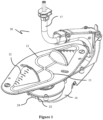
Figure 1 is a top perspective view of an apparatus according to an embodiment of the present disclosure; -
Figure 2 is a cross-sectional view of the apparatus ofFig. 1 ; -
Figure 3 is a partially exploded view of the apparatus ofFig. 1 ; -
Figure 4 is a side elevation view of the apparatus ofFig. 1 ; -
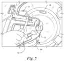
Figure 5 is top perspective view of the apparatus being at least partially inserted into a bowl; -
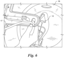
Figure 6 is another top perspective view of the apparatus positioned at least partially within the bowl, wherein a cover of the centrifuge is shown in an open position; -
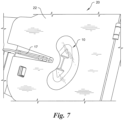
Figure 7 is another top perspective view of the apparatus positioned within the bowl, wherein the cover of the centrifuge is shown in a closed position; and -
Figure 8 is another perspective view of at least portions of a drive system of the apparatus. - Certain terminology is used in the following description for convenience only and is not limiting. The words "lower" and "upper" designate directions in the drawings to which reference is made. Unless specifically set forth herein, the terms "a," "an" and "the" are not limited to one element but instead should be read as meaning "at least one." The terminology includes the words noted above, derivatives thereof and words of similar import.
- In one embodiment, the present invention includes a combination of a disposable or removable housing or apparatus configured to be used with a bowl of a centrifuge. The apparatus can include one, two opposing, or more vessels forming part of a single plastic rotor attached to a handle assembly. The rotor can be aseptically connected to two, four or more fixed tubes via the handle assembly. The tubes can provide fluid inlet and outlet to the vessels. The rotor can be mounted to and driven by a gear at twice the rotational speed of the handle assembly. The handle assembly can contain a bearing for the gear and, therefore, rotor to pivot on. The handle assembly may be primarily responsible for retaining the tube(s) rotational mountings during rotation, and preventing the tubing from undesirably twisting.
- The rotor bearing and "skip-rope" tubes contained in the disposable housing facilitate quick and easy loading of the disposable into an accompanying centrifuge bowl assembly using a single lock-in action. The apparatus allows for various processing volumes dependent on the chosen disposable size variant. In one embodiment, the apparatus also allows for two simultaneous processes by providing two separate vessels on separate fluid circuits.
- More particularly, in one embodiment, the apparatus can be a rigid, plastic molded rotor containing two opposing vessels. The size of the vessels can be modified depending upon user's process requirements. Four polymeric tubes can be aseptically connected to the inlets of the molded rotor. The tubes can be configured to carry process fluids to and from each of the vessels. The tubes can run the full length of the apparatus in a "skip rope" fashion, and can pass through all of the components of the apparatus, most particularly the main rotor bearing. The main rotor bearing can attach to the polymer drive gear for an assembly connecting to the lower half of the molded rotor. The gear can interface or engage with another gear in the accompanying centrifuge bowl assembly.
- A handle assembly can contain or support a lower half of the gear. The handle assembly can be fastened to the bearing assembly. The handle assembly can support and protect the tubes and any sheathing surrounding the tubes. The handle assembly can include locating and locking features that interact with the accompanying centrifuge bowl to position and secure the apparatus. The sheathing can be formed of various polymer components, and can connect to an underside of the gear assembly. The tubes may run through a passageway in the sheath. The sheath can incorporate bearings, which interface with features in the handle assembly. The sheath can terminate at an anchor feature, which fixes the tubes and the sheath in a stationary position on the accompanying centrifuge bowl assembly.
- In operation, the apparatus can be loaded into a centrifuge bowl assembly. The apparatus can then be locked into position in the centrifuge bowl, such as by one or more features on the handle assembly and/or by securing the anchor component. The tubes can be pre-connected to a tube set on the centrifuge device. The tube set can control flow rates, connects various fluids, and/or controls one or more fluid paths to/from the vessel(s). The centrifuge bowl and the handle assembly can rotate together at a set rotational speed. The gearing in the centrifuge bowl can interface with at least a portion of the apparatus, thereby causing at least the rotor and vessels to rotate at twice the rate of the handle assembly. With the "skip rope" configuration of the tubes, this speed differential allows the anchor end (e.g., upper end) of the tubes to remain stationary, while the molded rotor rotates at twice the speed of the centrifuge bowl (and the handle assembly) without twisting. By varying the rotational speed and fluid flow rate, various cell processing procedures can be carried out.
- The apparatus of the present disclosure is an improvement over existing technology, at least because the housing assembly facilitates quick and easy loading of the apparatus into the accompanying centrifuge bowl assembly. In addition, the molded rotor allows for various processing conditions dependent upon the chosen vessel size and/or shape. Furthermore, the molded rotor with the two separate vessels allows two processes to run simultaneously in the single apparatus on separate vessel circuits. Thus, the apparatus allows for quicker and easier use, as well as greater functionality and flexibility as compared to the prior art. The apparatus can be used to carry out a variety of cell processing procedures, such as cell/particle washing or media exchange, cell/particle volume reduction, cell/particle separation (elutriation), cell/particle removal (e.g., Red Blood Cell (RBC) debulking), and/or recirculation of cell/particle suspension through a CounterFlow Centrifuge (CFC) chamber.
- In other embodiments, the handle assembly described above can be replaced with a fully enclosed cylindrical or other shaped housing. Alternatively, the handle assembly could be reduced to simply enclose or support the gear and lower sheath bearing. The accompanying centrifuge device could enclose or support any remaining components. The handle assembly can also include alternative bearing retaining features, such as one or more clips, press fits, etc.
- In one embodiment, a combination can include a counter flow centrifuge having a bowl and a drive system. An apparatus is configured for use in the counter flow centrifuge. The apparatus can include at least two vessels. Each vessel can include an inlet and an outlet. A gear can be fixedly attached to at least a portion of each vessel such that rotation of the gear rotates the vessels. The gear can be configured to be rotated by the drive system of the counter flow centrifuge. A handle assembly can be rotatably attached to the gear. The handle assembly can be configured to be rotated by the drive system of the counter flow centrifuge. A plurality of tubes can extend through the handle assembly and to the vessels. One of the plurality of tubes can be connected to the inlet of each vessel and one of the plurality of tubes can be connected to the outlet of each vessel. In one embodiment, the gear can be rotated at twice a speed of the handle assembly when the apparatus is inserted into the bowl of the counter flow centrifuge to suspend material in the at least one vessel when fluid containing the material flows from a reservoir, through the tubes and into the vessels.
- In one embodiment, each vessel has a first end and an opposing second end. The first end of each vessel can be the inlet. The second end of each vessel can be the outlet. A diameter of the first end can be smaller than a diameter of the second end to form a generally conical shape. The first end can be positioned proximate an outer periphery of the plates. A first one of the plurality tubes can be connected to the first end of the first vessel. A second one of the tubes can be connected to the first end of the second vessel. A third one of the tubes can be connected to the second end of the first vessel. A fourth one of the tubes can be connected to the second end of the second vessel.
-
Figures 1-8 illustrate a disposable apparatus, generally designated 10, according to one embodiment of the present disclosure. Theapparatus 10 can be configured for use in acounter flow centrifuge 20, and can be made using any of a variety of manufacturing techniques, such as injection-molding, blow-molding, machining, 3D printing, etc. Theapparatus 10 can include one, two opposing, three or fourvessels 12. Thevessels 12 are formed by two opposingplates plates plates passageways 13, which permit fluid to flow therethrough. - In one embodiment, each
vessel 12 can have a conical shape, wherein a tip or small end of the cone is positioned outwardly from the geometric center of eachplate plate vessels 12 are not limited to the size, shape and/or configuration shown and described herein, but can include any of a variety of sizes, shapes and/or configures. In addition, eachvessel 12 can have one, two or more inlets and/or outlets. - The
apparatus 10 includes ahandle assembly 14. Thehandle assembly 14 is designed to be grasped by a user when inserting theapparatus 10 into thecounter flow centrifuge 20 and removing theapparatus 10 from thecounter flow centrifuge 20. A projection orclip 32 can be positioned on thehandle assembly 14 to facilitate engagement with at least thebowl 18 of thecounter flow centrifuge 20 and removal of thehandle assembly 14 from thecounter flow centrifuge 20. Theclip 32 can at least temporarily engage a ledge (not shown) for example, within thecounter flow centrifuge 20. Theclip 32 can be spring-biased. Thehandle assembly 14 can be a bearing support mechanism, as described below. - A plurality of tubes 16 (e.g., four) can extend through the
handle assembly 14. More particularly, eachtube 16 can extend from a tube set (not shown), through thehandle assembly 14, and to at least one of thevessels 12. The tube set may include or be operated by a controller to dictate flow rates, flow paths, and/or the type of fluid supplied. Eachtube 16 can be configured to allow fluid to flow between the tube set and/or one or more reservoirs 50 (shown schematically inFig. 8 and understood by those skilled in the art) and at least one of thevessels 12. In one embodiment, the reservoir(s) 50 can contain(s) fluid, including live cells or other material. The fluid can be pumped or otherwise caused to flow into at least one of thetubes 16. In an embodiment including fourtubes 16 and twovessels 12, the fluid can be pumped into two of thetubes 16. Eachtube 16 can correspond to or be connected to one of thechannels 13, and eachtube 16 can be formed of a flexible material. Thetubes 16 may be positioned in asheath 17 to protect thetubes 16. - In one of the embodiments, a
first tube 16 is connected to the tip of the cone of a first one of thevessels 12, and asecond tube 16 is connected to the tip of the cone of the second one of thevessels 12. In addition, athird tube 16 is connected to the opening at the wider end of the cone of the first one of thevessels 12, and afourth tube 16 is connected to the opening at the wider end of the second one of thevessels 12. Thus, fluid flows into thevessels 12 via the first andsecond tubes 16, and fluid exits thevessels 12 via the third andfourth tubes 16. - A
first bearing 26 can be located within an upper portion of thehandle assembly 14, asecond bearing 28 can be located within a lower portion of thehandle assembly 14, and athird bearing 30 can be located proximate to and/or within a gear 24 (described in detail below). Eachtube 16 can extend through each of the first, second andthird bearings - As shown in
Figures 3 and8 , thegear 24 can be attached to eachvessel 12, such that rotation of thegear 24 rotates thevessels 12. More particularly, thegear 24 can be positioned within a portion of thehandle assembly 14 and an extension orpinion 24a of thegear 24 may extend upwardly through an opening of thehandle assembly 14 and engage a bottom portion of thebottom plate 12b. At least a portion of thegear 24 may be exposed by another opening (e.g., a window 25) of thehandle assembly 14. As a result, thegear 24 can matingly engage and/or be driven by a rotor and/or a drive system, generally designated 40, (seeFig. 8 ) of or within thecounter flow centrifuge 20. Thehandle assembly 14 can be driven by another portion of thecounter flow centrifuge 20, such as a different portion of the drive system within thecounter flow centrifuge 20. The gear ratios of the drive system can determine the 2:1 speed ratio, such that step-down gearing precisely maintains the 2:1 ratio. In one embodiment, the drive system can include a first drive system and a second drive system, such that both drive systems are separate and independent. - An
identification device 34, such as a radio-frequency identification (RFID) chip, can be located in a portion of the apparatus to contain and record certain information (such as the serial number, number of hours of use, and/or the number of rotations of theapparatus 10 within the counter flow centrifuge 20). Theidentification device 34 can have read/write capability. - In operation, the
apparatus 10 is configured to be inserted into and removed from abowl 18 of thecounter flow centrifuge 20. When theapparatus 10 is inserted into thebowl 18 of thecounter flow centrifuge 20, thegear 24 and eachvessel 12 can be rotated by the drive system at twice a speed of thehandle assembly 14, which is rotated by a separate portion (e.g., gear) of the drive system. Fluid can be supplied to or injected into thevessels 12 in a direction opposite to the centrifugal force applied to the vessels 12 (inward toward the geometric center vs. outward away from the geometric center). Fluid flow can be increased until equilibrium is established between the force of the fluid flow and the centrifugal force. This allows material (e.g., cells) to be held or suspended in a medium, and the medium can be changed or replaced, if desired. Thecentrifuge 20 can create a temperature-control environment for theapparatus 10 when a lid 22 (seeFig. 7 ) is in a closed position. The temperature (or a temperature range) can be selectively adjusted by a user or automatically set. Theapparatus 10 can be configured to be discarded after a single use. - In one embodiment, the rotor (and, therefore, the
gear 24 and vessel(s) 12) can be rotated at up to several thousand (e.g., approximately 3,000) revolutions per minute (rpm), where thehandle assembly 14 can be rotated at half that speed. More particularly, in one embodiment, thefirst bearing 26 can rotate in a first direction (e.g., counterclockwise) at approximately 1,500 rpm, and thesecond bearing 28 can rotate in a second direction (e.g., clockwise) at approximately 1,500 rpm. The vessel(s) 12 and thehandle assembly 14 can rotate about the same axis of rotation. - One method of the present disclosure includes opening the
lid 22 of thecounter flow centrifuge 20 and inserting theapparatus 10 at least partially into thebowl 18 of thecounter flow centrifuge 20. Next, thelid 22 can be closed to surround theapparatus 10, with at least a portion of thetubes 16 extending upwardly through an opening in thelid 22. Thegear 24 of theapparatus 10 can then be driven such that the two opposingvessels 12 are rotated at twice a rotational speed of thehandle assembly 10. Prior, subsequent, or simultaneously to rotation of thegear 34, fluid can be pumped from thereservoir 50 into one, two or more of thetubes 16. Stated differently, the two opposingvessels 12 can be rotated such that centrifugal forces balance draft forces, allowing a bed of particles or cells to be held in suspension. Thehandle assembly 14 can be rotated at half the speed of thegear 34 to maintain a closed fluid path from the external environment to eachrotating vessel 12 without the need for rotating seals. Once the biopharmaceutical procedure (e.g., suspending material in the fluid in the vessels 12) is completed, thelid 22 can be opened and theapparatus 10 can be removed from thecounter flow centrifuge 20. Finally, theapparatus 10 can be discarded. - It will be appreciated by those skilled in the art that changes could be made to the embodiments described above without departing from the broad inventive concept thereof. It is understood, therefore, that this invention is not limited to the particular embodiments disclosed, but it is intended to cover modifications within the scope of the present invention as defined by the appended claims.
Claims (17)
- An apparatus (10) comprising:at least one vessel formed by two opposing plates (12a, 12b), the vessel (12) including an inlet and an outlet;a gear (24) fixedly attached to at least a portion of the vessel (12) such that rotation of the gear rotates the vessel (12), the gear being configured to be rotated by a drive system (40);a handle assembly (14) rotatably attached to the gear (24), wherein the gear (24) is positioned within a portion of the handle assembly (14),the handle assembly (14) including an opening therein, wherein an extension or pinion (24a) of the gear (24) extends upwardly through the opening of the handle assembly (14), and wherein the extension or pinion (24a) of the gear (24) engages a bottom portion of a bottom plate (12b) of the two opposing plates (12a, 12b) of at least one vessel (12); andwherein at least a portion of the gear (24) is exposed by another opening (25) of the handle assembly (14), the gear (24) matingly engaging at least a portion of the drive system (40) through the another opening (25),the handle assembly (14) being configured to be rotated by the drive system (40); anda plurality of tubes (16) extending through the handle assembly (14) and to the vessel (12), one of the plurality of tubes (16) being connected to the inlet of the vessel (12) and one of the plurality of tubes (16) being connected to the outlet of the vessel (12),wherein the gear (24) is rotated at twice a speed of the handle assembly (14) when the apparatus (10) is inserted into a bowl (18) to suspend material in the at least one vessel (12).
- The apparatus (10) of claim 1, further comprisinga first bearing (26) located within an upper portion of the handle assembly (14),a second bearing (28) located within a lower portion of the handle assembly (14), anda third bearing (30) located proximate to the gear (24), the plurality of tubes (16) extending through each of the bearings.
- The apparatus (10) of claim 1,wherein the apparatus (10) is configured to be inserted into and removed from the bowl (18), andwherein the apparatus (10) is configured to be discarded after a single use.
- The apparatus (10) of claim 1,
wherein the plurality of tubes (16) includes four tubes, the four tubes being configured to allow fluid containing the material to travel to and from the at least one vessel (12). - The apparatus (10) of claim 4,
wherein the at least one vessel (12) includes a first vessel and a second vessel, the vessels (12) being formed by two opposing plates (12a, 12b). - The apparatus (10) of claim 5,
wherein each vessel (12) has a first end and an opposing second end, the first end of each vessel (12) being the inlet, the second end of each vessel (12) being the outlet, a diameter of the first end being smaller than a diameter of the second end, the first end being positioned proximate an outer periphery of the plates (12a, 12b). - The apparatus (10) of claim 6,
wherein the plurality of tubes (16) include four tubes, each tube being formed of a generally flexible material and being operatively connected to at least one reservoir (50) containing fluid. - The apparatus (10) of claim 7,
wherein a first one of the tubes (16) is connected to the first end of the first vessel, a second one of the tubes (16) being connected to the first end of the second vessel, a third one of the tubes (16) being connected to the second end of the first vessel, and a fourth one of the tubes (16) being connected to the second end of the second vessel. - The apparatus (10) of claim 8,
wherein the fluid flows into each vessel through the first end thereof and out of each vessel through the second end thereof. - The apparatus of claim 1,
wherein the bowl (18) and the handle assembly (14) rotate at the same rotational speed. - The apparatus (10) of claim 1,
wherein a projection of the handle assembly (14) engages at least a portion of the bowl (18) when the apparatus (10) is properly inserted into the bowl (18). - The apparatus of claim 11,
wherein the projection is spring-biased. - The apparatus of claim 1,
further comprising a radio-frequency identification (RFID) chip (34) positioned on or in the apparatus (10). - A method for performing counter flow centrifugation, the method comprising:inserting an apparatus (10) into a bowl (18), the apparatus including at least one vessel (12), a handle assembly (14), and a plurality of tubes (16), each tube extending from at least one reservoir (50), through the handle assembly (14) and to the at least one vessel (12), the reservoir (50) containing fluid;pumping fluid from the reservoir (50) into at least one of the tubes (16);rotating the at least one vessel (12) at twice a rotational speed of the handle assembly (14) to suspend material in the fluid in the vessel (12), the bowl (18) and the handle assembly (14) rotating at the same rotational speed;removing the apparatus (10) from the bowl (18); anddiscarding the apparatus (10).
- The method of claim 14,
wherein the or each vessel (12) has a first end and an opposing second end, a diameter of the first end being smaller than a diameter of the second end. - The method of claim 15,
wherein fluid flows into the or each vessel (12) at the first end thereof, and wherein fluid flows out of the or each vessel (12) at the second end thereof. - The method of claim 14,
wherein the apparatus (10) is formed by at least one of injection-molding, blow-molding, machining, and three-dimensional printing.
Applications Claiming Priority (2)
| Application Number | Priority Date | Filing Date | Title |
|---|---|---|---|
| US14/879,163 US10099228B2 (en) | 2015-10-09 | 2015-10-09 | Apparatus for performing counter flow centrifugation and method of using same |
| PCT/US2016/052853 WO2017062176A1 (en) | 2015-10-09 | 2016-09-21 | Removable apparatus for a centrifuge and method of using same |
Publications (4)
| Publication Number | Publication Date |
|---|---|
| EP3359294A1 EP3359294A1 (en) | 2018-08-15 |
| EP3359294A4 EP3359294A4 (en) | 2019-05-22 |
| EP3359294B1 EP3359294B1 (en) | 2020-05-13 |
| EP3359294B2 true EP3359294B2 (en) | 2024-10-16 |
Family
ID=58488331
Family Applications (1)
| Application Number | Title | Priority Date | Filing Date |
|---|---|---|---|
| EP16854067.2A Active EP3359294B2 (en) | 2015-10-09 | 2016-09-21 | Removable apparatus for a centrifuge and method of using same |
Country Status (12)
| Country | Link |
|---|---|
| US (1) | US10099228B2 (en) |
| EP (1) | EP3359294B2 (en) |
| JP (1) | JP6957479B2 (en) |
| KR (1) | KR102581866B1 (en) |
| CN (1) | CN108367301B (en) |
| AU (1) | AU2016335122B2 (en) |
| CA (1) | CA3001302A1 (en) |
| DK (1) | DK3359294T4 (en) |
| ES (1) | ES2811331T5 (en) |
| FI (1) | FI3359294T4 (en) |
| RU (1) | RU2718754C2 (en) |
| WO (1) | WO2017062176A1 (en) |
Families Citing this family (15)
| Publication number | Priority date | Publication date | Assignee | Title |
|---|---|---|---|---|
| US10099228B2 (en) * | 2015-10-09 | 2018-10-16 | Invetech, Inc. | Apparatus for performing counter flow centrifugation and method of using same |
| US20180008990A1 (en) * | 2016-07-07 | 2018-01-11 | Tobi D. Mengle | Centrifugal mechanical separator produced by additive manufacturing |
| SG11201910131YA (en) | 2017-05-12 | 2019-11-28 | Scinogy Products Pty Ltd | Compact reverse flow centrifuge system |
| US12138639B2 (en) | 2018-01-22 | 2024-11-12 | Scinogy Products Pty Ltd | System, method and controller for recovery of concentrated particles suspended in fluid |
| WO2021183687A2 (en) | 2020-03-10 | 2021-09-16 | Cellares Corporation | Systems, devices, and methods for cell processing |
| US12180453B2 (en) | 2023-03-21 | 2024-12-31 | Cellares Corporation | Systems, devices, and methods for electroporation within a cell processing system |
| US12399193B2 (en) | 2023-05-05 | 2025-08-26 | Cellares Corporation | Systems, devices, and methods for combined cell processes |
| EP4464417A1 (en) * | 2023-05-17 | 2024-11-20 | Thermo Electron SAS | Inserts for centrifuge rotors, container and methods |
| WO2025007051A2 (en) | 2023-06-30 | 2025-01-02 | Cellares Corporation | Systems, devices, and methods for fluid transfer within an automated cell processing system |
| US12497587B2 (en) | 2023-08-21 | 2025-12-16 | Cellares Corporation | Bioreactors and methods of their use in automatic cell processing systems |
| WO2025041064A2 (en) | 2023-08-21 | 2025-02-27 | Cellares Corporation | Systems, devices, and methods for automatic cell sorting |
| WO2025041046A1 (en) | 2023-08-21 | 2025-02-27 | Cellares Corporation | Systems, devices, and methods for fluid control in a cell processing system |
| US12492368B2 (en) | 2024-03-11 | 2025-12-09 | Cellares Corporation | Monitoring air pressure within a cell processing system |
| WO2025202944A2 (en) | 2024-03-27 | 2025-10-02 | Cellares Corporation | Liquid level and flow rate detection within a cell processing system |
| USD1109621S1 (en) | 2024-04-15 | 2026-01-20 | Cellares Corporation | Analytical platform for biological material testing |
Citations (17)
| Publication number | Priority date | Publication date | Assignee | Title |
|---|---|---|---|---|
| US3986442A (en) † | 1975-10-09 | 1976-10-19 | Baxter Laboratories, Inc. | Drive system for a centrifugal liquid processing system |
| US4113173A (en) † | 1975-03-27 | 1978-09-12 | Baxter Travenol Laboratories, Inc. | Centrifugal liquid processing apparatus |
| US4114802A (en) † | 1977-08-29 | 1978-09-19 | Baxter Travenol Laboratories, Inc. | Centrifugal apparatus with biaxial connector |
| US4163519A (en) † | 1977-11-01 | 1979-08-07 | Union Carbide Corporation | Compensating rotor |
| US4221322A (en) † | 1977-10-31 | 1980-09-09 | Union Carbide Corporation | Tube guide insert and constraint fittings for compensating rotor |
| US4950401A (en) † | 1986-09-12 | 1990-08-21 | Alfa-Laval Separation Ab | Centrifugal separator |
| US5525218A (en) † | 1993-10-29 | 1996-06-11 | Baxter International Inc. | Centrifuge with separable bowl and spool elements providing access to the separation chamber |
| US5989177A (en) † | 1997-04-11 | 1999-11-23 | Baxter International Inc. | Umbilicus gimbal with bearing retainer |
| WO2000061294A1 (en) † | 1999-04-09 | 2000-10-19 | Haemonetics Corporation | Liquid centrifuging apparatus and use of same |
| EP1393811A1 (en) † | 2002-09-02 | 2004-03-03 | Biofluid Systems Société Anonyme | Liquid centrifuging device and centrifugation member |
| US7001321B1 (en) † | 1998-03-30 | 2006-02-21 | Baxter International Inc. | Carrier for holding a flexible fluid processing container |
| US20070104616A1 (en) † | 2005-10-06 | 2007-05-10 | Richard Keenan | Fluid handling cassette system for body fluid analyzer |
| US20120202673A1 (en) † | 2011-02-01 | 2012-08-09 | Runyon Matthew K | Centrifuge rotor for separation and processing of complex fluids |
| US20140038760A1 (en) † | 2011-09-22 | 2014-02-06 | Fenwal, Inc. | Drive system for centrifuge |
| US20140147862A1 (en) † | 2012-11-28 | 2014-05-29 | Samsung Electronics Co., Ltd. | Microfluidic apparatus and method of enriching target cells by using the same |
| WO2014204844A1 (en) † | 2013-06-18 | 2014-12-24 | Haemonetics Corporation | Rfid tag and method of securing same to object |
| US20150037882A1 (en) † | 2011-12-21 | 2015-02-05 | Lonza Walkersville, Inc | Scalable process for therapeutic cell concentration and residual clearance |
Family Cites Families (23)
| Publication number | Priority date | Publication date | Assignee | Title |
|---|---|---|---|---|
| US3286305A (en) | 1964-09-03 | 1966-11-22 | Rexall Drug Chemical | Apparatus for continuous manufacture of hollow articles |
| JPS50107565A (en) | 1974-01-29 | 1975-08-25 | ||
| SU1085503A3 (en) * | 1975-03-27 | 1984-04-07 | Бакстер Травенол Лабораториз Инк.(Фирма) | Centrifugal apparatus for biological liquors |
| US4056224A (en) | 1975-03-27 | 1977-11-01 | Baxter Travenol Laboratories, Inc. | Flow system for centrifugal liquid processing apparatus |
| US4146172A (en) | 1977-10-18 | 1979-03-27 | Baxter Travenol Laboratories, Inc. | Centrifugal liquid processing system |
| JPS5819344B2 (en) * | 1979-02-26 | 1983-04-18 | テルモ株式会社 | fluid centrifuge |
| JPS57151853A (en) * | 1981-03-16 | 1982-09-20 | Asahi Chem Ind Co Ltd | Liquid chromatography separation and its device |
| DE69223042T2 (en) * | 1991-12-23 | 1998-06-10 | Baxter International Inc., Deerfield, Ill. 60015 | CENTRIFUGE WOBEI BASKET AND COIL IS SEPARABLE TO PROVIDE ACCESS TO THE SEPARATION CHAMBER |
| DE4220232A1 (en) * | 1992-06-20 | 1993-12-23 | Fresenius Ag | centrifuge |
| US5665048A (en) * | 1995-12-22 | 1997-09-09 | Jorgensen; Glen | Circumferentially driven continuous flow centrifuge |
| EP1043072A1 (en) * | 1999-04-09 | 2000-10-11 | Jean-Denis Rochat | Centrifuging device and use of the device |
| US7008366B1 (en) * | 2000-10-27 | 2006-03-07 | Zymequest, Inc. | Circumferentially driven continuous flow centrifuge |
| US6589153B2 (en) * | 2001-09-24 | 2003-07-08 | Medtronic, Inc. | Blood centrifuge with exterior mounted, self-balancing collection chambers |
| JP4512367B2 (en) | 2001-12-05 | 2010-07-28 | カリディアンビーシーティ、インコーポレイテッド | Method and apparatus for separating blood components |
| US20070102374A1 (en) | 2005-11-04 | 2007-05-10 | Gambro, Inc. | Blood processing apparatus with controlled cell capture chamber and method background of the invention |
| US8496609B2 (en) | 2007-07-05 | 2013-07-30 | Baxter International Inc. | Fluid delivery system with spiked cassette |
| DE102007054339B4 (en) | 2007-11-14 | 2009-10-29 | Miltenyi Biotec Gmbh | Device for transmitting energy and / or a substance to a rotating device, and their use |
| EP2310486B1 (en) | 2008-07-16 | 2017-01-04 | kSep Systems, LLC | Methods and systems for manipulating particles using a fluidized bed |
| DE102009040525B4 (en) * | 2009-09-08 | 2015-02-05 | Andreas Hettich Gmbh & Co. Kg | Centrifuge for separating whole blood into blood components, and fluidically communicating containers for insertion into the centrifuge, and methods for obtaining a highly enriched platelet concentrate from whole blood |
| JP5774012B2 (en) * | 2009-10-06 | 2015-09-02 | ケーセップ・システムズ,リミテッド・ライアビリティ・カンパニー | Method, system, and apparatus for processing particles |
| WO2011084348A2 (en) * | 2009-12-21 | 2011-07-14 | Caridianbct, Inc. | Method and apparatus for extracting platelets with reduced plasma carryover |
| DE102010003223B4 (en) * | 2010-03-24 | 2014-09-18 | Albert-Ludwigs-Universität Freiburg | Device for insertion into a rotor of a centrifuge, centrifuge and method for fluidic coupling of cavities |
| US10099228B2 (en) * | 2015-10-09 | 2018-10-16 | Invetech, Inc. | Apparatus for performing counter flow centrifugation and method of using same |
-
2015
- 2015-10-09 US US14/879,163 patent/US10099228B2/en active Active
-
2016
- 2016-09-21 RU RU2018116650A patent/RU2718754C2/en active
- 2016-09-21 EP EP16854067.2A patent/EP3359294B2/en active Active
- 2016-09-21 ES ES16854067T patent/ES2811331T5/en active Active
- 2016-09-21 KR KR1020187013027A patent/KR102581866B1/en active Active
- 2016-09-21 CA CA3001302A patent/CA3001302A1/en not_active Abandoned
- 2016-09-21 AU AU2016335122A patent/AU2016335122B2/en active Active
- 2016-09-21 CN CN201680066045.6A patent/CN108367301B/en active Active
- 2016-09-21 WO PCT/US2016/052853 patent/WO2017062176A1/en not_active Ceased
- 2016-09-21 DK DK16854067.2T patent/DK3359294T4/en active
- 2016-09-21 FI FIEP16854067.2T patent/FI3359294T4/en active
- 2016-09-21 JP JP2018538044A patent/JP6957479B2/en active Active
Patent Citations (17)
| Publication number | Priority date | Publication date | Assignee | Title |
|---|---|---|---|---|
| US4113173A (en) † | 1975-03-27 | 1978-09-12 | Baxter Travenol Laboratories, Inc. | Centrifugal liquid processing apparatus |
| US3986442A (en) † | 1975-10-09 | 1976-10-19 | Baxter Laboratories, Inc. | Drive system for a centrifugal liquid processing system |
| US4114802A (en) † | 1977-08-29 | 1978-09-19 | Baxter Travenol Laboratories, Inc. | Centrifugal apparatus with biaxial connector |
| US4221322A (en) † | 1977-10-31 | 1980-09-09 | Union Carbide Corporation | Tube guide insert and constraint fittings for compensating rotor |
| US4163519A (en) † | 1977-11-01 | 1979-08-07 | Union Carbide Corporation | Compensating rotor |
| US4950401A (en) † | 1986-09-12 | 1990-08-21 | Alfa-Laval Separation Ab | Centrifugal separator |
| US5525218A (en) † | 1993-10-29 | 1996-06-11 | Baxter International Inc. | Centrifuge with separable bowl and spool elements providing access to the separation chamber |
| US5989177A (en) † | 1997-04-11 | 1999-11-23 | Baxter International Inc. | Umbilicus gimbal with bearing retainer |
| US7001321B1 (en) † | 1998-03-30 | 2006-02-21 | Baxter International Inc. | Carrier for holding a flexible fluid processing container |
| WO2000061294A1 (en) † | 1999-04-09 | 2000-10-19 | Haemonetics Corporation | Liquid centrifuging apparatus and use of same |
| EP1393811A1 (en) † | 2002-09-02 | 2004-03-03 | Biofluid Systems Société Anonyme | Liquid centrifuging device and centrifugation member |
| US20070104616A1 (en) † | 2005-10-06 | 2007-05-10 | Richard Keenan | Fluid handling cassette system for body fluid analyzer |
| US20120202673A1 (en) † | 2011-02-01 | 2012-08-09 | Runyon Matthew K | Centrifuge rotor for separation and processing of complex fluids |
| US20140038760A1 (en) † | 2011-09-22 | 2014-02-06 | Fenwal, Inc. | Drive system for centrifuge |
| US20150037882A1 (en) † | 2011-12-21 | 2015-02-05 | Lonza Walkersville, Inc | Scalable process for therapeutic cell concentration and residual clearance |
| US20140147862A1 (en) † | 2012-11-28 | 2014-05-29 | Samsung Electronics Co., Ltd. | Microfluidic apparatus and method of enriching target cells by using the same |
| WO2014204844A1 (en) † | 2013-06-18 | 2014-12-24 | Haemonetics Corporation | Rfid tag and method of securing same to object |
Non-Patent Citations (1)
| Title |
|---|
| CHAD SCHWARZ: "Optimizing Cell Separation with Beckman Coulter's Centrifugal Elutriation System", 2014, XP055778510 † |
Also Published As
| Publication number | Publication date |
|---|---|
| KR20180081062A (en) | 2018-07-13 |
| JP2018529520A (en) | 2018-10-11 |
| AU2016335122A1 (en) | 2018-04-26 |
| RU2018116650A3 (en) | 2020-02-06 |
| RU2718754C2 (en) | 2020-04-14 |
| EP3359294A1 (en) | 2018-08-15 |
| US20170100725A1 (en) | 2017-04-13 |
| AU2016335122B2 (en) | 2021-07-01 |
| CN108367301A (en) | 2018-08-03 |
| CA3001302A1 (en) | 2017-04-13 |
| ES2811331T3 (en) | 2021-03-11 |
| RU2018116650A (en) | 2019-11-11 |
| CN108367301B (en) | 2020-09-18 |
| ES2811331T5 (en) | 2025-03-26 |
| DK3359294T4 (en) | 2025-01-13 |
| EP3359294A4 (en) | 2019-05-22 |
| KR102581866B1 (en) | 2023-09-21 |
| US10099228B2 (en) | 2018-10-16 |
| EP3359294B1 (en) | 2020-05-13 |
| JP6957479B2 (en) | 2021-11-02 |
| DK3359294T3 (en) | 2020-08-10 |
| WO2017062176A1 (en) | 2017-04-13 |
| FI3359294T4 (en) | 2024-12-05 |
Similar Documents
| Publication | Publication Date | Title |
|---|---|---|
| EP3359294B2 (en) | Removable apparatus for a centrifuge and method of using same | |
| JP7248324B2 (en) | Compact countercurrent centrifugation system and separation chamber for it | |
| US8226537B2 (en) | Blood processing apparatus with cell separation chamber with baffles | |
| CN104169590B (en) | For the Flow Control module of pumping liquid, device and method | |
| EP3519005B1 (en) | Centrifugal fluid separation device | |
| EP2717942B1 (en) | System for blood separation with gravity valve for controlling a side-tapped separation chamber | |
| US20020068674A1 (en) | Fluid separation devices, systems and/or methods using a fluid pressure driven and/or balanced configuration | |
| EP2928607B1 (en) | Valving system for use in centrifugal microfluidic platforms | |
| US10166541B2 (en) | Centrifugal microfluidic platform for automated media exchange | |
| JP2018088831A (en) | Cell separation devices and cell separation systems | |
| RU2733517C2 (en) | Method and apparatus for separating and collecting samples | |
| WO2024064917A1 (en) | Aphaeretic biopsy system including microfluidic device | |
| US20260083891A1 (en) | Aphaeretic biopsy system including microfluidic device | |
| JP6289062B2 (en) | Low cost umbilicalus without overmolding |
Legal Events
| Date | Code | Title | Description |
|---|---|---|---|
| STAA | Information on the status of an ep patent application or granted ep patent |
Free format text: STATUS: THE INTERNATIONAL PUBLICATION HAS BEEN MADE |
|
| PUAI | Public reference made under article 153(3) epc to a published international application that has entered the european phase |
Free format text: ORIGINAL CODE: 0009012 |
|
| STAA | Information on the status of an ep patent application or granted ep patent |
Free format text: STATUS: REQUEST FOR EXAMINATION WAS MADE |
|
| 17P | Request for examination filed |
Effective date: 20180406 |
|
| AK | Designated contracting states |
Kind code of ref document: A1 Designated state(s): AL AT BE BG CH CY CZ DE DK EE ES FI FR GB GR HR HU IE IS IT LI LT LU LV MC MK MT NL NO PL PT RO RS SE SI SK SM TR |
|
| AX | Request for extension of the european patent |
Extension state: BA ME |
|
| DAV | Request for validation of the european patent (deleted) | ||
| DAX | Request for extension of the european patent (deleted) | ||
| A4 | Supplementary search report drawn up and despatched |
Effective date: 20190418 |
|
| RIC1 | Information provided on ipc code assigned before grant |
Ipc: G01N 15/04 20060101ALI20190412BHEP Ipc: B04B 5/04 20060101ALI20190412BHEP Ipc: B04B 9/08 20060101ALI20190412BHEP Ipc: B04B 1/00 20060101AFI20190412BHEP Ipc: B04B 15/00 20060101ALI20190412BHEP Ipc: B04B 11/02 20060101ALI20190412BHEP Ipc: B01L 3/00 20060101ALI20190412BHEP Ipc: B01D 21/26 20060101ALI20190412BHEP |
|
| GRAP | Despatch of communication of intention to grant a patent |
Free format text: ORIGINAL CODE: EPIDOSNIGR1 |
|
| STAA | Information on the status of an ep patent application or granted ep patent |
Free format text: STATUS: GRANT OF PATENT IS INTENDED |
|
| INTG | Intention to grant announced |
Effective date: 20200108 |
|
| GRAS | Grant fee paid |
Free format text: ORIGINAL CODE: EPIDOSNIGR3 |
|
| GRAA | (expected) grant |
Free format text: ORIGINAL CODE: 0009210 |
|
| STAA | Information on the status of an ep patent application or granted ep patent |
Free format text: STATUS: THE PATENT HAS BEEN GRANTED |
|
| AK | Designated contracting states |
Kind code of ref document: B1 Designated state(s): AL AT BE BG CH CY CZ DE DK EE ES FI FR GB GR HR HU IE IS IT LI LT LU LV MC MK MT NL NO PL PT RO RS SE SI SK SM TR |
|
| REG | Reference to a national code |
Ref country code: GB Ref legal event code: FG4D |
|
| REG | Reference to a national code |
Ref country code: CH Ref legal event code: EP |
|
| REG | Reference to a national code |
Ref country code: DE Ref legal event code: R096 Ref document number: 602016036556 Country of ref document: DE |
|
| REG | Reference to a national code |
Ref country code: AT Ref legal event code: REF Ref document number: 1269547 Country of ref document: AT Kind code of ref document: T Effective date: 20200615 |
|
| REG | Reference to a national code |
Ref country code: CH Ref legal event code: NV Representative=s name: DR. LUSUARDI AG, CH |
|
| REG | Reference to a national code |
Ref country code: NL Ref legal event code: FP |
|
| REG | Reference to a national code |
Ref country code: DK Ref legal event code: T3 Effective date: 20200806 |
|
| REG | Reference to a national code |
Ref country code: SE Ref legal event code: TRGR |
|
| REG | Reference to a national code |
Ref country code: FI Ref legal event code: FGE |
|
| REG | Reference to a national code |
Ref country code: NO Ref legal event code: T2 Effective date: 20200513 |
|
| REG | Reference to a national code |
Ref country code: LT Ref legal event code: MG4D |
|
| PG25 | Lapsed in a contracting state [announced via postgrant information from national office to epo] |
Ref country code: LT Free format text: LAPSE BECAUSE OF FAILURE TO SUBMIT A TRANSLATION OF THE DESCRIPTION OR TO PAY THE FEE WITHIN THE PRESCRIBED TIME-LIMIT Effective date: 20200513 Ref country code: IS Free format text: LAPSE BECAUSE OF FAILURE TO SUBMIT A TRANSLATION OF THE DESCRIPTION OR TO PAY THE FEE WITHIN THE PRESCRIBED TIME-LIMIT Effective date: 20200913 Ref country code: GR Free format text: LAPSE BECAUSE OF FAILURE TO SUBMIT A TRANSLATION OF THE DESCRIPTION OR TO PAY THE FEE WITHIN THE PRESCRIBED TIME-LIMIT Effective date: 20200814 Ref country code: PT Free format text: LAPSE BECAUSE OF FAILURE TO SUBMIT A TRANSLATION OF THE DESCRIPTION OR TO PAY THE FEE WITHIN THE PRESCRIBED TIME-LIMIT Effective date: 20200914 |
|
| PG25 | Lapsed in a contracting state [announced via postgrant information from national office to epo] |
Ref country code: HR Free format text: LAPSE BECAUSE OF FAILURE TO SUBMIT A TRANSLATION OF THE DESCRIPTION OR TO PAY THE FEE WITHIN THE PRESCRIBED TIME-LIMIT Effective date: 20200513 Ref country code: RS Free format text: LAPSE BECAUSE OF FAILURE TO SUBMIT A TRANSLATION OF THE DESCRIPTION OR TO PAY THE FEE WITHIN THE PRESCRIBED TIME-LIMIT Effective date: 20200513 Ref country code: LV Free format text: LAPSE BECAUSE OF FAILURE TO SUBMIT A TRANSLATION OF THE DESCRIPTION OR TO PAY THE FEE WITHIN THE PRESCRIBED TIME-LIMIT Effective date: 20200513 Ref country code: BG Free format text: LAPSE BECAUSE OF FAILURE TO SUBMIT A TRANSLATION OF THE DESCRIPTION OR TO PAY THE FEE WITHIN THE PRESCRIBED TIME-LIMIT Effective date: 20200813 |
|
| PG25 | Lapsed in a contracting state [announced via postgrant information from national office to epo] |
Ref country code: AL Free format text: LAPSE BECAUSE OF FAILURE TO SUBMIT A TRANSLATION OF THE DESCRIPTION OR TO PAY THE FEE WITHIN THE PRESCRIBED TIME-LIMIT Effective date: 20200513 |
|
| REG | Reference to a national code |
Ref country code: DE Ref legal event code: R082 Ref document number: 602016036556 Country of ref document: DE Representative=s name: HL KEMPNER PATENTANWAELTE, SOLICITORS (ENGLAND, DE Ref legal event code: R082 Country of ref document: DE Representative=s name: HL KEMPNER PATENTANWALT, RECHTSANWALT, SOLICIT, DE Ref country code: DE Ref document number: 602016036556 |
|
| PG25 | Lapsed in a contracting state [announced via postgrant information from national office to epo] |
Ref country code: EE Free format text: LAPSE BECAUSE OF FAILURE TO SUBMIT A TRANSLATION OF THE DESCRIPTION OR TO PAY THE FEE WITHIN THE PRESCRIBED TIME-LIMIT Effective date: 20200513 Ref country code: SM Free format text: LAPSE BECAUSE OF FAILURE TO SUBMIT A TRANSLATION OF THE DESCRIPTION OR TO PAY THE FEE WITHIN THE PRESCRIBED TIME-LIMIT Effective date: 20200513 Ref country code: RO Free format text: LAPSE BECAUSE OF FAILURE TO SUBMIT A TRANSLATION OF THE DESCRIPTION OR TO PAY THE FEE WITHIN THE PRESCRIBED TIME-LIMIT Effective date: 20200513 |
|
| REG | Reference to a national code |
Ref country code: DE Ref legal event code: R026 Ref document number: 602016036556 Country of ref document: DE |
|
| PLBI | Opposition filed |
Free format text: ORIGINAL CODE: 0009260 |
|
| PG25 | Lapsed in a contracting state [announced via postgrant information from national office to epo] |
Ref country code: SK Free format text: LAPSE BECAUSE OF FAILURE TO SUBMIT A TRANSLATION OF THE DESCRIPTION OR TO PAY THE FEE WITHIN THE PRESCRIBED TIME-LIMIT Effective date: 20200513 Ref country code: PL Free format text: LAPSE BECAUSE OF FAILURE TO SUBMIT A TRANSLATION OF THE DESCRIPTION OR TO PAY THE FEE WITHIN THE PRESCRIBED TIME-LIMIT Effective date: 20200513 |
|
| PLAX | Notice of opposition and request to file observation + time limit sent |
Free format text: ORIGINAL CODE: EPIDOSNOBS2 |
|
| REG | Reference to a national code |
Ref country code: ES Ref legal event code: FG2A Ref document number: 2811331 Country of ref document: ES Kind code of ref document: T3 Effective date: 20210311 |
|
| REG | Reference to a national code |
Ref country code: FI Ref legal event code: MDE Opponent name: SARTORIUS STEDIM NORTH AMERICA INC. |
|
| 26 | Opposition filed |
Opponent name: SARTORIUS STEDIM NORTH AMERICA INC. Effective date: 20210211 |
|
| PLAB | Opposition data, opponent's data or that of the opponent's representative modified |
Free format text: ORIGINAL CODE: 0009299OPPO |
|
| PG25 | Lapsed in a contracting state [announced via postgrant information from national office to epo] |
Ref country code: SI Free format text: LAPSE BECAUSE OF FAILURE TO SUBMIT A TRANSLATION OF THE DESCRIPTION OR TO PAY THE FEE WITHIN THE PRESCRIBED TIME-LIMIT Effective date: 20200513 |
|
| PLAF | Information modified related to communication of a notice of opposition and request to file observations + time limit |
Free format text: ORIGINAL CODE: EPIDOSCOBS2 |
|
| R26 | Opposition filed (corrected) |
Opponent name: SARTORIUS STEDIM NORTH AMERICA INC. Effective date: 20210211 |
|
| PG25 | Lapsed in a contracting state [announced via postgrant information from national office to epo] |
Ref country code: LU Free format text: LAPSE BECAUSE OF NON-PAYMENT OF DUE FEES Effective date: 20200921 |
|
| PLAN | Information deleted related to communication of a notice of opposition and request to file observations + time limit |
Free format text: ORIGINAL CODE: EPIDOSDOBS2 |
|
| PLAX | Notice of opposition and request to file observation + time limit sent |
Free format text: ORIGINAL CODE: EPIDOSNOBS2 |
|
| PG25 | Lapsed in a contracting state [announced via postgrant information from national office to epo] |
Ref country code: IE Free format text: LAPSE BECAUSE OF NON-PAYMENT OF DUE FEES Effective date: 20200921 |
|
| PLBB | Reply of patent proprietor to notice(s) of opposition received |
Free format text: ORIGINAL CODE: EPIDOSNOBS3 |
|
| PG25 | Lapsed in a contracting state [announced via postgrant information from national office to epo] |
Ref country code: TR Free format text: LAPSE BECAUSE OF FAILURE TO SUBMIT A TRANSLATION OF THE DESCRIPTION OR TO PAY THE FEE WITHIN THE PRESCRIBED TIME-LIMIT Effective date: 20200513 Ref country code: MT Free format text: LAPSE BECAUSE OF FAILURE TO SUBMIT A TRANSLATION OF THE DESCRIPTION OR TO PAY THE FEE WITHIN THE PRESCRIBED TIME-LIMIT Effective date: 20200513 Ref country code: CY Free format text: LAPSE BECAUSE OF FAILURE TO SUBMIT A TRANSLATION OF THE DESCRIPTION OR TO PAY THE FEE WITHIN THE PRESCRIBED TIME-LIMIT Effective date: 20200513 |
|
| PG25 | Lapsed in a contracting state [announced via postgrant information from national office to epo] |
Ref country code: MK Free format text: LAPSE BECAUSE OF FAILURE TO SUBMIT A TRANSLATION OF THE DESCRIPTION OR TO PAY THE FEE WITHIN THE PRESCRIBED TIME-LIMIT Effective date: 20200513 Ref country code: MC Free format text: LAPSE BECAUSE OF FAILURE TO SUBMIT A TRANSLATION OF THE DESCRIPTION OR TO PAY THE FEE WITHIN THE PRESCRIBED TIME-LIMIT Effective date: 20200513 |
|
| APBM | Appeal reference recorded |
Free format text: ORIGINAL CODE: EPIDOSNREFNO |
|
| APBP | Date of receipt of notice of appeal recorded |
Free format text: ORIGINAL CODE: EPIDOSNNOA2O |
|
| APAH | Appeal reference modified |
Free format text: ORIGINAL CODE: EPIDOSCREFNO |
|
| APBQ | Date of receipt of statement of grounds of appeal recorded |
Free format text: ORIGINAL CODE: EPIDOSNNOA3O |
|
| P01 | Opt-out of the competence of the unified patent court (upc) registered |
Effective date: 20230606 |
|
| PGFP | Annual fee paid to national office [announced via postgrant information from national office to epo] |
Ref country code: ES Payment date: 20231002 Year of fee payment: 8 |
|
| APBU | Appeal procedure closed |
Free format text: ORIGINAL CODE: EPIDOSNNOA9O |
|
| RAP4 | Party data changed (patent owner data changed or rights of a patent transferred) |
Owner name: DOVER MOTION, INC. |
|
| RAP2 | Party data changed (patent owner data changed or rights of a patent transferred) |
Owner name: INVETECH IP LLC |
|
| PUAH | Patent maintained in amended form |
Free format text: ORIGINAL CODE: 0009272 |
|
| STAA | Information on the status of an ep patent application or granted ep patent |
Free format text: STATUS: PATENT MAINTAINED AS AMENDED |
|
| 27A | Patent maintained in amended form |
Effective date: 20241016 |
|
| AK | Designated contracting states |
Kind code of ref document: B2 Designated state(s): AL AT BE BG CH CY CZ DE DK EE ES FI FR GB GR HR HU IE IS IT LI LT LU LV MC MK MT NL NO PL PT RO RS SE SI SK SM TR |
|
| REG | Reference to a national code |
Ref country code: DE Ref legal event code: R102 Ref document number: 602016036556 Country of ref document: DE |
|
| REG | Reference to a national code |
Ref country code: NL Ref legal event code: FP |
|
| REG | Reference to a national code |
Ref country code: DE Ref legal event code: R082 Ref document number: 602016036556 Country of ref document: DE |
|
| REG | Reference to a national code |
Ref country code: SE Ref legal event code: RPEO |
|
| REG | Reference to a national code |
Ref country code: DK Ref legal event code: T4 Effective date: 20250106 |
|
| REG | Reference to a national code |
Ref country code: NL Ref legal event code: PD Owner name: INVETECH IP LLC; US Free format text: DETAILS ASSIGNMENT: CHANGE OF OWNER(S), ASSIGNMENT; FORMER OWNER NAME: INVETECH, INC. Effective date: 20250221 |
|
| REG | Reference to a national code |
Ref country code: ES Ref legal event code: DC2A Ref document number: 2811331 Country of ref document: ES Kind code of ref document: T5 Effective date: 20250326 |
|
| REG | Reference to a national code |
Ref country code: GB Ref legal event code: 732E Free format text: REGISTERED BETWEEN 20250327 AND 20250402 |
|
| REG | Reference to a national code |
Ref country code: DE Ref legal event code: R081 Ref document number: 602016036556 Country of ref document: DE Owner name: INVETECH IP LLC, SAN DIEGO, US Free format text: FORMER OWNER: INVETECH, INC., SAN DIEGO, CA, US |
|
| REG | Reference to a national code |
Ref country code: AT Ref legal event code: PC Ref document number: 1269547 Country of ref document: AT Kind code of ref document: T Owner name: INVETECH IP LLC, US Effective date: 20250519 |
|
| REG | Reference to a national code |
Ref country code: CH Ref legal event code: U11 Free format text: ST27 STATUS EVENT CODE: U-0-0-U10-U11 (AS PROVIDED BY THE NATIONAL OFFICE) Effective date: 20251001 |
|
| PGFP | Annual fee paid to national office [announced via postgrant information from national office to epo] |
Ref country code: FI Payment date: 20250925 Year of fee payment: 10 |
|
| PGFP | Annual fee paid to national office [announced via postgrant information from national office to epo] |
Ref country code: DK Payment date: 20250924 Year of fee payment: 10 Ref country code: DE Payment date: 20250926 Year of fee payment: 10 |
|
| PGFP | Annual fee paid to national office [announced via postgrant information from national office to epo] |
Ref country code: NO Payment date: 20250917 Year of fee payment: 10 |
|
| PGFP | Annual fee paid to national office [announced via postgrant information from national office to epo] |
Ref country code: NL Payment date: 20250925 Year of fee payment: 10 Ref country code: IT Payment date: 20250922 Year of fee payment: 10 |
|
| PGFP | Annual fee paid to national office [announced via postgrant information from national office to epo] |
Ref country code: BE Payment date: 20250925 Year of fee payment: 10 Ref country code: GB Payment date: 20250923 Year of fee payment: 10 |
|
| PGFP | Annual fee paid to national office [announced via postgrant information from national office to epo] |
Ref country code: AT Payment date: 20250917 Year of fee payment: 10 Ref country code: FR Payment date: 20250925 Year of fee payment: 10 |
|
| PGFP | Annual fee paid to national office [announced via postgrant information from national office to epo] |
Ref country code: SE Payment date: 20250924 Year of fee payment: 10 |
|
| PGFP | Annual fee paid to national office [announced via postgrant information from national office to epo] |
Ref country code: CZ Payment date: 20250904 Year of fee payment: 10 |
|
| REG | Reference to a national code |
Ref country code: ES Ref legal event code: FD2A Effective date: 20251031 |
|
| PGFP | Annual fee paid to national office [announced via postgrant information from national office to epo] |
Ref country code: CH Payment date: 20251001 Year of fee payment: 10 |
|
| PG25 | Lapsed in a contracting state [announced via postgrant information from national office to epo] |
Ref country code: ES Free format text: LAPSE BECAUSE OF NON-PAYMENT OF DUE FEES Effective date: 20240922 |
|
| REG | Reference to a national code |
Ref country code: ES Ref legal event code: NE2A Effective date: 20260216 |