EP3359227B1 - Dispositif d'administration de médicament avec mécanisme d'entraînement mince - Google Patents
Dispositif d'administration de médicament avec mécanisme d'entraînement mince Download PDFInfo
- Publication number
- EP3359227B1 EP3359227B1 EP16778034.5A EP16778034A EP3359227B1 EP 3359227 B1 EP3359227 B1 EP 3359227B1 EP 16778034 A EP16778034 A EP 16778034A EP 3359227 B1 EP3359227 B1 EP 3359227B1
- Authority
- EP
- European Patent Office
- Prior art keywords
- drive
- ratchet
- dose setting
- proximal
- drive tube
- Prior art date
- Legal status (The legal status is an assumption and is not a legal conclusion. Google has not performed a legal analysis and makes no representation as to the accuracy of the status listed.)
- Active
Links
- 238000012377 drug delivery Methods 0.000 title claims description 52
- 230000008878 coupling Effects 0.000 claims description 76
- 238000010168 coupling process Methods 0.000 claims description 76
- 238000005859 coupling reaction Methods 0.000 claims description 76
- 239000003814 drug Substances 0.000 claims description 21
- 229940079593 drug Drugs 0.000 claims description 20
- 230000005540 biological transmission Effects 0.000 description 49
- NOESYZHRGYRDHS-UHFFFAOYSA-N insulin Chemical compound N1C(=O)C(NC(=O)C(CCC(N)=O)NC(=O)C(CCC(O)=O)NC(=O)C(C(C)C)NC(=O)C(NC(=O)CN)C(C)CC)CSSCC(C(NC(CO)C(=O)NC(CC(C)C)C(=O)NC(CC=2C=CC(O)=CC=2)C(=O)NC(CCC(N)=O)C(=O)NC(CC(C)C)C(=O)NC(CCC(O)=O)C(=O)NC(CC(N)=O)C(=O)NC(CC=2C=CC(O)=CC=2)C(=O)NC(CSSCC(NC(=O)C(C(C)C)NC(=O)C(CC(C)C)NC(=O)C(CC=2C=CC(O)=CC=2)NC(=O)C(CC(C)C)NC(=O)C(C)NC(=O)C(CCC(O)=O)NC(=O)C(C(C)C)NC(=O)C(CC(C)C)NC(=O)C(CC=2NC=NC=2)NC(=O)C(CO)NC(=O)CNC2=O)C(=O)NCC(=O)NC(CCC(O)=O)C(=O)NC(CCCNC(N)=N)C(=O)NCC(=O)NC(CC=3C=CC=CC=3)C(=O)NC(CC=3C=CC=CC=3)C(=O)NC(CC=3C=CC(O)=CC=3)C(=O)NC(C(C)O)C(=O)N3C(CCC3)C(=O)NC(CCCCN)C(=O)NC(C)C(O)=O)C(=O)NC(CC(N)=O)C(O)=O)=O)NC(=O)C(C(C)CC)NC(=O)C(CO)NC(=O)C(C(C)O)NC(=O)C1CSSCC2NC(=O)C(CC(C)C)NC(=O)C(NC(=O)C(CCC(N)=O)NC(=O)C(CC(N)=O)NC(=O)C(NC(=O)C(N)CC=1C=CC=CC=1)C(C)C)CC1=CN=CN1 NOESYZHRGYRDHS-UHFFFAOYSA-N 0.000 description 14
- 102000004877 Insulin Human genes 0.000 description 8
- 108090001061 Insulin Proteins 0.000 description 8
- 229940125396 insulin Drugs 0.000 description 7
- 230000003247 decreasing effect Effects 0.000 description 4
- 238000009472 formulation Methods 0.000 description 3
- 239000000203 mixture Substances 0.000 description 3
- 101710198884 GATA-type zinc finger protein 1 Proteins 0.000 description 2
- 102100025101 GATA-type zinc finger protein 1 Human genes 0.000 description 2
- DTHNMHAUYICORS-KTKZVXAJSA-N Glucagon-like peptide 1 Chemical compound C([C@@H](C(=O)N[C@@H]([C@@H](C)CC)C(=O)N[C@@H](C)C(=O)N[C@@H](CC=1C2=CC=CC=C2NC=1)C(=O)N[C@@H](CC(C)C)C(=O)N[C@@H](C(C)C)C(=O)N[C@@H](CCCCN)C(=O)NCC(=O)N[C@@H](CCCNC(N)=N)C(N)=O)NC(=O)[C@H](CCC(O)=O)NC(=O)[C@H](CCCCN)NC(=O)[C@H](C)NC(=O)[C@H](C)NC(=O)[C@H](CCC(N)=O)NC(=O)CNC(=O)[C@H](CCC(O)=O)NC(=O)[C@H](CC(C)C)NC(=O)[C@H](CC=1C=CC(O)=CC=1)NC(=O)[C@H](CO)NC(=O)[C@H](CO)NC(=O)[C@@H](NC(=O)[C@H](CC(O)=O)NC(=O)[C@H](CO)NC(=O)[C@@H](NC(=O)[C@H](CC=1C=CC=CC=1)NC(=O)[C@@H](NC(=O)CNC(=O)[C@H](CCC(O)=O)NC(=O)[C@H](C)NC(=O)[C@@H](N)CC=1N=CNC=1)[C@@H](C)O)[C@@H](C)O)C(C)C)C1=CC=CC=C1 DTHNMHAUYICORS-KTKZVXAJSA-N 0.000 description 2
- 206010052428 Wound Diseases 0.000 description 2
- 238000004519 manufacturing process Methods 0.000 description 2
- 238000000034 method Methods 0.000 description 2
- 238000000465 moulding Methods 0.000 description 2
- 238000005192 partition Methods 0.000 description 2
- WQZGKKKJIJFFOK-GASJEMHNSA-N Glucose Natural products OC[C@H]1OC(O)[C@H](O)[C@@H](O)[C@@H]1O WQZGKKKJIJFFOK-GASJEMHNSA-N 0.000 description 1
- 102000018997 Growth Hormone Human genes 0.000 description 1
- 108010051696 Growth Hormone Proteins 0.000 description 1
- 101000976075 Homo sapiens Insulin Proteins 0.000 description 1
- 208000027418 Wounds and injury Diseases 0.000 description 1
- 239000008280 blood Substances 0.000 description 1
- 210000004369 blood Anatomy 0.000 description 1
- 238000004891 communication Methods 0.000 description 1
- 238000010276 construction Methods 0.000 description 1
- 230000001276 controlling effect Effects 0.000 description 1
- 206010012601 diabetes mellitus Diseases 0.000 description 1
- 230000009969 flowable effect Effects 0.000 description 1
- 239000012530 fluid Substances 0.000 description 1
- 239000000499 gel Substances 0.000 description 1
- 230000014509 gene expression Effects 0.000 description 1
- 239000008103 glucose Substances 0.000 description 1
- 239000000122 growth hormone Substances 0.000 description 1
- 238000002347 injection Methods 0.000 description 1
- 239000007924 injection Substances 0.000 description 1
- PBGKTOXHQIOBKM-FHFVDXKLSA-N insulin (human) Chemical compound C([C@@H](C(=O)N[C@@H](CC(C)C)C(=O)N[C@H]1CSSC[C@H]2C(=O)N[C@H](C(=O)N[C@@H](CO)C(=O)N[C@H](C(=O)N[C@H](C(N[C@@H](CO)C(=O)N[C@@H](CC(C)C)C(=O)N[C@@H](CC=3C=CC(O)=CC=3)C(=O)N[C@@H](CCC(N)=O)C(=O)N[C@@H](CC(C)C)C(=O)N[C@@H](CCC(O)=O)C(=O)N[C@@H](CC(N)=O)C(=O)N[C@@H](CC=3C=CC(O)=CC=3)C(=O)N[C@@H](CSSC[C@H](NC(=O)[C@H](C(C)C)NC(=O)[C@H](CC(C)C)NC(=O)[C@H](CC=3C=CC(O)=CC=3)NC(=O)[C@H](CC(C)C)NC(=O)[C@H](C)NC(=O)[C@H](CCC(O)=O)NC(=O)[C@H](C(C)C)NC(=O)[C@H](CC(C)C)NC(=O)[C@H](CC=3NC=NC=3)NC(=O)[C@H](CO)NC(=O)CNC1=O)C(=O)NCC(=O)N[C@@H](CCC(O)=O)C(=O)N[C@@H](CCCNC(N)=N)C(=O)NCC(=O)N[C@@H](CC=1C=CC=CC=1)C(=O)N[C@@H](CC=1C=CC=CC=1)C(=O)N[C@@H](CC=1C=CC(O)=CC=1)C(=O)N[C@@H]([C@@H](C)O)C(=O)N1[C@@H](CCC1)C(=O)N[C@@H](CCCCN)C(=O)N[C@@H]([C@@H](C)O)C(O)=O)C(=O)N[C@@H](CC(N)=O)C(O)=O)=O)CSSC[C@@H](C(N2)=O)NC(=O)[C@H](CCC(N)=O)NC(=O)[C@H](CCC(O)=O)NC(=O)[C@H](C(C)C)NC(=O)[C@@H](NC(=O)CN)[C@@H](C)CC)[C@@H](C)CC)[C@@H](C)O)NC(=O)[C@H](CCC(N)=O)NC(=O)[C@H](CC(N)=O)NC(=O)[C@@H](NC(=O)[C@@H](N)CC=1C=CC=CC=1)C(C)C)C1=CN=CN1 PBGKTOXHQIOBKM-FHFVDXKLSA-N 0.000 description 1
- 239000004026 insulin derivative Substances 0.000 description 1
- 239000007788 liquid Substances 0.000 description 1
- 230000000717 retained effect Effects 0.000 description 1
- 239000000243 solution Substances 0.000 description 1
- 239000000725 suspension Substances 0.000 description 1
Images


Classifications
-
- A—HUMAN NECESSITIES
- A61—MEDICAL OR VETERINARY SCIENCE; HYGIENE
- A61M—DEVICES FOR INTRODUCING MEDIA INTO, OR ONTO, THE BODY; DEVICES FOR TRANSDUCING BODY MEDIA OR FOR TAKING MEDIA FROM THE BODY; DEVICES FOR PRODUCING OR ENDING SLEEP OR STUPOR
- A61M5/00—Devices for bringing media into the body in a subcutaneous, intra-vascular or intramuscular way; Accessories therefor, e.g. filling or cleaning devices, arm-rests
- A61M5/178—Syringes
- A61M5/20—Automatic syringes, e.g. with automatically actuated piston rod, with automatic needle injection, filling automatically
-
- A—HUMAN NECESSITIES
- A61—MEDICAL OR VETERINARY SCIENCE; HYGIENE
- A61M—DEVICES FOR INTRODUCING MEDIA INTO, OR ONTO, THE BODY; DEVICES FOR TRANSDUCING BODY MEDIA OR FOR TAKING MEDIA FROM THE BODY; DEVICES FOR PRODUCING OR ENDING SLEEP OR STUPOR
- A61M5/00—Devices for bringing media into the body in a subcutaneous, intra-vascular or intramuscular way; Accessories therefor, e.g. filling or cleaning devices, arm-rests
- A61M5/178—Syringes
- A61M5/31—Details
- A61M5/315—Pistons; Piston-rods; Guiding, blocking or restricting the movement of the rod or piston; Appliances on the rod for facilitating dosing ; Dosing mechanisms
- A61M5/31533—Dosing mechanisms, i.e. setting a dose
- A61M5/31545—Setting modes for dosing
- A61M5/31548—Mechanically operated dose setting member
- A61M5/3155—Mechanically operated dose setting member by rotational movement of dose setting member, e.g. during setting or filling of a syringe
- A61M5/31553—Mechanically operated dose setting member by rotational movement of dose setting member, e.g. during setting or filling of a syringe without axial movement of dose setting member
-
- A—HUMAN NECESSITIES
- A61—MEDICAL OR VETERINARY SCIENCE; HYGIENE
- A61M—DEVICES FOR INTRODUCING MEDIA INTO, OR ONTO, THE BODY; DEVICES FOR TRANSDUCING BODY MEDIA OR FOR TAKING MEDIA FROM THE BODY; DEVICES FOR PRODUCING OR ENDING SLEEP OR STUPOR
- A61M5/00—Devices for bringing media into the body in a subcutaneous, intra-vascular or intramuscular way; Accessories therefor, e.g. filling or cleaning devices, arm-rests
- A61M5/178—Syringes
- A61M5/31—Details
- A61M5/315—Pistons; Piston-rods; Guiding, blocking or restricting the movement of the rod or piston; Appliances on the rod for facilitating dosing ; Dosing mechanisms
- A61M5/31565—Administration mechanisms, i.e. constructional features, modes of administering a dose
- A61M5/31576—Constructional features or modes of drive mechanisms for piston rods
- A61M5/31583—Constructional features or modes of drive mechanisms for piston rods based on rotational translation, i.e. movement of piston rod is caused by relative rotation between the user activated actuator and the piston rod
-
- A—HUMAN NECESSITIES
- A61—MEDICAL OR VETERINARY SCIENCE; HYGIENE
- A61M—DEVICES FOR INTRODUCING MEDIA INTO, OR ONTO, THE BODY; DEVICES FOR TRANSDUCING BODY MEDIA OR FOR TAKING MEDIA FROM THE BODY; DEVICES FOR PRODUCING OR ENDING SLEEP OR STUPOR
- A61M5/00—Devices for bringing media into the body in a subcutaneous, intra-vascular or intramuscular way; Accessories therefor, e.g. filling or cleaning devices, arm-rests
- A61M5/178—Syringes
- A61M5/24—Ampoule syringes, i.e. syringes with needle for use in combination with replaceable ampoules or carpules, e.g. automatic
- A61M2005/2403—Ampoule inserted into the ampoule holder
- A61M2005/2411—Ampoule inserted into the ampoule holder from the front
-
- A—HUMAN NECESSITIES
- A61—MEDICAL OR VETERINARY SCIENCE; HYGIENE
- A61M—DEVICES FOR INTRODUCING MEDIA INTO, OR ONTO, THE BODY; DEVICES FOR TRANSDUCING BODY MEDIA OR FOR TAKING MEDIA FROM THE BODY; DEVICES FOR PRODUCING OR ENDING SLEEP OR STUPOR
- A61M5/00—Devices for bringing media into the body in a subcutaneous, intra-vascular or intramuscular way; Accessories therefor, e.g. filling or cleaning devices, arm-rests
- A61M5/178—Syringes
- A61M5/31—Details
- A61M5/315—Pistons; Piston-rods; Guiding, blocking or restricting the movement of the rod or piston; Appliances on the rod for facilitating dosing ; Dosing mechanisms
- A61M5/31533—Dosing mechanisms, i.e. setting a dose
- A61M5/31535—Means improving security or handling thereof, e.g. blocking means, means preventing insufficient dosing, means allowing correction of overset dose
- A61M5/31541—Means preventing setting of a dose beyond the amount remaining in the cartridge
-
- A—HUMAN NECESSITIES
- A61—MEDICAL OR VETERINARY SCIENCE; HYGIENE
- A61M—DEVICES FOR INTRODUCING MEDIA INTO, OR ONTO, THE BODY; DEVICES FOR TRANSDUCING BODY MEDIA OR FOR TAKING MEDIA FROM THE BODY; DEVICES FOR PRODUCING OR ENDING SLEEP OR STUPOR
- A61M5/00—Devices for bringing media into the body in a subcutaneous, intra-vascular or intramuscular way; Accessories therefor, e.g. filling or cleaning devices, arm-rests
- A61M5/178—Syringes
- A61M5/31—Details
- A61M5/315—Pistons; Piston-rods; Guiding, blocking or restricting the movement of the rod or piston; Appliances on the rod for facilitating dosing ; Dosing mechanisms
- A61M5/31533—Dosing mechanisms, i.e. setting a dose
- A61M5/31535—Means improving security or handling thereof, e.g. blocking means, means preventing insufficient dosing, means allowing correction of overset dose
- A61M5/31543—Means improving security or handling thereof, e.g. blocking means, means preventing insufficient dosing, means allowing correction of overset dose piston rod reset means, i.e. means for causing or facilitating retraction of piston rod to its starting position during cartridge change
Definitions
- the present invention generally relates to drug delivery devices adapted to expel a user settable dose of drug from a cartridge.
- the invention relates to a spring-driven device.
- a general type of drug delivery devices suitable for delivery of a user set amount of drug comprises a spring which is strained during dose setting, the stored energy subsequently being used to expel the set dose of drug from a cartridge arranged in the device.
- the user usually strains a spring by rotating a rotatable dose setting member, the force thereby applied by the user being stored in the spring for later release.
- This type of drug delivery device may be provided either in the form of a pre-filled disposable device or in the form of a durable device adapted to be loaded with a drug cartridge by the user.
- Examples of known "wind-up" or “auto-pen” drug delivery devices having a pen-formed configuration and comprising a torsion spring are disclosed in e.g. WO 2006/045526 in which the device utilizes a helical spring and WO 2009/105908 and WO 2014/170267 in which the device utilizes a spiral clock-type spring. These pens also allow the user to decrease the set dose prior to dosing by rotating the dose setting member in an opposite rotational direction. Further devices of the spring-driven type are disclosed in EP 2 692 376 , WO 2007/017053 , WO 2014/001319 (upon which the two-part form of claim 1 is based), US 2006/0153693 and US 2011/0054412 .
- the dose setting means will typically be similar to the above-described dial-up/dial-down arrangements allowing a user to set and adjust a dose to be expelled.
- the present invention is based on the concept of re-arranging the components of a spring-driven drug delivery device in such a way that structures which hitherto have been arranged concentrically are now arranged axially apart instead.
- a drug delivery device as defined in claim 1 is provided.
- the "position" of the spline connection corresponds to the proximal-most point of engagement between a groove and a ridge structure.
- the proximal-most position of the scale drum may correspond to the initial position or correspond to a set maximum dose.
- axial movement may be generated e.g. by a threaded connection between the piston rod and a housing "nut” portion or by a threaded connection between the piston rod and the driver.
- the drive tube is at its distal end provided with a proximally extending circumferential skirt portion.
- the drive spring is arranged between the skirt and the main drive tube with the scale drum in splined engagement with the skirt portion outer surface.
- the scale drum/drive tube spline connection and the drive spring are axially offset, a more compact device can be achieved.
- the drive tube in accordance with the invention may be in the form of an assembly in which the drive tube for e.g. molding or assembling reasons is comprised of e.g. two tubular members fully or partly overlapping each other axially.
- the scale drum may engage the drive tube corresponding to e.g. a non-overlapping or overlapping portion.
- the spline connection may comprise a proximal-most ridge structure in sliding engagement with a corresponding groove, the groove being formed in the scale drum inner surface and the proximal-most ridge structure being formed on the drive tube outer surface, whereby the proximal-most ridge structure, and thereby the spline connection, has an axial position which does not move during dose setting. Indeed, if the drive tube is axially displaced during actuation the spline position will move therewith. Depending on the drive spring arrangement the drive spring may also move during actuation.
- the spline connection comprises a proximal-most ridge structure in sliding engagement with a corresponding groove, the groove being formed in the drive tube outer surface and the proximal-most ridge structure being formed on the scale drum inner surface, whereby the proximal-most ridge structure, and thereby the spline connection, has an axial position which moves during dose setting.
- all ridge structures in a given spline connection are located at the same axial position.
- the release means may be in the form of a release member axially moveable between a proximal dose setting position and an actuated distal dose expelling position.
- the setting means comprises a rotatable dose setting member and the coupling means comprises a first coupling arrangement actuatable between a dose setting state in which the setting member is rotationally locked to the drive tube and in which the drive tube can be held in a set position against the biasing force of the strained drive spring, and an expelling state in which the drive tube is rotationally de-coupled from the dose setting member and is allowed to be rotated by the drive spring, and a second coupling arrangement actuatable between a dose setting state in which the drive tube can rotate relative to the drive member and an expelling state in which the drive tube is rotationally locked to the drive member.
- the release means when actuated, actuates the first coupling arrangement from the dose setting state to the expelling state, and actuates the second coupling arrangement from the dose setting state to the expelling state.
- the first and/or second coupling arrangement may be of the spline-type in which a pair of cooperating structures has a coupled state in which a splined connection prevents relative rotation there between, and a de-coupled state in which the splines are moved axially out of engagement with each other this allowing relative rotation there between.
- the dose setting member may be coupled to and move axially with the release member.
- the dose setting member and the release member may be formed by a combined dose setting and release member or assembly.
- the coupling means comprises a ratchet mechanism allowing the drive tube to be held in a set position against the biasing force of the strained drive spring.
- the ratchet mechanism may be in the form of a releasable one-way ratchet mechanism allowing a set dose to be reduced.
- the ratchet mechanism may be associated with either the first or the second coupling arrangement, e.g. arranged corresponding to the proximal end of the device or corresponding to the distal end of the drive tube.
- the ratchet mechanism comprises a first ratchet part comprising a plurality of ratchet teeth, the first ratchet part being non-rotationally coupled to the housing during dose setting, a second ratchet part comprising a plurality of ratchet teeth adapted to rotationally engage the ratchet teeth on the first ratchet part, the second ratchet part being non-rotationally coupled to the drive member during dose setting, the first and second ratchet parts being axially moveable relative to each other during dose setting, and bias means for axially biasing the first and second ratchet parts into engagement with each other.
- the ratchet mechanism further comprises control means adapted to rotate the second ratchet part in the first direction to thereby set a dose when the dose setting member is rotated in the first direction, and move the first and second ratchet parts axially out of engagement with each other when the dose setting member is rotated in the second direction.
- the control means may comprise a combined drive-release ratchet having a plurality of ratchet drive surfaces and a plurality of ratchet release surfaces inclined relative to a rotational reference plane, and a control ratchet comprising a plurality of control drive surfaces and a plurality of control release surfaces inclined relative to the rotational reference plane.
- control drive surfaces are cooperating with the ratchet drive surfaces to rotate the second ratchet part in the first direction when the dose setting member is rotated in the first direction
- control release surfaces are slidingly cooperating with the ratchet release surfaces to axially move the first and second ratchet parts axially out of engagement with each other when the dose setting member is rotated in the second direction, whereby, when the first and second ratchet parts have been axially dis-engaged, the drive spring will rotate the second ratchet part in the second direction to thereby reduce the set dose, the bias means moving the first and second ratchet parts axially into engagement with each other again, this resulting in the set dose being reduced corresponding to one tooth of the ratchet mechanism.
- the drive tube may comprise a proximal portion and a distal portion, the proximal portion having a smaller diameter than the distal portion, this providing space for the drive spring to be arranged corresponding to the drive tube proximal portion.
- the expelling assembly comprises an end-of-content member arranged in the circumferential space between the piston rod and the drive tube corresponding to the distal portion, wherein the end-of-content member is axially moveable between a distal position and a proximal position relative to the piston rod.
- the end-of-content member may be in threaded engagement with the piston rod and splined engagement with the drive tube.
- the drive member may be provided with a proximally extending threaded portion, wherein the end-of-content member is in threaded engagement therewith and in splined engagement with the drive tube.
- the drug delivery device comprises a cartridge holder adapted to receive and hold a cartridge in a mounted state, the cartridge holder being actuatable between (i) a receiving state in which a cartridge can be received, and (ii) a holding state in which a received cartridge is held in an operational mounted position.
- the device further comprises a resetting coupling having an actuated state in which an extended piston rod can be moved proximally, wherein the resetting coupling is actuated from the locked state to the un-locked state when the cartridge holder is actuated from the holding state to the receiving state.
- the cartridge holder may be front-loaded and adapted to receive a cartridge in a proximal direction.
- a drug delivery device comprising or adapted to receive a drug-filled cartridge, the drug delivery device comprising a housing and an expelling assembly.
- the expelling assembly comprises a piston rod adapted to engage and axially displace a piston in a loaded cartridge in a distal direction to thereby expel a dose of drug from the cartridge, a drive tube at least partially accommodating the piston rod, the drive tube having a generally tubular configuration with a tubular wall portion having an outer surface and an inner surface, the inner surface facing at least a portion of the piston rod when the piston rod is in its proximal-most position (i.e.
- the expelling assembly further comprises a drive spring arranged between the housing and the drive tube, setting means allowing a user to simultaneously set a dose amount to be expelled and strain the drive spring correspondingly by rotation of the drive tube, a scale drum arranged at least in part between the housing and the drive tube, the scale drum being helically coupled to the housing as well as axially moveable but non-rotatably coupled to the tubular wall portion outer surface of the drive tube, the scale drum thereby being moved helically as the drive tube is rotated, coupling means actuatable between a dose setting state in which the drive tube can be rotated to a set position, and an expelling state in which the drive tube driven by the drive spring can rotate the drive member, and release means actuatable between a dose setting state and an expelling state
- the drive tube is at its distal end provided with a proximally extending circumferential skirt portion.
- the drive spring is arranged between the skirt and the main drive tube with the scale drum in engagement with the skirt portion outer surface.
- the scale drum in accordance with the present invention is in engagement with the outer surface of the drive tube a more compact device can be achieved.
- the drive tube in accordance with the invention may be in the form of an assembly in which the drive tube for e.g. molding or assembling reasons is comprised of e.g. two tubular members fully or partly overlapping each other axially.
- the tubular wall portion of the drive tube in the overlapping portion would have an outer surface formed by the outer tubular member and the inner surface formed by the inner tubular member.
- the scale drum may engage the drive tube corresponding to e.g. a non-overlapping or overlapping portion.
- a drug delivery device comprising or adapted to receive a drug-filled cartridge, the drug delivery device comprising a housing and an expelling assembly.
- the expelling assembly comprises a piston rod adapted to engage and axially displace a piston in a loaded cartridge in a distal direction to thereby expel a dose of drug from the cartridge, a drive tube at least partially accommodating the piston rod, and a drive spring arranged between the housing and the drive tube.
- the expelling assembly further comprises setting means allowing a user to simultaneously set a dose amount to be expelled and strain the drive spring correspondingly by rotation of the drive tube, a scale drum arranged at least in part between the drive tube and the housing, the scale drum being helically coupled to the housing as well as axially moveable but non-rotatably coupled to the drive tube, the scale drum thereby being moved helically as the drive tube is rotated, and release means actuatable from a dose setting state to an expelling state.
- the piston rod has a proximal-most position in which for at least a portion of its length no structures are arranged between the piston rod and the drive tube inner surface, the drive tube is rotationally de-coupled from the piston rod when the release means is in the dose setting state and rotationally coupled to the piston rod when the release means is in the expelling state, and the drive spring is released when the release means is actuated, thereby rotating the drive tube, the rotating drive tube driving the piston rod in the distal direction corresponding to the set dose.
- the expelling assembly further comprises a drive member arranged in engagement with the piston rod, the piston rod being axially moveable relatively to the drive member, whereby rotation of the drive member provides that the piston rod is moved axially, wherein the release means comprises first coupling means for holding the drive tube and thereby the drive spring in a set rotational position, and second coupling means for coupling the drive tube into engagement with the drive member, and the second coupling means is arranged at the distal end of the drive tube.
- the release means comprises first coupling means for holding the drive tube and thereby the drive spring in a set rotational position, and second coupling means for coupling the drive tube into engagement with the drive member, and the second coupling means is arranged at the distal end of the drive tube.
- the second coupling means may comprise a ratchet member coupled to the housing and arranged to rotate uni-directionally, and a coupling member coupled to the ratchet member and the drive member to transfer rotational movement of the ratchet member to the drive member, wherein the drive tube is moved into non-rotational engagement with the ratchet member when the release means is actuated from the dose setting state to the expelling state.
- the coupling member is coupled to the ratchet member by a first spline coupling allowing the two members to move axially relative to each other, and coupled to the drive member by a second spline coupling allowing the two members to move axially relative to each other.
- the coupling member can be actuated axially from a locked state in which the first and second spline couplings are engaged, to an un-locked state in which at least one of the first and second spline couplings is released (e.g. the first), this allowing the drive member and thereby the piston rod to rotate relative to the ratchet member.
- the drug delivery device may further comprise a cartridge holder adapted to receive and hold a cartridge in a mounted state, the cartridge holder being actuatable between a receiving state in which a cartridge can be received, and a holding state in which a received cartridge is held in an operational mounted position, wherein the coupling member is actuated from the locked state to the un-locked state when the cartridge holder is actuated from the holding state to the receiving state.
- the cartridge holder may be front-loaded and adapted to receive a cartridge in a proximal direction through a distal opening, the cartridge holder being actuated by e.g. rotation of an actuation member.
- the cartridge holder may be rear-loaded and adapted to receive a cartridge in a distal direction through a proximal opening, the cartridge holder being actuated by being removed from the drug delivery main portion, e.g. by rotation.
- the drive tube comprises a proximal portion and a distal portion, the proximal portion has a smaller diameter, the drive spring being arranged corresponding to the drive tube proximal portion.
- the expelling assembly may comprise an end-of-content member arranged in the circumferential space between the piston rod and the drive tube corresponding to the distal portion, the end-of-content member being axially moveable between a distal position and a proximal position relative to the piston rod.
- the end-of-content member may be in threaded engagement with the piston rod and splined engagement with the drive tube.
- the drive member may comprise a proximally extending threaded portion, the end-of-content member being in treaded engagement therewith and in splined engagement with the drive tube.
- insulin is meant to encompass any drug-containing flowable medicine capable of being passed through a delivery means such as a cannula or hollow needle in a controlled manner, such as a liquid, solution, gel or fine suspension, and which has a blood glucose controlling effect, e.g. human insulin and analogues thereof as well as non-insulins such as GLP-1 and analogues thereof.
- a delivery means such as a cannula or hollow needle in a controlled manner, such as a liquid, solution, gel or fine suspension, and which has a blood glucose controlling effect
- a delivery means such as a cannula or hollow needle in a controlled manner, such as a liquid, solution, gel or fine suspension, and which has a blood glucose controlling effect
- a blood glucose controlling effect e.g. human insulin and analogues thereof as well as non-insulins such as GLP-1 and analogues thereof.
- assembly does not imply that the described components necessarily can be assembled to provide a unitary or functional assembly during a given assembly procedure but is merely used to describe components grouped together as being functionally more closely related. Some of the described embodiments do not comprise a helical drive in accordance with the present invention, however, they disclose additional features which are relevant also for the present invention.
- the pen device 100 comprises a cap part 107 and a main part having a proximal body or drive assembly portion with a housing 101 in which a drug expelling mechanism is arranged or integrated, and a distal cartridge holder portion in which a drug-filled transparent cartridge 113 with a distal needle-penetrable septum is arranged and retained in place by a cartridge holder attached to the proximal portion, the cartridge holder having openings allowing a portion of the cartridge to be inspected.
- Distal coupling means 115 allows a needle assembly to be releasably mounted in fluid communication with the cartridge interior.
- the cartridge is provided with a piston driven by a piston rod forming part of the expelling mechanism and may for example contain an insulin, GLP-1 or growth hormone formulation.
- a proximal-most rotatable dose setting member 180 serves to manually set a desired dose of drug shown in display window 102 and which can then be expelled when the button 190 is actuated.
- the expelling mechanism may comprise a torsion spring as in the shown embodiment which is strained during dose setting and then released to drive the piston rod when the release button is actuated. More specifically, during dose setting a drive member to which the spring is connected is rotated to a rotational position corresponding to the set dose, the drive member thereby being in an energized state.
- a scale drum with dose size numerals is coupled to the drive member such that the size of the currently set dose is shown in the display window, e.g.
- the dose setting mechanism is provided with a holding mechanism, which in the shown embodiment is in the form of a ratchet mechanism.
- a holding mechanism which in the shown embodiment is in the form of a ratchet mechanism.
- figs. 1A and 1B show a drug delivery device of the pre-filled type, i.e. it is supplied with a pre-mounted cartridge and is to be discarded when the cartridge has been emptied
- the drug delivery device may be designed to allow a loaded cartridge to be replaced, e.g. in the form of a "rear-loaded” drug delivery device in which the cartridge holder is adapted to be removed from the device main portion, or alternatively in the form of a "front-loaded” device in which a cartridge is inserted through a distal opening in the cartridge holder which is non-removable attached to the main part of the device.
- the mechanism basically comprises a housing portion 201, a drive tube 260, a torsion drive spring 255 arranged between the housing and the drive tube, a transmission member 240, a dose setting member 280, a release button 290 and a return spring 295.
- the housing member comprises a circumferential proximal edge with a plurality of ratchet teeth structures 203 (here: 24), each tooth having a triangular configuration with an inclined ratchet surface 204 and a stop surface 205 oriented perpendicularly to the housing member cross-sectional plane.
- the housing further comprises a circumferential groove 208 adapted to engage the dose setting member and arranged between the groove and the proximal end a number of inclined slots 209 (here: three) adapted to engage a spring housing (see below).
- a first ratchet part coupled non-rotationally to the housing and comprising a plurality of ratchet teeth is formed.
- the first ratchet part is formed integrally with the tubular housing member.
- Fig. 3 shows the dose setting member 280 having a generally tubular configuration with an outer cylindrical surface with a plurality of longitudinally arranged ridges 281 providing a gripping surface, and an inner cylindrical surface comprising a at the distal end a number of circumferential flange portions 288 adapted to be rotationally arranged in the housing member circumferential groove.
- the inner surface further comprises a number of triangular "drive-release” og “drive-lift” control ratchet structures 283 (here: three) adapted to engage the transmission member as will be described below, each drive-lift control structure comprising a longitudinally oriented drive surface 287 and an inclined lift surface 286.
- drive-lift will be used.
- Fig. 4 shows the transmission member 240 having a ring-shaped body portion 241 with a central opening provided with a plurality of longitudinally arranged splines 242 adapted to slidingly engage corresponding spline grooves on the drive tube.
- the transmission member further comprises a number of ratchet sections 249 (here: three) between which are formed three drive sections.
- Each ratchet section comprises a number of ratchet teeth 243 adapted to engage the housing member ratchet teeth 203 to provide a one-way ratchet. In this way a second ratchet part is formed.
- each drive section is defined between an extended ratchet surface and an extended stop surface.
- an opening 248 is formed in the body portion to allow passage of a release button leg portion (see below).
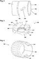
- Fig. 5 shows the drive tube 260 having a proximal-most circumferential flange 261, a proximal array of circumferential splines 262 and a distal array of circumferential splines 263.
- the flange is adapted to engage release button snap members 291
- the proximal splines are adapted to engage the transmission member splines 242 to provide a release coupling
- the distal splines are coupling splines adapted to axially engage the piston driver 230 during actuation to provide a drive coupling.
- the drive tube further comprises a proximal narrow-diameter portion with an axial slot 267 for attaching the inner end of the drive spring, as well as a distal larger-diameter portion with a number of outer spline ridges 265 adapted to interface with a scale drum.
- a proximal narrow-diameter portion with an axial slot 267 for attaching the inner end of the drive spring, as well as a distal larger-diameter portion with a number of outer spline ridges 265 adapted to interface with a scale drum.
- one of the splines is different allowing it to rotationally mate with a corresponding scale drum spline.
- the housing member proximal portion, the dose setting member, the transmission member and the release button are shown in an assembled state.
- the figure further shows the scale drum 270 provided with an inner longitudinal spline 271 for engagement with the drive tube and an outer helical groove 272 for threaded connection with the housing inner surface.
- the drive tube and the torsion spring have been omitted in fig. 6 .
- the dose setting member 280 is mounted rotationally free but axially locked on the housing member by means of the flanges arranged in the circumferential housing groove 208.
- the transmission member 240 is mounted non-rotationally on the drive tube (see fig. 7 ) by means of a splined connection allowing the transmission member to move axially relative to both the drive tube and the dose setting member.
- the release button 290 is mounted rotationally free but axially locked to the proximal end of the drive tube by means of a number of snap members 291 engaging the drive tube proximal flange 261.
- the release button further comprises a number of leg portions 298 adapted to be moved through the transmission member openings 248.
- a bias means in form of a return spring 295 is arranged between the transmission member 240 and the release button, the return spring urging the transmission member ratchet teeth 243 into engagement with the housing member ratchet teeth 203 as shown.
- one of the drive-lift ratchet control structures 283 is arranged corresponding to a transmission member drive section, the two drive surfaces and the two lift surfaces engaging each other. As appears, in the engaged position the ratchet prevents the transmission member, and thus the drive tube, from being turned counter-clockwise.
- the dose setting member When setting a dose the dose setting member is rotated clockwise. As the drive surfaces 287 of the drive-lift ratchet control structures 283 are in engagement with the corresponding drive surfaces 247 on the transmission member the latter is forced to rotate together with the dose setting member to the desired rotational position, this resulting in the transmission member ratchet teeth passing over the housing ratchet teeth during which the transmission member is moved back and forth due to the inclined ratchet teeth, the return spring and the splined connection with the drive tube.
- the dose can be set in increments corresponding to one ratchet tooth which e.g. for a given insulin delivery device typically will correspond to one unit (IU) of insulin formulation.
- the drive spring is strained correspondingly. To ensure a proper drive torque also for smaller doses the drive spring is pre-strained in the initial state.
- the dose setting member When decreasing a set dose the dose setting member is rotated counter-clockwise whereby a gap is created between the drive surfaces on the drive-lift ratchet control structure 283 respectively the transmission member.
- the inclined lift surfaces 286 of the drive-lift control structures are in engagement with the corresponding lift surfaces 246 on the transmission member the latter is moved proximally against the return spring until the transmission member ratchet teeth just disengages the housing ratchet teeth, at which point the force from the strained spring will rotate the drive tube counter-clockwise and thereby also the transmission member, this resulting in the inclined lift surfaces disengaging each other.
- the transmission member can be moved distally by the return spring whereby the ratchet teeth will re-engage, this corresponding to the previously set dose having been decreased by one increment. If the user continuous to rotate the dose setting member counter-clockwise the set dose will continue to be reduced by one increment for each back and forth movement of the transmission member. At the same time the scale drum is also rotated counter-clockwise and the dose size shown in the display window 202 is reduced correspondingly.
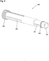
- the figure shows the device of fig. 6 with further components of the dose setting and expelling mechanism arranged inside the housing 201. More specifically, the figure shows a drive tube 260 in splined connection with the scale drum 270, a non-helical clock-type torsion drive spring 255 mounted in a cup-shaped spring housing 250 and connected to the spring housing respectively the drive tube, a threaded piston rod 220 arranged inside the drive tube and being threadedly connected to a stationary housing nut portion 207, a piston driver 230 arranged non-rotatable but axially moveable on the piston rod, as well as a drive coupling 263 allowing the drive tube to be coupled in and out of engagement with the piston driver.
- a drive tube 260 in splined connection with the scale drum 270
- a non-helical clock-type torsion drive spring 255 mounted in a cup-shaped spring housing 250 and connected to the spring housing respectively the drive tube
- a threaded piston rod 220 arranged inside the drive tube
- the spring housing comprises a number of oblong lateral projections 259 adapted to be slidingly received in the inclined housing slots 209, this allowing the spring housing and spring to be moved axially back and forth as the drive tube is moved back and forth during actuation, the inclined slots together with the spring torque ensuring that the spring housing and associated structures will be moved proximally when the device is not actuated.
- the spring housing is described in greater detail in EP 15165735.0 .
- the device further comprises an end-of-content member 225 in threaded engagement with the piston rod and in splined engagement with the drive tube via splines 228 received in corresponding axial grooves 268.
- the actuation button 290 is moved distally against the axial forces of the return spring and the drive spring whereby firstly the distal end of the drive tube 260 engages the piston driver 230 via the drive coupling 263 and secondly the drive tube splines of the release coupling disengages the transmission member splines 242, this allowing the strained spring 255 to rotate the drive tube and thereto coupled piston driver and piston rod 220 counter-clockwise, this resulting in the piston rod being moved distally through the threaded housing nut 207.
- the return spring and the drive spring serve to return the button and drive tube in the proximal direction and thereby firstly re-engage the splined connection between the drive tube and the transmission member and secondly dis-engage the drive tube from the piston driver, this movement also allowing a partly expelled dose to be paused.
- the drive mechanism disclosed in figs. 6 and 7 comprises a drive spring 255 and a scale drum 270 which both are arranged in the circumferential space between the drive tube 260 and the housing 201 but axially apart. Further, as the drive coupling is located at the distal end of the drive tube this allows the proximal portion of the piston rod 220 to be housed in the drive tube without additional components arranged between the piston rod and the drive tube inner surface, this providing a design with a smaller number of "layers" and thus a smaller diameter as would otherwise be the case.
- a compact expelling mechanism for a drug delivery device will be described.
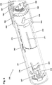
- the mechanism is similar to the mechanism described above with reference to figs. 2-7 and basically comprises a number of inner housing portions 301 arranged inside a common tubular sleeve 302 to provide a combined housing, a housing nut portion 307, a drive tube 360, a torsion drive spring 355 arranged between a housing portion and the drive tube, a scale drum 370 also arranged between a housing portion and the drive tube, a transmission member 340, a piston rod 320, a piston driver 330, and an end-of-content member 325.
- the scale drum 370 is arranged in the circumferential space between the drive tube 360 and the housing member 301, the scale drum being rotationally locked to the drive tube via longitudinal splines (not seen) and being in rotational threaded engagement with an inner helical thread 303 of the housing member via cooperating thread structures 373, whereby the helical row of numerals passes the display window opening 304 in the housing member when the drum is rotated relative to the housing by the drive tube.
- the spline connection comprises a number of ridge/tooth structures, typically two or three, in sliding engagement with corresponding grooves.
- the grooves may be formed in the scale drum inner surface and the ridge structures being formed on the drive tube outer surface, the ridge structures thereby having an axial position which does not move during dose setting.
- the grooves may be formed in the drive tube outer surface and the ridge structure being formed on the scale drum inner surface, the ridge structures thereby having an axial position which move axially during dose setting.
- the proximal-most of the ridge structures could be said to define the proximal-most axial position of the spline connection.
- the ridge structures are arranged at the same axial position just as ridge structures are arranged on either of the two splined members.
- the housing helical thread is arranged proximally of the display window 304.
- the scale drum may move proximally from an initial distal position during dose setting, or it may move distally from an initial proximal position during dose setting.
- the dose setting member is in the form of a combined dose setting and release member 380.
- a moveable spring housing is not provided, but the combined dose setting and release member 380 houses a dose logging unit 385 comprising electronic circuitry, a rotational sensor and a display, the logging unit being adapted to detect the size of set and/or expelled dose amounts.
- the display is covered by a proximal window 390 serving as a button surface for releasing the expelling mechanism.
- a proximal window 390 serving as a button surface for releasing the expelling mechanism.
- the transmission member 340 is located distally of the drive spring and as in the first embodiment it interacts with the housing to provide a two-way dose setting ratchet mechanism and the drive tube to provide a release coupling.
- the scale drum 370, the drive member 330, the drive coupling and the end-of-content member 325 are arranged similar to the first embodiment and generally works in the same way.
- the operation and working principles of the second embodiment are generally identical to the first embodiment, i.e. the user sets a dose to be expelled and strains the drive spring by rotating the a combined dose setting and release member 380, the drive tube and drive spring being held in their set rotational position by means of the release coupling. Subsequently the user moves the combined dose setting and release member 380 distally, this resulting in the drive coupling being activated and the release coupling subsequently released whereby the set dose of drug is expelled.
- the drive mechanism disclosed in fig. 8 comprises a drive spring 355 and a scale drum 370 which both are arranged in the circumferential space between the drive tube 360 and the housing 301, 302 but axially apart and thus non-overlapping with the scale drum in its proximal-most position.
- the drive coupling is located at the distal end of the drive tube this allows the proximal portion of the piston rod 320 to be housed in the drive tube without additional components arranged there between, this providing a design with a smaller number of "layers" and thus a smaller diameter as would otherwise be the case.
- a compact expelling mechanism for a drug delivery device will be described.
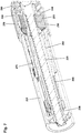
- the proximal not shown portion of the mechanism is similar to the mechanism described above with reference to fig. 8 , however, the distal portion of the mechanism comprising the drive coupling has been modified.
- the drug delivery device 400 comprises a number of inner housing portions 401 arranged inside a common tubular sleeve 402 to provide a combined housing, a housing nut portion 407, a drive tube 460, a scale drum 470 arranged between a housing portion and the drive tube, a spiral drive spring 455, a threaded piston rod 420, a piston driver 430, a coupling member 410, a coupling member spring 411 and a ratchet member 440.
- the device further comprises a coupling actuator 415, a cartridge holder member 416, a cartridge support 417, a cartridge support spring 418, a brake member 445 and an end-of-content member 435.
- the inner housing comprises a tubular inner housing portion 405 serving as an anchor structure for the outer end of the drive spring, a circumferential space 406 being defined between the inner housing and the tubular inner housing portion.
- the scale drum 470 is rotationally locked to the drive tube via longitudinal splines (not seen) and is in rotational threaded engagement with an inner helical thread 403 of the housing member via cooperating thread structures 473, whereby the helical row of numerals passes the display window opening 404 in the housing member when the drum is rotated relative to the housing by the drive tube.
- the scale drum 470 In the shown distal position the scale drum 470 is arranged in the circumferential space between the drive tube 460 and the housing member 401, whereas when it is moved proximally it is received in the circumferential housing space 406.
- the drive tube comprises a proximal narrow-diameter portion 468 adapted to receive the piston rod in its proximal position.
- the drive spring 455 is arranged in the circumferential space between the drive tube narrow-diameter proximal portion 468 and the tubular inner housing portion 405. As appears, when the scale drum 470 is in its distal-most position it is arranged distally of the drive spring 455, whereas the scale drum moves into an overlapping state with the drive spring as it is moved proximally during dose setting.
- the spline connection comprises a number of ridge/tooth structures, typically two or three, in sliding engagement with corresponding grooves.
- the grooves may be formed in the scale drum inner surface and the ridge structures being formed on the drive tube outer surface, the ridge structures thereby having an axial position which does not move during dose setting.
- the grooves may be formed in the drive tube outer surface and the ridge structure being formed on the scale drum inner surface, the ridge structures thereby having an axial position which move axially during dose setting.
- the proximal-most of the ridge structures could be said to define the proximal-most axial position of the spline connection.
- the ridge structures are arranged at the same axial position just as ridge structures are arranged on either of the two splined members.
- the housing helical thread 403 is arranged distally of the display window 404.
- the scale drum may move proximally from an initial distal position during dose setting, or it may move distally from an initial proximal position during dose setting.
- the scale drum 470 moves proximally from an initial distal position during dose setting
- the piston driver 430 is arranged non-rotatable but axially moveable on the piston rod.
- the piston driver 430 comprises a proximal tubular extension 431 on which the end-of-content member 435 is arranged in threaded engagement, the end-of-content member further being coupled to the drive tube 460 by splines, this providing that the end-of-content member is moved proximally during dose setting.
- the ratchet member 440 is coupled to the housing and allowed to rotate uni-directionally during out-dosing.
- the coupling member 410 is in splined connection with both the drive member 430 and the ratchet member 440, this providing that the drive member 430 is rotationally locked to the housing during dose setting.
- the ratchet member 440 is provided with inner proximal splines 441 adapted to receive drive tube distal outer splines 461, this providing an actuatable drive coupling.
- the ring-shaped brake member 445 is arranged between the housing and ratchet member 440. The working principle of the brake member is described in detail in WO 2015/055642 .
- the cartridge support spring 418 is arranged between the cartridge support 417 and the coupling actuator 415 and exerts a distally directed biasing force on the cartridge support 417.
- the coupling member spring 411 is arranged between the coupling member 410 and the drive member 430 and exerts a distally directed biasing force on the coupling member 410.
- the actuation button is moved distally against the axial forces of the return spring (as in the fig. 8 embodiment) whereby firstly the distal spline end 461 of the drive tube 460 engages the ratchet member proximal splines 441 and thereby, via the coupling member 410, the piston driver 430, and secondly the drive tube release coupling disengages (as in the fig. 8 embodiment), this allowing the strained spring to rotate the drive tube and thereto coupled piston driver and piston rod 420, this resulting in the piston rod being moved distally through the threaded housing nut 407.
- the return spring serve to return the button and drive tube in the proximal direction and thereby firstly re-engage the proximal release coupling and secondly dis-engage the drive tube 440 from the ratchet member 460 and thereby from the piston driver 430, this movement also allowing a partly expelled dose to be paused.
- the third embodiment is provided with a front-loaded cartridge holder comprising the shown rotatable cartridge holder member 416 which is coupled to the coupling actuator.
- the coupling actuator 415 is moved proximally whereby the coupling member 410 against the bias of the coupling member spring 411 is moved out of its splined engagement with the ratchet member 440, this allowing the coupling member, the drive member 430 and thereby the piston rod 420 to rotate, whereby the piston rod can be rotated proximally through the threaded nut portion 407, this allowing a new cartridge to be inserted in the cartridge holder.
- the coupling actuator 415 When the cartridge holder member 416 is rotated in the opposite direction to close the cartridge holder, the coupling actuator 415 is moved distally, this allowing the coupling member 410 to re-engage the ratchet member 440, the coupling member being biased distally by the coupling member spring 411.
- the drug delivery device described with reference to fig. 9 may be provided with a traditional rear-loaded cartridge holder, the coupling actuator 415 being actuated when the cartridge holder is de-coupled from the drive assembly portion.
- the drive spring is not arranged corresponding to the above-described embodiment.
- the mechanism basically comprises a housing member 501, a drive tube 560, a helical torsion spring 555 arranged between the housing and the drive tube, a transmission member 540, a drive-lift control member 590, a combined dose setting and release member 580 and a return spring 595.
- the main difference between the first and second embodiment is that the functionality of the dose setting member has been split into two members, this allowing the dose setting member to move axially relative to the housing. Otherwise the general working principles of the two embodiments are the same as will be apparent from the detailed description of the working principle given below, however, first some of the central components of the dose setting mechanism will be described in detail.
- a housing base member 501 defining a longitudinal reference axis is shown.
- the housing base member is attached to the proximal end of a tubular main housing member 509 (see fig. 14 ) and forms the base for a drive spring.
- the housing member comprises a proximally-facing conical surface on which a plurality of ratchet teeth structures 503 (here: 24) is arranged around a central opening, each tooth having a triangular configuration with an inclined ratchet surface 504 and a stop surface 505 oriented perpendicularly to the housing member cross-sectional plane.
- the housing base member further comprises an outer circumferential array of longitudinal splines 508 adapted to engage the dose setting member. In this way a first ratchet part coupled non-rotationally to the housing and comprising a plurality of ratchet teeth is formed. As appears, in this embodiment the first ratchet part is formed integrally with the housing base member.
- Fig. 11 shows the transmission member 540 having a ring-shaped body portion 541 with a central opening provided with a plurality of longitudinally arranged splines 542 adapted to slidingly engage corresponding spline grooves on the drive tube.
- the transmission member comprises a distally-facing (when mounted) concave surface on which a first plurality of ratchet teeth structures 543 (here: 24) is arranged around the central opening, each tooth having a triangular configuration with an inclined ratchet surface 544 and a stop surface 545 oriented perpendicularly to the housing member cross-sectional plane, the ratchet teeth being configured to interface with the corresponding ratchet teeth on the housing member to thereby provide a one-way ratchet.
- a first plurality of ratchet teeth structures 543 here: 24
- the transmission member further comprises an outer circumferential flange 549 with a second plurality (here: 24) of distally-facing (when mounted) ratchet teeth structures 548, each tooth having a configuration with an inclined lift surface 546 and a drive surface 547 oriented perpendicularly to the housing member cross-sectional plane.
- each tooth has a flat top.
- the drive-lift surfaces have been separated from the main ratchet structure.
- Fig. 12 shows the dose setting member 580 having a generally tubular configuration with an outer cylindrical surface with a plurality of longitudinally arranged ridges 581 providing a gripping surface, and an inner cylindrical surface comprising at the distal end a number of longitudinally arranged splines 588 adapted to interface with the housing member splines 508.
- the dose setting member further comprises an inner ring-formed transversal partition wall 585 with a central opening 586 adapted to rotationally interface with the drive tube proximal end.
- the drive-lift member 590 is configured as a ring-formed member having an outer circumferential surface with a plurality of longitudinally arranged splines 598 adapted to interface with the dose setting member splines 588, as well as a plurality of proximally-facing drive-lift teeth 599 arranged on the proximal circumferential edge, each tooth having a triangular form with a longitudinally oriented drive surface 597 and an inclined lift surface 596 adapted to engage the corresponding drive-lift surfaces 547, 546 on the transmission member 540.
- Fig. 14 shows a tubular main housing 509 to which the housing base member 501 is attached, the drive-lift control member 590, the drive tube 560 and a thereon mounted ball bearing 565, a helical drive spring 555 arranged around a portion of the drive tube and being connected to the spring base housing member 501 respectively the drive tube, a threaded piston rod 520 arranged inside the drive tube 560 and a scale drum 570 in threaded engagement with the housing main.
- the transmission member 540, the dose setting member 580 and the return spring 595 have been mounted.
- the distal portion of the device comprises a piston drive member and a drive coupling arrangement (not shown).
- the dose setting member 580 is mounted axially moveable relative to the housing member 501 between a proximal position (as shown in fig. 15 ) in which the splines 588 engages the splines 598 on the drive-lift control member 590, this allowing the dose setting member to rotate during dose setting, and a distal position in which the splines 588 engages the splines 508 on the housing member, this rotationally locking the dose setting member to the housing member.
- the dose setting member remains in splined connection with control member.
- the dose setting member is mounted axially locked but rotationally free on the drive tube proximal end by means of a ball bearing 565, this allowing the dose setting member to serve as a combined dose setting and actuation member as will be described below.
- the proximal open end of the dose setting member is closed by a circular plate (not shown).
- the transmission member 540 is mounted non-rotationally on the drive tube by means of a splined connection 542, 562 allowing the transmission member to move axially relative to both the drive tube and the dose setting member.
- a bias means in the form of a return spring 595 is arranged between the transmission member and the dose setting member partition wall 585, the return spring urging the transmission member ratchet teeth 543 into engagement with the housing member ratchet teeth 503 as shown.
- the ratchet prevents the transmission member, and thus the drive tube, from being turned counter-clockwise.
- the drive-lift control member 590 is during dose setting rotationally locked to the dose setting member via the splined connection, and the drive-lift teeth of the drive-lift member and the transmission member are urged into engagement by the return spring.
- the dose setting member in its proximal position is rotated clockwise.
- the drive surfaces 597 of the drive-lift control member 590 are in engagement with the corresponding drive surfaces 547 on the transmission member 540 the latter is forced to rotate together with the dose setting member to the desired rotational position, this resulting in the transmission member ratchet teeth 543 passing over the housing member ratchet teeth 503 during which the transmission member is moved back and forth due to the inclined ratchet teeth, the return spring 595 and the splined connection with the drive tube.
- the dose can be set in increments corresponding to one ratchet tooth which e.g. for a given insulin delivery device typically will correspond to one unit (IU) of insulin formulation.
- the dose setting member When decreasing a set dose the dose setting member is rotated counter-clockwise whereby a gap is created between the drive surfaces on the drive-lift control member 590 respectively the transmission member 540.
- the inclined lift surfaces 596 of the drive-lift control member are in engagement with the corresponding lift surfaces 546 on the transmission member the latter is moved proximally against the return spring until the transmission member ratchet teeth just disengages the housing member ratchet teeth, at which point the force from the strained drive spring 555 will rotate the drive tube counter-clockwise and thereby also the transmission member, this resulting in the inclined lift surfaces disengaging each other.
- the transmission member can be moved distally by the return spring whereby the ratchet teeth will re-engage, this corresponding to the previously set dose having been decreased by one increment. If the user continuous to rotate the dose setting member counter-clockwise the set dose will continue to be reduced by one increment for each back and forth movement of the transmission member. At the same time the scale drum is also rotated counter-clockwise and the dose size shown in the display window is reduced correspondingly.
- the combined dose setting and actuation member 580 is moved distally against the force of the return spring 595 whereby at first the dose setting member connects to the splines 508 of the housing spring base member 501 to prevent further adjustment of the set dose, secondly the distal end of the drive tube 560 engages the piston driver via the drive coupling, and thirdly the drive tube splines disengages the transmission member splines 542, this allowing the strained spring 555 to rotate the drive tube and thereto coupled piston driver and piston rod 520 counter-clockwise, this resulting in the piston rod being moved distally through a threaded housing nut.
- the return spring serves to return the member and drive tube in the proximal direction and thereby firstly re-engage the splined connection between the drive tube and the transmission member and secondly dis-engage the drive tube from the piston driver, this movement also allowing a partly expelled dose to be paused.
- the drive-lift teeth structures on the ratchet member 540 respectively the control member 590 may be configured corresponding to two alternatives, either with “non-inclined” drive surfaces corresponding to the embodiments described with reference to figs. 10-15 or, alternatively, with “inclined” drive surfaces to provide an over-torque protection mechanism during dial-up, this as described in greater in EP16186501.9 .
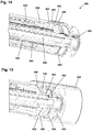
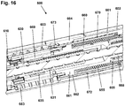
- fig. 16 shows the central portion of a drive mechanism embodying a compact arrangement of a housing member, a drive tube, a drive member, a piston rod and a drive spring. The figure does not show the distal and proximal portions of the drug delivery device as these are not considered relevant for the described aspect of the invention.
- the drug delivery device 600 comprises an inner housing 601 arranged inside a tubular sleeve 602 to provide a combined housing, a drive tube 660, a scale drum 670 arranged between a housing portion and the drive tube, a drive spring 655, a threaded piston rod 620, a driver 630 and a coupling member 610.
- the inner housing comprises a tubular inner housing portion 605 serving as a proximal stop for the drive tube as well as an anchor structure for the proximal end of the drive spring.
- the scale drum 670 is arranged in the circumferential space between the drive tube 660 and the housing member 601, the scale drum being rotationally locked to the drive tube via longitudinal splines 662, 672 and being in rotational threaded engagement with an inner helical thread 603 of the housing member via cooperating thread structures 673, whereby the helical row of numerals passes the display window opening 604 in the housing member when the drum is rotated relative to the housing by the drive tube.
- the drive tube is functionally a single member, however, in the shown embodiment it comprises for manufacturing purposes a longer inner tubular member 660 and a shorter outer tubular skirt member 669 coupled to each other to provide a rotationally and axially locked connection.
- the skirt member 669 comprises at the distal end an inner array of axially oriented distally facing splines 663 adapted to engage corresponding spline structures on the coupling member 610 in the expelling state.
- the drive tube comprises approximately in the middle a central circumferential flange 661.
- the drive tube comprises a proximal narrow-diameter portion 668 adapted to receive the piston rod in its proximal position.
- the spline connection comprises a number of ridge/tooth structures (here: two) in sliding engagement with corresponding grooves.
- the grooves 672 are formed in the scale drum inner surface and the ridge structures 662 being formed on the drive tube outer surface, the ridge structures thereby having an axial position which does not move during dose setting.
- the proximal-most of the ridge structures could be said to define the proximal-most axial position of the spline connection, however, in the shown embodiment the ridge structures are arranged at the same axial position.
- the housing helical thread 603 is arranged distally of the display window 604.
- the scale drum may move proximally from an initial distal position during dose setting, or it may move distally from an initial proximal position during dose setting.
- the scale drum is position in an initial proximal position.
- the drive spring 655 is in the form of a helical open wound torsion spring with a distal hook portion for attachment to the drive tube corresponding to the central flange 661 and a proximal hook portion for attachment to the housing member corresponding to the inner tubular portion 605.
- the drive spring is pre-wound to provide a desirable initial torque.
- the drive spring is arranged just proximally of the spline ridge structures. With the scale drum 670 in the proximal-most position the drive spring is housed in the circumferential space between the drive tube 660 and the scale drum 670 whereas with the scale drum in its distal-most position the drive spring faces the inner housing.
- the driver 630 is in engagement with the piston rod 620 via a pair of opposed splines, the piston rod and the driver thereby rotating together when the driver via the coupling member 610 is rotated by the drive tube during dose expelling.
- the driver 630 comprises a proximal tubular extension 631 on which the end-of-content member 635 is arranged in threaded engagement, the end-of-content member further being coupled to the drive tube 660 by splines, this providing that the end-of-content member is moved proximally during dose setting.
Claims (13)
- Dispositif d'administration de médicament (600) comprenant ou adapté pour recevoir une cartouche remplie de médicament, comprenant :- un logement (601),- un assemblage d'expulsion comprenant :- une tige de piston (620) adaptée pour engager et déplacer axialement un piston dans une cartouche chargée dans une direction distale pour ainsi expulser une dose de médicament de la cartouche, la tige de piston ayant une position la plus proximale,- une structure d'entraînement (660) logeant au moins partiellement la tige de piston,- un élément d'entraînement (630) agencé en engagement avec la tige de piston et adapté pour faire tourner la tige de piston,- un ressort d'entraînement hélicoïdal (655) agencé en engagement avec le logement et la structure d'entrainement,- des moyens de réglage (280, 380) permettant à un utilisateur de régler simultanément une quantité de dose à expulser et de tendre le ressort d'entraînement de manière correspondante par rotation de la structure d'entraînement,- un tambour gradué (670) couplé de manière hélicoïdale au logement ainsi que mobile axialement mais couplé de manière non rotative à la structure d'entraînement, le tambour gradué étant ainsi déplacé de manière hélicoïdale lors de la rotation de la structure d'entraînement,- des moyens de couplage (610, 663) pouvant être actionnés entre un état de réglage de dose dans lequel la structure d'entraînement peut être tournée vers une position définie, et un état d'expulsion dans lequel la structure d'entraînement entraînée par le ressort d'entraînement peut faire tourner l'élément d'entraînement, et- des moyens de libération (290, 390) pouvant être actionnés entre un état de réglage de dose et un état d'expulsion pour ainsi actionner les moyens de couplage,- dans lequel le ressort d'entraînement peut être libéré pour faire tourner la structure d'entraînement et ainsi l'élément d'entraînement pour ainsi faire tourner et déplacer la tige de piston dans la direction distale,
caractérisé en ce que
la structure d'entrainement est sous la forme d'un tube d'entraînement,- dans lequel le tambour gradué est couplé au tube d'entraînement via une connexion cannelée (265, 261, 662, 672), la connexion cannelée durant le réglage de la dose ayant une position la plus proximale correspondant à une position proximale la plus proximale du tambour gradué,- dans lequel le ressort d'entraînement est agencé à proximité de la connexion cannelée lorsque la connexion cannelée est dans sa position la plus proximale, et- dans lequel le ressort d'entraînement avec le tambour gradué dans sa position la plus proximale est agencé au moins partiellement entre le tambour gradué et le tube d'entraînement. - Dispositif d'administration de médicament selon la revendication 1, dans lequel la connexion cannelée comprend une structure de crête la plus proximale (662) en engagement coulissant avec une rainure correspondante (672), la rainure étant formée dans la surface intérieure du tambour gradué et la structure de crête la plus proximale étant formée sur la surface externe du tube d'entraînement,- où la structure de crête la plus proximale, et ainsi la connexion cannelée, a une position axiale qui ne se déplace pas durant le réglage de dose.
- Dispositif d'administration de médicament selon la revendication 1, dans lequel la connexion cannelée comprend une structure de crête la plus proximale dans l'engagement coulissant avec une rainure correspondante, la rainure étant formée dans la surface externe du tube d'entraînement et la structure de crête la plus proximale étant formée sur la surface interne du tambour gradué,- où la structure de crête la plus proximale, et ainsi la connexion cannelée, a une position axiale qui se déplace durant le réglage de dose.
- Dispositif d'administration de médicament selon l'une quelconque des revendications 1-3, dans lequel les moyens de libération comprennent un élément de libération (290, 390) mobile axialement entre une position de réglage de dose proximale et une position d'expulsion de dose distale actionnée.
- Dispositif d'administration de médicament selon l'une quelconque des revendications 1-4, dans lequel les moyens de réglage comprennent un élément de réglage de dose rotatif (280, 380) et les moyens de couplage comprennent :- un premier agencement de couplage (242, 262) pouvant être actionné entre un état de réglage de dose dans lequel l'élément de réglage est verrouillé de manière rotative sur le tube d'entraînement et dans lequel le tube d'entraînement peut être maintenu dans une position définie contre la force de sollicitation du ressort d'entraînement contraint, et un état d'expulsion dans lequel le tube d'entraînement est découplé de manière rotative de l'élément de réglage de dose et peut être mis en rotation par le ressort d'entraînement, et- un deuxième agencement de couplage (410) pouvant est actionné entre un état de réglage de dose dans lequel le tube d'entraînement peut tourner par rapport à l'élément d'entraînement et un état d'expulsion dans lequel le tube d'entraînement est verrouillé de manière rotative à l'élément d'entrainement,
dans lequel les moyens de libération, lorsqu'ils sont actionnés, actionnent le premier agencement de couplage de l'état de réglage de dose à l'état d'expulsion, et actionne le deuxième agencement de couplage de l'état de réglage de dose à l'état d'expulsion. - Dispositif d'administration de médicament selon la revendication 5, dans lequel l'élément de réglage de dose (380) est couplé et se déplace axialement avec l'élément de libération.
- Dispositif d'administration de médicament selon la revendication 6, dans lequel l'élément de réglage de dose et l'élément de libération sont formés par un élément ou un ensemble combiné de réglage et de libération de dose (380, 390).
- Dispositif d'administration de médicament selon l'une quelconque des revendications 1-7, les moyens de couplage comprenant un mécanisme à cliquet permettant au tube d'entraînement d'être maintenu dans une position définie contre la force de sollicitation du ressort d'entraînement tendu.
- Dispositif d'administration de médicament selon la revendication 8, dans lequel le mécanisme de cliquet est sous la forme d'un mécanisme à cliquet unidirectionnel libérable permettant de réduire une dose définie, le mécanisme à cliquet étant associé soit au premier soit au deuxième agencement de couplage.
- Dispositif d'administration de médicament selon la revendication 9, dans lequel le mécanisme à cliquet comprend :- une première partie de cliquet (201, 501) comprenant une pluralité de dents de cliquet (203, 503), la première partie de cliquet étant couplée de manière non rotative au logement durant le réglage de dose,- une deuxième partie de cliquet (240, 540) comprenant une pluralité de dents de cliquet (243, 543) adaptées pour engager de manière rotative les dents de cliquet sur la première partie de cliquet, la deuxième partie de cliquet étant couplée de manière non rotative à l'élément d'entraînement durant le réglage de dose, les première et deuxième parties de cliquet étant mobiles axialement l'une par rapport à l'autre durant le réglage de dose,- des moyens de sollicitation (295, 595) pour la sollicitation axialement des première et deuxième parties de cliquet en engagement l'une avec l'autre, et- des moyens de commande adaptés pour faire tourner la deuxième partie de cliquet dans la première direction afin de régler ainsi une dose lorsque l'élément de réglage de dose est tourné dans la première direction, et de déplacer les première et deuxième parties de cliquet axialement hors d'engagement l'une avec l'autre lorsque l'élément de réglage de dose est tourné dans la deuxième direction.
- Dispositif d'administration de médicament selon la revendication 10, dans lequel les moyens de commande comprennent :- un cliquet de libération d'entraînement (240, 540) ayant une pluralité de surfaces d'entraînement de cliquet (247, 547) et une pluralité de surfaces de libération de cliquet (246, 546) inclinées par rapport à un plan de référence rotatif, et- un cliquet de commande (283, 590) comprenant une pluralité de surfaces d'entrainement de commande (287, 597) et une pluralité de surfaces de libération de commande (286, 596) inclinées par rapport au plan de référence rotatif,dans lequel :- les surfaces d'entraînement de commande (287, 597) coopèrent avec les surfaces d'entraînement de cliquet (247, 547) pour faire tourner la deuxième partie de cliquet dans la première direction lorsque l'élément de réglage de dose est tourné dans la première direction, et- les surfaces de libération de commande (286, 596) coopèrent de manière coulissante avec les surfaces de libération de cliquet (246, 546) pour déplacer axialement les première et deuxième parties de cliquet hors d'engagement axialement l'une par rapport à l'autre lorsque l'élément de réglage de dose est tourné dans la deuxième direction,
où, lorsque les première et deuxième parties de cliquet ont été désengagées axialement, le ressort d'entraînement fera tourner la deuxième partie de cliquet dans la deuxième direction pour ainsi réduire la dose réglée, les moyens de sollicitation déplaçant les première et deuxième parties de cliquet axialement en engagement l'une par rapport à l'autre, ceci résultant en la réduction de la dose définie correspondant à une dent du mécanisme à cliquet. - Dispositif d'administration de médicament selon l'une quelconque des revendications 1-11, dans lequel :- le tube d'entraînement (460) comprend une partie proximale et une partie distale, la partie proximale (468) ayant un diamètre inférieur, et- le ressort d'entraînement (455) est agencé en correspondance avec la partie proximale du tube d'entraînement.
- Dispositif d'administration de médicament selon la revendication 12, dans lequel :- l'ensemble d'expulsion comprend un élément de fin de contenu (435, 635) agencé dans l'espace circonférentiel entre la tige de piston et le tube d'entraînement correspondant à la partie distale, l'élément de fin de contenu étant mobile axialement entre une position distale et une position proximale par rapport à la tige de piston.
Applications Claiming Priority (2)
| Application Number | Priority Date | Filing Date | Title |
|---|---|---|---|
| EP15189050 | 2015-10-09 | ||
| PCT/EP2016/073999 WO2017060426A1 (fr) | 2015-10-09 | 2016-10-07 | Dispositif d'administration de médicament avec mécanisme d'entraînement mince |
Publications (2)
| Publication Number | Publication Date |
|---|---|
| EP3359227A1 EP3359227A1 (fr) | 2018-08-15 |
| EP3359227B1 true EP3359227B1 (fr) | 2020-08-05 |
Family
ID=54291167
Family Applications (1)
| Application Number | Title | Priority Date | Filing Date |
|---|---|---|---|
| EP16778034.5A Active EP3359227B1 (fr) | 2015-10-09 | 2016-10-07 | Dispositif d'administration de médicament avec mécanisme d'entraînement mince |
Country Status (5)
| Country | Link |
|---|---|
| US (1) | US11458251B2 (fr) |
| EP (1) | EP3359227B1 (fr) |
| JP (1) | JP6893507B2 (fr) |
| CN (1) | CN108136126B (fr) |
| WO (1) | WO2017060426A1 (fr) |
Families Citing this family (1)
| Publication number | Priority date | Publication date | Assignee | Title |
|---|---|---|---|---|
| PL414382A1 (pl) | 2015-10-15 | 2017-04-24 | Copernicus Spółka Z Ograniczoną Odpowiedzialnością | Mechanizm nastawczy, w szczególności do dozowania |
Family Cites Families (22)
| Publication number | Priority date | Publication date | Assignee | Title |
|---|---|---|---|---|
| US6899699B2 (en) | 2001-01-05 | 2005-05-31 | Novo Nordisk A/S | Automatic injection device with reset feature |
| GB0304822D0 (en) | 2003-03-03 | 2003-04-09 | Dca Internat Ltd | Improvements in and relating to a pen-type injector |
| US20060004297A1 (en) | 2004-07-02 | 2006-01-05 | Orr Joseph A | Lung model-based cardiopulmonary performance determination |
| ATE444090T1 (de) | 2004-10-21 | 2009-10-15 | Novo Nordisk As | Wählmechanismus für einen drehstift |
| DE102004063645A1 (de) * | 2004-12-31 | 2006-07-20 | Tecpharma Licensing Ag | Vorrichtung zur dosierten Verabreichung eines fluiden Produkts mit Entkopplung für einen Behältniswechsel |
| DE602006010396D1 (de) | 2005-07-27 | 2009-12-24 | Novo Nordisk As | Spritzenvorrichtung mit einem dosisbegrenzenden mechanismus und einem zusätzlichen sicherheitsmechanismus |
| DE602006020453D1 (de) | 2005-07-27 | 2011-04-14 | Novo Nordisk As | Dosismechanismus für ein injektionsgerät zur begrenzung einer dosiseinstellung entsprechend der verbleibenden arzneimenge |
| DE102005060929A1 (de) * | 2005-09-14 | 2007-03-15 | Tecpharma Licensing Ag | Injektionsvorrichtung mit Zweiwege-Rutschkupplung |
| EP3738626B1 (fr) | 2006-09-15 | 2022-08-10 | Ypsomed AG | Appareil d'injection a element d'extraction ameliore |
| DE102008011885A1 (de) * | 2008-02-29 | 2009-09-10 | Tecpharma Licensing Ag | Doppelfunktionsfeder |
| DE102008011881A1 (de) * | 2008-02-29 | 2009-09-10 | Tecpharma Licensing Ag | Leerschießgeschwindigkeitsbegrenzungsbremse |
| GB0918145D0 (en) * | 2009-10-16 | 2009-12-02 | Owen Mumford Ltd | Injector apparatus |
| WO2011133089A1 (fr) | 2010-04-19 | 2011-10-27 | Shl Group Ab | Dispositif de distribution de médicaments pour auto-administration |
| US9283325B2 (en) * | 2011-05-12 | 2016-03-15 | Shl Group Ab | Medicament delivery device with dose re-setting |
| MX2014013842A (es) * | 2012-05-31 | 2015-02-18 | Novo Nordisk As | Mecanismo de seleccion descendente para pluma giratoria ascendente. |
| EP2866861A1 (fr) | 2012-06-29 | 2015-05-06 | Novo Nordisk A/S | Dispositif d'injection à ressort |
| EP2692376B1 (fr) * | 2012-08-01 | 2019-04-03 | TecPharma Licensing AG | Dispositif d'injection avec échelle de dosage en forme d'hélice ou de spirale |
| CN104736188B (zh) | 2012-10-15 | 2017-09-01 | 诺和诺德股份有限公司 | 弹簧驱动的注射装置 |
| CN105120931A (zh) | 2013-04-19 | 2015-12-02 | 诺和诺德股份有限公司 | 具有紧凑动力单元的药物传输装置 |
| US20150088515A1 (en) * | 2013-09-25 | 2015-03-26 | Lenovo (Singapore) Pte. Ltd. | Primary speaker identification from audio and video data |
| JP6611708B2 (ja) | 2013-10-16 | 2019-11-27 | ノボ・ノルデイスク・エー/エス | ブレーキ機構を有する薬物送達デバイス |
| CN105722540B (zh) | 2013-11-21 | 2019-06-28 | 诺和诺德股份有限公司 | 具有空间有效设计的旋转传感器组件 |
-
2016
- 2016-10-07 EP EP16778034.5A patent/EP3359227B1/fr active Active
- 2016-10-07 US US15/766,581 patent/US11458251B2/en active Active
- 2016-10-07 CN CN201680058957.9A patent/CN108136126B/zh active Active
- 2016-10-07 JP JP2018517879A patent/JP6893507B2/ja active Active
- 2016-10-07 WO PCT/EP2016/073999 patent/WO2017060426A1/fr active Application Filing
Non-Patent Citations (1)
| Title |
|---|
| None * |
Also Published As
| Publication number | Publication date |
|---|---|
| US20180289895A1 (en) | 2018-10-11 |
| WO2017060426A1 (fr) | 2017-04-13 |
| CN108136126A (zh) | 2018-06-08 |
| CN108136126B (zh) | 2021-06-25 |
| EP3359227A1 (fr) | 2018-08-15 |
| JP6893507B2 (ja) | 2021-06-23 |
| JP2018530387A (ja) | 2018-10-18 |
| US11458251B2 (en) | 2022-10-04 |
Similar Documents
| Publication | Publication Date | Title |
|---|---|---|
| US20160114107A1 (en) | Frontloaded Drug Delivery Device with Actuated Cartridge Holder and Piston Rod Coupling | |
| EP2999501A1 (fr) | Dispositif d'administration de médicament avec un moyen de désactivation de l'activation d'un mécanisme d'expulsion | |
| US20210283338A1 (en) | Drug delivery device with over-torque protection mechanism | |
| US10080845B2 (en) | Drug delivery device with piston rod coupling | |
| EP3261689B1 (fr) | Dispositif d'administration de médicament avec mécanisme de réglage de dose | |
| US9956349B2 (en) | Frontloaded drug delivery device with dynamic axial stop feature | |
| EP3548117B1 (fr) | Dispositif d'administration de médicament avec fonction de ressort de torsion | |
| US20170274148A1 (en) | Drug delivery device with combined setting and release member | |
| EP3288613B1 (fr) | Dispositif d'administration de médicament avec mécanisme à ressort | |
| EP3359227B1 (fr) | Dispositif d'administration de médicament avec mécanisme d'entraînement mince | |
| CN110191734B (zh) | 具有旋转齿轮传动的驱动杆的驱动装置 |
Legal Events
| Date | Code | Title | Description |
|---|---|---|---|
| STAA | Information on the status of an ep patent application or granted ep patent |
Free format text: STATUS: UNKNOWN |
|
| STAA | Information on the status of an ep patent application or granted ep patent |
Free format text: STATUS: THE INTERNATIONAL PUBLICATION HAS BEEN MADE |
|
| PUAI | Public reference made under article 153(3) epc to a published international application that has entered the european phase |
Free format text: ORIGINAL CODE: 0009012 |
|
| STAA | Information on the status of an ep patent application or granted ep patent |
Free format text: STATUS: REQUEST FOR EXAMINATION WAS MADE |
|
| 17P | Request for examination filed |
Effective date: 20180509 |
|
| AK | Designated contracting states |
Kind code of ref document: A1 Designated state(s): AL AT BE BG CH CY CZ DE DK EE ES FI FR GB GR HR HU IE IS IT LI LT LU LV MC MK MT NL NO PL PT RO RS SE SI SK SM TR |
|
| AX | Request for extension of the european patent |
Extension state: BA ME |
|
| DAV | Request for validation of the european patent (deleted) | ||
| DAX | Request for extension of the european patent (deleted) | ||
| STAA | Information on the status of an ep patent application or granted ep patent |
Free format text: STATUS: EXAMINATION IS IN PROGRESS |
|
| 17Q | First examination report despatched |
Effective date: 20190802 |
|
| GRAP | Despatch of communication of intention to grant a patent |
Free format text: ORIGINAL CODE: EPIDOSNIGR1 |
|
| STAA | Information on the status of an ep patent application or granted ep patent |
Free format text: STATUS: GRANT OF PATENT IS INTENDED |
|
| INTG | Intention to grant announced |
Effective date: 20200217 |
|
| GRAS | Grant fee paid |
Free format text: ORIGINAL CODE: EPIDOSNIGR3 |
|
| GRAA | (expected) grant |
Free format text: ORIGINAL CODE: 0009210 |
|
| STAA | Information on the status of an ep patent application or granted ep patent |
Free format text: STATUS: THE PATENT HAS BEEN GRANTED |
|
| AK | Designated contracting states |
Kind code of ref document: B1 Designated state(s): AL AT BE BG CH CY CZ DE DK EE ES FI FR GB GR HR HU IE IS IT LI LT LU LV MC MK MT NL NO PL PT RO RS SE SI SK SM TR |
|
| REG | Reference to a national code |
Ref country code: GB Ref legal event code: FG4D |
|
| REG | Reference to a national code |
Ref country code: CH Ref legal event code: EP |
|
| REG | Reference to a national code |
Ref country code: AT Ref legal event code: REF Ref document number: 1297828 Country of ref document: AT Kind code of ref document: T Effective date: 20200815 |
|
| REG | Reference to a national code |
Ref country code: DE Ref legal event code: R096 Ref document number: 602016041448 Country of ref document: DE |
|
| REG | Reference to a national code |
Ref country code: IE Ref legal event code: FG4D |
|
| REG | Reference to a national code |
Ref country code: LT Ref legal event code: MG4D |
|
| REG | Reference to a national code |
Ref country code: NL Ref legal event code: MP Effective date: 20200805 |
|
| REG | Reference to a national code |
Ref country code: AT Ref legal event code: MK05 Ref document number: 1297828 Country of ref document: AT Kind code of ref document: T Effective date: 20200805 |
|
| PG25 | Lapsed in a contracting state [announced via postgrant information from national office to epo] |
Ref country code: PT Free format text: LAPSE BECAUSE OF FAILURE TO SUBMIT A TRANSLATION OF THE DESCRIPTION OR TO PAY THE FEE WITHIN THE PRESCRIBED TIME-LIMIT Effective date: 20201207 Ref country code: BG Free format text: LAPSE BECAUSE OF FAILURE TO SUBMIT A TRANSLATION OF THE DESCRIPTION OR TO PAY THE FEE WITHIN THE PRESCRIBED TIME-LIMIT Effective date: 20201105 Ref country code: ES Free format text: LAPSE BECAUSE OF FAILURE TO SUBMIT A TRANSLATION OF THE DESCRIPTION OR TO PAY THE FEE WITHIN THE PRESCRIBED TIME-LIMIT Effective date: 20200805 Ref country code: LT Free format text: LAPSE BECAUSE OF FAILURE TO SUBMIT A TRANSLATION OF THE DESCRIPTION OR TO PAY THE FEE WITHIN THE PRESCRIBED TIME-LIMIT Effective date: 20200805 Ref country code: HR Free format text: LAPSE BECAUSE OF FAILURE TO SUBMIT A TRANSLATION OF THE DESCRIPTION OR TO PAY THE FEE WITHIN THE PRESCRIBED TIME-LIMIT Effective date: 20200805 Ref country code: SE Free format text: LAPSE BECAUSE OF FAILURE TO SUBMIT A TRANSLATION OF THE DESCRIPTION OR TO PAY THE FEE WITHIN THE PRESCRIBED TIME-LIMIT Effective date: 20200805 Ref country code: NO Free format text: LAPSE BECAUSE OF FAILURE TO SUBMIT A TRANSLATION OF THE DESCRIPTION OR TO PAY THE FEE WITHIN THE PRESCRIBED TIME-LIMIT Effective date: 20201105 Ref country code: AT Free format text: LAPSE BECAUSE OF FAILURE TO SUBMIT A TRANSLATION OF THE DESCRIPTION OR TO PAY THE FEE WITHIN THE PRESCRIBED TIME-LIMIT Effective date: 20200805 Ref country code: FI Free format text: LAPSE BECAUSE OF FAILURE TO SUBMIT A TRANSLATION OF THE DESCRIPTION OR TO PAY THE FEE WITHIN THE PRESCRIBED TIME-LIMIT Effective date: 20200805 Ref country code: GR Free format text: LAPSE BECAUSE OF FAILURE TO SUBMIT A TRANSLATION OF THE DESCRIPTION OR TO PAY THE FEE WITHIN THE PRESCRIBED TIME-LIMIT Effective date: 20201106 |
|
| PG25 | Lapsed in a contracting state [announced via postgrant information from national office to epo] |
Ref country code: RS Free format text: LAPSE BECAUSE OF FAILURE TO SUBMIT A TRANSLATION OF THE DESCRIPTION OR TO PAY THE FEE WITHIN THE PRESCRIBED TIME-LIMIT Effective date: 20200805 Ref country code: LV Free format text: LAPSE BECAUSE OF FAILURE TO SUBMIT A TRANSLATION OF THE DESCRIPTION OR TO PAY THE FEE WITHIN THE PRESCRIBED TIME-LIMIT Effective date: 20200805 Ref country code: NL Free format text: LAPSE BECAUSE OF FAILURE TO SUBMIT A TRANSLATION OF THE DESCRIPTION OR TO PAY THE FEE WITHIN THE PRESCRIBED TIME-LIMIT Effective date: 20200805 Ref country code: PL Free format text: LAPSE BECAUSE OF FAILURE TO SUBMIT A TRANSLATION OF THE DESCRIPTION OR TO PAY THE FEE WITHIN THE PRESCRIBED TIME-LIMIT Effective date: 20200805 Ref country code: IS Free format text: LAPSE BECAUSE OF FAILURE TO SUBMIT A TRANSLATION OF THE DESCRIPTION OR TO PAY THE FEE WITHIN THE PRESCRIBED TIME-LIMIT Effective date: 20201205 |
|
| PG25 | Lapsed in a contracting state [announced via postgrant information from national office to epo] |
Ref country code: RO Free format text: LAPSE BECAUSE OF FAILURE TO SUBMIT A TRANSLATION OF THE DESCRIPTION OR TO PAY THE FEE WITHIN THE PRESCRIBED TIME-LIMIT Effective date: 20200805 Ref country code: DK Free format text: LAPSE BECAUSE OF FAILURE TO SUBMIT A TRANSLATION OF THE DESCRIPTION OR TO PAY THE FEE WITHIN THE PRESCRIBED TIME-LIMIT Effective date: 20200805 Ref country code: CZ Free format text: LAPSE BECAUSE OF FAILURE TO SUBMIT A TRANSLATION OF THE DESCRIPTION OR TO PAY THE FEE WITHIN THE PRESCRIBED TIME-LIMIT Effective date: 20200805 Ref country code: EE Free format text: LAPSE BECAUSE OF FAILURE TO SUBMIT A TRANSLATION OF THE DESCRIPTION OR TO PAY THE FEE WITHIN THE PRESCRIBED TIME-LIMIT Effective date: 20200805 Ref country code: SM Free format text: LAPSE BECAUSE OF FAILURE TO SUBMIT A TRANSLATION OF THE DESCRIPTION OR TO PAY THE FEE WITHIN THE PRESCRIBED TIME-LIMIT Effective date: 20200805 |
|
| REG | Reference to a national code |
Ref country code: DE Ref legal event code: R097 Ref document number: 602016041448 Country of ref document: DE |
|
| PG25 | Lapsed in a contracting state [announced via postgrant information from national office to epo] |
Ref country code: AL Free format text: LAPSE BECAUSE OF FAILURE TO SUBMIT A TRANSLATION OF THE DESCRIPTION OR TO PAY THE FEE WITHIN THE PRESCRIBED TIME-LIMIT Effective date: 20200805 |
|
| PLBE | No opposition filed within time limit |
Free format text: ORIGINAL CODE: 0009261 |
|
| STAA | Information on the status of an ep patent application or granted ep patent |
Free format text: STATUS: NO OPPOSITION FILED WITHIN TIME LIMIT |
|
| PG25 | Lapsed in a contracting state [announced via postgrant information from national office to epo] |
Ref country code: LU Free format text: LAPSE BECAUSE OF NON-PAYMENT OF DUE FEES Effective date: 20201007 Ref country code: MC Free format text: LAPSE BECAUSE OF FAILURE TO SUBMIT A TRANSLATION OF THE DESCRIPTION OR TO PAY THE FEE WITHIN THE PRESCRIBED TIME-LIMIT Effective date: 20200805 Ref country code: SK Free format text: LAPSE BECAUSE OF FAILURE TO SUBMIT A TRANSLATION OF THE DESCRIPTION OR TO PAY THE FEE WITHIN THE PRESCRIBED TIME-LIMIT Effective date: 20200805 |
|
| 26N | No opposition filed |
Effective date: 20210507 |
|
| REG | Reference to a national code |
Ref country code: BE Ref legal event code: MM Effective date: 20201031 |
|
| PG25 | Lapsed in a contracting state [announced via postgrant information from national office to epo] |
Ref country code: IT Free format text: LAPSE BECAUSE OF FAILURE TO SUBMIT A TRANSLATION OF THE DESCRIPTION OR TO PAY THE FEE WITHIN THE PRESCRIBED TIME-LIMIT Effective date: 20200805 |
|
| PG25 | Lapsed in a contracting state [announced via postgrant information from national office to epo] |
Ref country code: BE Free format text: LAPSE BECAUSE OF NON-PAYMENT OF DUE FEES Effective date: 20201031 Ref country code: SI Free format text: LAPSE BECAUSE OF FAILURE TO SUBMIT A TRANSLATION OF THE DESCRIPTION OR TO PAY THE FEE WITHIN THE PRESCRIBED TIME-LIMIT Effective date: 20200805 |
|
| PG25 | Lapsed in a contracting state [announced via postgrant information from national office to epo] |
Ref country code: IE Free format text: LAPSE BECAUSE OF NON-PAYMENT OF DUE FEES Effective date: 20201007 |
|
| PG25 | Lapsed in a contracting state [announced via postgrant information from national office to epo] |
Ref country code: TR Free format text: LAPSE BECAUSE OF FAILURE TO SUBMIT A TRANSLATION OF THE DESCRIPTION OR TO PAY THE FEE WITHIN THE PRESCRIBED TIME-LIMIT Effective date: 20200805 Ref country code: MT Free format text: LAPSE BECAUSE OF FAILURE TO SUBMIT A TRANSLATION OF THE DESCRIPTION OR TO PAY THE FEE WITHIN THE PRESCRIBED TIME-LIMIT Effective date: 20200805 Ref country code: CY Free format text: LAPSE BECAUSE OF FAILURE TO SUBMIT A TRANSLATION OF THE DESCRIPTION OR TO PAY THE FEE WITHIN THE PRESCRIBED TIME-LIMIT Effective date: 20200805 |
|
| PG25 | Lapsed in a contracting state [announced via postgrant information from national office to epo] |
Ref country code: MK Free format text: LAPSE BECAUSE OF FAILURE TO SUBMIT A TRANSLATION OF THE DESCRIPTION OR TO PAY THE FEE WITHIN THE PRESCRIBED TIME-LIMIT Effective date: 20200805 |
|
| PGFP | Annual fee paid to national office [announced via postgrant information from national office to epo] |
Ref country code: GB Payment date: 20230920 Year of fee payment: 8 |
|
| PGFP | Annual fee paid to national office [announced via postgrant information from national office to epo] |
Ref country code: FR Payment date: 20230920 Year of fee payment: 8 |
|
| PGFP | Annual fee paid to national office [announced via postgrant information from national office to epo] |
Ref country code: DE Payment date: 20230920 Year of fee payment: 8 Ref country code: CH Payment date: 20231102 Year of fee payment: 8 |