EP3359226B1 - Infusionsvorrichtung zur verabreichung einer medizinischen flüssigkeit an einen patienten und verfahren zum betrieb einer infusionsvorrichtung - Google Patents
Infusionsvorrichtung zur verabreichung einer medizinischen flüssigkeit an einen patienten und verfahren zum betrieb einer infusionsvorrichtung Download PDFInfo
- Publication number
- EP3359226B1 EP3359226B1 EP16774680.9A EP16774680A EP3359226B1 EP 3359226 B1 EP3359226 B1 EP 3359226B1 EP 16774680 A EP16774680 A EP 16774680A EP 3359226 B1 EP3359226 B1 EP 3359226B1
- Authority
- EP
- European Patent Office
- Prior art keywords
- driving rod
- drive element
- state
- infusion
- clutching
- Prior art date
- Legal status (The legal status is an assumption and is not a legal conclusion. Google has not performed a legal analysis and makes no representation as to the accuracy of the status listed.)
- Active
Links
Images


Classifications
-
- A—HUMAN NECESSITIES
- A61—MEDICAL OR VETERINARY SCIENCE; HYGIENE
- A61M—DEVICES FOR INTRODUCING MEDIA INTO, OR ONTO, THE BODY; DEVICES FOR TRANSDUCING BODY MEDIA OR FOR TAKING MEDIA FROM THE BODY; DEVICES FOR PRODUCING OR ENDING SLEEP OR STUPOR
- A61M5/00—Devices for bringing media into the body in a subcutaneous, intra-vascular or intramuscular way; Accessories therefor, e.g. filling or cleaning devices, arm-rests
- A61M5/14—Infusion devices, e.g. infusing by gravity; Blood infusion; Accessories therefor
- A61M5/142—Pressure infusion, e.g. using pumps
- A61M5/14212—Pumping with an aspiration and an expulsion action
- A61M5/14216—Reciprocating piston type
-
- A—HUMAN NECESSITIES
- A61—MEDICAL OR VETERINARY SCIENCE; HYGIENE
- A61M—DEVICES FOR INTRODUCING MEDIA INTO, OR ONTO, THE BODY; DEVICES FOR TRANSDUCING BODY MEDIA OR FOR TAKING MEDIA FROM THE BODY; DEVICES FOR PRODUCING OR ENDING SLEEP OR STUPOR
- A61M5/00—Devices for bringing media into the body in a subcutaneous, intra-vascular or intramuscular way; Accessories therefor, e.g. filling or cleaning devices, arm-rests
- A61M5/14—Infusion devices, e.g. infusing by gravity; Blood infusion; Accessories therefor
- A61M5/142—Pressure infusion, e.g. using pumps
- A61M5/145—Pressure infusion, e.g. using pumps using pressurised reservoirs, e.g. pressurised by means of pistons
- A61M5/1452—Pressure infusion, e.g. using pumps using pressurised reservoirs, e.g. pressurised by means of pistons pressurised by means of pistons
- A61M5/14546—Front-loading type injectors
-
- A—HUMAN NECESSITIES
- A61—MEDICAL OR VETERINARY SCIENCE; HYGIENE
- A61M—DEVICES FOR INTRODUCING MEDIA INTO, OR ONTO, THE BODY; DEVICES FOR TRANSDUCING BODY MEDIA OR FOR TAKING MEDIA FROM THE BODY; DEVICES FOR PRODUCING OR ENDING SLEEP OR STUPOR
- A61M5/00—Devices for bringing media into the body in a subcutaneous, intra-vascular or intramuscular way; Accessories therefor, e.g. filling or cleaning devices, arm-rests
- A61M5/14—Infusion devices, e.g. infusing by gravity; Blood infusion; Accessories therefor
- A61M5/142—Pressure infusion, e.g. using pumps
- A61M5/145—Pressure infusion, e.g. using pumps using pressurised reservoirs, e.g. pressurised by means of pistons
- A61M5/1452—Pressure infusion, e.g. using pumps using pressurised reservoirs, e.g. pressurised by means of pistons pressurised by means of pistons
- A61M5/1456—Pressure infusion, e.g. using pumps using pressurised reservoirs, e.g. pressurised by means of pistons pressurised by means of pistons with a replaceable reservoir comprising a piston rod to be moved into the reservoir, e.g. the piston rod is part of the removable reservoir
-
- A—HUMAN NECESSITIES
- A61—MEDICAL OR VETERINARY SCIENCE; HYGIENE
- A61M—DEVICES FOR INTRODUCING MEDIA INTO, OR ONTO, THE BODY; DEVICES FOR TRANSDUCING BODY MEDIA OR FOR TAKING MEDIA FROM THE BODY; DEVICES FOR PRODUCING OR ENDING SLEEP OR STUPOR
- A61M5/00—Devices for bringing media into the body in a subcutaneous, intra-vascular or intramuscular way; Accessories therefor, e.g. filling or cleaning devices, arm-rests
- A61M5/178—Syringes
- A61M5/20—Automatic syringes, e.g. with automatically actuated piston rod, with automatic needle injection, filling automatically
Definitions
- the invention relates to an infusion device for administering a medical fluid to a patient according to the preamble of claim 1 and to a method for bringing an infusion device into an operative state.
- An infusion device of this kind comprises a housing, a receptacle arranged on the housing for receiving a syringe, and a pusher device movable in a pushing direction for acting onto a piston of a syringe received on the receptacle.
- the infusion device is constituted as a syringe pump, the syringe containing a medical fluid to be infused to a patient.
- a medical fluid of this kind may for example be a medication, a solution for the parenteral feeding or another medical solution which shall be infused to a patient.
- the pusher device is driven by a drive mechanism comprising a drive element connected to the pusher device.
- the drive element is longitudinally movable relative to the housing for moving the pusher device along the pushing direction and is driven by a driving rod having a screw thread.
- the driving rod is rotatable about a rotational axis and is in connection with an electric drive device serving to electrically rotating the driving rod.
- the drive element is in engagement with the screw thread of the driving rod in a releasable fashion.
- a clutching device is provided which is connected to the drive element and which is actuatable by an actuation device to engage, in a clutched state, with the screw thread of the driving rod for translating a rotational movement of the driving rod into a longitudinal movement of the drive element along the driving rod.
- the drive element is in operational connection with the driving rod such that the drive element is moved along the driving rod when the driving rod is rotated by means of the electric drive device.
- the clutching device can be brought into an unclutched state in which the clutching device is disengaged from the driving rod such that the drive element can be moved independently from the driving rod.
- the infusion device comprises a brake device constituted to act, in an activated state, onto the drive element for braking the drive element relative to the housing and to allow, in a deactivated state, a longitudinal movement of the drive element relative to the housing.
- the brake device By means of the brake device the drive element can be held fixed such that the drive element cannot be freely moved relative to the housing even when the clutching device is in its unclutched state.
- the brake device is in its deactivated state such that it does not hinder a movement of the drive element.
- a control device which issues control commands for controlling the electric drive device as well as the brake device.
- the control device is operable to activate the electric drive device for rotating the driving rod and to switch the brake device between its activated state and its deactivated state.
- a sensing device serves to detect an actuation state of the clutching device, for example by detecting in which position the actuation device, for example a lever, currently is.
- the clutching device When installing a syringe on the receptacle of the housing, typically the clutching device is brought into its unclutched state such that the drive element and together with it the pusher device is freely movable relative to the driving rod. In this way, the pusher device can be moved towards a piston head of the piston of the syringe installed on the infusion device, such that the pusher device is brought into abutment with the piston head to be able to perform an infusion operation by pushing the piston into a cylindrical tube of the syringe.
- the clutching device is then transferred into the clutched state by accordingly actuating the actuation device, for example a lever, such that the clutching device engages with the screw thread of the driving rod.
- the drive element By rotating the driving rod, the drive element can then be longitudinally moved along the driving rod, and with it the pusher device is moved in the pushing direction in order to push onto the piston of the syringe.
- the engagement of the clutching device with the screw thread of the driving rod may - in conventional infusion devices - lead to a (small) movement of the drive element relative to the driving rod, because the clutching device has to slide into engagement with the screw thread of the driving rod.
- Such horizontal movement may lead to the pusher device being removed from the piston head of the piston by a small margin, which may cause a delay during the start-up of an infusion process. Or this may lead to the pusher device being pushed against the piston head of the piston, such that an unwanted bolus may arise.
- medication shall be infused at a very constant infusion rate
- such bolus may have nondesirable effect on a patient.
- the control device hence is constituted to perform a control sequence once the clutching device changes from its unclutched state to its clutched state. If it is detected that the clutching device is actuated to engage with the screw thread of the driving rod and thus is transferred to its clutched state, the control device issues a control command to cause the electric drive device to rotate the driving rod for a predetermined duration or for a predetermined angle of rotation. This takes place while the brake device is in the activated state such that the drive element is fixedly held in position relative to the housing.
- the rotation of the driving rod hence causes a relative movement of the driving rod to the clutching device, which enables the clutching device to slide into engagement with the screw thread of the driving rod without a lateral movement of the drive element relative to the housing.
- the pusher device connected to the drive element cannot move during the control sequence, such that the pusher device is not moved relative to the piston head of the piston, avoiding a gap to occur in between the pusher device and the piston head and also avoiding an unwanted bolus.
- the screw thread of the driving rod may for example have a pitch between 0.5 mm and 3 mm, for example 1 mm.
- the duration or the angle of rotation by which the driving rod is rotated during the control sequence may for example correspond to a movement of the driving rod for a lateral travel between 0.2 mm and 2 mm, for example 0.5 mm, i.e. a rotational movement of the driving rod corresponding to a lateral movement of the drive element between 0.2 mm and 2 mm, for example 0.5 mm.
- the predetermined duration may for example be less than 0.3 seconds.
- the control sequence may for example be carried out when a syringe is installed on the infusion device, or after a manual bolus is performed by a user by pressing onto the pusher device and hence by moving the piston into the cylindrical tube of the syringe manually.
- the clutching device is in its unclutched state.
- the clutching device changes from its unclutched state to the clutched state, and on this occasion the control sequence may be carried out in order to ensure that the clutching device reliably and without unwanted movement of the drive element engages with the screw thread of the driving rod.
- control device may issue a control command to actuate the brake device to assume the activated state when the sensing device detects that the clutching device is actuated to change from the unclutched state to the clutched state.
- the drive element is braked by means of the brake device in order to fixedly held the drive element in position relative to the housing.
- a manual bolus is performed by a user.
- the user activates the clutching device to disengage from the driving rod such that the clutching device assumes the unclutched state. This enables the user to push onto the pusher device and to manually move the pusher device to perform the manual bolus. If the infusion device shall again be reverted to its normal operational state, the clutching device is actuated to engage with the driving rod and hence is transferred into its clutched state, which is detected by the sensing device and which causes the brake device to be activated such that the drive element is fixedly held in position relative to the housing for performing the control sequence.
- the infusion device in one embodiment, comprises a another, second sensing device constituted to detect an abutment of the pusher device with the piston of the syringe.
- the second sensing device may for example be constituted by a force sensor, a contact sensor such as a mechanical switch, or by another sensing device suitable to detect whether the pusher device abuts with the piston of the syringe installed on the infusion device.
- control device may be constituted to actuate the brake device to assume the activated state when the second sensing device detects that the pusher device has come into abutment with the piston.
- This may in particular be practical during installation of a syringe on the infusion device.
- the cylindrical tube of the syringe is installed in the receptacle on the housing of the infusion device, and subsequently the pusher device is moved to approach the piston of the syringe until the pusher device comes into abutment with the piston.
- the brake device is caused to transition into its activated state such that the drive element is held in position relative to the housing.
- the control sequence may be carried out in order to ensure a reliable engagement of the clutching device with the driving rod without an unwanted movement of the drive element relative to the driving rod.
- control device may be constituted, within the context of the control sequence, to control the electric drive device to rotate the driving rod first in a first rotational direction for a first predetermined duration or for a first predetermined angle of rotation and to subsequently rotate the driving rod in a second rotational direction opposite the first rotational direction for a second predetermined duration or for a second predetermined angle of rotation.
- the driving rod may first be rotated backwards in a direction which would normally cause the drive element to be moved opposite to the pushing direction, and subsequently the driving rod may be rotated in a forward direction corresponding to a direction which would normally move the drive element (if fully engaged with the driving rod) forward in the pushing direction.
- the driving rod may first be rotated backwards for a predetermined time or a predetermined angle of rotation corresponding to a travel between 0.2 mm and 2 mm, for example 0.5 mm (i.e. during normal operation of the infusion device the rotation of the driving rod would cause a movement of the drive element by this margin), and the driving rod may then be rotated for example for a predetermined duration or predetermined angle of rotation corresponding to a travel between 0.2 mm and 2 mm, for example 0.5 mm, in the other direction.
- the time of rotation may for example in each case be less than 0.3 seconds.
- control device is constituted to control the brake device to assume the deactivated state after the driving rod has been rotated. Hence, at the end of the control sequence the brake device is in the activated such that the drive element is released and may be moved relative to the housing.
- the brake device may for example be constituted by an electromagnetic brake and may be connected to the drive element by a threaded spindle, as it is described in an specific embodiment in US 2012/0215170 .
- the clutching device may, in one embodiment, comprise a pair of clutch elements which are movably arranged on the drive element and which each comprise a screw thread for engaging with the screw thread of the driving rod.
- the clutch elements may for example be shaped by a pair of half nuts, as described in US 2012/0215170 A1 , and may be pivotably arranged on a frame member of the drive element.
- the clutch elements are pivoted to approach each other such that they both engage, with their screw thread, with the screw thread of the driving rod.
- To unclutch the clutch elements from the driving rod the clutch elements are pivoted away from one another, such that the engagement between the clutch elements and the driving rod is released and the drive element is no longer operatively connected to the driving rod.
- a pusher device in a method for bringing an infusion device into an operative state a syringe is received in a receptacle arranged on a housing of the infusion device, a pusher device may move, in a deactivated state of a brake device, in a pushing direction for acting onto a piston of the syringe received on the receptacle, and a drive element connected to the pusher device may longitudinally move, in a deactivated state of a brake device, relative to the housing for moving the pusher device along the pushing direction.
- a driving rod having a screw thread is rotated about a rotational axis by means of an electric drive device.
- a clutching device is provided connected to the driving element, the clutching device being actuatable by an actuation device to engage, in a clutched state, with the screw thread of the driving rod for translating a rotational movement of the driving rod into a longitudinal movement of the drive element along the driving rod, and to disengage, in an unclutched state, from the driving rod.
- a brake device is constituted to act, in an activated state, onto the drive element for braking the drive element relative to the housing and to allow, in a deactivated state, a longitudinal movement of the drive element relative to the housing.
- a control device controls the electric drive device and the brake device, and a sensing device detects an actuation state of the clutching state.
- the present invention relates to a method for bringing said infusion device to an operative state, wherein the control device performs, when the sensing device detects that the clutching device is actuated to change from the unclutched state to the clutched state, a control sequence during which the control device controls the electric drive device to rotate the driving rod for a predetermined duration or for a predetermined angle of rotation while the brake device is in the activated state.
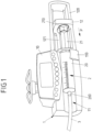
- Fig. 1 shows an infusion device 1 in the shape of a syringe pump having a housing 10 and a receptacle 11 arranged on the housing 10 to receive a syringe 2 therein.
- the syringe 2 comprises a cylindrical tube 20 which, when installing the syringe 2 on the infusion device 1, contains a medical liquid, for example a medication or a solution for the parenteral feeding, to be infused to a patient.
- the cylindrical tube 20 is connected, via a connector 200, to an infusion line 3 which may extend from the syringe 2 towards a patient for infusing the medical liquid to the patient.
- the cylindrical tube 20 of the syringe 2 is placed in the receptacle 11 and is mechanically connected to the housing 10 by means of a fixation device 110.
- the fixation device 110 for example constituted by a releasable clamp element, the cylindrical tube 20 is secured within the receptacle 11 such that the cylindrical tube 20 is held in position on the receptacle 11.
- the syringe 2 comprises a piston 21 which, for delivering medical fluid contained in the cylindrical tube 20, can be pushed into the cylindrical tube 20 in a pushing direction P.
- the infusion device 1 comprises a pusher device 12 movably arranged within a guide device 120 and connected to a drive mechanism (which subsequently shall be described with relation to Fig. 2 and 3 ) via a connecting rod 121.
- the syringe 2 is installed on the infusion device 1 and the pusher device 12 is (manually) moved towards a piston head 210 of the piston 21 until the pusher device 12 comes into abutment with the piston head 210.
- the pusher device 12 is then electrically moved in the pushing direction P to move the piston 21 into the cylindrical tube 20 for delivering the medical fluid contained in the cylindrical tube 20 via the infusion line 3 towards the patient.
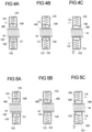
- the pusher device 12 is driven by a drive mechanism, which, according to one embodiment, is schematically illustrated in Fig. 2 .
- the drive mechanism comprises a drive element 13, which is connected to the pusher device 12 we a connecting rod 121 in a mechanically fixed manner such that by moving the drive element 13 the pusher device 12 is moved along the pushing direction P.
- the drive element 13 is movable within the housing 10 along the pushing direction P and, via a clutching device 130, is (releasably) connected to a driving rod 14 having a screw thread 140.
- the clutching device 130 comprises two clutch elements 130 which each are pivotably connected, about an associated pivot axis 134, to a frame member 131 of the drive element 13.
- the clutch elements 130 each are shaped as a half nut and comprise a screw thread 132 by which they may engage with the screw thread 140 of the driving rod 14.
- the clutch elements 130 are pivoted towards each other in a clutching direction C such that they receive the driving rod 14 in between them and engage with the screw thread 140 of the driving rod 14.
- the clutch elements 130 are pivoted opposite to the clutching direction C away from one another, such that they disengage from the screw thread 140 of the driving rod 14 and hence release the connection between the drive element 13 and the driving rod 14.
- the clutch device is in the clutched state in which the clutch elements 130 engage with the screw thread 140 of the driving rod 14.
- the driving rod 14, at one end, is connected to an electric drive motor 141 and at the other end is received in a bearing 142 such that, driven by the electric drive motor 141, the driving rod 14 can be rotated about an axis of rotation R1.
- the drive element 13 due to the engagement of the clutch elements 130 with the screw thread 140 of the driving rod 14
- the pusher device 12 pushes the piston 21 in the pushing direction P into the cylindrical tube 20 of the syringe 2.
- the drive element 13 is operatively connected to a brake device 16 having a threaded spindle 160 which is rotatable, within bearings 161, about a rotational axis R2.
- the drive element 13 comprises an engagement opening 133 having a screw thread therein which engages with a screw thread of the threaded spindle 160.
- a longitudinal movement of the drive element 13 along the pushing direction P hence causes, due to the engagement, the threaded spindle 160 to be rotated about the rotational axis R2, which generally may be possible at low force if the screw thread of the threaded spindle 160 has a comparatively large pitch.
- the threaded spindle 160 at one end, is associated with a brake 162 constituted for example by an electromagnetic brake. If the brake 162 is activated, it blocks a rotation of the threaded spindle 160 about its rotational axis R2. If the threaded spindle 160 is not able to rotate, the drive element 13 cannot move along the threaded spindle 160 such that the drive element 13 is held in position and hence is braked by the brake device 16. If the brake 162 in contrast is deactivated, the threaded spindle 160 is allowed to rotate, such that the drive element 13 is not braked and may be moved longitudinally along the threaded spindle 160.
- a brake 162 constituted for example by an electromagnetic brake. If the brake 162 is activated, it blocks a rotation of the threaded spindle 160 about its rotational axis R2. If the threaded spindle 160 is not able to rotate, the drive element 13 cannot move along the threaded spindle 160 such that the drive element 13 is held in position and hence
- control device 17 acts onto the electric drive device 141 to rotate the driving rod 14, and the control device 17 acts onto the brake 162 to switch the brake device 16 between its activated and its deactivated state.
- the clutch device implemented by the clutch elements 130 is actuatable by means of an actuation device 15, for example in the shape of a lever.
- the lever may be manually pressed to unclutch the clutch elements 130 from the driving rod 14, and may be released in order to revert the clutching device to its clutched state.
- the drive mechanism as schematically illustrated in Fig. 2 and 3 may, in one embodiment, be implemented by a mechanism as it is described in US 2012/015170 A1 , which shall be incorporated by reference herein.
- sensing devices 170, 171 are provided which serve to monitor an actuation state of the actuation device 15 and a contact between the pusher device 12 and the piston head 210 of the piston 21.
- a first sensing device 170 detects whether the clutching device is actuated to its unclutched state or its clutched state.
- the first sensing device 170 can for example be implemented by a mechanical switch, for example a micromechanical switch, for monitoring a position of a lever of the actuation device 15.
- a second sensing device 171 serves to detect whether the pusher device 12 is in contact with the piston head 210 of the piston 21 and may be implemented for example by a force sensor, such as piezoelectric sensor, or by a mechanical switch, for example a micromechanical switch.
- the sensing devices 170, 171 both issue sensor signals which are fed to the control device 17 and may be used for controlling the operation of the infusion device 1.
- the pusher device 12 is manually moved such that it comes into contact with the piston 21.
- the clutching device is activated by means of the activation device 15 to its unclutched state, such that the drive element 13 can freely be moved along the driving rod 14.
- the clutching device is manually brought into engagement with the driving rod 14 by releasing the lever of the actuation device 15.
- the clutching device is unclutched such that the pusher device 12 is manually movable, and, after the manual bolus has been performed, is manually reverted to its clutched state such that the regular infusion operation may resume.
- the clutch elements 130 placed movably within the frame member 131 of the drive element 13 and being pretensioned by means of spring elements 135 towards their clutched state, are actuated to come into engagement with the screw thread 140 of the driving rod 14, they may come into contact, with their threads 132, with flanks of the screw thread 140 of the driving rod 14 and may slide, as shown in Fig. 4B , in a direction C1 into engagement with the screw thread 140 of the driving rod 14. This may lead to a forward movement of the drive element 13 in a direction C2, and may lead to an unwanted bolus because the forward movement in the direction C2 may cause the pusher device 12 to push against the piston 21 and hence to deliver an amount of liquid to the patient.
- the clutch elements 130 when moved to come into engagement with the screw thread 140 of the driving rod 14, come into contact with opposite flanks of the screw thread 140, the clutch elements 130 may slide in a direction C3 ( Fig. 5B ) into engagement with the screw thread 140, causing a backward movement of the drive element 13 in a direction C4, as illustrated in Fig. 5C .
- This may cause the pusher device 12 to be moved opposite to the pushing direction P and hence away from the piston head 210 of the piston 21, such that a gap between the pusher device 12 and the piston head 210 occurs, possibly causing a delay during a subsequent startup of an infusion operation.
- the clutch elements 130 may even not come into engagement with the screw thread 140 of the driving rod 14 at all, if the clutch elements 130 come to rest at tooth crests of the screw thread 140, as illustrated in Fig. 6B .
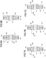
- control device 17 is constituted to perform a control sequence, which shall be described subsequently according to Fig. 7A-7C to 9A , 9B .
- Fig. 7A to 7C depict a scenario in which the clutch elements 130 are (initially) unclutched in order to allow a manual movement of the pusher device 12 together with the drive element 13 in order to bring the pusher device 12 into contact with the piston 21 during installation of the syringe 2 on the infusion device 1.
- the drive element 13 as depicted in Fig. 7A , is movable relative to the housing 10 along the pushing direction P.
- the brake device 16 is in its deactivated state and hence does not hinder a movement of the drive element 13.
- the control device 17 causes the brake device 16 to be activated such that the drive element 13 can no longer be moved relative to the threaded spindle 160 and hence is fixedly held in the housing 10. This is illustrated in Fig. 7B .
- control device 17 To cause the clutch elements 130 to fully engage with the screw thread 140 of the driving rod 14, the control device 17 now performs a control sequence by repeatedly actuating the electric drive motor 141 to rotate the driving rod 14.
- the driving rod 14 is rotated in a first rotational direction D1, corresponding to a backward movement E1 (which would cause a backward travel in the direction E1 of the drive element 13 in normal operation).
- the rotation of the driving rod 14 takes place for a predetermined time or for a predetermined angle of rotation, which may depend on the pitch of the screw thread 140 of the driving rod 14 and is chosen such that the clutch elements 130 may fully slide into engagement with the screw thread 140 of the driving rod 14. Because the drive element 13 still is mechanically held in position by the brake device 16, this takes place at no lateral movement of the drive element 13.
- the control device 17 then causes the electric drive device 141 to rotate the driving rod 14 in an opposite, second rotational direction D2 corresponding to a forward movement in the direction E2 (which would cause a forward travel in the direction E2 of the drive element 13 in normal operation).
- This forward movement in the direction E2 coincides with the pushing direction P and serves to overcome a play X (see for example Fig.4C ) which the clutch elements 130 may have relative to the frame member 131 of the drive element 13.
- the clutch elements 130 are in complete engagement with the screw thread 140 of the driving rod 14 and furthermore abut the frame member 131 of the drive element 13 in the pushing direction P.
- the brake device 16 is deactivated such that a regular infusion operation may start by rotating the driving rod 14 in the second rotational direction D2 and by hence moving the drive element 13 forward within the housing 10 in the pushing direction P.
- the control sequence may also be carried out after a manual bolus has been performed, as it is illustrated in Fig. 8A and 8B .
- the clutch elements 130 are unclutched from the driving rod 14 such that the pusher device 12 together with the drive element 13 may be moved in the pushing direction P to cause a bolus to be infused to the patient. This is illustrated in Fig. 8A .
- the actuation device 15 is activated for example by releasing a lever such that the clutch elements 130 are approached to the driving rod 14 to engage with the screw thread 140, as it is illustrated in Fig. 8B . If this is detected by the first sensing device 170, the control device 17 causes the brake device 16 to be activated such that the drive element 13 is fixedly held relative to the housing 10 and can no longer be moved.
- the installation of a syringe 2 on an infusion device 1 can be carried out in a semi-automatic fashion in that the pusher device 12 is manually brought into contact with the piston head 210 of the piston 21 of the syringe 2, and complete engagement between the clutch elements 130 and the driving rod 14 is ensured by an automatic control sequence controlled by the control device 17.
- This allows for a fast installation procedure as well as a reliable clutching engagement, without the risk for a gap in between the pusher device 12 and the piston head 210 after installation or an unwanted bolus.
- the device and method furthermore allow to perform a manual bolus, and to reliably establish a clutching engagement after the bolus has been given, without the risk for a gap in between the pusher device 12 and the piston head 210 after re-establishing the clutching or an unwanted bolus.
- the brake device may have an entirely different shape and may be constituted by a brake other than an electromagnetic brake.
- Infusion devices of the kind described herein may serve different purposes and may be constituted to receive syringes of different shape and different size.
- An infusion device of this kind may in particular not be limited to a particular type of syringe as it may be described herein.
Landscapes
- Health & Medical Sciences (AREA)
- Vascular Medicine (AREA)
- Engineering & Computer Science (AREA)
- Anesthesiology (AREA)
- Biomedical Technology (AREA)
- Heart & Thoracic Surgery (AREA)
- Hematology (AREA)
- Life Sciences & Earth Sciences (AREA)
- Animal Behavior & Ethology (AREA)
- General Health & Medical Sciences (AREA)
- Public Health (AREA)
- Veterinary Medicine (AREA)
- Infusion, Injection, And Reservoir Apparatuses (AREA)
Claims (10)
- Infusionsvorrichtung (1) zum Verabreichen eines medizinischen Fluids an einen Patienten, die Folgendes umfasst:- ein Gehäuse (10),- eine am Gehäuse (10) angeordneten Aufnahme (11) zur Aufnahme einer Spritze (2),- eine in einer Schubrichtung (P) bewegliche Schiebervorrichtung (12) zum Einwirken auf einen Kolben (21) einer an der Aufnahme (11) aufgenommenen Spritze (2),- ein mit der Schiebervorrichtung (12) verbundenes Antriebselement (13), wobei das Antriebselement (13) relativ zum Gehäuse (10) längsbeweglich ist, um die Schiebervorrichtung (12) entlang der Schubrichtung (P) zu bewegen,- eine Antriebsstange (14), die ein Schraubgewinde (140) aufweist und um eine Drehachse (R1) drehbar ist,- eine elektrische Antriebsvorrichtung (141) zum Drehen der Antriebsstange (14),- eine Kupplungsvorrichtung (130), die mit dem Antriebselement (13) verbunden ist und durch eine Betätigungsvorrichtung (15) betätigt werden kann, um in einem eingekuppelten Zustand mit dem Schraubgewinde (140) der Antriebsstange (14) in Eingriff zu kommen, um eine Drehbewegung der Antriebsstange (14) in eine Längsbewegung des Antriebselements (13) entlang der Antriebsstange (14) umzusetzen, und um sich in einem ungekuppelten Zustand von der Antriebsstange (14) zu lösen,- eine Bremsvorrichtung (16), die dazu ausgebildet ist, in einem aktivierten Zustand auf das Antriebselement (13) zum Abbremsen des Antriebselements (13) relativ zum Gehäuse (10) zu wirken und um in einem deaktivierten Zustand eine Längsbewegung des Antriebselements (13) relativ zum Gehäuse (10) zu ermöglichen,- eine Steuervorrichtung (17) zur Steuerung der elektrischen Antriebsvorrichtung (141) und der Bremsvorrichtung (16), und- eine Sensorvorrichtung (170) zum Erkennen eines Betätigungszustandes der Kupplungsvorrichtung (130),dadurch gekennzeichnet,
dass die Steuervorrichtung (17) ausgebildet ist, wenn die Sensorvorrichtung (170) erkennt, dass die Kupplungsvorrichtung (130) betätigt wird, um vom ungekuppelten Zustand in den eingekuppelten Zustand zu wechseln, eine Steuersequenz durchzuführen, während der die Steuervorrichtung (17) die elektrische Antriebsvorrichtung (141) steuert, um die Antriebsstange (14) für eine vorbestimmte Dauer oder für einen vorbestimmten Drehwinkel zu drehen, während sich die Bremsvorrichtung (16) im aktivierten Zustand befindet. - Infusionsvorrichtung (1) nach Anspruch 1, dadurch gekennzeichnet, dass die Steuervorrichtung (17) dazu ausgebildet ist, die Bremsvorrichtung (16) zu betätigen, um den aktivierten Zustand einzunehmen, wenn die Sensorvorrichtung (170) erkennt, dass die Kupplungsvorrichtung (130) durch die Betätigungsvorrichtung (15) betätigt wird, um vom ungekuppelten Zustand in den eingekuppelten Zustand zu wechseln.
- Infusionsvorrichtung (1) nach Anspruch 1 oder 2, gekennzeichnet durch eine zweite Sensorvorrichtung (171), die dazu ausgebildet ist, einen Anschlag der Schiebervorrichtung (12) an den Kolben (21) der Spritze (2) zu erkennen.
- Infusionsvorrichtung (1) nach Anspruch 3, dadurch gekennzeichnet, dass die Steuervorrichtung (17) ausgebildet ist, während sich die Kupplungsvorrichtung (130) im ungekuppelten Zustand befindet, die Bremsvorrichtung (16) zu betätigen, um den aktivierten Zustand einzunehmen, wenn die zweite Sensorvorrichtung (171) erkennt, dass die Schiebervorrichtung (12) in Anlage mit dem Kolben (21) gekommen ist.
- Infusionsvorrichtung (1) nach einem der vorhergehenden Ansprüche, dadurch gekennzeichnet, dass die Steuervorrichtung (17) ausgebildet ist, bei der Durchführung der Steuersequenz die elektrische Antriebsvorrichtung (141) zu steuern, um die Antriebsstange (14) für eine erste vorgegebene Zeitdauer oder einen ersten vorgegebenen Drehwinkel in eine erste Drehrichtung (D1) zu drehen und die Antriebsstange (14) anschließend für eine zweite vorgegebene Zeitdauer oder einen zweiten vorgegebenen Drehwinkel in eine der ersten Drehrichtung (D1) entgegengesetzte zweite Drehrichtung (D2) zu drehen.
- Infusionsvorrichtung (1) nach Anspruch 5, dadurch gekennzeichnet, dass die erste Drehrichtung (D1) einer Rückwärtsdrehung zum Bewegen des Antriebselements (13) in eine der Schubrichtung (P) entgegengesetzte Richtung entspricht und die zweite Drehrichtung (D2) einer Vorwärtsdrehung zum Bewegen des Antriebselements (13) in die Schubrichtung (P) entspricht.
- Infusionsvorrichtung (1) nach einem der vorhergehenden Ansprüche, dadurch gekennzeichnet, dass die Steuervorrichtung (17) dazu ausgebildet ist, die Bremsvorrichtung (16) zu steuern, um den aktivierten Zustand einzunehmen, nachdem die Antriebsstange (14) gedreht wurde.
- Infusionsvorrichtung (1) nach einem der vorhergehenden Ansprüche, dadurch gekennzeichnet, dass die Kupplungsvorrichtung ein Paar Kupplungselemente (130) umfasst, die beweglich am Antriebselement (13) angeordnet sind und jeweils ein Schraubgewinde (132) zum Eingriff mit dem Schraubgewinde (140) der Antriebsstange (14) aufweisen.
- Infusionsvorrichtung (1) nach Anspruch 8, dadurch gekennzeichnet, dass die Kupplungselemente (130) schwenkbar an einem Rahmenelement (131) des Antriebselements (13) angeordnet sind.
- Verfahren zum Inbetriebsetzen einer Infusionsvorrichtung (1), wobei:- eine Spritze (2) in einer an einem Gehäuse (10) der Infusionsvorrichtung (1) angeordneten Aufnahme (11) aufgenommen ist,- sich eine Schiebervorrichtung (12) in einem deaktivierten Zustand einer Bremsvorrichtung in einer Schubrichtung (P) bewegen kann, um auf einen Kolben (21) der an der Aufnahme (11) aufgenommenen Spritze (2) einzuwirken,- sich ein mit der Schiebervorrichtung (12) verbundenes Antriebselement (13) in einem deaktivierten Zustand einer Bremsvorrichtung relativ zum Gehäuse (10) in Längsrichtung bewegen kann, um die Schiebervorrichtung (12) entlang der Schubrichtung (P) zu bewegen,- eine Antriebsstange (14), die ein Schraubgewinde (140) aufweist, von einer elektrischen Antriebsvorrichtung (141) um eine Drehachse (R1) gedreht wird,- eine mit dem Antriebselement (13) verbundene Kupplungsvorrichtung (130) durch eine Betätigungsvorrichtung (15) betätigt werden kann, um in einem eingekuppelten Zustand mit dem Schraubgewinde (140) der Antriebsstange (14) in Eingriff zu kommen, um eine Drehbewegung der Antriebsstange (14) in eine Längsbewegung des Antriebselements (13) entlang der Antriebsstange (14) umzusetzen, und um sich in einem ungekuppelten Zustand von der Antriebsstange (14) zu lösen, und- eine Bremsvorrichtung (16) dazu ausgebildet ist, in einem aktivierten Zustand auf das Antriebselement (13) zum Abbremsen des Antriebselements (13) relativ zum Gehäuse (10) zu wirken und um in einem deaktivierten Zustand eine Längsbewegung des Antriebselements (13) relativ zum Gehäuse (10) zu ermöglichen, und- eine Steuervorrichtung (17) die elektrische Antriebsvorrichtung (141) und die Bremsvorrichtung (16) steuert, und- eine Sensorvorrichtung (170) einen Betätigungszustand der Kupplungsvorrichtung (130) erkennt,dadurch gekennzeichnet,
dass die Steuervorrichtung (17), wenn die Sensorvorrichtung (170) erkennt, dass die Kupplungsvorrichtung (130) betätigt wird, um vom ungekuppelten Zustand in den eingekuppelten Zustand zu wechseln, eine Steuersequenz durchführt, während der die Steuervorrichtung (17) die elektrische Antriebsvorrichtung (141) steuert, um die Antriebsstange (14) für eine vorbestimmte Dauer oder für einen vorbestimmten Drehwinkel zu drehen, während sich die Bremsvorrichtung (16) im aktivierten Zustand befindet.
Applications Claiming Priority (2)
| Application Number | Priority Date | Filing Date | Title |
|---|---|---|---|
| EP15306557 | 2015-10-05 | ||
| PCT/EP2016/073385 WO2017060166A1 (en) | 2015-10-05 | 2016-09-30 | Infusion device for administering a medical fluid to a patient and method for operating an infusion device |
Publications (3)
| Publication Number | Publication Date |
|---|---|
| EP3359226A1 EP3359226A1 (de) | 2018-08-15 |
| EP3359226C0 EP3359226C0 (de) | 2024-12-04 |
| EP3359226B1 true EP3359226B1 (de) | 2024-12-04 |
Family
ID=54266507
Family Applications (1)
| Application Number | Title | Priority Date | Filing Date |
|---|---|---|---|
| EP16774680.9A Active EP3359226B1 (de) | 2015-10-05 | 2016-09-30 | Infusionsvorrichtung zur verabreichung einer medizinischen flüssigkeit an einen patienten und verfahren zum betrieb einer infusionsvorrichtung |
Country Status (4)
| Country | Link |
|---|---|
| US (1) | US11147917B2 (de) |
| EP (1) | EP3359226B1 (de) |
| CN (1) | CN108136124B (de) |
| WO (1) | WO2017060166A1 (de) |
Families Citing this family (10)
| Publication number | Priority date | Publication date | Assignee | Title |
|---|---|---|---|---|
| WO2014106008A1 (en) | 2012-12-28 | 2014-07-03 | Gambro Renal Products, Inc. | Syringe pump engagement detection apparatus and methods |
| CN109529158A (zh) * | 2018-11-06 | 2019-03-29 | 李长寿 | 一种人体抗体疫苗注射器 |
| US12048830B2 (en) | 2019-03-07 | 2024-07-30 | Kpr U.S., Llc | Delivery of fluid from a syringe |
| CN113543823B (zh) * | 2019-05-17 | 2023-12-15 | 上海移宇科技有限公司 | 药物输注装置 |
| EP3750573A1 (de) * | 2019-06-14 | 2020-12-16 | Fresenius Vial SAS | Infusionsvorrichtung mit einer bremsvorrichtung |
| EP3756724A1 (de) | 2019-06-26 | 2020-12-30 | Fresenius Vial SAS | Klemmvorrichtung zur befestigung einer medizinischen vorrichtung an einem träger |
| JP7449293B2 (ja) * | 2019-08-07 | 2024-03-13 | テルモ株式会社 | 駆動装置及び医療用ポンプ |
| CN111173729A (zh) | 2019-12-27 | 2020-05-19 | 南微医学科技股份有限公司 | 一种压力泵泵头及压力泵 |
| CN112156279B (zh) * | 2020-10-21 | 2024-12-10 | 苏州天合云朵医疗科技有限公司 | 智能监测注射剂量的方法、装置、注射器、系统和介质 |
| WO2025061651A1 (en) * | 2023-09-18 | 2025-03-27 | Fresenius Vial Sas | Infusion device with a differential transmission |
Family Cites Families (14)
| Publication number | Priority date | Publication date | Assignee | Title |
|---|---|---|---|---|
| GB1595972A (en) * | 1977-03-09 | 1981-08-19 | Nat Res Dev | Syringe driving apparatus |
| DE3838465A1 (de) | 1988-11-12 | 1990-05-17 | Fresenius Ag | Spritzenpumpe |
| US5106375A (en) * | 1991-05-23 | 1992-04-21 | Ivac Corporation | Dynamic lead screw engagement and indicator |
| DE20200885U1 (de) | 2002-01-22 | 2003-05-28 | B. Braun Melsungen Ag, 34212 Melsungen | Spritzenpumpe mit Kolbenbremse |
| US7144384B2 (en) | 2002-09-30 | 2006-12-05 | Insulet Corporation | Dispenser components and methods for patient infusion device |
| US7543516B2 (en) | 2005-07-22 | 2009-06-09 | Cardinal Health 303, Inc. | Dynamic lead screw thread engagement system and method |
| CN100545487C (zh) * | 2008-04-22 | 2009-09-30 | 南京数控机床有限公司 | 一种机械传动时的间隙消除机构 |
| EP2281851B1 (de) | 2009-07-01 | 2011-09-07 | Borealis AG | Polypropylenzusammensetzung mit hohem Durchfluss |
| FR2950811B1 (fr) | 2009-10-02 | 2012-10-26 | Fresenius Vial | Procede de controle antibolus et dispositif correspondant |
| US9789247B2 (en) * | 2011-12-21 | 2017-10-17 | Deka Products Limited Partnership | Syringe pump, and related method and system |
| JP2013540027A (ja) | 2010-10-25 | 2013-10-31 | サノフィ−アベンティス・ドイチュラント・ゲゼルシャフト・ミット・ベシュレンクテル・ハフツング | 薬剤送達デバイス |
| JP5510395B2 (ja) * | 2011-06-16 | 2014-06-04 | パナソニック株式会社 | 部品実装装置及び部品実装方法 |
| EP2606922B1 (de) | 2011-12-23 | 2017-02-15 | B. Braun Melsungen AG | Infusionspumpe mit Antriebsvorrichtung und Blockiereinrichtung für den Infusionsspritzenkolbenantriebskopf |
| DE102013214221B3 (de) * | 2013-04-09 | 2014-06-18 | Johnson Controls Gmbh | Vorrichtung und Verfahren zur Blockierung einer Schnellverstellung einer Gewindespindel |
-
2016
- 2016-09-30 US US15/757,908 patent/US11147917B2/en active Active
- 2016-09-30 WO PCT/EP2016/073385 patent/WO2017060166A1/en not_active Ceased
- 2016-09-30 CN CN201680057734.0A patent/CN108136124B/zh active Active
- 2016-09-30 EP EP16774680.9A patent/EP3359226B1/de active Active
Also Published As
| Publication number | Publication date |
|---|---|
| US11147917B2 (en) | 2021-10-19 |
| CN108136124A (zh) | 2018-06-08 |
| EP3359226C0 (de) | 2024-12-04 |
| EP3359226A1 (de) | 2018-08-15 |
| WO2017060166A1 (en) | 2017-04-13 |
| CN108136124B (zh) | 2022-09-06 |
| US20200030526A1 (en) | 2020-01-30 |
Similar Documents
| Publication | Publication Date | Title |
|---|---|---|
| EP3359226B1 (de) | Infusionsvorrichtung zur verabreichung einer medizinischen flüssigkeit an einen patienten und verfahren zum betrieb einer infusionsvorrichtung | |
| US11364338B2 (en) | Infusion device having a clutching device | |
| JP5784023B2 (ja) | ボーラスを防止する制御方法およびその装置 | |
| EP3222307B1 (de) | Infusionsvorrichtung zur verabreichung eines medizinischen fluids an einen patienten | |
| RU2619999C2 (ru) | Инфузионный насос с приводным устройством и блокировочным механизмом для приводной головки поршня инфузионного шприца | |
| WO2013079226A1 (de) | Antriebsvorrichtung zum linearen bewegen eines infusionsspritzenkolbens, infusionspumpe und verfahren zum auswechseln einer infusionsspritze | |
| EP3920999B1 (de) | Infusionsvorrichtung zur verabreichung einer medizinischen flüssigkeit an einen patienten | |
| US20250082845A1 (en) | Infusion Device Having a Drive Mechanism for Driving a Pusher Device | |
| EP3503942B1 (de) | Tragbare vorrichtung zur abgabe eines flüssigen arzneimittels | |
| US20220249770A1 (en) | Infusion device having a brake device | |
| HK40060675A (en) | Infusion device for administering a medical fluid to a patient | |
| HK40060675B (en) | Infusion device for administering a medical fluid to a patient |
Legal Events
| Date | Code | Title | Description |
|---|---|---|---|
| STAA | Information on the status of an ep patent application or granted ep patent |
Free format text: STATUS: UNKNOWN |
|
| STAA | Information on the status of an ep patent application or granted ep patent |
Free format text: STATUS: THE INTERNATIONAL PUBLICATION HAS BEEN MADE |
|
| PUAI | Public reference made under article 153(3) epc to a published international application that has entered the european phase |
Free format text: ORIGINAL CODE: 0009012 |
|
| STAA | Information on the status of an ep patent application or granted ep patent |
Free format text: STATUS: REQUEST FOR EXAMINATION WAS MADE |
|
| 17P | Request for examination filed |
Effective date: 20180507 |
|
| AK | Designated contracting states |
Kind code of ref document: A1 Designated state(s): AL AT BE BG CH CY CZ DE DK EE ES FI FR GB GR HR HU IE IS IT LI LT LU LV MC MK MT NL NO PL PT RO RS SE SI SK SM TR |
|
| AX | Request for extension of the european patent |
Extension state: BA ME |
|
| DAV | Request for validation of the european patent (deleted) | ||
| DAX | Request for extension of the european patent (deleted) | ||
| STAA | Information on the status of an ep patent application or granted ep patent |
Free format text: STATUS: EXAMINATION IS IN PROGRESS |
|
| 17Q | First examination report despatched |
Effective date: 20220621 |
|
| GRAP | Despatch of communication of intention to grant a patent |
Free format text: ORIGINAL CODE: EPIDOSNIGR1 |
|
| STAA | Information on the status of an ep patent application or granted ep patent |
Free format text: STATUS: GRANT OF PATENT IS INTENDED |
|
| INTG | Intention to grant announced |
Effective date: 20240711 |
|
| GRAS | Grant fee paid |
Free format text: ORIGINAL CODE: EPIDOSNIGR3 |
|
| GRAA | (expected) grant |
Free format text: ORIGINAL CODE: 0009210 |
|
| STAA | Information on the status of an ep patent application or granted ep patent |
Free format text: STATUS: THE PATENT HAS BEEN GRANTED |
|
| AK | Designated contracting states |
Kind code of ref document: B1 Designated state(s): AL AT BE BG CH CY CZ DE DK EE ES FI FR GB GR HR HU IE IS IT LI LT LU LV MC MK MT NL NO PL PT RO RS SE SI SK SM TR |
|
| REG | Reference to a national code |
Ref country code: GB Ref legal event code: FG4D |
|
| REG | Reference to a national code |
Ref country code: CH Ref legal event code: EP |
|
| REG | Reference to a national code |
Ref country code: DE Ref legal event code: R096 Ref document number: 602016090509 Country of ref document: DE |
|
| REG | Reference to a national code |
Ref country code: IE Ref legal event code: FG4D |
|
| U01 | Request for unitary effect filed |
Effective date: 20241219 |
|
| U07 | Unitary effect registered |
Designated state(s): AT BE BG DE DK EE FI FR IT LT LU LV MT NL PT RO SE SI Effective date: 20250110 |
|
| PG25 | Lapsed in a contracting state [announced via postgrant information from national office to epo] |
Ref country code: HR Free format text: LAPSE BECAUSE OF FAILURE TO SUBMIT A TRANSLATION OF THE DESCRIPTION OR TO PAY THE FEE WITHIN THE PRESCRIBED TIME-LIMIT Effective date: 20241204 |
|
| PG25 | Lapsed in a contracting state [announced via postgrant information from national office to epo] |
Ref country code: ES Free format text: LAPSE BECAUSE OF FAILURE TO SUBMIT A TRANSLATION OF THE DESCRIPTION OR TO PAY THE FEE WITHIN THE PRESCRIBED TIME-LIMIT Effective date: 20241204 |
|
| PG25 | Lapsed in a contracting state [announced via postgrant information from national office to epo] |
Ref country code: NO Free format text: LAPSE BECAUSE OF FAILURE TO SUBMIT A TRANSLATION OF THE DESCRIPTION OR TO PAY THE FEE WITHIN THE PRESCRIBED TIME-LIMIT Effective date: 20250304 |
|
| PG25 | Lapsed in a contracting state [announced via postgrant information from national office to epo] |
Ref country code: GR Free format text: LAPSE BECAUSE OF FAILURE TO SUBMIT A TRANSLATION OF THE DESCRIPTION OR TO PAY THE FEE WITHIN THE PRESCRIBED TIME-LIMIT Effective date: 20250305 |
|
| PG25 | Lapsed in a contracting state [announced via postgrant information from national office to epo] |
Ref country code: RS Free format text: LAPSE BECAUSE OF FAILURE TO SUBMIT A TRANSLATION OF THE DESCRIPTION OR TO PAY THE FEE WITHIN THE PRESCRIBED TIME-LIMIT Effective date: 20250304 |
|
| PG25 | Lapsed in a contracting state [announced via postgrant information from national office to epo] |
Ref country code: SM Free format text: LAPSE BECAUSE OF FAILURE TO SUBMIT A TRANSLATION OF THE DESCRIPTION OR TO PAY THE FEE WITHIN THE PRESCRIBED TIME-LIMIT Effective date: 20241204 |
|
| PG25 | Lapsed in a contracting state [announced via postgrant information from national office to epo] |
Ref country code: PL Free format text: LAPSE BECAUSE OF FAILURE TO SUBMIT A TRANSLATION OF THE DESCRIPTION OR TO PAY THE FEE WITHIN THE PRESCRIBED TIME-LIMIT Effective date: 20241204 |
|
| PG25 | Lapsed in a contracting state [announced via postgrant information from national office to epo] |
Ref country code: IS Free format text: LAPSE BECAUSE OF FAILURE TO SUBMIT A TRANSLATION OF THE DESCRIPTION OR TO PAY THE FEE WITHIN THE PRESCRIBED TIME-LIMIT Effective date: 20250404 |
|
| PG25 | Lapsed in a contracting state [announced via postgrant information from national office to epo] |
Ref country code: SK Free format text: LAPSE BECAUSE OF FAILURE TO SUBMIT A TRANSLATION OF THE DESCRIPTION OR TO PAY THE FEE WITHIN THE PRESCRIBED TIME-LIMIT Effective date: 20241204 |
|
| PG25 | Lapsed in a contracting state [announced via postgrant information from national office to epo] |
Ref country code: CZ Free format text: LAPSE BECAUSE OF FAILURE TO SUBMIT A TRANSLATION OF THE DESCRIPTION OR TO PAY THE FEE WITHIN THE PRESCRIBED TIME-LIMIT Effective date: 20241204 |
|
| PLBE | No opposition filed within time limit |
Free format text: ORIGINAL CODE: 0009261 |
|
| STAA | Information on the status of an ep patent application or granted ep patent |
Free format text: STATUS: NO OPPOSITION FILED WITHIN TIME LIMIT |
|
| PGFP | Annual fee paid to national office [announced via postgrant information from national office to epo] |
Ref country code: GB Payment date: 20250929 Year of fee payment: 10 |
|
| U20 | Renewal fee for the european patent with unitary effect paid |
Year of fee payment: 10 Effective date: 20250930 |
|
| 26N | No opposition filed |
Effective date: 20250905 |