EP3358483B1 - Transfer of a data set - Google Patents
Transfer of a data set Download PDFInfo
- Publication number
- EP3358483B1 EP3358483B1 EP17154830.8A EP17154830A EP3358483B1 EP 3358483 B1 EP3358483 B1 EP 3358483B1 EP 17154830 A EP17154830 A EP 17154830A EP 3358483 B1 EP3358483 B1 EP 3358483B1
- Authority
- EP
- European Patent Office
- Prior art keywords
- item
- information
- monitored device
- unit
- data record
- Prior art date
- Legal status (The legal status is an assumption and is not a legal conclusion. Google has not performed a legal analysis and makes no representation as to the accuracy of the status listed.)
- Active
Links
- 230000000007 visual effect Effects 0.000 claims description 60
- 238000012544 monitoring process Methods 0.000 claims description 53
- 230000005540 biological transmission Effects 0.000 claims description 47
- 238000000034 method Methods 0.000 claims description 35
- 230000008859 change Effects 0.000 claims description 32
- 230000006870 function Effects 0.000 claims description 31
- 230000003287 optical effect Effects 0.000 claims description 22
- 238000004590 computer program Methods 0.000 claims description 16
- 238000009434 installation Methods 0.000 claims description 3
- 238000001514 detection method Methods 0.000 claims 7
- 235000019646 color tone Nutrition 0.000 claims 1
- 238000012545 processing Methods 0.000 description 9
- 238000002604 ultrasonography Methods 0.000 description 6
- 238000004891 communication Methods 0.000 description 3
- 239000011159 matrix material Substances 0.000 description 3
- 230000001105 regulatory effect Effects 0.000 description 3
- 239000012080 ambient air Substances 0.000 description 2
- 230000008901 benefit Effects 0.000 description 2
- 238000012937 correction Methods 0.000 description 2
- 230000005670 electromagnetic radiation Effects 0.000 description 2
- 238000003384 imaging method Methods 0.000 description 2
- 230000004044 response Effects 0.000 description 2
- 230000007480 spreading Effects 0.000 description 2
- 238000013519 translation Methods 0.000 description 2
- 229910002056 binary alloy Inorganic materials 0.000 description 1
- 230000001413 cellular effect Effects 0.000 description 1
- 238000013523 data management Methods 0.000 description 1
- 230000001419 dependent effect Effects 0.000 description 1
- 238000005516 engineering process Methods 0.000 description 1
- 230000007246 mechanism Effects 0.000 description 1
- 230000004048 modification Effects 0.000 description 1
- 238000012986 modification Methods 0.000 description 1
- 230000009897 systematic effect Effects 0.000 description 1
- 238000001429 visible spectrum Methods 0.000 description 1
Images


Classifications
-
- G—PHYSICS
- G06—COMPUTING; CALCULATING OR COUNTING
- G06K—GRAPHICAL DATA READING; PRESENTATION OF DATA; RECORD CARRIERS; HANDLING RECORD CARRIERS
- G06K7/00—Methods or arrangements for sensing record carriers, e.g. for reading patterns
- G06K7/10—Methods or arrangements for sensing record carriers, e.g. for reading patterns by electromagnetic radiation, e.g. optical sensing; by corpuscular radiation
- G06K7/14—Methods or arrangements for sensing record carriers, e.g. for reading patterns by electromagnetic radiation, e.g. optical sensing; by corpuscular radiation using light without selection of wavelength, e.g. sensing reflected white light
- G06K7/1404—Methods for optical code recognition
- G06K7/1408—Methods for optical code recognition the method being specifically adapted for the type of code
- G06K7/1417—2D bar codes
-
- G—PHYSICS
- G16—INFORMATION AND COMMUNICATION TECHNOLOGY [ICT] SPECIALLY ADAPTED FOR SPECIFIC APPLICATION FIELDS
- G16H—HEALTHCARE INFORMATICS, i.e. INFORMATION AND COMMUNICATION TECHNOLOGY [ICT] SPECIALLY ADAPTED FOR THE HANDLING OR PROCESSING OF MEDICAL OR HEALTHCARE DATA
- G16H40/00—ICT specially adapted for the management or administration of healthcare resources or facilities; ICT specially adapted for the management or operation of medical equipment or devices
- G16H40/60—ICT specially adapted for the management or administration of healthcare resources or facilities; ICT specially adapted for the management or operation of medical equipment or devices for the operation of medical equipment or devices
- G16H40/67—ICT specially adapted for the management or administration of healthcare resources or facilities; ICT specially adapted for the management or operation of medical equipment or devices for the operation of medical equipment or devices for remote operation
-
- G—PHYSICS
- G06—COMPUTING; CALCULATING OR COUNTING
- G06K—GRAPHICAL DATA READING; PRESENTATION OF DATA; RECORD CARRIERS; HANDLING RECORD CARRIERS
- G06K7/00—Methods or arrangements for sensing record carriers, e.g. for reading patterns
- G06K7/10—Methods or arrangements for sensing record carriers, e.g. for reading patterns by electromagnetic radiation, e.g. optical sensing; by corpuscular radiation
- G06K7/10544—Methods or arrangements for sensing record carriers, e.g. for reading patterns by electromagnetic radiation, e.g. optical sensing; by corpuscular radiation by scanning of the records by radiation in the optical part of the electromagnetic spectrum
- G06K7/10712—Fixed beam scanning
- G06K7/10722—Photodetector array or CCD scanning
Definitions
- Such devices to be monitored are medical-technical systems, for example ultrasound devices or mobile X-ray devices, for which particularly strict regulatory requirements regularly apply.
- the object is achieved by a method according to claim 1, a data transmission system according to claim 13, a computer program product according to claim 15 and by a computer-readable storage medium according to claim 16.
- the invention is based on the fact that a configuration change on a monitored device is determined by means of a first processing unit of a monitored device. Furthermore, a first data set is determined by means of the first processing unit of the monitored device, the first data set comprising at least one piece of public device information and one piece of configuration information, and wherein the public device information can be uniquely assigned to the monitored device. Furthermore, visual information is determined based on the first data record by means of the first computing unit of the monitored device. Furthermore, the visual information is optically transmitted from an output unit of the monitored device to an input unit of a mobile monitoring unit.
- a second data record is determined from the visual information by means of a second processing unit of the mobile monitoring unit, with at least the public device information and the configuration information being able to be determined from the second data record. Furthermore, the second data record is transmitted from an interface of the mobile monitoring unit to a central data acquisition unit.
- the monitored device can in particular be a medical device, in particular an imaging device, in particular a mobile ultrasound device or a mobile C-arm X-ray device.
- the inventors have recognized that by transmitting the public device information and the configuration information to a mobile monitoring unit, a connection from the mobile monitoring unit to the central data acquisition unit, for example via the Internet, can be used. Therefore, the monitored device does not have to be connected directly to the central data acquisition unit, this leads to cost savings and better security of the monitored device. Furthermore, by using an optical transmission, it is not necessary to establish a permanent connection, for example a wired connection or a radio connection, between the monitored device and the mobile monitoring unit. The mobile monitoring unit can therefore be used, on the one hand, in particular for monitoring several monitored devices; this represents a cost saving. By using the optical transmission, the monitored device cannot be manipulated by a third party, since no information and in particular no malicious code is transmitted to the monitored device can be transmitted. Due to the optical transmission, it is also not necessary to manually record or pass on the public device information and the configuration information, so that the data record can be transmitted particularly quickly and efficiently to the central data recording unit, and careless mistakes by the user when recording the data are avoided.
- the configuration information includes at least one item of information about the success of the configuration change on the monitored device.
- a configuration change is particularly successful if the configuration change has been carried out successfully.
- the inventors have recognized that with such configuration information a correct database can be achieved in the central data acquisition unit in a particularly simple manner.
- the visual information is contained in an image, with the image being displayed on the output unit of the monitored system during the first optical transmission and the image being captured by the input unit of the mobile monitoring unit.
- Visual information is contained in an image in particular if it can be restored or reconstructed from the image alone.
- visual information is also contained in an image if the visual information is contained in the image in an encrypted or encoded form.
- the inventors have recognized that outputting an image on the output unit of the monitored device as well as capturing the image with the input unit of the mobile monitoring unit is particularly cost-effective and efficient, since the suitable output unit and the suitable input unit are usually already available and for displaying or Acquisition of an image are formed, and therefore the method can be carried out without costly modification of the monitored device or the mobile monitoring unit.
- the image comprises image areas, wherein an image area has either a first color or a second color, and wherein the first color and the second color differ at least in their brightness and / or in their hue.
- the first color and the second color can also differ in particular in terms of their brightness.
- the visual information is contained in the geometric arrangement of the image areas of the image.
- the inventors have recognized that this geometric arrangement is particularly good, fast and with special few errors can be recognized by the input unit of the mobile monitoring unit.
- the image comprises a one-dimensional bar code or a two-dimensional bar code.
- a one-dimensional bar code can in particular be a bar code
- a two-dimensional bar code can in particular be a stacked bar code, a matrix code or a point code.
- a two-dimensional barcode can in particular be a "Quick Response Code" ("QR code” for short, a German term is a quick response code).
- QR code Quality of Response Code
- a one-dimensional barcode or a two-dimensional barcode can in particular include redundant areas.
- the inventors have recognized that information can be transmitted particularly efficiently using a one-dimensional barcode or a two-dimensional barcode.
- one-dimensional barcodes and two-dimensional barcodes include redundant areas, so that errors during transmission are prevented. At the same time, the redundant areas also accelerate the optical transmission, since inaccuracies in positioning and image acquisition by the mobile monitoring unit can be compensated for by the error redundancy.
- the public device information comprises a first identification number of the monitored device.
- a first identification number can in particular be a serial number of the monitored device.
- An identification number can in particular also include characters that are not numeric, for example letters or special characters. The inventors have recognized that through the use of a first identification number, the data transmitted to the central data acquisition unit can be assigned to the monitored device particularly easily and thus quickly.
- the configuration change comprises installing and / or removing a Hardware and / or software component, wherein the configuration information includes a second identification number of the hardware and / or software component.
- the visual information is designed in such a way that a change in the configuration information and the public device information can be determined by means of the mobile monitoring unit and / or by means of the central data acquisition unit.
- the inventors have recognized that such transmission errors or deliberate manipulation of the data are excluded.
- the configuration information can in particular be stored in the central data acquisition unit without errors.
- the visual information comprises at least the result of applying a one-way scatter value function to the first data set.
- a technical term for one-way scatter function is "hash function". The inventors have recognized that by using a one-way scatter function, the change in the configuration information and the public device information can be determined particularly quickly; furthermore, the result of using a conventional one-way scatter function is short and can therefore be transmitted quickly and inexpensively.
- the first data record further comprises secret device information, the secret device information being uniquely assignable to the monitored device, and the secret device information not being determinable from the visual information.
- the secret device information is stored both in the central data acquisition unit and in the monitored device.
- the inventors have recognized that manipulation can be excluded in a particularly simple and inexpensive manner by means of such storage.
- the configuration change includes installing and / or removing a hardware and / or software component; the secret device information is also stored both in the central data acquisition unit and in the hardware and / or software component.
- the inventors have recognized that such storage can be particularly effective in preventing manipulation, since different secret device information can be selected for different configuration changes.
- the second identification number of the monitored device can be uniquely assigned, with the second identification number being stored both in the central data acquisition unit and in the new hardware and / or software component, and with the second identification number not being determinable from the visual information is.
- the inventors have recognized that security against manipulation can be guaranteed by means of such a second identification number without storing additional information in the monitored device.
- the second data record is a query part of a uniform resource pointer, the second transmission comprising calling up the uniform resource pointer.
- An English technical term for a uniform resource pointer is "Uniform Resource Locator "," URL "for short.
- An English technical term for the query part of a uniform resource pointer is" Query ".
- a uniform resource pointer can in particular be an electronic reference.
- An English technical term for an electronic reference is" Hyperlink ".
- the second transmission can then be through the call of the hyperlink can be carried out, the query part being transmitted to the destination of the call.
- This communication infrastructure can be the Internet, for example therefore it is not necessary to set up and / or maintain a cost-intensive communication infrastructure of your own.
- Such a monitored device can in particular be designed to carry out the above-described methods according to the invention and their aspects.
- the monitored device is designed to carry out these methods and their aspects in that the first processing unit and the output unit are designed to carry out the corresponding method steps.
- Such a data transmission system can in particular be designed to carry out the previously described methods according to the invention and their aspects.
- the data transmission system is designed to carry out these methods and their aspects in that the monitored device and its associated units and the mobile monitoring unit and its associated units are designed to carry out the corresponding method steps.
- the invention can also relate to a computer program product with a computer program and a computer-readable medium for a monitored device or for a data transmission system.
- a largely software-based implementation has the advantage that monitored devices or data transmission systems that have already been used can be easily retrofitted with a software update in order to work in the manner according to the invention.
- a computer program product can optionally contain additional components such as B. a documentation and / or additional components and hardware components such.
- B. include hardware keys (dongels, etc.) for using the software.
- the invention also relates to a computer program product with a computer program that can be loaded directly into a memory of a data transmission system, with program sections to carry out all steps of the method according to one of claims 1 to 12 when the program sections are executed by the data transmission system.
- the invention also relates to a computer-readable storage medium on which program sections which can be executed by the data transmission system are stored in order to carry out all the steps of the method according to one of Claims 1 to 12 when the program sections are executed in the data transmission system.
- a monitored device is a medical device, in particular an imaging medical device.
- a monitored device can in particular be designed to be mobile so that it can be used in different rooms.
- the state or the status of the monitored device is described here as the configuration.
- the state of the monitored device also includes in particular the installed hardware components or the installed software components.
- Configuration information is information about the current configuration of the monitored device or information about a change in the configuration of the monitored device.
- a change in the configuration is in particular a change in the installed software components, or a change in the built-in hardware components, or a change in the current status of the monitored device.
- Visual information is in particular information contained in a medium in such a way that the visual information can be transmitted via the medium by means of electromagnetic radiation in the visible spectrum, the electromagnetic radiation in particular having a wavelength between 200 nm and 800 nm, in particular a wavelength between 380 nm and 640 nm.
- Visual information can in particular also be empty.
- the visual information can in particular also be identical to the second data record.
- the visual information includes, in particular, at least indirectly, the public device information and the configuration information; in particular, the visual information can include the public device information and the configuration information.
- the lightness of a color can in particular denote the photometric lightness of the color.
- a first color and a second color can in particular each be a shade of gray.
- a shade of gray is given, for example, in the so-called red-green-blue model (“RGB model” for short) in that all three color components have the same value.
- the first color can in particular be given in the RGB model in that all color components have a value of less than 50% of the maximum value, in particular of less than 10% of the maximum value, in particular of less than 1% of the maximum value; the first color can therefore in particular also be black be.
- the second color can be given in the RGB model in particular by the fact that all color components have a value of over 50% of the maximum value, in particular of over 90% of the maximum value, in particular of over 99% of the maximum value, the second color can therefore in particular also be white.
- the maximum value denotes the maximum value of a color component.
- a one-way scatter function maps input values to output values in such a way that it is at most possible through a large computational effort to find an input value associated with a given output value, which is mapped to the given output value by the one-way scatter function. In this way, a one-way scatter function can be used to transmit data in a forgery-proof manner.
- a one-way scattering function can in particular be a weakly collision-resistant one-way scattering function.
- a weakly collision-resistant one-way scatter function it is only possible through a large amount of computation to find a second input value different from the first input value for a given first input value, so that the given first input value and the second input value are mapped to the same output value.
- a one-way scattering function can in particular be a highly collision-resistant one-way scattering function.
- For a highly collision-resistant one-way scatter function it is at most possible through a great deal of computing effort to find a first input value and a second input value different from the first input value, so that the given first input value and the second input value are mapped to the same output value.
- a uniform resource identifier (an English technical term is "Uniform Resource Identifier", "URI” for short) is defined in the RFC 3986 standard and consists of a character string for designating resources, in particular websites, files and web services. In addition to specifying the location of a resource, a URI can also contain a query part (a technical term is "query”).
- a uniform resource pointer (a technical term is "Uniform Resource Locator", "URL” for short) is a URI which has additional information for finding the resource by specifying the primary access mechanism.
- a synonym for "URI” is "hyperlink” or "link”.
- Fig. 1 shows a flow chart of a first, a second and a third exemplary embodiment of the method according to the invention.
- the monitored device 200 is a mobile medical device, especially a mobile ultrasound device that is not connected to the internet.
- the user should install a new software version on this ultrasound device, which should be made available to the user by means of a storage medium, and the success of the software installation should then be reported to a control center. It is also conceivable here that individual software components (for example apps or special protocols) are installed and / or removed.
- the monitored device 200 is a mobile X-ray device, the X-ray tube of which is exchanged by the user.
- an identification number of the newly installed X-ray tube is communicated to the manufacturer so that the manufacturer can establish a clear association between the X-ray devices and the installed X-ray tubes.
- the mobile X-ray device changes from the operating state to an error state due to an error, or vice versa; this information is to be transmitted to the manufacturer.
- the monitored device 200 can be other devices, for example a computer tomograph, a magnetic resonance tomograph, a positron emission tomograph, a laboratory diagnostic device or a robot.
- the first step in the exemplary embodiments shown is the establishment of DTC of a configuration change of a monitored device 200 by means of a first computing unit 202 of the monitored device 202.
- the DTC is established by means of a signal which is sent to the computing unit 202 by an installation program during the software installation will.
- the DTC can also be determined by a computer program which is permanently executed on the processing unit 202 of the monitored device 200 and can determine changes to the version number of the software running on the monitored device; this computer program can also add or remove software components determine.
- the DTC determination is also carried out by a computer program which is permanently executed on the computing unit 202 of the monitored device 200 and monitors the current hardware configuration and / or the current status of the monitored device 200.
- this computer program can in particular store a target list of the hardware components installed in the monitored device 200 with the associated identification number, and compare this list with the actual identification numbers of the installed hardware parts.
- this computer program can determine changes to the version number of the software running on the monitored device 200, and this computer program can furthermore determine the addition or removal of software components.
- this computer program can monitor the state of the monitored device 200, in particular error messages.
- the next step in the illustrated embodiments is the first determination DET-1 of a first data record 400 by means of the first computing unit 202 of the monitored device 200, wherein the first data record 400 comprises at least one piece of public device information 401 and configuration information 402, and wherein the public device information 401 the monitored device 200 can be uniquely assigned.
- the device public information 401 is the serial number of the monitored device 200.
- the serial number of the monitored device 200 is the monitored device 200 such uniquely assigned that a monitored device 200 is assigned exactly one serial number, and that a serial number is assigned to exactly one monitored device 200.
- the configuration information 402 is the version number of the software version that is installed on the monitored device when the configuration is changed. If, alternatively, a software component is added or removed, the configuration information 402 is an identification number of the added or removed software component, for example a hash value of the executable installation or deinstallation routine.
- the configuration information 402 is an identification number of the new x-ray tube, in particular a serial number of the new x-ray tube. This configuration information 402 can, for example, be stored on a readable memory unit in the x-ray tube.
- the configuration information 402 includes the previous state of the monitored device 200, the new state of the monitored device 200 and time information, the time information indicating the point in time of the state changes.
- the first data record 400 also includes the result 403 of the application of a one-way spreading function to a combination of the public device information 401, the configuration information 402 and secret device information 404.
- the one-way spreading function is also referred to as a hash function, the result 403 of the application of the hash function being also referred to as hash value 403.
- the secret device information 404 is only stored on the monitored device 200 and in the central data acquisition unit 240.
- the secret device information 404 cannot be determined by the mobile monitoring unit 220. As a result, it is not possible for the user of the mobile monitoring unit 220 to use the public device information 401 and the configuration information 402 to calculate the hash value 403.
- the hash function maps exactly one input value to an associated hash value 403.
- the hash function is applied to a concatenation of a character string corresponding to the public device information 401, a character string corresponding to the configuration information 402 and a character string corresponding to the secret device information 404 applied.
- a character string corresponds in particular to information if the information content of the character string and the information are identical.
- a concatenation of character strings can take place in particular by creating a new character string, so that the concatenated character strings are partial character strings of the new character string.
- an associated character string is in particular the sequence of digits which represents the number in the decimal system, in the hexadecimal system or in the binary system.
- one input value for the hash function can be created from several pieces of information by converting the several pieces of information into new information by an arithmetic operation or by a character string operation.
- the SHA-1 (English acronym for "Secure Hash Algorithm 1", a German translation is “Secure hash algorithm 1” or “Secure scatter value algorithm 1" hash function that is specified in RFC 3174 is used. It is also possible to use other hash functions.
- hash functions are MD5 (English acronym for “Message-Digest Algorithm 5", a German translation is “Message processing algorithm 5 "), SHA-2 (especially SHA-224, SHA-256, SHA-384, SHA-512, SHA-512/224, SHA-512/256) and SHA-3 (especially SHA3-224, SHA3-256 , SHA3-384, SHA3-512, SHAKE128 and HAKE256).
- hash functions BLAKE, Gr ⁇ stl, JH and Skein are known. It is of course also possible to use hash functions other than those listed here for the course of the method according to the invention.
- the next step of the illustrated exemplary embodiment is the second determination DET-2 of visual information 420 based on the first data record 400 by means of the first computing unit 202 of the monitored device 200.
- the visual information 420 is a link that contains the first data record 400.
- the first data record 400 is the query part of the link.
- the visual information 420 in the form of the link is encoded in a QR code 500. Alternatively, other one-dimensional or two-dimensional barcodes can also be used.
- Two-dimensional barcodes are, for example, matrix barcodes such as an Aztec code (according to the ISO / IEC 24778 standard) or a data matrix (according to the ISO / IEC 16022 standard), as well as stacked barcodes such as a PDF417 code (according to the ISO / IEC standard 15438) known.
- matrix barcodes such as an Aztec code (according to the ISO / IEC 24778 standard) or a data matrix (according to the ISO / IEC 16022 standard)
- stacked barcodes such as a PDF417 code (according to the ISO / IEC standard 15438) known.
- the visual information 420 is data in a format that can be read out by the mobile monitoring unit 220 and is encoded in a bar code 600.
- XML and JSON in particular are known as readable formats.
- EAN codes accordinging to the ISO / IEC 15420 standard
- Code 128 accordinging to the ISO / IEC 15417 standard
- a bar code 600 is a sub-form of a one-dimensional bar code.
- the type of barcode used is not dependent on the type of monitored device 200 or on the contents of the first data record 400 or the visual information 420, but only on the technical possibilities of the output unit 204 and the input unit 224. Furthermore, the sequence of the method according to the invention is independent of the type of barcode used.
- the visual information 420 can be a character string that is displayed on an output unit 204 of the monitored device 200.
- the user can capture this character string by means of an input unit 224 of the mobile monitoring unit, in particular by means of a keyboard or a screen keyboard.
- the visual information 420 is empty and that no visual information 420 is displayed on the output unit 204 of the monitored device 200. This can be the case in particular if the configuration change in the form of an installation, removal or change to the hardware and / or software on the monitored device 200 was unsuccessful. If no visual information 420 is displayed, then no second data record can be passed on to the central data acquisition unit 240, and no success in the configuration change is assigned to the monitored device 200 in the central data acquisition unit 240. In such an alternative, a failure of the configuration change is usually stored in the central data acquisition unit 240 of the monitored device 200 as standard, the memory value only being changed in the event of a success message. The further steps of the method are then only carried out in this exemplary embodiment if the configuration change is successful.
- the next step of the illustrated embodiments is the optical first transmission TM-1 of the visual information 420 from an output unit 204 of the monitored device 200 to an input unit 224 of a mobile monitoring unit 220.
- the optical first transmission TM-1 takes place here in that the QR- Code 500 or the bar code 600 is displayed on the output unit 204 of the monitored device, the QR code 500 or the bar code 600 encoding the visual information 420.
- the output unit 204 is a screen. Alternatively, the output unit 204 can also be a printer which prints the QR code 500 or the bar code 600 on paper.
- the input unit 224 of the mobile monitoring unit is a camera here. This camera is designed to record an image of a QR code 500 or of the bar code 600.
- the optical first transmission TM-1 takes place in such a way that the camera of the mobile monitoring unit takes an image of the output unit 204, here in particular of the screen, of the monitored device 200.
- the input unit 224 can also be a scanning unit.
- the input unit 224 can also be a keyboard with which a user can enter the information displayed on the output unit 204 into the mobile monitoring unit.
- the next step of the illustrated embodiments is the third determination DET-3 of a second data record from the visual information 420 by means of a second computing unit 222 of the mobile monitoring unit 220, with at least the public device information 401 and the configuration information 402 being determinable from the second data record.
- the QR code 500 or the barcode 600 is recognized by the second computing unit 222, the visual information 420 is extracted and converted into a second data record, the second data record having a format that can be read by the central data acquisition unit 220.
- the visual information 420 can in particular be identical to the second data record.
- the last step of the exemplary embodiment shown is the second transmission TM-2 of the second data record from an interface 221 of the mobile monitoring unit 220 to a central data acquisition unit 240 link is called.
- the address part of the link refers to the central data acquisition unit 240; when the link is called, the information contained in the query part is passed on to the central data acquisition unit 240 via the Internet 230.
- the central data acquisition unit can then verify the second data set on the basis of the secret device information 404 likewise stored in it. It can then store the configuration information 402 in the data record belonging to the monitored device by assigning the public device information to the monitored device 200.
- the application on the mobile monitoring unit 220 communicates with the central monitoring unit via a previously defined protocol, for example by sending an e-mail with a previously defined formatting.
- a central data acquisition unit 240 can in particular be a database or a database server; alternatively, the central data acquisition unit 240 can also be a web server or an e-mail server.
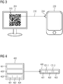
- Fig. 2 shows a monitored device 200 together with a mobile monitoring unit 220 and a central data acquisition unit 240.
- the monitored device here comprises an interface 201, a first computing unit 202, a first storage unit 203 and an output unit 204.
- the mobile monitoring unit 220 comprises an interface 221, a second computing unit 222, a second memory unit 223 and an input unit 224.
- the output unit 204 of the monitored device 200 is connected to the input unit 224 of the mobile monitoring unit 220 via an optical channel 210.
- the mobile monitoring unit 220 is connected to the central data acquisition unit 240 via a network 230.
- the monitored device 200 can in particular comprise a computer, a microcontroller or an integrated circuit which comprises the interface 201, the first computing unit 202, the first storage unit 203 and / or the first output unit 204.
- a mobile monitoring unit 220 can also be, in particular, a computer, a microcontroller or an integrated circuit.
- a mobile monitoring unit 220 can in particular be a mobile phone, in particular a smartphone.
- An interface 201, 221 can be a hardware or software interface (for example PCI bus, USB or Firewire).
- a first processing unit 202 and a second processing unit 222 can have hardware elements or software elements, for example a microprocessor or a so-called FPGA (English acronym for “Field Programmable Gate Array”).
- a first storage unit 203 and a second storage unit 223 can be implemented as a non-permanent main memory (random access memory, or RAM for short) or as a permanent mass storage device (hard drive, USB stick, SD card, solid-date disc).
- An output unit 204 can in particular be a screen, but it can alternatively also be a printer.
- An input unit 224 is, in particular, a camera. But it can also be a keyboard, a mouse or a scanner.
- a network 230 can be an intranet or, in particular, the Internet.
- a central data acquisition unit for 240 can in particular be implemented by a database; the central data acquisition unit 240 can furthermore comprise a processing unit for data management.
- the input unit 224 of the mobile monitoring unit 220 is designed to receive the output unit 204 of the Monitored device 200 is displayed to capture visual information 420.
- the visual information 420 is transmitted via an optical medium 210, the optical medium here being the ambient air.
- the visual information 420 can be represented or encoded in particular by means of an image, in particular by means of a QR code 500 or a bar code 600.
- the output unit 204 is a screen
- the input unit 224 can act as a camera be designed that can accommodate a QR code 500 displayed on the screen.
- the output unit 204 is a printer that prints the visual information 420 on paper
- the input unit 224 can likewise be a camera or a scanner.
- Fig. 3 shows an output unit 204 of a monitored device 200 and an input unit 224 of a mobile monitoring unit 220 in the first embodiment.
- the output unit 204 is here a screen or monitor of the mobile ultrasound unit, which is designed to display a QR code 500.
- the mobile monitoring unit 220 is designed as a mobile phone, in particular as a smartphone, and its input unit 224 as a camera, in particular as a photo camera, which is designed to capture a QR code 500.
- the optical transmission medium 210 is formed here by the ambient air.
- the mobile phone can communicate with the network 230 (here the Internet) and thus with the central data acquisition unit 240 via a cellular network or via a wireless network (for example WLAN).
- Fig. 4 shows the first data record 400 as well as associated visual information 420 in the first exemplary embodiment.
- the first data record 400 comprises public device information 401, configuration information 402 and a hash value 403.
- the hash value 403 was determined by using a hash function, the hash function being based on a combination the public device information 401, the configuration information 402 and a secret device information 404 was applied.
- the public device information 401 is a serial number
- the configuration information 402 is a software version number
- the secret device information 404 is a secret serial number.
- the combination of the public device information 401, the configuration information 402 and the secret device information 404 takes place in such a way that the information is converted into a character string and the character strings are linked.
- the hash function is then applied to the linked string.
- the visual information 420 also includes the public device information 401, the configuration information 402 and the hash value 403, as well as separators 421.1, 421.2. This information is linked one after the other as character strings.
- the resulting character string can optionally be encoded as QR code 500 or barcode 600, but other encodings are also possible.
- http denotes the scheme used in the URL
- example.com the host of the URL, which here corresponds to the address of the central data acquisition unit 240
- verify.php denotes the path of the URL
- Fig. 5 shows a QR code 500.
- the QR code 500 consists of first areas 501.1, 501.2 in black and second areas 502.1, 502.2 in white.
- the first areas 501.1, 501.2 are a collection of black pixels
- the second areas 502.1, 502.2 are a collection of white pixels.
- the pixels of the QR code 500 are arranged in a grid structure.
- the QR code 500 comprises position marks 503 in the form of a geometric arrangement of white and black pixels, a QR code 500 can also contain further marks or patterns that enable the QR code 500 to be detected and / or the QR code to be decoded 500 facilitate.
- the information in the QR code 500 is contained in the geometric shape of the first areas 501.1, 501.2 and the second areas 502.1, 502.2.
- the geometric shape of the first areas 501.1, 501.2 and of the second areas 502.1, 502.2 is given in this exemplary embodiment, contiguous square pixels in a grid.
- a QR code 500 can contain redundant information. This redundant information can in particular be used to compensate for errors in the display or in the acquisition of QR codes 500. Different levels of redundancy are possible, in particular more than 7% redundant content, in particular more than 15% redundant content, in particular more than 25% redundant content, in particular more than 30% redundant content.
- a content of the QR code 500 is called redundant if the visual information 420 contained in the QR code 500 can also be determined without this content.
- the Reed-Solomon coding is known for implementing the error correction.
- Fig. 6 shows a bar code 600.
- the bar code consists of black bars 601.1, 601.2 and white bars 602.1 and 602.2.
- the information encoded in the barcode 600 is contained in the different thicknesses of the bars 601.1, 601.2, 602.1 and 602.2.
- the bar code 600 can also contain redundant information so that an error correction when the bar code 600 is detected is possible. In particular it is known to use certification marks.
Landscapes
- Engineering & Computer Science (AREA)
- Physics & Mathematics (AREA)
- Health & Medical Sciences (AREA)
- Electromagnetism (AREA)
- General Health & Medical Sciences (AREA)
- General Physics & Mathematics (AREA)
- Toxicology (AREA)
- Theoretical Computer Science (AREA)
- Computer Vision & Pattern Recognition (AREA)
- Artificial Intelligence (AREA)
- Biomedical Technology (AREA)
- General Business, Economics & Management (AREA)
- Business, Economics & Management (AREA)
- Epidemiology (AREA)
- Public Health (AREA)
- Primary Health Care (AREA)
- Medical Informatics (AREA)
- Information Transfer Between Computers (AREA)
- Measuring And Recording Apparatus For Diagnosis (AREA)
- Management, Administration, Business Operations System, And Electronic Commerce (AREA)
- Information Retrieval, Db Structures And Fs Structures Therefor (AREA)
- Telephonic Communication Services (AREA)
Description
In vielen Bereichen der Technik ist es notwendig, Informationen über eine beim Kunden installierte Vorrichtung zentral beim Hersteller der Vorrichtung oder bei einem Dienstleistungsanbieter in einer Datenbank zu speichern. Solche Datenbanken können einerseits notwendig sein, um regulatorischen Anforderungen zu genügen, andererseits können sie aber auch zur Verbesserung von erbrachten Dienstleistungen verwendet werden. Von besonderer Bedeutung ist hierbei, die derzeitige Konfiguration der Vorrichtung, umfassend die verbauten körperlichen Komponenten (die sog. "Hardware") und die verwendete Steueranweisungen (die sog. "Software"), oder den aktuellen Zustand oder Status der Vorrichtung zu speichern. Eine solche Konfiguration kann sich aber in der Gebrauchszeit der Vorrichtung ändern. Um stets die aktuelle Konfiguration der Vorrichtung zu speichern, muss die Vorrichtung daher überwacht werden.In many areas of technology, it is necessary to store information about a device installed at the customer's facility centrally at the manufacturer of the device or at a service provider in a database. Such databases can be necessary on the one hand to meet regulatory requirements, but on the other hand they can also be used to improve the services provided. It is of particular importance here to save the current configuration of the device, including the built-in physical components (the so-called "hardware") and the control instructions used (the so-called "software"), or the current state or status of the device. However, such a configuration can change over the period of use of the device. In order to always save the current configuration of the device, the device must therefore be monitored.
Bei derartigen zu überwachenden Vorrichtungen handelt es sich um medizintechnische Anlagen, beispielsweise um Ultraschallgeräte oder um fahrbare Röntgengeräte, für die regelmäßig besonders strenge regulatorische Anforderungen gelten.Such devices to be monitored are medical-technical systems, for example ultrasound devices or mobile X-ray devices, for which particularly strict regulatory requirements regularly apply.
Insbesondere aus Kostengründen ist es möglich, dass auch der Benutzer einer Vorrichtung selbst auf Anweisung beispielsweise des Herstellers Änderungen an der Konfiguration der Vorrichtung durch Hard- und/oder Softwareupdates durchführt. Der Erfolg oder Misserfolg dieser Konfigurationsänderungen müssen dann dem Hersteller der Vorrichtung oder einem Dienstleistungsanbieter zur Kenntnis gebracht werden. Auch müssen Informationen über Änderung von Zuständen (z.B. das Auftreten eines Fehlerzustands) an den Hersteller der Vorrichtung oder den Dienstleistungsanbieter gesendet werden.For reasons of cost, in particular, it is possible for the user of a device to carry out changes to the configuration of the device himself by means of hardware and / or software updates, for example on the instructions of the manufacturer. The success or failure of these configuration changes must then be brought to the attention of the device manufacturer or a service provider. Information about changes in states (for example the occurrence of an error state) must also be sent to the manufacturer of the device or the service provider.
Hierzu ist es bekannt, die überwachte Vorrichtung mit dem Internet zu verbinden, sodass die überwachte Vorrichtung eine Rückmeldung über den Erfolg oder den Misserfolg der Konfigurationsänderung geben kann. Wegen Sicherheitsbedenken, regulatorischen Anforderungen oder aus Kostengründen gibt es aber Vorrichtungen, die nicht mit dem Internet verbunden sind, beispielsweise mobile Ultraschallgeräte. Bei solchen, insbesondere bei mobilen Vorrichtungen, ist eine Rückmeldung über das Internet daher nicht möglich.To this end, it is known to connect the monitored device to the Internet so that the monitored device can provide feedback on the success or failure of the configuration change. Because of security concerns, regulatory requirements or for cost reasons, however, there are devices that are not connected to the Internet, for example mobile ultrasound devices. With such devices, especially with mobile devices, feedback via the Internet is therefore not possible.
Weiterhin ist es bekannt, dass Anwender der Vorrichtung eine Rückmeldung über die erfolgte Konfigurationsänderung an den Hersteller der Vorrichtung oder den Dienstleistungsanbieter übermitteln, beispielsweise über Telefon, Fax oder E-Mail, und dabei die Daten der Konfigurationsänderung manuell und in einem vorgegebenen oder frei gewähltem Format erfassen. Eine solche Rückmeldung ist aber zeitintensiv und damit mit Kosten verbunden. Weiterhin können durch Übertragungsfehler oder durch absichtliche Manipulation des Anwenders falsche Informationen beim Hersteller der Vorrichtung oder beim Dienstleistungsanbieter gespeichert werden.It is also known that users of the device transmit feedback on the configuration change to the manufacturer of the device or the service provider, for example via telephone, fax or e-mail, and thereby transmit the data of the configuration change manually and in a predefined or freely selected format capture. Such feedback is time-consuming and therefore associated with costs. Furthermore, incorrect information can be stored by the manufacturer of the device or by the service provider due to transmission errors or deliberate manipulation by the user.
Aus der Druckschrift
Es ist daher die Aufgabe der vorliegenden Erfindung, eine schnelle, kostengünstige und manipulationssichere Methode bereitzustellen, den Erfolg einer Konfigurationsänderung an eine zentrale Datenerfassungseinheit zu übertragen.It is therefore the object of the present invention to provide a fast, inexpensive and tamper-proof method for transferring the success of a configuration change to a central data acquisition unit.
Die Aufgabe wird gelöst durch ein Verfahren nach Anspruch 1, ein Datenübertragungssystem nach Anspruch 13, ein Computerprogrammprodukt nach Anspruch 15 sowie durch ein computerlesbares Speichermedium nach Anspruch 16.The object is achieved by a method according to
Nachstehend wird die erfindungsgemäße Lösung der Aufgabe sowohl in Bezug auf die beanspruchten Vorrichtungen als auch in Bezug auf das beanspruchte Verfahren beschrieben. Hierbei erwähnte Merkmale, Vorteile oder alternative Ausführungsformen sind ebenso auch auf die anderen beanspruchten Gegenstände zu übertragen und umgekehrt. Mit anderen Worten können die gegenständlichen Ansprüche (die beispielsweise auf eine Vorrichtung gerichtet sind) auch mit den Merkmalen, die in Zusammenhang mit einem Verfahren beschrieben oder beansprucht sind, weitergebildet sein. Die entsprechenden funktionalen Merkmale des Verfahrens werden dabei durch entsprechende gegenständliche Module ausgebildet.The solution to the problem according to the invention is described below both in relation to the claimed devices and in relation to the claimed method. Features, advantages or alternative embodiments mentioned here are also to be transferred to the other claimed subjects and vice versa. In other words, the present claims (which are directed, for example, to a device) can also be developed with the features that are described or claimed in connection with a method. The corresponding functional features of the method are formed by corresponding objective modules.
Die Erfindung basiert darauf, dass eine Konfigurationsänderung an einer überwachten Vorrichtung mittels einer ersten Recheneinheit einer überwachten Vorrichtung festgestellt wird. Weiterhin wird ein erster Datensatz mittels der ersten Recheneinheit der überwachten Vorrichtung bestimmt, wobei der erste Datensatz wenigstens eine öffentliche Geräteinformation und eine Konfigurationsinformation umfasst, und wobei die öffentliche Geräteinformation der überwachten Vorrichtung eineindeutig zuordenbar ist. Weiterhin wird eine visuelle Information basierend auf dem ersten Datensatz mittels der ersten Recheneinheit der überwachten Vorrichtung bestimmt. Weiterhin wird die visuelle Information von einer Ausgabeeinheit der überwachten Vorrichtung zu einer Eingabeeinheit einer mobilen Überwachungseinheit optisch übertragen. Weiterhin wird ein zweiter Datensatz aus der visuellen Information mittels einer zweiten Recheneinheit der mobilen Überwachungseinheit bestimmt, wobei aus dem zweiten Datensatz wenigstens die öffentliche Geräteinformation und die Konfigurationsinformation bestimmbar sind. Weiterhin wird der zweite Datensatz von einer Schnittstelle der mobilen Überwachungseinheit zu einer zentralen Datenerfassungseinheit übertragen. Hierbei kann die überwachte Vorrichtung insbesondere eine medizinische Vorrichtung sein, insbesondere ein bildgebendes Gerät, insbesondere ein mobiles Ultraschallgerät oder ein mobiles C-Bogen-Röntgengerät.The invention is based on the fact that a configuration change on a monitored device is determined by means of a first processing unit of a monitored device. Furthermore, a first data set is determined by means of the first processing unit of the monitored device, the first data set comprising at least one piece of public device information and one piece of configuration information, and wherein the public device information can be uniquely assigned to the monitored device. Furthermore, visual information is determined based on the first data record by means of the first computing unit of the monitored device. Furthermore, the visual information is optically transmitted from an output unit of the monitored device to an input unit of a mobile monitoring unit. Furthermore, a second data record is determined from the visual information by means of a second processing unit of the mobile monitoring unit, with at least the public device information and the configuration information being able to be determined from the second data record. Furthermore, the second data record is transmitted from an interface of the mobile monitoring unit to a central data acquisition unit. Here, the monitored device can in particular be a medical device, in particular an imaging device, in particular a mobile ultrasound device or a mobile C-arm X-ray device.
Die Erfinder haben erkannt, dass durch die Übertragung der öffentlichen Geräteinformation und der Konfigurationsinformation zu einer mobilen Überwachungseinheit eine Verbindung der mobilen Überwachungseinheit zur zentralen Datenerfassungseinheit, beispielsweise über das Internet, verwendet werden kann. Daher muss die überwachte Vorrichtung nicht direkt mit der zentralen Datenerfassungseinheit verbunden sein, dies führt zu einer Kostenersparnis und zu einer besseren Sicherheit der überwachten Vorrichtung. Weiterhin ist es durch die Verwendung einer optischen Übertragung nicht notwendig, eine dauerhafte Verbindung, beispielsweise eine kabelgebundene Verbindung oder eine Funkverbindung, zwischen der überwachten Vorrichtung und der mobilen Überwachungseinheit herzustellen. Die mobile Überwachungseinheit kann daher zum einen insbesondere zum Überwachen von mehreren überwachten Vorrichtungen verwendet werden, dies stellt eine Kostenersparnis dar. Durch die Verwendung der optischen Übertragung kann weiterhin die überwachte Vorrichtung nicht durch einen Dritten manipuliert werden, da keine Informationen und insbesondere kein Schadcode an die überwachte Vorrichtung übertragen werden kann. Durch das optische Übertragen ist es weiterhin nicht notwendig, die öffentliche Geräteinformation und die Konfigurationsinformation manuell zu erfassen oder weiterzugeben, sodass der Datensatz besonders schnell und effizient zu der zentralen Datenerfassungseinheit übertragen werden kann, zudem werden Flüchtigkeitsfehler des Anwenders beim Erfassen der Daten vermieden.The inventors have recognized that by transmitting the public device information and the configuration information to a mobile monitoring unit, a connection from the mobile monitoring unit to the central data acquisition unit, for example via the Internet, can be used. Therefore, the monitored device does not have to be connected directly to the central data acquisition unit, this leads to cost savings and better security of the monitored device. Furthermore, by using an optical transmission, it is not necessary to establish a permanent connection, for example a wired connection or a radio connection, between the monitored device and the mobile monitoring unit. The mobile monitoring unit can therefore be used, on the one hand, in particular for monitoring several monitored devices; this represents a cost saving. By using the optical transmission, the monitored device cannot be manipulated by a third party, since no information and in particular no malicious code is transmitted to the monitored device can be transmitted. Due to the optical transmission, it is also not necessary to manually record or pass on the public device information and the configuration information, so that the data record can be transmitted particularly quickly and efficiently to the central data recording unit, and careless mistakes by the user when recording the data are avoided.
Nach einem weiteren Aspekt der Erfindung umfasst die Konfigurationsinformation wenigstens eine Information über den Erfolg der Konfigurationsänderung an der überwachten Vorrichtung. Der Erfolg einer Konfigurationsänderung ist insbesondere gegeben, wenn die Konfigurationsänderung erfolgreich durchgeführt wurde. Insbesondere ist es möglich, die visuelle Information nur darzustellen, wenn die Konfigurationsänderung der überwachten Vorrichtung erfolgreich war. Die Erfinder haben erkannt, dass mit einer derartigen Konfigurationsinformation besonders einfach ein korrekter Datenbestand in der zentralen Datenerfassungseinheit erreicht werden kann.According to a further aspect of the invention, the configuration information includes at least one item of information about the success of the configuration change on the monitored device. A configuration change is particularly successful if the configuration change has been carried out successfully. In particular, it is possible to display the visual information only if the configuration change of the monitored device was successful. The inventors have recognized that with such configuration information a correct database can be achieved in the central data acquisition unit in a particularly simple manner.
Nach einem weiteren Aspekt der Erfindung ist die visuelle Information in einem Bild enthalten, wobei beim optischen ersten Übertragen das Bild auf der Ausgabeeinheit der überwachten Anlage dargestellt wird und das Bild von der Eingabeeinheit der mobilen Überwachungseinheit erfasst wird. Eine visuelle Information ist insbesondere in einem Bild enthalten, wenn sie aus dem Bild alleine wiederhergestellt oder rekonstruiert werden kann. Eine visuelle Information ist insbesondere auch dann in einem Bild enthalten, wenn die visuelle Information in einer verschlüsselten oder codierten Form im Bild enthalten ist. Die Erfinder haben erkannt, dass das Ausgeben eines Bildes auf der Ausgabeeinheit der überwachten Vorrichtung sowie das Erfassen des Bildes mit der Eingabeeinheit der mobilen Überwachungseinheit besonders kostengünstig und effizient ist, da die geeignete Ausgabeeinheit und die geeignete Eingabeeinheit im Regelfall bereits vorhanden und für das Anzeigen oder Erfassen eines Bildes ausgebildet sind, und daher das Verfahren ohne kostenintensive Modifikation der überwachten Vorrichtung oder der mobilen Überwachungseinheit durchgeführt werden kann.According to a further aspect of the invention, the visual information is contained in an image, with the image being displayed on the output unit of the monitored system during the first optical transmission and the image being captured by the input unit of the mobile monitoring unit. Visual information is contained in an image in particular if it can be restored or reconstructed from the image alone. In particular, visual information is also contained in an image if the visual information is contained in the image in an encrypted or encoded form. The inventors have recognized that outputting an image on the output unit of the monitored device as well as capturing the image with the input unit of the mobile monitoring unit is particularly cost-effective and efficient, since the suitable output unit and the suitable input unit are usually already available and for displaying or Acquisition of an image are formed, and therefore the method can be carried out without costly modification of the monitored device or the mobile monitoring unit.
Nach einem weiteren Aspekt der Erfindung umfasst das Bild Bildbereiche, wobei ein Bildbereich entweder eine erste Farbe oder eine zweite Farbe aufweist, und wobei sich die erste Farbe und die zweite Farbe zumindest in ihrer Helligkeit und/oder in ihrem Farbton unterscheiden. Die erste Farbe und die zweite Farbe können sich auch insbesondere in ihrer Helligkeit unterscheiden. Die Erfinder haben erkannt, dass durch derartige Bildbereiche eine visuelle Information besonders effizient übertragen werden kann.According to a further aspect of the invention, the image comprises image areas, wherein an image area has either a first color or a second color, and wherein the first color and the second color differ at least in their brightness and / or in their hue. The first color and the second color can also differ in particular in terms of their brightness. The inventors have recognized that visual information can be transmitted particularly efficiently through such image areas.
Nach einem weiteren Aspekt der Erfindung ist die visuelle Information in der geometrischen Anordnung der Bildbereiche des Bildes enthalten. Die Erfinder haben erkannt, dass diese geometrische Anordnung besonders gut, schnell und mit besonders wenigen Fehlern von der Eingabeeinheit der mobilen Überwachungseinheit erkannt werden kann.According to a further aspect of the invention, the visual information is contained in the geometric arrangement of the image areas of the image. The inventors have recognized that this geometric arrangement is particularly good, fast and with special few errors can be recognized by the input unit of the mobile monitoring unit.
Nach einem weiteren Aspekt der Erfindung umfasst das Bild einen eindimensionalen Barcode oder einen zweidimensionalen Barcode. Bei einem eindimensionalen Barcode kann es sich insbesondere um einen Strichcode handeln, bei einem zweidimensionalen Barcode kann es sich insbesondere um einen gestapelten Strichcode, einen Matrixcode oder eine Punktcode handeln. Bei einem zweidimensionalen Barcode kann es sich insbesondere um einen "Quick Response Code" (kurz "QR-Code", ein deutscher Begriff ist Schnellantwortcode) handeln. Ein eindimensionaler Barcode oder ein zweidimensionaler Barcode können insbesondere redundante Bereiche umfassen. Die Erfinder haben erkannt, dass sich durch einen eindimensionalen Barcode oder einen zweidimensionalen Barcode besonders effizient Informationen übertragen lassen. Weiterhin umfassen eindimensionale Barcodes und zweidimensionale Barcodes redundante Bereiche, sodass Fehler bei der Übertragung verhindert werden. Gleichzeitig wird durch die redundanten Bereiche auch die optische Übertragung beschleunigt, da Ungenauigkeiten in der Positionierung und der Bilderfassung durch die mobile Überwachungseinheit durch die Fehlerredundanz ausgeglichen werden können.According to a further aspect of the invention, the image comprises a one-dimensional bar code or a two-dimensional bar code. A one-dimensional bar code can in particular be a bar code, and a two-dimensional bar code can in particular be a stacked bar code, a matrix code or a point code. A two-dimensional barcode can in particular be a "Quick Response Code" ("QR code" for short, a German term is a quick response code). A one-dimensional barcode or a two-dimensional barcode can in particular include redundant areas. The inventors have recognized that information can be transmitted particularly efficiently using a one-dimensional barcode or a two-dimensional barcode. Furthermore, one-dimensional barcodes and two-dimensional barcodes include redundant areas, so that errors during transmission are prevented. At the same time, the redundant areas also accelerate the optical transmission, since inaccuracies in positioning and image acquisition by the mobile monitoring unit can be compensated for by the error redundancy.
Nach einem weiteren Aspekt der Erfindung umfasst die öffentliche Geräteinformation eine erste Identifikationsnummer der überwachten Vorrichtung. Bei einer ersten Identifikationsnummer kann es sich insbesondere um eine Seriennummer der überwachten Vorrichtung handeln. Eine Identifikationsnummer kann insbesondere auch Zeichen umfassen, die nicht numerisch sind, beispielsweise Buchstaben oder Sonderzeichen. Die Erfinder haben erkannt, dass durch die Verwendung einer ersten Identifikationsnummer die an die zentrale Datenerfassungseinheit übertragenen Daten besonders einfach und damit schnell der überwachten Vorrichtung zugeordnet werden können.According to a further aspect of the invention, the public device information comprises a first identification number of the monitored device. A first identification number can in particular be a serial number of the monitored device. An identification number can in particular also include characters that are not numeric, for example letters or special characters. The inventors have recognized that through the use of a first identification number, the data transmitted to the central data acquisition unit can be assigned to the monitored device particularly easily and thus quickly.
Nach einem weiteren Aspekt der Erfindung umfasst die Konfigurationsänderung das Installieren und/oder das Entfernen einer Hardware- und/oder Softwarekomponente, wobei die Konfigurationsinformation eine zweite Identifikationsnummer der Hardware- und/oder Softwarekomponente umfasst. Die Erfinder haben erkannt, dass durch eine derartige Konfigurationsinformation besonders schnell und effizient die geänderte Konfiguration der überwachten Vorrichtung beschrieben werden kann. Insbesondere kann beim Vorhandensein mehrerer gleichwertiger Hard- und/oder Softwarekomponenten festgestellt werden, welche dieser Komponenten in welcher der überwachten Vorrichtungen verwendet wird.According to a further aspect of the invention, the configuration change comprises installing and / or removing a Hardware and / or software component, wherein the configuration information includes a second identification number of the hardware and / or software component. The inventors have recognized that the changed configuration of the monitored device can be described particularly quickly and efficiently by means of such configuration information. In particular, if several equivalent hardware and / or software components are present, it can be determined which of these components is used in which of the monitored devices.
Nach einem weiteren Aspekt der Erfindung ist die visuelle Information derart ausgebildet, dass eine Veränderung der Konfigurationsinformation und der öffentlichen Geräteinformation mittels der mobilen Überwachungseinheit und/oder mittels der zentralen Datenerfassungseinheit feststellbar ist. Die Erfinder haben erkannt, dass derart Übertragungsfehler oder absichtliche Manipulationen der Daten ausgeschlossen sind. Hierdurch kann die Konfigurationsinformation insbesondere fehlerfrei in der zentralen Datenerfassungseinheit gespeichert werden.According to a further aspect of the invention, the visual information is designed in such a way that a change in the configuration information and the public device information can be determined by means of the mobile monitoring unit and / or by means of the central data acquisition unit. The inventors have recognized that such transmission errors or deliberate manipulation of the data are excluded. As a result, the configuration information can in particular be stored in the central data acquisition unit without errors.
Nach einem weiteren Aspekt der Erfindung umfasst die visuelle Information wenigstens das Ergebnis der Anwendung einer Einwegstreuwertfunktion auf den ersten Datensatz. Ein englischer Fachbegriff für Einwegstreuwertfunktion ist "Hashfunktion". Die Erfinder haben erkannt, dass durch die Verwendung einer Einwegstreuwertfunktion besonders schnell die Veränderung der Konfigurationsinformation und der öffentlichen Geräteinformation festgestellt werden kann, weiterhin ist das Ergebnis der Anwendung einer üblichen Einwegstreufunktion kurz und daher schnell und kostengünstig zu übertragen.According to a further aspect of the invention, the visual information comprises at least the result of applying a one-way scatter value function to the first data set. A technical term for one-way scatter function is "hash function". The inventors have recognized that by using a one-way scatter function, the change in the configuration information and the public device information can be determined particularly quickly; furthermore, the result of using a conventional one-way scatter function is short and can therefore be transmitted quickly and inexpensively.
Nach einem weiteren Aspekt der Erfindung umfasst der erste Datensatz weiterhin eine geheime Geräteinformation, wobei die geheime Geräteinformation der überwachten Vorrichtung eineindeutig zuordenbar ist, und wobei die geheime Geräteinformation nicht aus der visuellen Information bestimmbar ist. Die Erfinder haben erkannt, dass durch die Verwendung einer geheimen Geräteinformation eine Manipulation der übertragenen Daten ausgeschlossen werden kann.According to a further aspect of the invention, the first data record further comprises secret device information, the secret device information being uniquely assignable to the monitored device, and the secret device information not being determinable from the visual information. the The inventors have recognized that manipulation of the transmitted data can be ruled out by using secret device information.
Nach einem weiteren möglichen Aspekt der Erfindung ist die geheime Geräteinformation sowohl in der zentralen Datenerfassungseinheit als auch in der überwachten Vorrichtung gespeichert. Die Erfinder haben erkannt, dass durch eine derartige Speicherung eine Manipulation besonders einfach und kostengünstig ausgeschlossen werden kann.According to a further possible aspect of the invention, the secret device information is stored both in the central data acquisition unit and in the monitored device. The inventors have recognized that manipulation can be excluded in a particularly simple and inexpensive manner by means of such storage.
Nach einem weiteren möglichen Aspekt der Erfindung umfasst die Konfigurationsänderung das Installieren und/oder das Entfernen einer Hardware- und/oder Softwarekomponente, weiterhin ist die geheime Geräteinformation sowohl in der zentralen Datenerfassungseinheit als auch in der Hardware- und/oder Softwarekomponente gespeichert. Die Erfinder haben erkannt, dass durch eine derartige Speicherung die Manipulation besonders gut ausgeschlossen werden kann, da für unterschiedliche Konfigurationsänderungen jeweils unterschiedliche geheime Geräteinformationen gewählt werden können.According to a further possible aspect of the invention, the configuration change includes installing and / or removing a hardware and / or software component; the secret device information is also stored both in the central data acquisition unit and in the hardware and / or software component. The inventors have recognized that such storage can be particularly effective in preventing manipulation, since different secret device information can be selected for different configuration changes.
Nach einem weiteren Aspekt der Erfindung ist die zweite Identifikationsnummer der überwachten Vorrichtung eineindeutig zuordenbar, wobei die zweite Identifikationsnummer sowohl in der zentralen Datenerfassungseinheit als auch in der neuen Hardware- und/oder Softwarekomponente gespeichert ist, und wobei die zweite Identifikationsnummer nicht aus der visuellen Information bestimmbar ist. Die Erfinder haben erkannt, dass durch eine derartige zweite Identifikationsnummer Manipulationssicherheit garantiert werden kann, ohne zusätzliche Informationen in der überwachten Vorrichtung zu speichern.According to a further aspect of the invention, the second identification number of the monitored device can be uniquely assigned, with the second identification number being stored both in the central data acquisition unit and in the new hardware and / or software component, and with the second identification number not being determinable from the visual information is. The inventors have recognized that security against manipulation can be guaranteed by means of such a second identification number without storing additional information in the monitored device.
Nach einem weiteren Aspekt der Erfindung ist der zweite Datensatz ein Abfrageteil eines einheitlichen Ressourcenzeigers, wobei das zweite Übertragen den Aufruf des einheitlichen Ressourcenzeigers umfasst. Ein englischer Fachbegriff für einen einheitlichen Ressourcenzeigers ist "Uniform Ressource Locator", kurz "URL". Ein englischer Fachbegriff für den Abfrageteil eines einheitlichen Ressourcenzeigers ist "Query". Ein einheitlicher Ressourcenzeiger kann insbesondere ein elektronischer Verweis sein. Ein englischer Fachbegriff für einen elektronischen Verweis ist "Hyperlink". Das zweite Übertragen kann dann durch das Aufrufen des Hyperlinks durchgeführt werden, wobei der Abfrageteil an das Ziel des Aufrufs übertragen wird. Die Erfinder haben erkannt, dass durch die Verwendung eines einheitlichen Ressourcenzeigers bestehende Kommunikationsinfrastruktur verwendet werden kann. Bei dieser Kommunikationsinfrastruktur kann es sich beispielsweise um das Internet handeln. Es ist daher nicht notwendig, eine kostenintensive eigene Kommunikationsinfrastruktur aufzubauen und/oder vorzuhalten.According to a further aspect of the invention, the second data record is a query part of a uniform resource pointer, the second transmission comprising calling up the uniform resource pointer. An English technical term for a uniform resource pointer is "Uniform Resource Locator "," URL "for short. An English technical term for the query part of a uniform resource pointer is" Query ". A uniform resource pointer can in particular be an electronic reference. An English technical term for an electronic reference is" Hyperlink ". The second transmission can then be through the call of the hyperlink can be carried out, the query part being transmitted to the destination of the call. The inventors have recognized that existing communication infrastructure can be used by using a uniform resource pointer. This communication infrastructure can be the Internet, for example therefore it is not necessary to set up and / or maintain a cost-intensive communication infrastructure of your own.
Die Erfindung kann weiterhin eine überwachte Vorrichtung betreffen, ausgebildet zum Übertragen eines Datensatzes, umfassend folgende Einheiten:
- Erste Recheneinheit, ausgebildet zum Feststellen einer Konfigurationsänderung an der überwachten Vorrichtung, weiterhin ausgebildet zum ersten Bestimmen eines ersten Datensatzes, wobei der erste Datensatz wenigstens eine öffentliche Geräteinformation und eine Konfigurationsinformation umfasst, und wobei die öffentliche Geräteinformation der überwachten Vorrichtung eineindeutig zuordenbar ist, weiterhin ausgebildet zum zweiten Bestimmen einer visuellen Information basierend auf dem ersten Datensatz,
- Ausgabeeinheit, ausgebildet zum optischen ersten Übertragen der visuellen Information zu einer Eingabeeinheit einer mobilen Überwachungseinheit.
- First computing unit, designed to determine a configuration change on the monitored device, further designed to first determine a first data set, wherein the first data set comprises at least one piece of public device information and one piece of configuration information, and wherein the public device information can be uniquely assigned to the monitored device, further designed to second determination of visual information based on the first data set,
- Output unit designed for the optical first transmission of the visual information to an input unit of a mobile monitoring unit.
Eine solche überwachte Vorrichtung kann insbesondere dazu ausgebildet sein, die zuvor beschriebenen erfindungsgemäßen Verfahren und ihre Aspekte auszuführen. Die überwachte Vorrichtung ist dazu ausgebildet, diese Verfahren und ihre Aspekte auszuführen, indem die erste Recheneinheit und die Ausgabeeinheit dazu ausgebildet sind, die entsprechenden Verfahrensschritte auszuführen.Such a monitored device can in particular be designed to carry out the above-described methods according to the invention and their aspects. The monitored device is designed to carry out these methods and their aspects in that the first processing unit and the output unit are designed to carry out the corresponding method steps.
Die Erfindung betrifft weiterhin ein Datenübertragungssystem, ausgebildet zum Übertragen eines Datensatzes, umfassend folgende Vorrichtungen:
- a) Überwachte Vorrichtung, umfassend folgende Einheiten:
- Erste Recheneinheit, ausgebildet zum Feststellen einer Konfigurationsänderung an der überwachten Vorrichtung, weiterhin ausgebildet zum ersten Bestimmen eines ersten Datensatzes, wobei der erste Datensatz wenigstens eine öffentliche Geräteinformation und eine Konfigurationsinformation umfasst, und wobei die öffentliche Geräteinformation der überwachten Vorrichtung eineindeutig zuordenbar ist, weiterhin ausgebildet zum zweiten Bestimmen einer visuellen Information basierend auf dem ersten Datensatz,
- Ausgabeeinheit, ausgebildet zum optischen ersten Übertragen der visuellen Information zu einer Eingabeeinheit einer mobilen Überwachungseinheit,
- b) Mobile Überwachungseinheit, umfassend folgende Einheiten:
- Eingabeeinheit, ausgebildet zum optischen ersten Empfangen der visuellen Information von der Ausgabeeinheit der überwachten Vorrichtung,
- Zweite Recheneinheit, ausgebildet zum dritten Bestimmen eines zweiten Datensatzes aus der visuellen Information mittels einer zweiten Recheneinheit der mobilen Überwachungseinheit, wobei aus dem zweiten Datensatz wenigstens die öffentliche Geräteinformation und die Konfigurationsinformation bestimmbar sind,
- Schnittstelle, ausgebildet zum zweiten Übertragen des zweiten Datensatzes zu einer zentralen Datenerfassungseinheit.
- a) Monitored device, comprising the following units:
- First computing unit, designed to determine a configuration change on the monitored device, further designed to first determine a first data set, wherein the first data set comprises at least one piece of public device information and one piece of configuration information, and wherein the public device information can be uniquely assigned to the monitored device, further designed to second determination of visual information based on the first data set,
- Output unit designed for the optical first transmission of the visual information to an input unit of a mobile monitoring unit,
- b) Mobile monitoring unit, comprising the following units:
- Input unit, designed for the optical first reception of the visual information from the output unit of the monitored device,
- Second computing unit, designed for the third determination of a second data set from the visual information by means of a second computing unit of the mobile monitoring unit, with at least the public device information and the configuration information being determinable from the second data set,
- Interface designed for the second transmission of the second data set to a central data acquisition unit.
Ein solches Datenübertragungssystem kann insbesondere dazu ausgebildet sein, die zuvor beschriebenen erfindungsgemäßen Verfahren und ihre Aspekte auszuführen. Das Datenübertragungssystem ist dazu ausgebildet, diese Verfahren und ihre Aspekte auszuführen, indem die überwachte Vorrichtung und ihre zugehörigen Einheiten sowie die mobile Überwachungseinheit und ihre zugehörigen Einheiten dazu ausgebildet sind, die entsprechenden Verfahrensschritte auszuführen.Such a data transmission system can in particular be designed to carry out the previously described methods according to the invention and their aspects. The data transmission system is designed to carry out these methods and their aspects in that the monitored device and its associated units and the mobile monitoring unit and its associated units are designed to carry out the corresponding method steps.
Die Erfindung kann auch ein Computerprogrammprodukt mit einem Computerprogramm sowie ein computerlesbares Medium für eine überwachte Vorrichtung oder für ein Datenübertragungssystem betreffen. Eine weitgehend softwaremäßige Realisierung hat den Vorteil, dass auch schon bisher verwendete überwachte Vorrichtungen oder Datenübertragungssystem auf einfache Weise durch ein Software-Update nachgerüstet werden können, um auf die erfindungsgemäße Weise zu arbeiten. Ein solches Computerprogrammprodukt kann neben dem Computerprogramm gegebenenfalls zusätzliche Bestandteile wie z. B. eine Dokumentation und/oder zusätzliche Komponenten sowie Hardwarekomponenten wie z. B. Hardwareschlüssel (Dongels etc.) zur Nutzung der Software umfassen.The invention can also relate to a computer program product with a computer program and a computer-readable medium for a monitored device or for a data transmission system. A largely software-based implementation has the advantage that monitored devices or data transmission systems that have already been used can be easily retrofitted with a software update in order to work in the manner according to the invention. In addition to the computer program, such a computer program product can optionally contain additional components such as B. a documentation and / or additional components and hardware components such. B. include hardware keys (dongels, etc.) for using the software.
Die Erfindung betrifft auch ein Computerprogrammprodukt mit einem Computerprogramm, welches direkt in einen Speicher eines Datenübertragungssystems ladbar ist, mit Programmabschnitten, am alle Schritte des Verfahrens nach einem der Ansprüche 1 bis 12 auszuführen, wenn die Programmabschnitte von dem Datenübertragungssystem ausgeführt werden.The invention also relates to a computer program product with a computer program that can be loaded directly into a memory of a data transmission system, with program sections to carry out all steps of the method according to one of
Die Erfindung betrifft auch ein Computerlesbares Speichermedium, auf welchem von Datenübertragungssystem ausführbare Programmabschnitte gespeichert sind, um alle Schritte des Verfahrens nach einem der Ansprüche 1 bis 12 auszuführen, wenn die Programmabschnitte dem Datenübertragungssystem ausgeführt werden.The invention also relates to a computer-readable storage medium on which program sections which can be executed by the data transmission system are stored in order to carry out all the steps of the method according to one of
Bei einer überwachten Vorrichtung handelt es sich um eine medizintechnische Vorrichtung, insbesondere um eine bildgebende medizintechnische Vorrichtung. Eine überwachte Vorrichtung kann insbesondere mobil ausgebildet sein, so dass sie in unterschiedlichen Räumlichkeiten eingesetzt werden kann.A monitored device is a medical device, in particular an imaging medical device. A monitored device can in particular be designed to be mobile so that it can be used in different rooms.
Als Konfiguration wird hier insbesondere der Zustand oder der Status der überwachten Vorrichtung beschrieben. Der Zustand der überwachten Vorrichtung umfasst insbesondere auch die verbauten Hardwarekomponenten oder die installierten Softwarekomponenten. Eine Konfigurationsinformation ist eine Information über die aktuelle Konfiguration der überwachten Vorrichtung oder eine Information über eine Änderung der Konfiguration der überwachten Vorrichtung. Eine Änderung der Konfiguration ist insbesondere eine Änderung der installierten Softwarekomponenten, oder eine Änderung der verbauten Hardwarekomponenten, oder eine Änderung des aktuellen Status der überwachten Vorrichtung.In particular, the state or the status of the monitored device is described here as the configuration. The state of the monitored device also includes in particular the installed hardware components or the installed software components. Configuration information is information about the current configuration of the monitored device or information about a change in the configuration of the monitored device. A change in the configuration is in particular a change in the installed software components, or a change in the built-in hardware components, or a change in the current status of the monitored device.
Eine visuelle Information ist insbesondere eine derart in einem Medium enthaltene Information, so dass die visuelle Information über das Medium mittels elektromagnetischer Strahlung im sichtbaren Spektrum übertragen werden kann, wobei die elektromagnetische Strahlung insbesondere eine Wellenlänge zwischen 200 nm und 800 nm aufweist, insbesondere eine Wellenlänge zwischen 380 nm und 640 nm. Eine visuelle Information kann insbesondere auch leer sein. Die visuelle Information kann insbesondere auch identisch mit dem zweiten Datensatz sein. Weiterhin umfasst die visuelle Information insbesondere zumindest indirekt die öffentliche Geräteinformation und die Konfigurationsinformation, insbesondere kann die visuelle Information die öffentliche Geräteinformation und die Konfigurationsinformation umfassen.Visual information is in particular information contained in a medium in such a way that the visual information can be transmitted via the medium by means of electromagnetic radiation in the visible spectrum, the electromagnetic radiation in particular having a wavelength between 200 nm and 800 nm, in particular a wavelength between 380 nm and 640 nm. Visual information can in particular also be empty. The visual information can in particular also be identical to the second data record. Furthermore, the visual information includes, in particular, at least indirectly, the public device information and the configuration information; in particular, the visual information can include the public device information and the configuration information.
Die Helligkeit einer Farbe kann insbesondere die photometrische Helligkeit der Farbe bezeichnen. Bei einer ersten Farbe und bei einer zweiten Farbe kann es sich insbesondere jeweils um einen Grauton handeln. Ein Grauton ist beispielsweise im sogenannten Rot-Grün-Blau-Modell (kurz "RGB-Modell") dadurch gegeben, dass alle drei Farbkomponenten den gleichen Wert haben. Die erste Farbe kann insbesondere dadurch im RGB-Modell gegeben sein, dass alle Farbkomponenten einen Wert von unter 50% des Maximalwerts, insbesondere von unter 10% des Maximalwerts, insbesondere von unter 1% des Maximalwerts aufweisen, die erste Farbe kann daher insbesondere auch Schwarz sein. Die zweite Farbe kann insbesondere dadurch im RGB-Modell gegeben sein, dass alle Farbkomponenten einen Wert von über 50% des Maximalwerts, insbesondere von über 90% des Maximalwerts, insbesondere von über 99% des Maximalwerts aufweisen, die zweite Farbe kann daher insbesondere auch Weiß sein. Hierbei bezeichnet der Maximalwert den maximalen Wert einer Farbkomponente.The lightness of a color can in particular denote the photometric lightness of the color. A first color and a second color can in particular each be a shade of gray. A shade of gray is given, for example, in the so-called red-green-blue model (“RGB model” for short) in that all three color components have the same value. The first color can in particular be given in the RGB model in that all color components have a value of less than 50% of the maximum value, in particular of less than 10% of the maximum value, in particular of less than 1% of the maximum value; the first color can therefore in particular also be black be. The second color can be given in the RGB model in particular by the fact that all color components have a value of over 50% of the maximum value, in particular of over 90% of the maximum value, in particular of over 99% of the maximum value, the second color can therefore in particular also be white. Here, the maximum value denotes the maximum value of a color component.
Eine Einwegstreufunktion bildet derart Eingabewerte auf Ausgabewerte ab, dass es höchstens durch großen Rechenaufwand möglich ist, zu einem gegebenen Ausgabewert einen zugehörigen Eingabewert zu finden, der durch die Einwegstreufunktion auf den gegebenen Ausgabewert abgebildet wird. Hierdurch kann eine Einwegstreufunktion dazu verwendet werden, Daten fälschungssicher zu übertragen.A one-way scatter function maps input values to output values in such a way that it is at most possible through a large computational effort to find an input value associated with a given output value, which is mapped to the given output value by the one-way scatter function. In this way, a one-way scatter function can be used to transmit data in a forgery-proof manner.
Eine Einwegstreufunktion kann insbesondere eine schwach kollisionsresistente Einwegstreufunktion sein. Für eine schwach kollisionsresistente Einwegstreufunktion ist es höchstens durch großen Rechenaufwand möglich, zu einem gegebenen ersten Eingabewert einen vom ersten Eingabewert verschiedenen zweiten Eingabewert zu finden, so dass der gegebene erste Eingabewert und der zweite Eingabewert auf den gleichen Ausgabewert abgebildet werden. Eine Einwegstreufunktion kann insbesondere eine stark kollisionsresistente Einwegstreufunktion sein. Für eine stark kollisionsresistente Einwegstreufunktion ist es höchstens durch großen Rechenaufwand möglich, einen ersten Eingabewert und einen vom ersten Eingabewert verschiedenen zweiten Eingabewert zu finden, so dass der gegebene erste Eingabewert und der zweite Eingabewert auf den gleichen Ausgabewert abgebildet werden. Hierbei ist das Finden eines Wertes insbesondere höchstens durch großen Rechenaufwand möglich, wenn kein anzuwendender Algorithmus zur Bestimmen des Wertes existiert und der Wert nur durch systematisches Probieren von möglichen Lösungen gefunden werden kann (ein englischer Fachbegriff ist "brute force"), insbesondere wenn das systematische Probieren von einem einzelnen aus dem Stand der Technik bekannten Prozessor nicht in weniger als einem Jahr durchgeführt werden kann.A one-way scattering function can in particular be a weakly collision-resistant one-way scattering function. For a weakly collision-resistant one-way scatter function, it is only possible through a large amount of computation to find a second input value different from the first input value for a given first input value, so that the given first input value and the second input value are mapped to the same output value. A one-way scattering function can in particular be a highly collision-resistant one-way scattering function. For a highly collision-resistant one-way scatter function, it is at most possible through a great deal of computing effort to find a first input value and a second input value different from the first input value, so that the given first input value and the second input value are mapped to the same output value. In particular, finding a value is only possible with a great deal of computational effort if there is no algorithm to be used to determine the value and the value can only be found by systematically trying out possible solutions (a technical term is "brute force"), especially if the systematic Trying of a single prior art processor cannot be accomplished in less than a year.
Ein einheitlicher Ressourcenbezeichner (ein englischer Fachbegriff ist "Uniform Resource Identifier", kurz "URI") wird im Standard RFC 3986 definiert und besteht aus einer Zeichenfolge zur Bezeichnung von Ressourcen, insbesondere von Webseiten, Dateien und Webservices. Neben der Angabe des Fundorts einer Ressource kann ein URI auch einen Abfrageteil enthalten (ein englischer Fachbegriff ist "query"). Ein einheitlicher Ressourcenzeiger (ein englischer Fachbegrif ist "Uniform Resource Locator", kurz "URL") ist eine URI, die zusätzliche Angaben zum Auffinden der Ressource durch Angabe des primären Zugangsmechanismus aufweist. Ein Synonym für "URI" ist "Hyperlink" oder "Link".A uniform resource identifier (an English technical term is "Uniform Resource Identifier", "URI" for short) is defined in the RFC 3986 standard and consists of a character string for designating resources, in particular websites, files and web services. In addition to specifying the location of a resource, a URI can also contain a query part (a technical term is "query"). A uniform resource pointer (a technical term is "Uniform Resource Locator", "URL" for short) is a URI which has additional information for finding the resource by specifying the primary access mechanism. A synonym for "URI" is "hyperlink" or "link".
Es zeigen:
-
Fig. 1 ein Flussdiagramm eines Ausführungsbeispiels des Verfahrens, -
Fig. 2 eine überwachte Vorrichtung zusammen mit einer mobilen Überwachungseinheit sowie einer zentralen Datenerfassungseinheit, -
Fig. 3 eine Ausgabeeinheit einer überwachten Vorrichtung sowie eine Eingabeeinheit einer mobilen Überwachungseinheit, -
Fig. 4 einen ersten Datensatz mit einer zugehörigen visuellen Information, -
Fig. 5 einen QR-Code, -
Fig. 6 einen Strichcode.
-
Fig. 1 a flowchart of an embodiment of the method, -
Fig. 2 a monitored device together with a mobile monitoring unit and a central data acquisition unit, -
Fig. 3 an output unit of a monitored device and an input unit of a mobile monitoring unit, -
Fig. 4 a first data set with associated visual information, -
Fig. 5 a QR code, -
Fig. 6 a barcode.
Beim ersten Ausführungsbeispiel handelt es sich bei der überwachten Vorrichtung 200 um eine mobile medizintechnische Vorrichtung, insbesondere um ein mobiles Ultraschallgerät, welches nicht mit dem Internet verbunden ist. Auf diesem Ultraschallgerät soll vom Anwender eine neue Softwareversion installiert werden, die dem Anwender mittels eines Speichermediums zur Verfügung gestellt werden, der Erfolg der Softwareinstallation soll dann an eine Zentrale gemeldet werden. Es ist hier auch denkbar, dass einzelne Softwarekomponenten (beispielsweise Apps oder spezielle Protokolle) installiert und/oder entfernt werden.In the first exemplary embodiment, the monitored
Beim zweiten Ausführungsbeispiel handelt es sich bei der überwachten Vorrichtung 200 um ein mobiles Röntgengerät, dessen Röntgenröhre durch den Anwender ausgetauscht wird. In diesem Fall wird beispielsweise eine Identifikationsnummer der neu eingebauten Röntgenröhre an den Hersteller kommuniziert, damit dieser eine eindeutige Zuordnung zwischen den Röntgengeräten und den verbauten Röntgenröhren herstellen kann.In the second exemplary embodiment, the monitored
Beim dritten Ausführungsbeispiel wechselt das mobile Röntgengerät aufgrund eines Fehlers vom Betriebszustand in einen Fehlerzustand übergeht oder umgekehrt, diese Information soll an den Hersteller übermittelt werden.In the third exemplary embodiment, the mobile X-ray device changes from the operating state to an error state due to an error, or vice versa; this information is to be transmitted to the manufacturer.
Alternativ kann es sich bei der überwachten Vorrichtung 200 um andere Vorrichtungen handeln, beispielsweise um einen Computertomographen, einen Magnetresonanztomographen, einen Positronen-Emissions-Tomographen, ein Labordiagnostikgerät oder einen Roboter handeln.Alternatively, the monitored
Der erste Schritt in den dargestellten Ausführungsbeispielen ist das Feststellen DTC einer Konfigurationsänderung einer überwachten Vorrichtung 200 mittels einer ersten Recheneinheit 202 der überwachten Vorrichtung 202.The first step in the exemplary embodiments shown is the establishment of DTC of a configuration change of a monitored
Im ersten Ausführungsbeispiel erfolgt das Feststellen DTC durch ein Signal, welches bei der Softwareinstallation durch ein Installationsprogramm an die Recheneinheit 202 geschickt wird. Alternativ kann das Feststellen DTC auch durch ein Computerprogramm durchgeführt werden, welches dauerhaft auf der Recheneinheit 202 der überwachten Vorrichtung 200 ausgeführt wird und Änderungen an der Versionsnummer der auf der überwachten Vorrichtung ausgeführten Software feststellen kann, weiterhin kann dieses Computerprogram das Hinzufügen oder das Entfernen von Softwarekomponenten feststellen.In the first exemplary embodiment, the DTC is established by means of a signal which is sent to the
Beim zweiten und beim dritten Ausführungsbeispiel wird das Feststellen DTC auch durch ein Computerprogramm durchgeführt, welches dauerhaft auf der Recheneinheit 202 der überwachten Vorrichtung 200 ausgeführt wird und die aktuelle Hardwarekonfiguration und/oder den aktuellen Zustand der überwachten Vorrichtung 200 überwacht. Dieses Computerprogramm kann im ersten Ausführungsbeispiel insbesondere eine Soll-Liste der in der überwachten Vorrichtung 200 verbauten Hardwarebestandteile mit der zugehörigen Identifikationsnummer speichern, und diese Liste mit den tatsächlichen Identifikationsnummern der verbauten Hardwareteile vergleichen. Weiterhin kann dieses Computerprogramm Änderungen an der Versionsnummer der auf der überwachten Vorrichtung 200 ausgeführten Software feststellen, weiterhin kann dieses Computerprogram das Hinzufügen oder das Entfernen von Softwarekomponenten feststellen. Weiterhin kann dieses Computerprogramm den Zustand der überwachten Vorrichtung 200, insbesondere Fehlermeldungen, überwachen.In the second and third exemplary embodiments, the DTC determination is also carried out by a computer program which is permanently executed on the
Der nächste Schritt in den dargestellten Ausführungsbeispielen ist das erste Bestimmen DET-1 eines ersten Datensatzes 400 mittels der ersten Recheneinheit 202 der überwachten Vorrichtung 200, wobei der erste Datensatz 400 wenigstens eine öffentliche Geräteinformation 401 und eine Konfigurationsinformation 402 umfasst, und wobei die öffentliche Geräteinformation 401 der überwachten Vorrichtung 200 eineindeutig zuordenbar ist. In den dargestellten Ausführungsbeispielen ist die öffentliche Geräteinformation 401 die Seriennummer der überwachten Vorrichtung 200. Die Seriennummer der überwachten Vorrichtung 200 ist der überwachten Vorrichtung 200 derart eineindeutig zugeordnet, dass einer überwachten Vorrichtung 200 genau eine Seriennummer zugeordnet ist, und dass eine Seriennummer nur genau einer überwachten Vorrichtung 200 zugeordnet ist.The next step in the illustrated embodiments is the first determination DET-1 of a
Im dargestellten ersten Ausführungsbeispiel ist die Konfigurationsinformation 402 die Versionsnummer der Softwareversion, die bei der Konfigurationsänderung auf der überwachten Vorrichtung installiert wird. Wird alternativ eine Softwarekomponente hinzugefügt oder entfernt, handelt es sich bei der Konfigurationsinformation 402 um eine Identifikationsnummer der hinzugefügten oder der entfernten Softwarekomponente, beispielsweise um einen Hashwert der ausführbaren Installations- oder Deinstallationsroutine. Im zweiten Ausführungsbeispiel ist die Konfigurationsinformation 402 eine Identifikationsnummer der neuen Röntgenröhre, insbesondere eine Seriennummer der neuen Röntgenröhre. Diese Konfigurationsinformation 402 kann beispielsweise auf einer auslesbaren Speichereinheit in der Röntgenröhre gespeichert sein. Im dritten Ausführungsbeispiel umfasst die Konfigurationsinformation 402 den vorherigen Zustand der überwachten Vorrichtung 200, den neuen Zustand der überwachten Vorrichtung 200 und eine Zeitinformation, wobei die Zeitinformation den Zeitpunkt der Zustandsänderungen angibt.In the first exemplary embodiment shown, the
Der erste Datensatz 400 umfasst im ersten Ausführungsbeispiel weiterhin das Ergebnis 403 der Anwendung einer Einwegstreufunktion auf eine Kombination der öffentlichen Geräteinformation 401, der Konfigurationsinformation 402 sowie einer geheimen Geräteinformation 404. Die Einwegstreufunktion wird hierbei auch als Hashfunktion bezeichnet, das Ergebnis 403 der Anwendung der Hashfunktion wird auch als Hashwert 403 bezeichnet. Hierbei ist die geheime Geräteinformation 404 nur auf der überwachten Vorrichtung 200 und in der zentralen Datenerfassungseinheit 240 gespeichert. Die geheime Geräteinformation 404 ist hingegen nicht durch die mobile Überwachungseinheit 220 bestimmbar. Dadurch ist es für den Anwender der mobilen Überwachungseinheit 220 nicht möglich, aus der öffentlichen Geräteinformation 401 sowie der Konfigurationsinformation 402 den Hashwert 403 zu berechnen.In the first exemplary embodiment, the
Die Hashfunktion bildet in diesem ersten Ausführungsbeispiel genau einen Eingabewert auf einen zugehörigen Hashwert 403 ab. Um die Hashfunktion auf die öffentliche Geräteinformation 401, die Konfigurationsinformation 402 und die geheime Geräteinformation 404 anzuwenden, wird im dargestellten Ausführungsbeispiel die Hashfunktion auf eine Verkettung einer der öffentlichen Geräteinformation 401 entsprechenden Zeichenkette, einer der Konfigurationsinformation 402 entsprechenden Zeichenkette und einer der geheimen Geräteinformation 404 entsprechenden Zeichenkette angewendet. Eine Zeichenkette entspricht insbesondere einer Information, wenn der Informationsgehalt der Zeichenkette und der Information identisch sind. Eine Verkettung von Zeichenketten kann insbesondere durch das Erstellen einer neuen Zeichenkette erfolgen, so dass die verketten Zeichenketten Teilzeichenketten der neuen Zeichenkette sind. Handelt es sich bei der öffentlichen Geräteinformation 401, bei der Konfigurationsinformation 402 oder der geheimen Geräteinformation 404 um Zahlen, ist eine zugehörige Zeichenkette insbesondere die Ziffernfolge, welche die Zahl im Dezimalsystem, im Hexadezimalsystem oder im Binärsystem darstellt. Alternativ zur Verkettung von Zeichenketten kann insbesondere aus mehreren Information genau ein Eingabewert für die Hashfunktion erstellt werden, indem die mehreren Informationen durch eine arithmetische Operation oder durch eine Zeichenkettenoperation in eine neue Information umgewandelt werden.In this first exemplary embodiment, the hash function maps exactly one input value to an associated
Im dargestellten ersten Ausführungsbeispiel wird als Hashfunktion die SHA-1 (englisches Akronym für "Secure Hash Algorithm 1", eine deutsche Übersetzung ist "Sicherer Hashalgorithmus 1" oder "Sicherer Streuwertalgorithmus 1") Hashfunktion verwendet, die in der RFC 3174 spezifiziert ist. Es ist auch möglich, andere Hashfunktionen zu verwenden. Bekannte Hashfunktionen sind MD5 (englisches Akronym für "Message-Digest Algorithm 5", eine deutsche Übersetzung ist "Nachrichtenverarbeitungsalgorithmus 5"), SHA-2 (insbesondere SHA-224, SHA-256, SHA-384, SHA-512, SHA-512/224, SHA-512/256) und SHA-3 (insbesondere SHA3-224, SHA3-256, SHA3-384, SHA3-512, SHAKE128 und HAKE256). Weiterhin sind die Hashfunktionen BLAKE, Grøstl, JH und Skein bekannt. Es ist natürlich auch möglich, andere als die hier aufgeführten Hashfunktionen zu verwenden. Dabei ist die Wahl der konkreten Hashfunktion unerheblich für den Ablauf des erfindungsgemäßen Verfahrens.In the first exemplary embodiment shown, the SHA-1 (English acronym for "
Der nächste Schritt der dargestellten Ausführungsbeispiele ist das zweite Bestimmen DET-2 einer visuellen Information 420 basierend auf dem ersten Datensatz 400 mittels der ersten Recheneinheit 202 der überwachten Vorrichtung 200. Bei der visuellen Information 420 handelt es sich im dargestellten ersten Ausführungsbeispiel um einen Link, der den ersten Datensatz 400 enthält. Dabei ist der erste Datensatz 400 der Abfrageteil des Links. Die visuelle Information 420 in Form des Links ist in einem QR-Code 500 codiert. Alternativ können auch andere eindimensionale oder zweidimensionale Barcodes verwendet werden. Als zweidimensionale Barcodes sind beispielsweise Matrix-Barcodes wie eine Aztec Code (nach dem Standard ISO/IEC 24778) oder eine Data Matrix (nach dem Standard ISO/IEC 16022), sowie gestapelte Barcodes wie ein PDF417-Code (nach dem Standard ISO/IEC 15438) bekannt.The next step of the illustrated exemplary embodiment is the second determination DET-2 of
Im zweiten und im dritten Ausführungsbeispiel handelt es sich bei der visuellen Information 420 Daten in einem für die mobile Überwachungseinheit 220 auslesbarem Format, die in einem Strichcode 600 kodiert sind. Als auslesbare Formate sind insbesondere XML und JSON bekannt. Als Strichcodes 600 sind EAN-Codes (nach dem Standard ISO/IEC 15420) oder "Code 128" (nach dem Standard ISO/IEC 15417) bekannt. Ein Strichcode 600 ist eine Unterform eines eindimensionalen Barcodes.In the second and third exemplary embodiments, the
Es ist auch möglich, andere eindimensionale oder zweidimensionale Barcodes zu verwenden. Insbesondere ist es auch möglich, nicht-standardisierte Barcodes zu verwenden. Die Art des verwendeten Barcodes ist dabei nicht von der Art der überwachten Vorrichtung 200 oder von den Inhalten des ersten Datensatzes 400 oder der visuellen Information 420 abhängig, sondern lediglich von den technischen Möglichkeiten der Ausgabeeinheit 204 und der Eingabeeinheit 224. Weiterhin ist der Ablauf des erfindungsgemäßen Verfahrens unabhängig von der Art des verwendeten Barcodes.It is also possible to use other one-dimensional or two-dimensional barcodes. In particular, it is also possible to use non-standardized barcodes. The type of barcode used is not dependent on the type of monitored
Alternativ zu den dargestellten Ausführungsbeispielen ist es ebenfalls möglich, dass die visuelle Information 420 eine Zeichenkette ist, die auf einer Ausgabeeinheit 204 der überwachten Vorrichtung 200 angezeigt wird. Der Anwender kann diese Zeichenkette mittels einer Eingabeeinheit 224 der mobilen Überwachungseinheit erfassen, insbesondere mittels einer Tastatur oder einer Bildschirmtastatur.As an alternative to the exemplary embodiments shown, it is also possible for the
Weiterhin ist es alternativ zu den dargestellten Ausführungsbeispielen möglich, dass abhängig von der Konfigurationsinformation 402 die visuelle Information 420 leer ist, und das keine visuelle Information 420 auf der Ausgabeeinheit 204 der überwachten Vorrichtung 200 angezeigt wird. Dies kann insbesondere der Fall sein, wenn die Konfigurationsänderung in Form einer Installation, eines Entfernens oder eines Änderns an der Hard- und/oder Software an der überwachten Vorrichtung 200 nicht erfolgreich war. Wenn keine visuelle Information 420 angezeigt wird, so kann kein zweiter Datensatz an die zentrale Datenerfassungseinheit 240 weitergegeben werden, und in der zentralen Datenerfassungseinheit 240 wird der überwachten Vorrichtung 200 kein Erfolg der Konfigurationsänderung zugeordnet. Üblicherweise wird in einer solchen Alternative in der zentralen Datenerfassungseinheit 240 der überwachten Vorrichtung 200 standardmäßig ein Misserfolg der Konfigurationsänderung gespeichert, wobei der Speicherwert nur bei einer Erfolgsmeldung geändert wird. Die weiteren Schritte des Verfahrens werden dann in diesem Ausführungsbeispiel lediglich bei einem Erfolg der Konfigurationsänderung ausgeführt.Furthermore, as an alternative to the exemplary embodiments shown, it is possible that, depending on the
Der nächste Schritt der dargestellten Ausführungsbeispiele ist das optische erste Übertragen TM-1 der visuellen Information 420 von einer Ausgabeeinheit 204 der überwachten Vorrichtung 200 zu einer Eingabeeinheit 224 einer mobilen Überwachungseinheit 220. Das optische erste Übertragen TM-1 erfolgt hier dadurch, dass der QR-Code 500 oder der Strichcode 600 auf der Ausgabeeinheit 204 der überwachten Vorrichtung angezeigt wird, wobei der QR-Code 500 oder der Strichcode 600 die visuelle Information 420 kodieren. Bei der Ausgabeeinheit 204 handelt es sich hierbei um einen Bildschirm. Alternativ kann es sich bei der Ausgabeeinheit 204 auch um einen Drucker handeln, welcher den QR-Code 500 oder den Strichcode 600 auf ein Papier ausdruckt. Bei der Eingabeeinheit 224 der mobilen Überwachungseinheit handelt es sich hier um eine Kamera. Diese Kamera ist dazu ausgebildet, ein Bild eines QR-Codes 500 oder des Strichcodes 600 aufzunehmen. Das optische erste Übertragen TM-1 erfolgt hierbei derart, dass die Kamera der mobilen Überwachungseinheit ein Bild der Ausgabeeinheit 204, hier insbesondere des Bildschirms, der überwachten Vorrichtung 200 macht. Alternativ kann es sich bei der Eingabeeinheit 224 auch um eine Scan-Einheit handeln. Weiterhin kann es sich bei der Eingabeeinheit 224 auch um eine Tastatur handeln, mit der ein Anwender die auf der Ausgabeeinheit 204 dargestellte Information in die mobile Überwachungseinheit eingeben kann.The next step of the illustrated embodiments is the optical first transmission TM-1 of the
Als nächster Schritt der dargestellten Ausführungsbeispiele erfolgt das dritte Bestimmen DET-3 eines zweiten Datensatzes aus der visuellen Information 420 mittels einer zweiten Recheneinheit 222 der mobilen Überwachungseinheit 220, wobei aus dem zweiten Datensatz wenigstens die öffentliche Geräteinformation 401 und die Konfigurationsinformation 402 bestimmbar sind. In den dargestellten Ausführungsbeispielen wird durch die zweite Recheneinheit 222 der QR-Code 500 oder der Strichcode 600 erkannt, die visuelle Information 420 extrahiert und in einen zweiten Datensatz umgewandelt, wobei der zweite Datensatz ein von der zentralen Datenerfassungseinheit 220 lesbares Format aufweist. Die visuelle Information 420 kann insbesondere identisch mit dem zweiten Datensatz sein.The next step of the illustrated embodiments is the third determination DET-3 of a second data record from the
Der letzte Schritt der dargestellten Ausführungsbeispiele ist das zweite Übertragen TM-2 des zweiten Datensatzes von einer Schnittstelle 221 der mobilen Überwachungseinheit 220 zu einer zentralen Datenerfassungseinheit 240. Im dargestellten ersten Ausführungsbeispiel erfolgt das zweite Übertragen TM-2 derart, dass der im QR-Code 500 enthaltene Link aufgerufen wird. Der Adressteil des Links verweist hierbei auf die zentrale Datenerfassungseinheit 240, durch Aufruf des Links wird die im Abfrageteil enthaltene Information über das Internet 230 an die zentrale Datenerfassungseinheit 240 weitergegeben. Die zentrale Datenerfassungseinheit kann dann aufgrund der von ebenfalls in ihr gespeicherten geheimen Geräteinformation 404 den zweiten Datensatz verifizieren. Anschließend kann sie die Konfigurationsinformation 402 in dem zur überwachten Vorrichtung gehörigen Datensatz speichern, indem sie die öffentliche Geräteinformation der überwachten Vorrichtung 200 zuordnet. Im zweiten und im dritten Ausführungsbeispiel kommuniziert die Applikation auf der mobilen Überwachungseinheit 220 über ein vorher definiertes Protokoll mit der zentralen Überwachungseinheit, beispielsweise indem eine E-Mail mit einer vorher definierten Formatierung verschickt wird. Bei einer zentralen Datenerfassungseinheit 240 kann es sich insbesondere um eine Datenbank oder einen Datenbankserver handeln, alternativ kann es sich bei der zentralen Datenerfassungseinheit 240 auch um einen Webserver oder einen E-Mailserver handeln.The last step of the exemplary embodiment shown is the second transmission TM-2 of the second data record from an
Die Eingabeeinheit 224 der mobilen Überwachungseinheit 220 ist dazu ausgebildet, die von der Ausgabeeinheit 204 der überwachten Vorrichtung 200 angezeigt visuelle Information 420 zu erfassen. Die visuelle Information 420 wird dabei über ein optisches Medium 210 übertragen, wobei das optische Medium hier die Umgebungsluft ist. Hierbei kann die visuelle Information 420 insbesondere mittels eines Bildes dargestellt oder kodiert werden, insbesondere mittels eines QR-Codes 500 oder eines Strichcodes 600. Handelt es sich beispielsweise wie im gezeigten Ausführungsbeispiel bei der Ausgabeeinheit 204 um einen Bildschirm, so kann die Eingabeeinheit 224 als Kamera ausgebildet sein, die einen auf dem Bildschirm dargestellten QR-Code 500 aufnehmen kann. Handelt es sich bei der Ausgabeeinheit 204 um einen Drucker, der Papier mit der visuellen Information 420 bedruckt, kann es sich bei der Eingabeeinheit 224 ebenfalls um eine Kamera oder um einen Scanner handeln.The
Im dargestellten Ausführungsbeispiel kann beispielsweise ein Hyperlink der folgenden Form verwendet werden: http://example.com/verify.php?s=123&c=2&h=654In the illustrated embodiment example, a hyperlink of the following form can be used: http://example.com/verify.php?s=123&c=2&h=654
Hierbei bezeichnet "http" das in der URL verwendete Schema, "example.com" den Host der URL, der hier der Adresse der zentralen Datenerfassungseinheit 240 entspricht, "verify.php" den Pfad der URL und "s=123&c=2&h=654" den Abfrageteil der URL. Im Abfrageteil werden durch "s=123" die öffentliche Geräteinformation 401, durch "c=2" die Konfigurationsinformation 402 und durch h="654" der Hashwert 404 aufgelistet, die einzelnen Informationen werden durch das Et-Zeichen "&" als Trennzeichen 421.1, 421.2 getrennt. Durch Aufruf des Links wird der Abfrageteil an die zentrale Datenerfassungseinheit 240 geschickt.Here "http" denotes the scheme used in the URL, "example.com" the host of the URL, which here corresponds to the address of the central
Ein QR-Code 500 kann redundante Informationen enthalten. Diese redundanten Informationen können insbesondere dazu genutzt werden, Fehler in der Darstellung oder in der Erfassung von QR-Codes 500 auszugleichen. Dabei sind verschiedene Redundanzstufen möglich, insbesondere mehr als 7% redundanter Inhalt, insbesondere mehr als 15% redundanter Inhalt, insbesondere mehr als 25% redundanter Inhalt, insbesondere mehr als 30% redundanter Inhalt. Hierbei heißt ein Inhalt des QR-Codes 500 redundant, wenn die im QR-Code 500 enthaltene visuelle Information 420 auch ohne diesen Inhalt bestimmt werden kann. Zur Implementierung der Fehlerkorrektur ist insbesondere die Reed-Solomon-Codierung bekannt.A
Claims (16)
- Method for transmitting a data record, comprising the following method steps:- detection (DTC) of a configuration change at a monitored device (200) by means of a first computer unit (202) of the monitored device (200),
wherein the monitored device (200) is a medical device,- first determination (DET-1) of a first data record (400) by means of the first computer unit (202) of the monitored device (200),wherein the first data record (400) comprises at least one item of public device information (401) and an item of configuration information (402),and wherein the item of public device information (401) is uniquely assignable to the monitored device (200),- second determination (DET-2) of an item of visual information (420) on the basis of the first data record (400) by means of the first computer unit (202) of the monitored device (200),- optical first transmission (TM-1) of the item of visual information (420) from an output unit (204) of the monitored device (200) to an input unit (224) of a mobile monitoring unit (220),- third determination (DET-3) of a second data record from the item of visual information (420) by means of a second computer unit (222) of the mobile monitoring unit (220),
wherein from the second data record, at least the item of public device information (401) and the item of configuration information (402) are determinable,- second transmission (TM-2) of the second data record from an interface (221) of the mobile monitoring unit (220) to a central data acquisition unit (240). - Method according to claim 1, wherein the item of configuration information (402) comprises at least one item of information concerning the success of the configuration change at the monitored device (200).
- Method according to claim 1 or 2, wherein the item of visual information (420) is contained in an image, and wherein on the optical first transmission (TM-1), the image is displayed on the output unit (204) of the monitored device (200) and the image is acquired by the input unit (224) of the mobile monitoring unit (220).
- Method according to claim 3, wherein the image comprises at least one first image region (501.1, 501.2, 601.1, 601.2) and a second image region (502.1, 502.2, 602.1, 602.2), wherein the at least one first image region (501.1, 501.2, 601.1, 601.2) has a first colour and the at least one second image region (502.1, 502.2, 602.1, 602.2) has a second colour and wherein the first colour and the second colour differ at least in their brightness and/or their colour tone.
- Method according to claim 4, wherein the item of visual information (420) is contained in the geometric arrangement of the at least one first image region (501.1, 501.2, 601.1, 601.2) and the at least one second image region (502.1, 502.2, 602.1, 602.2) of the image.
- Method according to claim 5, wherein the image comprises a one-dimensional barcode (600) or a two-dimensional barcode (500).
- Method according to one of the preceding claims, wherein the item of public device information (401) comprises a first identification number of the monitored device (200).
- Method according to one of the preceding claims,
wherein the configuration change comprises the installation and/or the removal of a hardware and/or software component, and wherein the item of configuration information (402) comprises a second identification number of the hardware and/or software component. - Method according to one of the preceding claims, wherein the item of visual information (420) is configured such that a change of the item of configuration information (402) and of the item of public device information (401) is detectable by means of the mobile monitoring unit (220) and/or by means of the central data acquisition unit (240).
- Method according to claim 9, wherein the item of visual information (420) comprises at least the result (403) of the use of a one-way hash function on the first data record (400).
- Method according to claim 10,wherein the first data record (400) further comprises an item of secret device information (404),wherein the item of secret device information (404) is assignable one-to-one to the monitored device (200),and wherein the item of secret device information (404) is not determinable from the item of visual information (420).
- Method according to one of the preceding claims, wherein the second data record is a query part of a uniform resource locator, wherein the second transmission (TM-2) comprises the invoking of the uniform resource locator.
- Data transmission system, configured to transmit a data record, comprising the following devices:a) a monitored device (200), wherein the monitored device (200) is a medical device, comprising the following units:- a first computer unit (202), configured for detecting (DTC) a configuration change at the monitored device (200),further configured for first determination (DET-1) of a first data record (400), wherein the first data record (400) comprises at least one item of public device information (401) and an item of configuration information (402), and wherein the item of public device information (401) is assignable one-to-one to the monitored device (200),further configured for second determination (DET-2) of an item of visual information (420) based on the first data record (400),- an output unit (204), configured for optical first transmission (TM-1) of the item of visual information (420) to an input unit (224) of a mobile monitoring unit (220),b) a mobile monitoring unit (220), comprising the following units:- an input unit (224), configured for the optical first reception (TM-1) of the item of visual information (420) from the output unit (204) of the monitored device (200),- a second computer unit (222), configured for the third determination (DET-3) of a second data record from the item of visual information (420),
wherein from the second data record, at least the item of public device information (401) and the item of configuration information (402) are determinable,- an interface (221), configured for second transmission (TM-2) of the second data record to a central data acquisition unit (240). - Data transmission system according to claim 13, which is further configured to carry out a method according to one of claims 2 to 12.
- Computer program product having a computer program which is directly loadable into a memory store (203) of a data monitoring system, having program portions in order to carry out the detection (DTC), the first determination (DET-1), the second determination (DET-2) and the optical first transmission (TM-1) of the method according to one of claims 1 to 12 when the program portions are executed by the data monitoring system.
- Computer-readable storage medium on which program portions executable by a data monitoring system are stored in order to carry out the detection (DTC), the first determination (DET-1), the second determination (DET-2) and the optical first transmission (TM-1) of the method according to one of claims 1 to 12 when the program portions are executed by the data monitoring system.
Priority Applications (5)
| Application Number | Priority Date | Filing Date | Title |
|---|---|---|---|
| EP17154830.8A EP3358483B1 (en) | 2017-02-06 | 2017-02-06 | Transfer of a data set |
| ES17154830T ES2902863T3 (en) | 2017-02-06 | 2017-02-06 | Transmission of a data set |
| PCT/EP2018/050714 WO2018141528A1 (en) | 2017-02-06 | 2018-01-12 | Transmitting a data record |
| US16/482,036 US10810390B2 (en) | 2017-02-06 | 2018-01-12 | Transmitting a data record |
| CN201880010451.XA CN110268479B (en) | 2017-02-06 | 2018-01-12 | Transmission of data sets |
Applications Claiming Priority (1)
| Application Number | Priority Date | Filing Date | Title |
|---|---|---|---|
| EP17154830.8A EP3358483B1 (en) | 2017-02-06 | 2017-02-06 | Transfer of a data set |
Publications (2)
| Publication Number | Publication Date |
|---|---|
| EP3358483A1 EP3358483A1 (en) | 2018-08-08 |
| EP3358483B1 true EP3358483B1 (en) | 2021-10-20 |
Family
ID=58094159
Family Applications (1)
| Application Number | Title | Priority Date | Filing Date |
|---|---|---|---|
| EP17154830.8A Active EP3358483B1 (en) | 2017-02-06 | 2017-02-06 | Transfer of a data set |
Country Status (5)
| Country | Link |
|---|---|
| US (1) | US10810390B2 (en) |
| EP (1) | EP3358483B1 (en) |
| CN (1) | CN110268479B (en) |
| ES (1) | ES2902863T3 (en) |
| WO (1) | WO2018141528A1 (en) |
Families Citing this family (1)
| Publication number | Priority date | Publication date | Assignee | Title |
|---|---|---|---|---|
| DE102020208036A1 (en) | 2020-06-29 | 2021-12-30 | Siemens Healthcare Gmbh | Method for transferring a software installation instruction to a medical device |
Family Cites Families (9)
| Publication number | Priority date | Publication date | Assignee | Title |
|---|---|---|---|---|
| SE470544B (en) * | 1992-11-24 | 1994-07-25 | Ellemtel Utvecklings Ab | For a bit error monitoring in a device intended for selection |
| GB2408614A (en) * | 2003-11-27 | 2005-06-01 | Sharp Kk | Remote access system |
| US20070181691A1 (en) * | 2006-02-09 | 2007-08-09 | Simpleact Incorporated | System and method for information retrieval with barcode using digital image capture devices |
| EP1879117A1 (en) * | 2006-07-14 | 2008-01-16 | Accenture Global Services GmbH | System, method and computer program product for monitoring the filling in of remote forms |
| US10380321B2 (en) * | 2010-01-22 | 2019-08-13 | Deka Products Limited Partnership | System, method, and apparatus for electronic patient care |
| US8833640B2 (en) * | 2011-02-28 | 2014-09-16 | Echostar Technologies L.L.C. | Utilizing matrix codes during installation of components of a distribution system |
| US8930214B2 (en) * | 2011-06-17 | 2015-01-06 | Parallax Enterprises, Llc | Consolidated healthcare and resource management system |
| DE102013003044A1 (en) * | 2013-02-22 | 2014-08-28 | Volkswagen Aktiengesellschaft | Method for transmitting information through display system of vehicle, involves comprising route information, infotainment information, vehicle diagnostic information and/or vehicle-specific information in vehicle information |
| CN104902440A (en) * | 2015-05-19 | 2015-09-09 | 西安海导信息技术有限公司 | Monitoring device, monitoring system, monitoring method and device |
-
2017
- 2017-02-06 EP EP17154830.8A patent/EP3358483B1/en active Active
- 2017-02-06 ES ES17154830T patent/ES2902863T3/en active Active
-
2018
- 2018-01-12 WO PCT/EP2018/050714 patent/WO2018141528A1/en active Application Filing
- 2018-01-12 US US16/482,036 patent/US10810390B2/en active Active
- 2018-01-12 CN CN201880010451.XA patent/CN110268479B/en active Active
Non-Patent Citations (1)
| Title |
|---|
| None * |
Also Published As
| Publication number | Publication date |
|---|---|
| ES2902863T3 (en) | 2022-03-30 |
| US20190392187A1 (en) | 2019-12-26 |
| EP3358483A1 (en) | 2018-08-08 |
| WO2018141528A1 (en) | 2018-08-09 |
| CN110268479B (en) | 2024-02-23 |
| US10810390B2 (en) | 2020-10-20 |
| CN110268479A (en) | 2019-09-20 |
Similar Documents
| Publication | Publication Date | Title |
|---|---|---|
| DE112016005292T5 (en) | Automatic deviation detection service on heterogeneous protocol streams | |
| DE10024715B4 (en) | Method and apparatus for establishing a two-way communication between a host system and a device | |
| EP2639738A1 (en) | Method and reader for recording a number of two-dimensional codes displayed one after the other on a display device | |
| DE202017007389U1 (en) | Systems and devices for the secure management of network connections | |
| DE112020000003T5 (en) | Information delivery system and information delivery process | |
| EP3358483B1 (en) | Transfer of a data set | |
| EP3023916B1 (en) | Encoding/decoding of information from a graphical information unit | |
| DE102011107586A1 (en) | Method for operating a network device | |
| WO2010072448A1 (en) | Access method to a transfer medium | |
| EP2634652B1 (en) | Device for configuration of at least one device involved in building system technology or door communication | |
| CN104134180A (en) | Screening system and screening method used for multi-factor occupational health examination | |
| DE112020001606T5 (en) | Method of operating a self-service terminal and self-service terminal | |
| DE102010016858A1 (en) | Printing system monitoring method, involves transmitting electronic messages including information about operation of printing system over data network to logbook in wide area network based server computer | |
| DE112012000780T5 (en) | Processing Authorization Check Data | |
| EP3869396A1 (en) | Method and system for adjusting a label | |
| DE10307304A1 (en) | Network File Print | |
| DE102016222301A1 (en) | A method of providing a like copy of a signed document | |
| DE10256967A1 (en) | Coding device output | |
| DE102018133559B4 (en) | Method and system for outputting state-dependent information | |
| WO2012007322A1 (en) | Method for sending an e-mail | |
| DE202010010086U1 (en) | Input device and detection device for designing and generating printed products | |
| DE102008056258A1 (en) | Data-entry system is provided for scanning information displayed on screen, and information is scanned by reading device, where signals representing scanned information are supplied to processor as input signals | |
| EP4336341A1 (en) | Device with e-ink display | |
| DE102020126703A1 (en) | Method for computer-assisted terminal search | |
| DE102015121318B4 (en) | Franking system with refund and reprint functions |
Legal Events
| Date | Code | Title | Description |
|---|---|---|---|
| PUAI | Public reference made under article 153(3) epc to a published international application that has entered the european phase |
Free format text: ORIGINAL CODE: 0009012 |
|
| STAA | Information on the status of an ep patent application or granted ep patent |
Free format text: STATUS: THE APPLICATION HAS BEEN PUBLISHED |
|
| AK | Designated contracting states |
Kind code of ref document: A1 Designated state(s): AL AT BE BG CH CY CZ DE DK EE ES FI FR GB GR HR HU IE IS IT LI LT LU LV MC MK MT NL NO PL PT RO RS SE SI SK SM TR |
|
| AX | Request for extension of the european patent |
Extension state: BA ME |
|
| STAA | Information on the status of an ep patent application or granted ep patent |
Free format text: STATUS: REQUEST FOR EXAMINATION WAS MADE |
|
| 17P | Request for examination filed |
Effective date: 20190205 |
|
| RBV | Designated contracting states (corrected) |
Designated state(s): AL AT BE BG CH CY CZ DE DK EE ES FI FR GB GR HR HU IE IS IT LI LT LU LV MC MK MT NL NO PL PT RO RS SE SI SK SM TR |
|
| STAA | Information on the status of an ep patent application or granted ep patent |
Free format text: STATUS: EXAMINATION IS IN PROGRESS |
|
| 17Q | First examination report despatched |
Effective date: 20190327 |
|
| STAA | Information on the status of an ep patent application or granted ep patent |
Free format text: STATUS: EXAMINATION IS IN PROGRESS |
|
| REG | Reference to a national code |
Ref country code: DE Ref legal event code: R079 Ref document number: 502017011755 Country of ref document: DE Free format text: PREVIOUS MAIN CLASS: G06F0019000000 Ipc: G16H0040670000 |
|
| RIC1 | Information provided on ipc code assigned before grant |
Ipc: G16H 40/67 20180101AFI20210503BHEP |
|
| GRAP | Despatch of communication of intention to grant a patent |
Free format text: ORIGINAL CODE: EPIDOSNIGR1 |
|
| STAA | Information on the status of an ep patent application or granted ep patent |
Free format text: STATUS: GRANT OF PATENT IS INTENDED |
|
| INTG | Intention to grant announced |
Effective date: 20210615 |
|
| GRAS | Grant fee paid |
Free format text: ORIGINAL CODE: EPIDOSNIGR3 |
|
| GRAA | (expected) grant |
Free format text: ORIGINAL CODE: 0009210 |
|
| STAA | Information on the status of an ep patent application or granted ep patent |
Free format text: STATUS: THE PATENT HAS BEEN GRANTED |
|
| AK | Designated contracting states |
Kind code of ref document: B1 Designated state(s): AL AT BE BG CH CY CZ DE DK EE ES FI FR GB GR HR HU IE IS IT LI LT LU LV MC MK MT NL NO PL PT RO RS SE SI SK SM TR |
|
| REG | Reference to a national code |
Ref country code: GB Ref legal event code: FG4D Free format text: NOT ENGLISH |
|
| REG | Reference to a national code |
Ref country code: CH Ref legal event code: EP |
|
| REG | Reference to a national code |
Ref country code: DE Ref legal event code: R096 Ref document number: 502017011755 Country of ref document: DE |
|
| REG | Reference to a national code |
Ref country code: IE Ref legal event code: FG4D Free format text: LANGUAGE OF EP DOCUMENT: GERMAN |
|
| REG | Reference to a national code |
Ref country code: AT Ref legal event code: REF Ref document number: 1440601 Country of ref document: AT Kind code of ref document: T Effective date: 20211115 |
|
| REG | Reference to a national code |
Ref country code: NL Ref legal event code: FP |
|
| REG | Reference to a national code |
Ref country code: LT Ref legal event code: MG9D |
|
| REG | Reference to a national code |
Ref country code: ES Ref legal event code: FG2A Ref document number: 2902863 Country of ref document: ES Kind code of ref document: T3 Effective date: 20220330 |
|
| PG25 | Lapsed in a contracting state [announced via postgrant information from national office to epo] |
Ref country code: RS Free format text: LAPSE BECAUSE OF FAILURE TO SUBMIT A TRANSLATION OF THE DESCRIPTION OR TO PAY THE FEE WITHIN THE PRESCRIBED TIME-LIMIT Effective date: 20211020 Ref country code: LT Free format text: LAPSE BECAUSE OF FAILURE TO SUBMIT A TRANSLATION OF THE DESCRIPTION OR TO PAY THE FEE WITHIN THE PRESCRIBED TIME-LIMIT Effective date: 20211020 Ref country code: FI Free format text: LAPSE BECAUSE OF FAILURE TO SUBMIT A TRANSLATION OF THE DESCRIPTION OR TO PAY THE FEE WITHIN THE PRESCRIBED TIME-LIMIT Effective date: 20211020 Ref country code: BG Free format text: LAPSE BECAUSE OF FAILURE TO SUBMIT A TRANSLATION OF THE DESCRIPTION OR TO PAY THE FEE WITHIN THE PRESCRIBED TIME-LIMIT Effective date: 20220120 |
|
| PG25 | Lapsed in a contracting state [announced via postgrant information from national office to epo] |
Ref country code: IS Free format text: LAPSE BECAUSE OF FAILURE TO SUBMIT A TRANSLATION OF THE DESCRIPTION OR TO PAY THE FEE WITHIN THE PRESCRIBED TIME-LIMIT Effective date: 20220220 Ref country code: SE Free format text: LAPSE BECAUSE OF FAILURE TO SUBMIT A TRANSLATION OF THE DESCRIPTION OR TO PAY THE FEE WITHIN THE PRESCRIBED TIME-LIMIT Effective date: 20211020 Ref country code: PT Free format text: LAPSE BECAUSE OF FAILURE TO SUBMIT A TRANSLATION OF THE DESCRIPTION OR TO PAY THE FEE WITHIN THE PRESCRIBED TIME-LIMIT Effective date: 20220221 Ref country code: PL Free format text: LAPSE BECAUSE OF FAILURE TO SUBMIT A TRANSLATION OF THE DESCRIPTION OR TO PAY THE FEE WITHIN THE PRESCRIBED TIME-LIMIT Effective date: 20211020 Ref country code: NO Free format text: LAPSE BECAUSE OF FAILURE TO SUBMIT A TRANSLATION OF THE DESCRIPTION OR TO PAY THE FEE WITHIN THE PRESCRIBED TIME-LIMIT Effective date: 20220120 Ref country code: LV Free format text: LAPSE BECAUSE OF FAILURE TO SUBMIT A TRANSLATION OF THE DESCRIPTION OR TO PAY THE FEE WITHIN THE PRESCRIBED TIME-LIMIT Effective date: 20211020 Ref country code: HR Free format text: LAPSE BECAUSE OF FAILURE TO SUBMIT A TRANSLATION OF THE DESCRIPTION OR TO PAY THE FEE WITHIN THE PRESCRIBED TIME-LIMIT Effective date: 20211020 Ref country code: GR Free format text: LAPSE BECAUSE OF FAILURE TO SUBMIT A TRANSLATION OF THE DESCRIPTION OR TO PAY THE FEE WITHIN THE PRESCRIBED TIME-LIMIT Effective date: 20220121 |
|
| REG | Reference to a national code |
Ref country code: DE Ref legal event code: R097 Ref document number: 502017011755 Country of ref document: DE |
|
| PG25 | Lapsed in a contracting state [announced via postgrant information from national office to epo] |
Ref country code: SM Free format text: LAPSE BECAUSE OF FAILURE TO SUBMIT A TRANSLATION OF THE DESCRIPTION OR TO PAY THE FEE WITHIN THE PRESCRIBED TIME-LIMIT Effective date: 20211020 Ref country code: SK Free format text: LAPSE BECAUSE OF FAILURE TO SUBMIT A TRANSLATION OF THE DESCRIPTION OR TO PAY THE FEE WITHIN THE PRESCRIBED TIME-LIMIT Effective date: 20211020 Ref country code: RO Free format text: LAPSE BECAUSE OF FAILURE TO SUBMIT A TRANSLATION OF THE DESCRIPTION OR TO PAY THE FEE WITHIN THE PRESCRIBED TIME-LIMIT Effective date: 20211020 Ref country code: EE Free format text: LAPSE BECAUSE OF FAILURE TO SUBMIT A TRANSLATION OF THE DESCRIPTION OR TO PAY THE FEE WITHIN THE PRESCRIBED TIME-LIMIT Effective date: 20211020 Ref country code: DK Free format text: LAPSE BECAUSE OF FAILURE TO SUBMIT A TRANSLATION OF THE DESCRIPTION OR TO PAY THE FEE WITHIN THE PRESCRIBED TIME-LIMIT Effective date: 20211020 Ref country code: CZ Free format text: LAPSE BECAUSE OF FAILURE TO SUBMIT A TRANSLATION OF THE DESCRIPTION OR TO PAY THE FEE WITHIN THE PRESCRIBED TIME-LIMIT Effective date: 20211020 |
|
| PLBE | No opposition filed within time limit |
Free format text: ORIGINAL CODE: 0009261 |
|
| STAA | Information on the status of an ep patent application or granted ep patent |
Free format text: STATUS: NO OPPOSITION FILED WITHIN TIME LIMIT |
|
| 26N | No opposition filed |
Effective date: 20220721 |
|
| PG25 | Lapsed in a contracting state [announced via postgrant information from national office to epo] |
Ref country code: MC Free format text: LAPSE BECAUSE OF FAILURE TO SUBMIT A TRANSLATION OF THE DESCRIPTION OR TO PAY THE FEE WITHIN THE PRESCRIBED TIME-LIMIT Effective date: 20211020 |
|
| REG | Reference to a national code |
Ref country code: CH Ref legal event code: PL |
|
| REG | Reference to a national code |
Ref country code: BE Ref legal event code: MM Effective date: 20220228 |
|
| PG25 | Lapsed in a contracting state [announced via postgrant information from national office to epo] |
Ref country code: LU Free format text: LAPSE BECAUSE OF NON-PAYMENT OF DUE FEES Effective date: 20220206 Ref country code: AL Free format text: LAPSE BECAUSE OF FAILURE TO SUBMIT A TRANSLATION OF THE DESCRIPTION OR TO PAY THE FEE WITHIN THE PRESCRIBED TIME-LIMIT Effective date: 20211020 |
|
| PG25 | Lapsed in a contracting state [announced via postgrant information from national office to epo] |
Ref country code: SI Free format text: LAPSE BECAUSE OF FAILURE TO SUBMIT A TRANSLATION OF THE DESCRIPTION OR TO PAY THE FEE WITHIN THE PRESCRIBED TIME-LIMIT Effective date: 20211020 |
|
| PG25 | Lapsed in a contracting state [announced via postgrant information from national office to epo] |
Ref country code: LI Free format text: LAPSE BECAUSE OF NON-PAYMENT OF DUE FEES Effective date: 20220228 Ref country code: IE Free format text: LAPSE BECAUSE OF NON-PAYMENT OF DUE FEES Effective date: 20220206 Ref country code: CH Free format text: LAPSE BECAUSE OF NON-PAYMENT OF DUE FEES Effective date: 20220228 |
|
| PG25 | Lapsed in a contracting state [announced via postgrant information from national office to epo] |
Ref country code: BE Free format text: LAPSE BECAUSE OF NON-PAYMENT OF DUE FEES Effective date: 20220228 |
|
| REG | Reference to a national code |
Ref country code: AT Ref legal event code: MM01 Ref document number: 1440601 Country of ref document: AT Kind code of ref document: T Effective date: 20220206 |
|
| PG25 | Lapsed in a contracting state [announced via postgrant information from national office to epo] |
Ref country code: AT Free format text: LAPSE BECAUSE OF NON-PAYMENT OF DUE FEES Effective date: 20220206 |
|
| REG | Reference to a national code |
Ref country code: DE Ref legal event code: R081 Ref document number: 502017011755 Country of ref document: DE Owner name: SIEMENS HEALTHINEERS AG, DE Free format text: FORMER OWNER: SIEMENS HEALTHCARE GMBH, MUENCHEN, DE |
|
| PG25 | Lapsed in a contracting state [announced via postgrant information from national office to epo] |
Ref country code: HU Free format text: LAPSE BECAUSE OF FAILURE TO SUBMIT A TRANSLATION OF THE DESCRIPTION OR TO PAY THE FEE WITHIN THE PRESCRIBED TIME-LIMIT; INVALID AB INITIO Effective date: 20170206 |
|
| PGFP | Annual fee paid to national office [announced via postgrant information from national office to epo] |
Ref country code: NL Payment date: 20240205 Year of fee payment: 8 |
|
| PG25 | Lapsed in a contracting state [announced via postgrant information from national office to epo] |
Ref country code: MK Free format text: LAPSE BECAUSE OF FAILURE TO SUBMIT A TRANSLATION OF THE DESCRIPTION OR TO PAY THE FEE WITHIN THE PRESCRIBED TIME-LIMIT Effective date: 20211020 Ref country code: CY Free format text: LAPSE BECAUSE OF FAILURE TO SUBMIT A TRANSLATION OF THE DESCRIPTION OR TO PAY THE FEE WITHIN THE PRESCRIBED TIME-LIMIT Effective date: 20211020 |
|
| PGFP | Annual fee paid to national office [announced via postgrant information from national office to epo] |
Ref country code: GB Payment date: 20240304 Year of fee payment: 8 |
|
| PGFP | Annual fee paid to national office [announced via postgrant information from national office to epo] |
Ref country code: IT Payment date: 20240221 Year of fee payment: 8 Ref country code: FR Payment date: 20240226 Year of fee payment: 8 |
|
| PGFP | Annual fee paid to national office [announced via postgrant information from national office to epo] |
Ref country code: DE Payment date: 20240418 Year of fee payment: 8 |
|
| PGFP | Annual fee paid to national office [announced via postgrant information from national office to epo] |
Ref country code: ES Payment date: 20240521 Year of fee payment: 8 |
|
| PG25 | Lapsed in a contracting state [announced via postgrant information from national office to epo] |
Ref country code: MT Free format text: LAPSE BECAUSE OF FAILURE TO SUBMIT A TRANSLATION OF THE DESCRIPTION OR TO PAY THE FEE WITHIN THE PRESCRIBED TIME-LIMIT Effective date: 20211020 |