EP3358134A1 - Rotor blade for steam turbine - Google Patents
Rotor blade for steam turbine Download PDFInfo
- Publication number
- EP3358134A1 EP3358134A1 EP17154386.1A EP17154386A EP3358134A1 EP 3358134 A1 EP3358134 A1 EP 3358134A1 EP 17154386 A EP17154386 A EP 17154386A EP 3358134 A1 EP3358134 A1 EP 3358134A1
- Authority
- EP
- European Patent Office
- Prior art keywords
- controlled flow
- width
- blade
- flow runner
- runner
- Prior art date
- Legal status (The legal status is an assumption and is not a legal conclusion. Google has not performed a legal analysis and makes no representation as to the accuracy of the status listed.)
- Granted
Links
Images



Classifications
-
- F—MECHANICAL ENGINEERING; LIGHTING; HEATING; WEAPONS; BLASTING
- F01—MACHINES OR ENGINES IN GENERAL; ENGINE PLANTS IN GENERAL; STEAM ENGINES
- F01D—NON-POSITIVE DISPLACEMENT MACHINES OR ENGINES, e.g. STEAM TURBINES
- F01D5/00—Blades; Blade-carrying members; Heating, heat-insulating, cooling or antivibration means on the blades or the members
- F01D5/12—Blades
- F01D5/14—Form or construction
-
- F—MECHANICAL ENGINEERING; LIGHTING; HEATING; WEAPONS; BLASTING
- F01—MACHINES OR ENGINES IN GENERAL; ENGINE PLANTS IN GENERAL; STEAM ENGINES
- F01D—NON-POSITIVE DISPLACEMENT MACHINES OR ENGINES, e.g. STEAM TURBINES
- F01D5/00—Blades; Blade-carrying members; Heating, heat-insulating, cooling or antivibration means on the blades or the members
- F01D5/12—Blades
- F01D5/14—Form or construction
- F01D5/141—Shape, i.e. outer, aerodynamic form
-
- F—MECHANICAL ENGINEERING; LIGHTING; HEATING; WEAPONS; BLASTING
- F01—MACHINES OR ENGINES IN GENERAL; ENGINE PLANTS IN GENERAL; STEAM ENGINES
- F01D—NON-POSITIVE DISPLACEMENT MACHINES OR ENGINES, e.g. STEAM TURBINES
- F01D5/00—Blades; Blade-carrying members; Heating, heat-insulating, cooling or antivibration means on the blades or the members
- F01D5/12—Blades
- F01D5/14—Form or construction
- F01D5/147—Construction, i.e. structural features, e.g. of weight-saving hollow blades
-
- F—MECHANICAL ENGINEERING; LIGHTING; HEATING; WEAPONS; BLASTING
- F01—MACHINES OR ENGINES IN GENERAL; ENGINE PLANTS IN GENERAL; STEAM ENGINES
- F01D—NON-POSITIVE DISPLACEMENT MACHINES OR ENGINES, e.g. STEAM TURBINES
- F01D5/00—Blades; Blade-carrying members; Heating, heat-insulating, cooling or antivibration means on the blades or the members
- F01D5/12—Blades
- F01D5/22—Blade-to-blade connections, e.g. for damping vibrations
- F01D5/225—Blade-to-blade connections, e.g. for damping vibrations by shrouding
-
- F—MECHANICAL ENGINEERING; LIGHTING; HEATING; WEAPONS; BLASTING
- F05—INDEXING SCHEMES RELATING TO ENGINES OR PUMPS IN VARIOUS SUBCLASSES OF CLASSES F01-F04
- F05D—INDEXING SCHEME FOR ASPECTS RELATING TO NON-POSITIVE-DISPLACEMENT MACHINES OR ENGINES, GAS-TURBINES OR JET-PROPULSION PLANTS
- F05D2220/00—Application
- F05D2220/30—Application in turbines
- F05D2220/31—Application in turbines in steam turbines
-
- F—MECHANICAL ENGINEERING; LIGHTING; HEATING; WEAPONS; BLASTING
- F05—INDEXING SCHEMES RELATING TO ENGINES OR PUMPS IN VARIOUS SUBCLASSES OF CLASSES F01-F04
- F05D—INDEXING SCHEME FOR ASPECTS RELATING TO NON-POSITIVE-DISPLACEMENT MACHINES OR ENGINES, GAS-TURBINES OR JET-PROPULSION PLANTS
- F05D2240/00—Components
- F05D2240/20—Rotors
- F05D2240/30—Characteristics of rotor blades, i.e. of any element transforming dynamic fluid energy to or from rotational energy and being attached to a rotor
- F05D2240/301—Cross-sectional characteristics
-
- F—MECHANICAL ENGINEERING; LIGHTING; HEATING; WEAPONS; BLASTING
- F05—INDEXING SCHEMES RELATING TO ENGINES OR PUMPS IN VARIOUS SUBCLASSES OF CLASSES F01-F04
- F05D—INDEXING SCHEME FOR ASPECTS RELATING TO NON-POSITIVE-DISPLACEMENT MACHINES OR ENGINES, GAS-TURBINES OR JET-PROPULSION PLANTS
- F05D2240/00—Components
- F05D2240/20—Rotors
- F05D2240/30—Characteristics of rotor blades, i.e. of any element transforming dynamic fluid energy to or from rotational energy and being attached to a rotor
- F05D2240/304—Characteristics of rotor blades, i.e. of any element transforming dynamic fluid energy to or from rotational energy and being attached to a rotor related to the trailing edge of a rotor blade
Definitions
- the present application and the resultant patent relate generally to axial flow turbines of any type and more particularly relate to controlled flow runners for steam turbines.
- steam turbines and the like may have a defined steam path that includes a steam inlet, a turbine section, and a steam outlet.
- Steam leakage either out of the steam path, or into the steam path from an area of higher pressure to an area of lower pressure, may adversely affect the operating efficiency of the steam turbine.
- steam path leakage in the steam turbine between a rotating shaft and a circumferentially surrounding turbine casing may lower the overall efficiency of the steam turbine
- Steam may generally flow through a number of turbine stages typically disposed in series through first-stage guides and blades (or nozzles and buckets) and subsequently through guides and blades of later stages of the turbine.
- the guides may direct the steam toward the respective blades, causing the blades to rotate and drive a load, such as an electrical generator and the like.
- the steam may be contained by circumferential shrouds surrounding the blades, which also may aid in directing the steam or combustion gases along the path.
- the turbine guides, blades, and shrouds may be subjected to high temperatures resulting from the steam, which may result in the formation of hot spots and high thermal stresses in these components. Because the efficiency of a steam turbine is dependent on its operating temperatures, there is an ongoing demand for components positioned along the steam or hot gas path to be capable of withstanding increasingly higher temperatures without failure or decrease in useful life.
- Certain turbine blades may be formed with an airfoil geometry.
- the blades may be attached to tips and roots, where the roots are used to couple a blade to a disc or drum.
- the turbine blade geometry and dimensions may result in certain profile losses, secondary losses, leakage losses, mixing losses, etc. that may adversely affect efficiency and/or performance of a steam turbine.
- An example controlled flow runner may include a tip shroud, a blade adjacent to the tip shroud, the blade having a top width, a middle width, and a bottom width, where the middle width is less than the top width and the bottom width, and a root attachment below the blade.
- the method may include the steps of providing a root for a controlled flow runner, coupling a blade for a controlled flow runner to the root, where the blade may include a top width, a middle width, and a bottom width, wherein the middle width is less than the top width and the bottom width, and coupling a tip to the blade.
- the steam turbine may include a disc, a first controlled flow guide mounted in the inner casing, and a first controlled flow runner coupled to the disc adjacent to the first controlled flow guide.
- the first controlled flow runner may include a first blade.
- the first blade may have a top width at a first radial distance from the disc, a middle width at a second radial distance from the disc, and a bottom width at a third radial distance from the disc.
- the middle width may be less than the top width and the bottom width, and the second radial distance may be greater than the first radial distance and less than the third radial distance.
- FIG. 1 shows a schematic diagram of an example of a steam turbine 10.
- the steam turbine 10 may include a high pressure section 15 and an intermediate pressure section 20. Other pressures in other sections also may be used herein.
- An outer shell or casing 25 may be divided axially into an upper half section 30 and a lower half section 35.
- a central section 40 of the casing 25 may include a high pressure steam inlet 45 and an intermediate pressure steam inlet 50.
- the high pressure section 15 and the intermediate pressure section 20 may be arranged about a rotor or disc 55.
- the disc 55 may be supported by a number of bearings 60.
- a steam seal unit 65 may be located inboard of each of the bearings 60.
- An annular section divider 70 may extend radially inward from the central section 40 towards the disc.
- the divider 70 may include a number of packing casings 75. Other components and other configurations may be used.
- the high pressure steam inlet 45 receives high pressure steam from a steam source.
- the steam may be routed through the high pressure section 15 such that work is extracted from the steam by rotation of the disc 55.
- the steam exits the high pressure section 15 and then may be returned to the steam source for reheating.
- the reheated steam then may be rerouted to the intermediate pressure section inlet 50.
- the steam may be returned to the intermediate pressure section 20 at a reduced pressure as compared to the steam entering the high pressure section 15 but at a temperature that is approximately equal to the temperature of the steam entering the high pressure section 15.
- an operating pressure within the high pressure section 15 may be higher than an operating pressure within the intermediary section 20 such that the steam within the high pressure section 15 tends to flow towards the intermediate section 20 through leakage paths that may develop between the high pressure 15 and the intermediate pressure section 20.
- One such leakage path may extend through the packing casing 75 about the disc shaft 55. Other leaks may develop across the steam seal unit 65 and elsewhere.
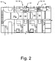
- FIG. 2 shows a schematic diagram of a portion of the steam turbine turbine 10 including a number of stages 52 positioned in a steam or hot gas path 54 of the steam turbine 10.
- a first stage 56 may include a number of circumferentially-spaced first-stage guides 58 and a number of circumferentially-spaced first-stage blades 60.
- the first stage 56 also may include a first-stage shroud 62 extending circumferentially and surrounding the first-stage blades 60.
- the first-stage shroud 62 may include a number of shroud segments positioned adjacent one another in an annular arrangement.
- a second stage 64 may include a number of second-stage guides 66, a number of second-stage blades 68, and a second-stage shroud 70 surrounding the second-stage blades 68. Any number of stages and corresponding guides and runners may be included. Other embodiments may have different configurations.
- FIG. 3 depicts a turbine bucket 80 as may be used in one of the stages 52 of the turbine 10.
- the bucket 80 may be used in the second stage 64 or a later stage of the turbine 10.
- the turbine bucket 80 may include a blade 82, a dovetail or root 84, and a platform 86 disposed between the blade 82 and the root 84.
- a number of the blades or buckets 80 may be arranged in a circumferential array within the stage 52 of the turbine 10. In this manner, the blade 82 of each bucket 80 may extend radially with respect to a central axis of the turbine 10, while the platform 86 of each bucket 80 extends circumferentially with respect to the central axis of the turbine 10.
- the blade 82 may extend radially outward from the root 84 to an optional tip shroud 88 positioned about a tip end 90 of the bucket 80.
- the tip shroud 88 may be integrally formed with the blade 82.
- the root 84 may extend radially inward from the platform 86 to a root end 92 of the bucket 80, such that the platform 86 generally defines an interface between the blade 82 and the root 84.
- the platform 86 may be formed so as to extend generally parallel to the central axis of the turbine 10 during operation thereof.
- the root 84 may be formed to define a root structure, such as a dovetail, configured to secure the bucket 80 to a turbine disc or drum of the turbine 10.
- the flow of steam or combustion gases 35 travels along the steam or hot gas path 54 and over the platform 86, which along with an outer circumference of the turbine disc forms the radially inner boundary of the steam or hot gas path 54. Accordingly, the flow of steam or combustion gases 35 is directed against the blade 82 of the bucket 80, and thus the surfaces of the blade 82 are subjected to very high temperatures.
- the steam turbine 100 may include a first controlled flow guide 120 for a first stage, and a first controlled flow runner 130 for the first stage.
- the first controlled flow runner 130 may be positioned adjacent to the first controlled flow guide 120.
- the first controlled flow guide 120 and the first controlled flow runner 130 may be coupled to a disc or drum 110.
- the guides of the steam turbine may be controlled flow guides and the runners may be controlled flow runners.
- the steam turbine 100 may include a second controlled flow guide 140 for a second stage, and a second controlled flow runner 150 for the second stage.
- the second controlled flow guide 140 may be a controlled flow guide and the second controlled flow runner 150 may be a controlled flow runner. Any number of stages and/or controlled flow guides and controlled flow runners may be included.
- One or more of the controlled flow runners may include a tip, a blade, and a root.
- the root may be configured to couple the runner to the disc 110.
- the blade may be positioned between the root and the tip.
- a tip shroud may be coupled to the tip.
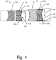
- the blade of the first controlled flow runner 130 may have a bowed configuration 132. Specifically, the blade of the first controlled flow runner 130 may have a reduced axial width about a midsection of the first controlled flow runner 130. As illustrated in FIG. 4 , the blade of the first controlled flow runner 130 may include a top width 134, a middle width 136, and a bottom width 138. The widths may be axial widths. The top width 134 may be an axial width of a top portion of the first controlled flow runner 130. The top width 134 may be a width of a portion of the first controlled flow runner 130, or more specifically, the blade, that is radially outward from the disc 110.
- the middle width 136 may be an axial width of the first controlled flow runner 130 or the blade that is determined or measured about a middle portion of the blade of the first controlled flow runner 130.
- the bottom width 138 may be an axial width of the blade or the first controlled flow runner 130 at a bottom portion, which may be adjacent to the disc or drum 110.
- the second controlled flow runner 150 may also have an axial width that varies at different distances measured from the root of the second controlled flow runner 150 or the turbine disc.
- the second controlled flow runner 150 may have a top axial width 152, a middle axial width 154, and a bottom axial width 156.
- the bottom axial width 156 may be an axial width of the second controlled flow runner 150 that is measured a first radial distance 158 from the disc 110.
- the middle axial width 154 may be an axial width of the second controlled flow runner 150 that is measured a second radial distance 160 from the disc 110.
- the second radial distance 160 may be greater than the first radial distance 158.
- the top axial width 152 may be an axial width of the second controlled flow runner 150 that is measured a third radial distance 162 from the disc 110.
- the third radial distance 162 may be greater than the first radial distance 158 and the second radial distance 160.
- the middle axial width 154 of the second controlled flow runner 150 may be reduced relative to the top axial width 152 and the bottom axial width 156, so as to result in reduced profile losses.
- the second controlled flow runner 150 may have a height that is greater than a height of the first controlled flow runner 130.
- the middle width of one or more, or all, of the runners in the steam turbine 100 may be less than the respective top widths and the bottom widths.
- the runners may therefore have a bowed configuration.
- the middle widths of the runners in the steam turbine 100 may be dimensioned so as to reduce profile losses. For example, dimensioning the middle width to be less than the top and/or bottom widths may reduce profile losses in the steam turbine 100.
- the bottom width of the respective runners may be greater than the top widths.
- the controlled flow runners may therefore be configured to accelerate guide wake and reduce mixing losses in the steam turbine 100.
- steam turbines may include multiple stages with respective pairs of controlled flow guides and controlled flow runners that correspond to respective turbine stages.
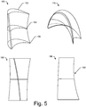
- a blade portion 164 of a controlled flow runner as described herein is depicted in perspective view.
- the blade portion 164 may have an airfoil geometry 162, with a bowed configuration 160 at a trailing edge.
- a bottom portion 166 of the blade portion 164 may have a different center of gravity than top or middle portions of the blade portion 164.
- the controlled flow runner may have a bowed stack configuration 160, where the tip, blade, and root are stacked with offset centers-of-gravity. Specifically, a first center of gravity of the tip of the runner may be offset from a second center of gravity of the blade. The second center of gravity of the blade may be offset from a third center of gravity of the root.
- the bowed trailing edge and/or the opening/pitch distribution of the blade may generate optimized controlled flow vortex distribution as gas passes over the controlled flow runner.
- FIG. 5 further illustrates the blade in a top perspective view 170, a front view 180, and a side view 190, which illustrates the bowed midsection 192 of the blade.
- FIG. 6 schematically depicts one example embodiment of a portion of a turbine 200.
- the turbine 200 may include a number of blades 202 positioned adjacent to one another to form a stage.
- the blades 202 may form the last stage of the turbine 200.
- Any number of blades 202 may be used herein to form any stage of the turbine 200.
- the blades 202 may form a first stage, a last stage, or any stage there between.
- the blades 202 may be attached to a disc and circumferentially spaced apart from one another.
- Each of the blades 202 may include a leading edge 208, a trailing edge 210, a pressure side 212, and a suction side 214.
- a passage 216 may be formed between adjacent blades 202.
- the passage 216 may include a throat area 218.
- the throat area 218 is the shortest distance from the trailing edge 210 to the suction side 214 of adjacent blades 202.
- the blades may have an ultra-high back surface deflection. In some embodiments, the back surface deflection may be greater than a threshold value, such as about 10 degrees, or between about 5 degrees and about 25 degrees.
- FIG. 6 further schematically illustrates mean section differences between a controlled flow runner as described herein, and another runner (shown in dashed lines).
- the differences in geometry are indicated by the change in position of the respective suction sides 220, 222 and pressure sides 228, 230, as well as the separation 226 between the leading edges and separation 224 between the trailing edges.
- FIG. 6 Tip section differences between a controlled flow runner as described herein, and another runner (shown in dashed lines) are also illustrated in FIG. 6 . As shown, differences in positioning of the suction sides 240, 242, and 246, 248, as well as differences in separation (which may be minimal), may result in increased strength and reduced losses.
- FIG. 6 further illustrates an example back surface deflection, represented by ⁇ , which may indicate uncovered flow turning on the suction surface, and may be an angle between a tangent to the suction surface at the throat point and a tangent drawn at the suction surface trailing edge circle blend point.
- ⁇ back surface deflection
- a method of using the controlled flow runners described herein may include the steps of providing a root for a controlled flow runner in a steam turbine, coupling a blade for the controlled flow runner to the root, where the blade has a top width, a middle width, and a bottom width, and where the middle width is less than the top width and the bottom width.
- the method may include coupling a tip to the blade.
- stage efficiency gains for steam turbines may be about 0.20%, with reduced profile loss at the controlled flow runner, reduced secondary loss, and improved positive incidence.
- Certain embodiments may be used to retrofit existing steam turbines.
- Certain embodiments may provide reduced weight runners with consistent mechanical reliability, while maintaining costs. The controlled flow runner may therefore improve stage efficiency, while maintaining or improving mechanical reliability and without increasing cost or complexity of the steam turbine. emissions may be reduced.
Landscapes
- Engineering & Computer Science (AREA)
- Mechanical Engineering (AREA)
- General Engineering & Computer Science (AREA)
- Physics & Mathematics (AREA)
- Fluid Mechanics (AREA)
- Architecture (AREA)
- Turbine Rotor Nozzle Sealing (AREA)
- Hydraulic Turbines (AREA)
Abstract
Description
- The present application and the resultant patent relate generally to axial flow turbines of any type and more particularly relate to controlled flow runners for steam turbines.
- Generally described, steam turbines and the like may have a defined steam path that includes a steam inlet, a turbine section, and a steam outlet. Steam leakage, either out of the steam path, or into the steam path from an area of higher pressure to an area of lower pressure, may adversely affect the operating efficiency of the steam turbine. For example, steam path leakage in the steam turbine between a rotating shaft and a circumferentially surrounding turbine casing may lower the overall efficiency of the steam turbine
- Steam may generally flow through a number of turbine stages typically disposed in series through first-stage guides and blades (or nozzles and buckets) and subsequently through guides and blades of later stages of the turbine. In this manner, the guides may direct the steam toward the respective blades, causing the blades to rotate and drive a load, such as an electrical generator and the like. The steam may be contained by circumferential shrouds surrounding the blades, which also may aid in directing the steam or combustion gases along the path. In this manner, the turbine guides, blades, and shrouds may be subjected to high temperatures resulting from the steam, which may result in the formation of hot spots and high thermal stresses in these components. Because the efficiency of a steam turbine is dependent on its operating temperatures, there is an ongoing demand for components positioned along the steam or hot gas path to be capable of withstanding increasingly higher temperatures without failure or decrease in useful life.
- Certain turbine blades may be formed with an airfoil geometry. The blades may be attached to tips and roots, where the roots are used to couple a blade to a disc or drum. The turbine blade geometry and dimensions may result in certain profile losses, secondary losses, leakage losses, mixing losses, etc. that may adversely affect efficiency and/or performance of a steam turbine.
- This application and the resultant patent provide controlled flow runners for use with steam turbines. An example controlled flow runner may include a tip shroud, a blade adjacent to the tip shroud, the blade having a top width, a middle width, and a bottom width, where the middle width is less than the top width and the bottom width, and a root attachment below the blade.
- This application and the resultant patent further provide a method of using a controlled flow runner with a steam turbine. The method may include the steps of providing a root for a controlled flow runner, coupling a blade for a controlled flow runner to the root, where the blade may include a top width, a middle width, and a bottom width, wherein the middle width is less than the top width and the bottom width, and coupling a tip to the blade.
- This application and the resultant patent further provide a steam turbine with a controlled flow runner. The steam turbine may include a disc, a first controlled flow guide mounted in the inner casing, and a first controlled flow runner coupled to the disc adjacent to the first controlled flow guide. The first controlled flow runner may include a first blade. The first blade may have a top width at a first radial distance from the disc, a middle width at a second radial distance from the disc, and a bottom width at a third radial distance from the disc. The middle width may be less than the top width and the bottom width, and the second radial distance may be greater than the first radial distance and less than the third radial distance.
- These and other features and improvements of this application and the resultant patent will become apparent to one of ordinary skill in the art upon review of the following detailed description when taken in conjunction with the several drawings and the appended claims.
-
-
FIG. 1 is a schematic diagram of a steam turbine. -
FIG. 2 is a schematic diagram of a portion of a turbine as may be used in the steam turbine ofFIG. 1 , showing a number of turbine stages. -
FIG. 3 is a front plan view of a turbine blade as may be used in the turbine ofFIG. 2 . -
FIG. 4 is a cross-sectional side view of a portion of a steam turbine with controlled flow runners as described herein. -
FIG. 5 depicts various perspective and side views of a controlled flow runner as described herein. -
FIG. 6 schematically depicts an example view of a portion of a turbine and a back surface deflection angle, according to an embodiment of the disclosure. - Referring now to the drawings, in which like numerals refer to like elements throughout the several views,
FIG. 1 shows a schematic diagram of an example of asteam turbine 10. Generally described, thesteam turbine 10 may include ahigh pressure section 15 and anintermediate pressure section 20. Other pressures in other sections also may be used herein. An outer shell orcasing 25 may be divided axially into anupper half section 30 and alower half section 35. Acentral section 40 of thecasing 25 may include a highpressure steam inlet 45 and an intermediatepressure steam inlet 50. Within thecasing 25, thehigh pressure section 15 and theintermediate pressure section 20 may be arranged about a rotor ordisc 55. Thedisc 55 may be supported by a number ofbearings 60. Asteam seal unit 65 may be located inboard of each of thebearings 60. Anannular section divider 70 may extend radially inward from thecentral section 40 towards the disc. Thedivider 70 may include a number ofpacking casings 75. Other components and other configurations may be used. - During operation, the high
pressure steam inlet 45 receives high pressure steam from a steam source. The steam may be routed through thehigh pressure section 15 such that work is extracted from the steam by rotation of thedisc 55. The steam exits thehigh pressure section 15 and then may be returned to the steam source for reheating. The reheated steam then may be rerouted to the intermediatepressure section inlet 50. The steam may be returned to theintermediate pressure section 20 at a reduced pressure as compared to the steam entering thehigh pressure section 15 but at a temperature that is approximately equal to the temperature of the steam entering thehigh pressure section 15. Accordingly, an operating pressure within thehigh pressure section 15 may be higher than an operating pressure within theintermediary section 20 such that the steam within thehigh pressure section 15 tends to flow towards theintermediate section 20 through leakage paths that may develop between thehigh pressure 15 and theintermediate pressure section 20. One such leakage path may extend through thepacking casing 75 about thedisc shaft 55. Other leaks may develop across thesteam seal unit 65 and elsewhere. -
FIG. 2 shows a schematic diagram of a portion of thesteam turbine turbine 10 including a number of stages 52 positioned in a steam orhot gas path 54 of thesteam turbine 10. A first stage 56 may include a number of circumferentially-spaced first-stage guides 58 and a number of circumferentially-spaced first-stage blades 60. The first stage 56 also may include a first-stage shroud 62 extending circumferentially and surrounding the first-stage blades 60. The first-stage shroud 62 may include a number of shroud segments positioned adjacent one another in an annular arrangement. In a similar manner, a second stage 64 may include a number of second-stage guides 66, a number of second-stage blades 68, and a second-stage shroud 70 surrounding the second-stage blades 68. Any number of stages and corresponding guides and runners may be included. Other embodiments may have different configurations. -
FIG. 3 depicts aturbine bucket 80 as may be used in one of the stages 52 of theturbine 10. For example, thebucket 80 may be used in the second stage 64 or a later stage of theturbine 10. Generally described, theturbine bucket 80 may include ablade 82, a dovetail orroot 84, and aplatform 86 disposed between theblade 82 and theroot 84. As described above, a number of the blades orbuckets 80 may be arranged in a circumferential array within the stage 52 of theturbine 10. In this manner, theblade 82 of eachbucket 80 may extend radially with respect to a central axis of theturbine 10, while theplatform 86 of eachbucket 80 extends circumferentially with respect to the central axis of theturbine 10. - The
blade 82 may extend radially outward from theroot 84 to anoptional tip shroud 88 positioned about atip end 90 of thebucket 80. In some embodiments, thetip shroud 88 may be integrally formed with theblade 82. Theroot 84 may extend radially inward from theplatform 86 to aroot end 92 of thebucket 80, such that theplatform 86 generally defines an interface between theblade 82 and theroot 84. As is shown, theplatform 86 may be formed so as to extend generally parallel to the central axis of theturbine 10 during operation thereof. Theroot 84 may be formed to define a root structure, such as a dovetail, configured to secure thebucket 80 to a turbine disc or drum of theturbine 10. During operation of theturbine 10, the flow of steam orcombustion gases 35 travels along the steam orhot gas path 54 and over theplatform 86, which along with an outer circumference of the turbine disc forms the radially inner boundary of the steam orhot gas path 54. Accordingly, the flow of steam orcombustion gases 35 is directed against theblade 82 of thebucket 80, and thus the surfaces of theblade 82 are subjected to very high temperatures. - Referring to
FIGS. 4 and5 , asteam turbine 100 with guides and runners as described herein is depicted in one embodiment. Thesteam turbine 100 may include a first controlledflow guide 120 for a first stage, and a first controlledflow runner 130 for the first stage. The first controlledflow runner 130 may be positioned adjacent to the first controlledflow guide 120. The first controlledflow guide 120 and the first controlledflow runner 130 may be coupled to a disc ordrum 110. The guides of the steam turbine may be controlled flow guides and the runners may be controlled flow runners. Thesteam turbine 100 may include a second controlledflow guide 140 for a second stage, and a second controlledflow runner 150 for the second stage. The second controlledflow guide 140 may be a controlled flow guide and the second controlledflow runner 150 may be a controlled flow runner. Any number of stages and/or controlled flow guides and controlled flow runners may be included. - One or more of the controlled flow runners, specifically the first controlled
flow runner 130 and the second controlledflow runner 150, may include a tip, a blade, and a root. The root may be configured to couple the runner to thedisc 110. The blade may be positioned between the root and the tip. In some embodiments, a tip shroud may be coupled to the tip. - The blade of the first controlled
flow runner 130 may have a bowedconfiguration 132. Specifically, the blade of the first controlledflow runner 130 may have a reduced axial width about a midsection of the first controlledflow runner 130. As illustrated inFIG. 4 , the blade of the first controlledflow runner 130 may include atop width 134, amiddle width 136, and abottom width 138. The widths may be axial widths. Thetop width 134 may be an axial width of a top portion of the first controlledflow runner 130. Thetop width 134 may be a width of a portion of the first controlledflow runner 130, or more specifically, the blade, that is radially outward from thedisc 110. Themiddle width 136 may be an axial width of the first controlledflow runner 130 or the blade that is determined or measured about a middle portion of the blade of the first controlledflow runner 130. Thebottom width 138 may be an axial width of the blade or the first controlledflow runner 130 at a bottom portion, which may be adjacent to the disc ordrum 110. - The second controlled
flow runner 150 may also have an axial width that varies at different distances measured from the root of the second controlledflow runner 150 or the turbine disc. For example, the second controlledflow runner 150 may have a topaxial width 152, a middleaxial width 154, and a bottomaxial width 156. The bottomaxial width 156 may be an axial width of the second controlledflow runner 150 that is measured afirst radial distance 158 from thedisc 110. The middleaxial width 154 may be an axial width of the second controlledflow runner 150 that is measured asecond radial distance 160 from thedisc 110. Thesecond radial distance 160 may be greater than thefirst radial distance 158. The topaxial width 152 may be an axial width of the second controlledflow runner 150 that is measured a thirdradial distance 162 from thedisc 110. The thirdradial distance 162 may be greater than thefirst radial distance 158 and thesecond radial distance 160. The middleaxial width 154 of the second controlledflow runner 150 may be reduced relative to the topaxial width 152 and the bottomaxial width 156, so as to result in reduced profile losses. As shown inFIG. 4 , the second controlledflow runner 150 may have a height that is greater than a height of the first controlledflow runner 130. - In some embodiments, the middle width of one or more, or all, of the runners in the
steam turbine 100, such as the first controlledflow runner 130 and the second controlledflow runner 150 may be less than the respective top widths and the bottom widths. The runners may therefore have a bowed configuration. The middle widths of the runners in thesteam turbine 100 may be dimensioned so as to reduce profile losses. For example, dimensioning the middle width to be less than the top and/or bottom widths may reduce profile losses in thesteam turbine 100. In some embodiments, the bottom width of the respective runners may be greater than the top widths. The controlled flow runners may therefore be configured to accelerate guide wake and reduce mixing losses in thesteam turbine 100. In some embodiments, steam turbines may include multiple stages with respective pairs of controlled flow guides and controlled flow runners that correspond to respective turbine stages. - In
FIG. 5 , ablade portion 164 of a controlled flow runner as described herein is depicted in perspective view. Theblade portion 164 may have anairfoil geometry 162, with a bowedconfiguration 160 at a trailing edge. Abottom portion 166 of theblade portion 164 may have a different center of gravity than top or middle portions of theblade portion 164. - The controlled flow runner may have a bowed
stack configuration 160, where the tip, blade, and root are stacked with offset centers-of-gravity. Specifically, a first center of gravity of the tip of the runner may be offset from a second center of gravity of the blade. The second center of gravity of the blade may be offset from a third center of gravity of the root. The bowed trailing edge and/or the opening/pitch distribution of the blade may generate optimized controlled flow vortex distribution as gas passes over the controlled flow runner.FIG. 5 further illustrates the blade in atop perspective view 170, afront view 180, and aside view 190, which illustrates the bowedmidsection 192 of the blade. -
FIG. 6 schematically depicts one example embodiment of a portion of aturbine 200. Theturbine 200 may include a number ofblades 202 positioned adjacent to one another to form a stage. In some instances, theblades 202 may form the last stage of theturbine 200. Any number ofblades 202 may be used herein to form any stage of theturbine 200. For example, theblades 202 may form a first stage, a last stage, or any stage there between. Theblades 202 may be attached to a disc and circumferentially spaced apart from one another. Each of theblades 202 may include aleading edge 208, a trailingedge 210, apressure side 212, and asuction side 214. Apassage 216 may be formed betweenadjacent blades 202. Thepassage 216 may include athroat area 218. Thethroat area 218 is the shortest distance from the trailingedge 210 to thesuction side 214 ofadjacent blades 202. The blades may have an ultra-high back surface deflection. In some embodiments, the back surface deflection may be greater than a threshold value, such as about 10 degrees, or between about 5 degrees and about 25 degrees. -
FIG. 6 further schematically illustrates mean section differences between a controlled flow runner as described herein, and another runner (shown in dashed lines). The differences in geometry are indicated by the change in position of therespective suction sides pressure sides separation 226 between the leading edges andseparation 224 between the trailing edges. - Tip section differences between a controlled flow runner as described herein, and another runner (shown in dashed lines) are also illustrated in
FIG. 6 . As shown, differences in positioning of the suction sides 240, 242, and 246, 248, as well as differences in separation (which may be minimal), may result in increased strength and reduced losses.FIG. 6 further illustrates an example back surface deflection, represented by δ, which may indicate uncovered flow turning on the suction surface, and may be an angle between a tangent to the suction surface at the throat point and a tangent drawn at the suction surface trailing edge circle blend point. - A method of using the controlled flow runners described herein may include the steps of providing a root for a controlled flow runner in a steam turbine, coupling a blade for the controlled flow runner to the root, where the blade has a top width, a middle width, and a bottom width, and where the middle width is less than the top width and the bottom width. The method may include coupling a tip to the blade.
- As a result of the controlled flow runners described herein, stage efficiency gains for steam turbines may be about 0.20%, with reduced profile loss at the controlled flow runner, reduced secondary loss, and improved positive incidence. Certain embodiments may be used to retrofit existing steam turbines. Certain embodiments may provide reduced weight runners with consistent mechanical reliability, while maintaining costs. The controlled flow runner may therefore improve stage efficiency, while maintaining or improving mechanical reliability and without increasing cost or complexity of the steam turbine. emissions may be reduced.
- It should be apparent that the foregoing relates only to certain embodiments of this application and resultant patent. Numerous changes and modifications may be made herein by one of ordinary skill in the art without departing from the general spirit and scope of the invention as defined by the following claims and the equivalents thereof. For completeness, various aspects of the invention are set out in the following numbered clauses:
- 1. A controlled flow runner for use with a steam turbine comprising:
- a tip; a blade adjacent to the tip, the blade comprising a top width, a middle width, and a bottom width, wherein the middle width is less than the top width and the bottom width;
- and a root adjacent to the blade.
- 2. The controlled flow runner of clause 1, wherein the blade comprises a bowed stack configuration.
- 3. The controlled flow runner of clause 1, wherein a first center of gravity of the blade is offset from a second center of gravity of the root.
- 4. The controlled flow runner of clause 3, wherein the first center of gravity is offset from a third center of gravity of the tip.
- 5. The controlled flow runner of clause 1, wherein the trailing edge of the blade comprises a bowed configuration.
- 6. The controlled flow runner of clause 5, wherein the opening/pitch distribution of the blade generates the optimized controlled flow vortex distribution.
- 7. The controlled flow runner of clause 1, wherein the bottom width is greater than the top width.
- 8. The controlled flow runner of clause 1, wherein the Back Surface Deflection of the blade is greater than a threshold value.
- 9. The controlled flow runner of clause 1, further comprising a tip shroud coupled to the tip, and wherein the top width is adjacent to the tip shroud.
- 10. The controlled flow runner of clause 1, wherein the middle width is an axial width.
- 11. The controlled flow runner of clause 1, wherein the middle width is dimensioned to reduce profile losses.
- 12. The controlled flow runner of clause 1, wherein the root is coupled to a disc, and wherein the bottom width is adjacent to the root.
- 13. The controlled flow runner of clause 1, wherein the blade is positioned adjacent to a controlled flow guide.
- 14. The controlled flow runner of clause 1, wherein the controlled flow runner is configured to accelerate guide wake and reduce mixing losses.
- 15. A method comprising:
- providing a root for a controlled flow runner in an inner casing of a steam turbine;
- coupling a blade for the controlled flow runner to the root, wherein the blade comprises a top width, a middle width, and a bottom width, wherein the middle width is less than the top width and the bottom width; and
- coupling a tip to the blade.
- 16. A steam turbine comprising:
- a disc;
- a casing;
- a first controlled flow guide installed in the casing; and
- a first controlled flow runner coupled to the disc adjacent to the first controlled flow guide, the first controlled flow runner comprising a first blade;
- the first blade comprising a top width at a first radial distance from the disc, a middle width at a second radial distance from the disc, and a bottom width at a third radial distance from the disc;
- wherein the middle width is less than the top width and the bottom width; and
- wherein the second radial distance is greater than the third radial distance and less than the first radial distance.
- 17. The steam turbine of clause 16, further comprising:
- a second controlled flow guide coupled to the disc;
- a second controlled flow runner coupled to the disc adjacent to the second controlled flow guide, the second controlled flow runner comprising a second blade, wherein the second blade has a height that is greater than a height of the first blade.
- a second controlled flow guide coupled to the disc;
- 18. The steam turbine of clause 17, wherein a back surface deflection of the first blade is greater than a threshold value.
- 19. The steam turbine of clause 16, further comprising a plurality of controlled flow guides and a plurality of controlled flow runners.
- 20. The steam turbine of clause 16, wherein respective pairs of controlled flow guides and controlled flow runners correspond to respective turbine stages.
Claims (15)
- A controlled flow runner (130) for use with a steam turbine (010) comprising:a tip;a blade (82) adjacent to the tip, the blade comprising a top width, a middle width, and a bottom width, wherein the middle width is less than the top width and the bottom width; anda root (84) adjacent to the blade.
- The controlled flow runner of claim 1, wherein the blade comprises a bowed stack configuration (132).
- The controlled flow runner of claim 1 or claim 2, wherein a first center of gravity of the blade is offset from a second center of gravity of the root.
- The controlled flow runner of claim 3, wherein the first center of gravity is offset from a third center of gravity of the tip.
- The controlled flow runner of any preceding claim, wherein the trailing edge (210) of the blade comprises a bowed configuration.
- The controlled flow runner of claim 5, wherein the opening/pitch distribution of the blade generates the optimized controlled flow vortex distribution.
- The controlled flow runner of any preceding claim, wherein the bottom width is greater than the top width.
- The controlled flow runner of any preceding claim, wherein the back surface deflection of the blade is greater than a threshold value.
- The controlled flow runner of any preceding claim, further comprising a tip shroud (88) coupled to the tip, and wherein the top width is adjacent to the tip shroud.
- The controlled flow runner of any preceding claim, wherein the middle width is an axial width.
- The controlled flow runner of any preceding claim, wherein the middle width is dimensioned to reduce profile losses.
- The controlled flow runner of any preceding claim, wherein the root is coupled to a disc (110), and wherein the bottom width is adjacent to the root.
- The controlled flow runner of any preceding claim, wherein the blade is positioned adjacent to a controlled flow guide or wherein the controlled flow runner is configured to accelerate guide wake and reduce mixing losses.
- A method comprising:providing a root for a controlled flow runner in an inner casing of a steam turbine;coupling a blade for the controlled flow runner to the root, wherein the blade comprises a top width, a middle width, and a bottom width, wherein the middle width is less than the top width and the bottom width; andcoupling a tip to the blade.
- A steam turbine (10) comprising:a disc (110);a casing;a first controlled flow guide (120) installed in the casing; anda first controlled flow runner (130) coupled to the disc adjacent to the first controlled flow guide, the first controlled flow runner comprising a first blade;the first blade comprising a top width at a first radial distance from the disc, a middle width at a second radial distance from the disc, and a bottom width at a third radial distance from the disc;wherein the middle width is less than the top width and the bottom width; andwherein the second radial distance is greater than the third radial distance and less than the first radial distance.
Priority Applications (6)
| Application Number | Priority Date | Filing Date | Title |
|---|---|---|---|
| EP17154386.1A EP3358134B1 (en) | 2017-02-02 | 2017-02-02 | Steam turbine with rotor blade |
| KR1020197022833A KR102496125B1 (en) | 2017-02-02 | 2018-02-01 | Controlled Flow Runners for Turbines |
| US16/483,201 US20200232327A1 (en) | 2017-02-02 | 2018-02-01 | Controlled flow runners for turbines |
| PCT/US2018/016330 WO2018144658A1 (en) | 2017-02-02 | 2018-02-01 | Controlled flow runners for turbines |
| CN201880010720.2A CN110268136A (en) | 2017-02-02 | 2018-02-01 | Controlled flow runners for turbines |
| JP2019541265A JP7106552B2 (en) | 2017-02-02 | 2018-02-01 | A steam turbine with an airfoil (82) having a backside camber. |
Applications Claiming Priority (1)
| Application Number | Priority Date | Filing Date | Title |
|---|---|---|---|
| EP17154386.1A EP3358134B1 (en) | 2017-02-02 | 2017-02-02 | Steam turbine with rotor blade |
Publications (2)
| Publication Number | Publication Date |
|---|---|
| EP3358134A1 true EP3358134A1 (en) | 2018-08-08 |
| EP3358134B1 EP3358134B1 (en) | 2021-07-14 |
Family
ID=57995034
Family Applications (1)
| Application Number | Title | Priority Date | Filing Date |
|---|---|---|---|
| EP17154386.1A Active EP3358134B1 (en) | 2017-02-02 | 2017-02-02 | Steam turbine with rotor blade |
Country Status (6)
| Country | Link |
|---|---|
| US (1) | US20200232327A1 (en) |
| EP (1) | EP3358134B1 (en) |
| JP (1) | JP7106552B2 (en) |
| KR (1) | KR102496125B1 (en) |
| CN (1) | CN110268136A (en) |
| WO (1) | WO2018144658A1 (en) |
Cited By (2)
| Publication number | Priority date | Publication date | Assignee | Title |
|---|---|---|---|---|
| EP3628817A1 (en) * | 2018-09-27 | 2020-04-01 | General Electric Company | Blade structure for turbomachine |
| EP3828389A1 (en) * | 2019-11-26 | 2021-06-02 | General Electric Company | Turbomachine nozzle with an airfoil having a circular trailing edge |
Citations (2)
| Publication number | Priority date | Publication date | Assignee | Title |
|---|---|---|---|---|
| US20080206065A1 (en) * | 2007-01-26 | 2008-08-28 | Yutaka Yamashita | Turbine bucket |
| US20100284801A1 (en) * | 2005-10-11 | 2010-11-11 | Alstom Technology Ltd | Turbo machine blade |
Family Cites Families (15)
| Publication number | Priority date | Publication date | Assignee | Title |
|---|---|---|---|---|
| US2392673A (en) * | 1943-08-27 | 1946-01-08 | Gen Electric | Elastic fluid turbine |
| CN1039874A (en) * | 1988-07-28 | 1990-02-21 | 四川重庆永荣矿务局 | Hyperbola variable cross-section blade |
| US5277549A (en) * | 1992-03-16 | 1994-01-11 | Westinghouse Electric Corp. | Controlled reaction L-2R steam turbine blade |
| JP3912989B2 (en) * | 2001-01-25 | 2007-05-09 | 三菱重工業株式会社 | gas turbine |
| JP2003269109A (en) | 2002-03-18 | 2003-09-25 | Toshiba Corp | Steam turbine |
| US8602727B2 (en) | 2010-07-22 | 2013-12-10 | General Electric Company | Turbine nozzle segment having arcuate concave leading edge |
| US8366397B2 (en) * | 2010-08-31 | 2013-02-05 | General Electric Company | Airfoil shape for a compressor |
| US8517688B2 (en) * | 2010-09-21 | 2013-08-27 | General Electric Company | Rotor assembly for use in turbine engines and methods for assembling same |
| JP5603800B2 (en) * | 2011-02-22 | 2014-10-08 | 株式会社日立製作所 | Turbine stationary blade and steam turbine equipment using the same |
| FR2977908B1 (en) | 2011-07-13 | 2016-11-25 | Snecma | TURBINE DAWN |
| JP5985351B2 (en) * | 2012-10-25 | 2016-09-06 | 三菱日立パワーシステムズ株式会社 | Axial flow turbine |
| JP6012519B2 (en) * | 2013-03-21 | 2016-10-25 | 三菱重工業株式会社 | Turbine and rotating machine equipped with the same |
| EP3023585B1 (en) * | 2014-11-21 | 2017-05-31 | General Electric Technology GmbH | Turbine arrangement |
| EP3059394B1 (en) | 2015-02-18 | 2019-10-30 | Ansaldo Energia Switzerland AG | Turbine blade and set of turbine blades |
| US10808535B2 (en) | 2018-09-27 | 2020-10-20 | General Electric Company | Blade structure for turbomachine |
-
2017
- 2017-02-02 EP EP17154386.1A patent/EP3358134B1/en active Active
-
2018
- 2018-02-01 CN CN201880010720.2A patent/CN110268136A/en active Pending
- 2018-02-01 JP JP2019541265A patent/JP7106552B2/en active Active
- 2018-02-01 WO PCT/US2018/016330 patent/WO2018144658A1/en not_active Ceased
- 2018-02-01 KR KR1020197022833A patent/KR102496125B1/en active Active
- 2018-02-01 US US16/483,201 patent/US20200232327A1/en not_active Abandoned
Patent Citations (2)
| Publication number | Priority date | Publication date | Assignee | Title |
|---|---|---|---|---|
| US20100284801A1 (en) * | 2005-10-11 | 2010-11-11 | Alstom Technology Ltd | Turbo machine blade |
| US20080206065A1 (en) * | 2007-01-26 | 2008-08-28 | Yutaka Yamashita | Turbine bucket |
Cited By (4)
| Publication number | Priority date | Publication date | Assignee | Title |
|---|---|---|---|---|
| EP3628817A1 (en) * | 2018-09-27 | 2020-04-01 | General Electric Company | Blade structure for turbomachine |
| US10808535B2 (en) | 2018-09-27 | 2020-10-20 | General Electric Company | Blade structure for turbomachine |
| EP3828389A1 (en) * | 2019-11-26 | 2021-06-02 | General Electric Company | Turbomachine nozzle with an airfoil having a circular trailing edge |
| US11566530B2 (en) | 2019-11-26 | 2023-01-31 | General Electric Company | Turbomachine nozzle with an airfoil having a circular trailing edge |
Also Published As
| Publication number | Publication date |
|---|---|
| CN110268136A (en) | 2019-09-20 |
| WO2018144658A1 (en) | 2018-08-09 |
| KR102496125B1 (en) | 2023-02-03 |
| US20200232327A1 (en) | 2020-07-23 |
| JP7106552B2 (en) | 2022-07-26 |
| KR20190107052A (en) | 2019-09-18 |
| EP3358134B1 (en) | 2021-07-14 |
| JP2020506325A (en) | 2020-02-27 |
Similar Documents
| Publication | Publication Date | Title |
|---|---|---|
| EP2820279B1 (en) | Turbomachine blade | |
| EP2199543B1 (en) | Rotor blade for a gas turbine engine and method of designing an airfoil | |
| US10934849B2 (en) | Endwall contouring for a turbomachine | |
| CN110094346B (en) | Passage between rotor platform and shroud in turbine engine | |
| JP6461382B2 (en) | Turbine blade with shroud | |
| US9464530B2 (en) | Turbine bucket and method for balancing a tip shroud of a turbine bucket | |
| JP2010156338A (en) | Turbine blade root configuration | |
| EP3012409B1 (en) | Turbine assembly | |
| US20180179901A1 (en) | Turbine blade with contoured tip shroud | |
| US20200232327A1 (en) | Controlled flow runners for turbines | |
| US8322972B2 (en) | Steampath flow separation reduction system | |
| EP2597262B1 (en) | Bucket assembly for turbine system | |
| EP3735517B1 (en) | Controlled flow guides for turbines | |
| US11199095B2 (en) | Controlled flow turbine blades | |
| WO2016033465A1 (en) | Gas turbine blade tip shroud flow guiding features | |
| US8052393B2 (en) | Steam turbine rotating blade for a low pressure section of a steam turbine engine | |
| US20210062657A1 (en) | Control stage blades for turbines |
Legal Events
| Date | Code | Title | Description |
|---|---|---|---|
| PUAI | Public reference made under article 153(3) epc to a published international application that has entered the european phase |
Free format text: ORIGINAL CODE: 0009012 |
|
| STAA | Information on the status of an ep patent application or granted ep patent |
Free format text: STATUS: THE APPLICATION HAS BEEN PUBLISHED |
|
| AK | Designated contracting states |
Kind code of ref document: A1 Designated state(s): AL AT BE BG CH CY CZ DE DK EE ES FI FR GB GR HR HU IE IS IT LI LT LU LV MC MK MT NL NO PL PT RO RS SE SI SK SM TR |
|
| AX | Request for extension of the european patent |
Extension state: BA ME |
|
| STAA | Information on the status of an ep patent application or granted ep patent |
Free format text: STATUS: REQUEST FOR EXAMINATION WAS MADE |
|
| 17P | Request for examination filed |
Effective date: 20190208 |
|
| RBV | Designated contracting states (corrected) |
Designated state(s): AL AT BE BG CH CY CZ DE DK EE ES FI FR GB GR HR HU IE IS IT LI LT LU LV MC MK MT NL NO PL PT RO RS SE SI SK SM TR |
|
| STAA | Information on the status of an ep patent application or granted ep patent |
Free format text: STATUS: EXAMINATION IS IN PROGRESS |
|
| 17Q | First examination report despatched |
Effective date: 20190806 |
|
| RIC1 | Information provided on ipc code assigned before grant |
Ipc: F01D 5/22 20060101ALN20201222BHEP Ipc: F01D 5/14 20060101AFI20201222BHEP |
|
| RIC1 | Information provided on ipc code assigned before grant |
Ipc: F01D 5/14 20060101AFI20210112BHEP Ipc: F01D 5/22 20060101ALN20210112BHEP |
|
| GRAP | Despatch of communication of intention to grant a patent |
Free format text: ORIGINAL CODE: EPIDOSNIGR1 |
|
| STAA | Information on the status of an ep patent application or granted ep patent |
Free format text: STATUS: GRANT OF PATENT IS INTENDED |
|
| RIC1 | Information provided on ipc code assigned before grant |
Ipc: F01D 5/14 20060101AFI20210122BHEP Ipc: F01D 5/22 20060101ALN20210122BHEP |
|
| INTG | Intention to grant announced |
Effective date: 20210223 |
|
| GRAS | Grant fee paid |
Free format text: ORIGINAL CODE: EPIDOSNIGR3 |
|
| GRAA | (expected) grant |
Free format text: ORIGINAL CODE: 0009210 |
|
| STAA | Information on the status of an ep patent application or granted ep patent |
Free format text: STATUS: THE PATENT HAS BEEN GRANTED |
|
| AK | Designated contracting states |
Kind code of ref document: B1 Designated state(s): AL AT BE BG CH CY CZ DE DK EE ES FI FR GB GR HR HU IE IS IT LI LT LU LV MC MK MT NL NO PL PT RO RS SE SI SK SM TR |
|
| REG | Reference to a national code |
Ref country code: GB Ref legal event code: FG4D |
|
| REG | Reference to a national code |
Ref country code: DE Ref legal event code: R096 Ref document number: 602017041973 Country of ref document: DE |
|
| REG | Reference to a national code |
Ref country code: IE Ref legal event code: FG4D |
|
| REG | Reference to a national code |
Ref country code: AT Ref legal event code: REF Ref document number: 1410807 Country of ref document: AT Kind code of ref document: T Effective date: 20210815 |
|
| REG | Reference to a national code |
Ref country code: SE Ref legal event code: TRGR |
|
| REG | Reference to a national code |
Ref country code: LT Ref legal event code: MG9D |
|
| REG | Reference to a national code |
Ref country code: NL Ref legal event code: MP Effective date: 20210714 |
|
| REG | Reference to a national code |
Ref country code: AT Ref legal event code: MK05 Ref document number: 1410807 Country of ref document: AT Kind code of ref document: T Effective date: 20210714 |
|
| PG25 | Lapsed in a contracting state [announced via postgrant information from national office to epo] |
Ref country code: RS Free format text: LAPSE BECAUSE OF FAILURE TO SUBMIT A TRANSLATION OF THE DESCRIPTION OR TO PAY THE FEE WITHIN THE PRESCRIBED TIME-LIMIT Effective date: 20210714 Ref country code: NL Free format text: LAPSE BECAUSE OF FAILURE TO SUBMIT A TRANSLATION OF THE DESCRIPTION OR TO PAY THE FEE WITHIN THE PRESCRIBED TIME-LIMIT Effective date: 20210714 Ref country code: NO Free format text: LAPSE BECAUSE OF FAILURE TO SUBMIT A TRANSLATION OF THE DESCRIPTION OR TO PAY THE FEE WITHIN THE PRESCRIBED TIME-LIMIT Effective date: 20211014 Ref country code: PT Free format text: LAPSE BECAUSE OF FAILURE TO SUBMIT A TRANSLATION OF THE DESCRIPTION OR TO PAY THE FEE WITHIN THE PRESCRIBED TIME-LIMIT Effective date: 20211115 Ref country code: HR Free format text: LAPSE BECAUSE OF FAILURE TO SUBMIT A TRANSLATION OF THE DESCRIPTION OR TO PAY THE FEE WITHIN THE PRESCRIBED TIME-LIMIT Effective date: 20210714 Ref country code: FI Free format text: LAPSE BECAUSE OF FAILURE TO SUBMIT A TRANSLATION OF THE DESCRIPTION OR TO PAY THE FEE WITHIN THE PRESCRIBED TIME-LIMIT Effective date: 20210714 Ref country code: ES Free format text: LAPSE BECAUSE OF FAILURE TO SUBMIT A TRANSLATION OF THE DESCRIPTION OR TO PAY THE FEE WITHIN THE PRESCRIBED TIME-LIMIT Effective date: 20210714 Ref country code: LT Free format text: LAPSE BECAUSE OF FAILURE TO SUBMIT A TRANSLATION OF THE DESCRIPTION OR TO PAY THE FEE WITHIN THE PRESCRIBED TIME-LIMIT Effective date: 20210714 Ref country code: BG Free format text: LAPSE BECAUSE OF FAILURE TO SUBMIT A TRANSLATION OF THE DESCRIPTION OR TO PAY THE FEE WITHIN THE PRESCRIBED TIME-LIMIT Effective date: 20211014 Ref country code: AT Free format text: LAPSE BECAUSE OF FAILURE TO SUBMIT A TRANSLATION OF THE DESCRIPTION OR TO PAY THE FEE WITHIN THE PRESCRIBED TIME-LIMIT Effective date: 20210714 |
|
| PG25 | Lapsed in a contracting state [announced via postgrant information from national office to epo] |
Ref country code: PL Free format text: LAPSE BECAUSE OF FAILURE TO SUBMIT A TRANSLATION OF THE DESCRIPTION OR TO PAY THE FEE WITHIN THE PRESCRIBED TIME-LIMIT Effective date: 20210714 Ref country code: LV Free format text: LAPSE BECAUSE OF FAILURE TO SUBMIT A TRANSLATION OF THE DESCRIPTION OR TO PAY THE FEE WITHIN THE PRESCRIBED TIME-LIMIT Effective date: 20210714 Ref country code: GR Free format text: LAPSE BECAUSE OF FAILURE TO SUBMIT A TRANSLATION OF THE DESCRIPTION OR TO PAY THE FEE WITHIN THE PRESCRIBED TIME-LIMIT Effective date: 20211015 |
|
| REG | Reference to a national code |
Ref country code: DE Ref legal event code: R097 Ref document number: 602017041973 Country of ref document: DE |
|
| PG25 | Lapsed in a contracting state [announced via postgrant information from national office to epo] |
Ref country code: DK Free format text: LAPSE BECAUSE OF FAILURE TO SUBMIT A TRANSLATION OF THE DESCRIPTION OR TO PAY THE FEE WITHIN THE PRESCRIBED TIME-LIMIT Effective date: 20210714 |
|
| PLBE | No opposition filed within time limit |
Free format text: ORIGINAL CODE: 0009261 |
|
| STAA | Information on the status of an ep patent application or granted ep patent |
Free format text: STATUS: NO OPPOSITION FILED WITHIN TIME LIMIT |
|
| PG25 | Lapsed in a contracting state [announced via postgrant information from national office to epo] |
Ref country code: SM Free format text: LAPSE BECAUSE OF FAILURE TO SUBMIT A TRANSLATION OF THE DESCRIPTION OR TO PAY THE FEE WITHIN THE PRESCRIBED TIME-LIMIT Effective date: 20210714 Ref country code: SK Free format text: LAPSE BECAUSE OF FAILURE TO SUBMIT A TRANSLATION OF THE DESCRIPTION OR TO PAY THE FEE WITHIN THE PRESCRIBED TIME-LIMIT Effective date: 20210714 Ref country code: RO Free format text: LAPSE BECAUSE OF FAILURE TO SUBMIT A TRANSLATION OF THE DESCRIPTION OR TO PAY THE FEE WITHIN THE PRESCRIBED TIME-LIMIT Effective date: 20210714 Ref country code: EE Free format text: LAPSE BECAUSE OF FAILURE TO SUBMIT A TRANSLATION OF THE DESCRIPTION OR TO PAY THE FEE WITHIN THE PRESCRIBED TIME-LIMIT Effective date: 20210714 Ref country code: AL Free format text: LAPSE BECAUSE OF FAILURE TO SUBMIT A TRANSLATION OF THE DESCRIPTION OR TO PAY THE FEE WITHIN THE PRESCRIBED TIME-LIMIT Effective date: 20210714 |
|
| 26N | No opposition filed |
Effective date: 20220419 |
|
| PG25 | Lapsed in a contracting state [announced via postgrant information from national office to epo] |
Ref country code: MC Free format text: LAPSE BECAUSE OF FAILURE TO SUBMIT A TRANSLATION OF THE DESCRIPTION OR TO PAY THE FEE WITHIN THE PRESCRIBED TIME-LIMIT Effective date: 20210714 |
|
| REG | Reference to a national code |
Ref country code: CH Ref legal event code: PL |
|
| REG | Reference to a national code |
Ref country code: BE Ref legal event code: MM Effective date: 20220228 |
|
| PG25 | Lapsed in a contracting state [announced via postgrant information from national office to epo] |
Ref country code: LU Free format text: LAPSE BECAUSE OF NON-PAYMENT OF DUE FEES Effective date: 20220202 |
|
| PG25 | Lapsed in a contracting state [announced via postgrant information from national office to epo] |
Ref country code: LI Free format text: LAPSE BECAUSE OF NON-PAYMENT OF DUE FEES Effective date: 20220228 Ref country code: IE Free format text: LAPSE BECAUSE OF NON-PAYMENT OF DUE FEES Effective date: 20220202 Ref country code: CH Free format text: LAPSE BECAUSE OF NON-PAYMENT OF DUE FEES Effective date: 20220228 |
|
| PG25 | Lapsed in a contracting state [announced via postgrant information from national office to epo] |
Ref country code: BE Free format text: LAPSE BECAUSE OF NON-PAYMENT OF DUE FEES Effective date: 20220228 |
|
| P01 | Opt-out of the competence of the unified patent court (upc) registered |
Effective date: 20230523 |
|
| REG | Reference to a national code |
Ref country code: DE Ref legal event code: R081 Ref document number: 602017041973 Country of ref document: DE Owner name: GENERAL ELECTRIC TECHNOLOGY GMBH, CH Free format text: FORMER OWNER: GENERAL ELECTRIC COMPANY, SCHENECTADY, NY, US |
|
| REG | Reference to a national code |
Ref country code: GB Ref legal event code: 732E Free format text: REGISTERED BETWEEN 20240222 AND 20240228 |
|
| PG25 | Lapsed in a contracting state [announced via postgrant information from national office to epo] |
Ref country code: HU Free format text: LAPSE BECAUSE OF FAILURE TO SUBMIT A TRANSLATION OF THE DESCRIPTION OR TO PAY THE FEE WITHIN THE PRESCRIBED TIME-LIMIT; INVALID AB INITIO Effective date: 20170202 |
|
| PG25 | Lapsed in a contracting state [announced via postgrant information from national office to epo] |
Ref country code: MK Free format text: LAPSE BECAUSE OF FAILURE TO SUBMIT A TRANSLATION OF THE DESCRIPTION OR TO PAY THE FEE WITHIN THE PRESCRIBED TIME-LIMIT Effective date: 20210714 Ref country code: CY Free format text: LAPSE BECAUSE OF FAILURE TO SUBMIT A TRANSLATION OF THE DESCRIPTION OR TO PAY THE FEE WITHIN THE PRESCRIBED TIME-LIMIT Effective date: 20210714 |
|
| PG25 | Lapsed in a contracting state [announced via postgrant information from national office to epo] |
Ref country code: MT Free format text: LAPSE BECAUSE OF FAILURE TO SUBMIT A TRANSLATION OF THE DESCRIPTION OR TO PAY THE FEE WITHIN THE PRESCRIBED TIME-LIMIT Effective date: 20210714 |
|
| PG25 | Lapsed in a contracting state [announced via postgrant information from national office to epo] |
Ref country code: TR Free format text: LAPSE BECAUSE OF FAILURE TO SUBMIT A TRANSLATION OF THE DESCRIPTION OR TO PAY THE FEE WITHIN THE PRESCRIBED TIME-LIMIT Effective date: 20210714 |
|
| PGFP | Annual fee paid to national office [announced via postgrant information from national office to epo] |
Ref country code: SE Payment date: 20260121 Year of fee payment: 10 |
|
| PGFP | Annual fee paid to national office [announced via postgrant information from national office to epo] |
Ref country code: GB Payment date: 20260122 Year of fee payment: 10 |
|
| PGFP | Annual fee paid to national office [announced via postgrant information from national office to epo] |
Ref country code: DE Payment date: 20260121 Year of fee payment: 10 |
|
| PGFP | Annual fee paid to national office [announced via postgrant information from national office to epo] |
Ref country code: IT Payment date: 20260121 Year of fee payment: 10 |
|
| PGFP | Annual fee paid to national office [announced via postgrant information from national office to epo] |
Ref country code: FR Payment date: 20260121 Year of fee payment: 10 |
|
| PGFP | Annual fee paid to national office [announced via postgrant information from national office to epo] |
Ref country code: CZ Payment date: 20260129 Year of fee payment: 10 |