EP3358024A1 - Cheek plate of reduced iron agglomeration apparatus - Google Patents
Cheek plate of reduced iron agglomeration apparatus Download PDFInfo
- Publication number
- EP3358024A1 EP3358024A1 EP16851970.0A EP16851970A EP3358024A1 EP 3358024 A1 EP3358024 A1 EP 3358024A1 EP 16851970 A EP16851970 A EP 16851970A EP 3358024 A1 EP3358024 A1 EP 3358024A1
- Authority
- EP
- European Patent Office
- Prior art keywords
- close contact
- cheek plate
- gas
- roller
- rollers
- Prior art date
- Legal status (The legal status is an assumption and is not a legal conclusion. Google has not performed a legal analysis and makes no representation as to the accuracy of the status listed.)
- Granted
Links
Images




Classifications
-
- C—CHEMISTRY; METALLURGY
- C22—METALLURGY; FERROUS OR NON-FERROUS ALLOYS; TREATMENT OF ALLOYS OR NON-FERROUS METALS
- C22B—PRODUCTION AND REFINING OF METALS; PRETREATMENT OF RAW MATERIALS
- C22B1/00—Preliminary treatment of ores or scrap
- C22B1/14—Agglomerating; Briquetting; Binding; Granulating
- C22B1/24—Binding; Briquetting ; Granulating
-
- B—PERFORMING OPERATIONS; TRANSPORTING
- B22—CASTING; POWDER METALLURGY
- B22F—WORKING METALLIC POWDER; MANUFACTURE OF ARTICLES FROM METALLIC POWDER; MAKING METALLIC POWDER; APPARATUS OR DEVICES SPECIALLY ADAPTED FOR METALLIC POWDER
- B22F3/00—Manufacture of workpieces or articles from metallic powder characterised by the manner of compacting or sintering; Apparatus specially adapted therefor ; Presses and furnaces
- B22F3/02—Compacting only
- B22F3/03—Press-moulding apparatus therefor
Definitions
- the present invention relates to cheek plates which are installed at both sides of rollers of an agglomeration apparatus and prevent a leakage of reduced iron.
- reduced fine iron ore Since reduced fine iron ore has high reactivity when the reduced fine iron ore is exposed to the air, there is a risk that the reduced fine iron ore is likely to be oxidized or ignited.
- the activity is caused by a specific surface area of the fine iron ore.
- the fine iron ore in the form of hematite is reduced to magnetite, such that a crystal structure thereof is greatly changed.
- the hematite and the magnetite are quite different from each other in terms of a lattice structure, and as a result, the change in crystal structure causes volume expansion and a lot of internal cracks.
- the occurrence of cracks increases a specific surface area of the ore and increases an area of the ore which may react with gas, thereby finally assisting in increasing a reduction rate.
- the reduced fine iron ore in the form of hematite and the reduced fine iron ore in the form of limonite have high reactivity because of a large specific surface area thereof, and as a result, the reduced fine iron ore in the form of hematite and the reduced fine iron ore in the form of limonite are highly likely to be ignited or reoxidized while reacting with oxygen even at room temperature.
- agglomeration technology there are a method of sintering fine iron ore by an oxidation reaction, and a method of plastically deforming reduced fine iron ore by physical pressure to make the fine iron ore in the form of a lump.
- the method of sintering the fine iron ore by the oxidation reaction is not economically advantageous because the method reoxidizes the reduced fine ore, and as a result, a method of compacting the fine iron ore by physical pressure is mainly used.
- the FINMET process, the FINEX process, and the like are performed by the process of agglomerating the reduced fine iron ore.
- the most efficient method of compacting the reduced fine iron ore is to supply and compress the reduced fine iron ore between two rotating rollers, and production may be adjusted by adjusting rotational speeds (rpm) of the rollers.
- This apparatus is called a roller compactor. While the reduced iron is compressed between the rotating rollers, the reduced iron leaks to both sides of the rollers because an axial length of the roller is limited. Plate-shaped objects are in close contact with both sides of the rollers in order to prevent the leakage of the reduced iron, and the plate-shaped object is called a cheek plate.
- the reduced iron is compressed and molded between the rotating rollers and between the cheek plates which are in close contact with the rotating rollers, and in this case, gas, which fills pores between particles in the reduced iron, is also compressed in a molded product.
- pressure which has been applied to the molded product, disappears, and the gas compressed in the molded product is expanded, which may cause the molded product to be destroyed.
- This situation is called a spring-back, and it is necessary to allow the gas to be discharged well from the cheek plates in order to prevent the spring-back, but it is difficult to discharge the gas because of the close contact between the rollers and the cheek plates.
- the present invention has been made in an effort to provide a cheek plate for an apparatus for agglomerating reduced iron, which is capable of effectively discharging gas, which is produced when processing the reduced iron, while increasing close contact force between the cheek plates and both sides of rollers.
- An exemplary embodiment of the present invention provides a cheek plate for an apparatus for agglomerating reduced iron, the cheek plate including: a cover portion which has a fan shape and is installed at each of both sides of a pair of rollers for processing the reduced iron to prevent the reduced iron from leaking to a lateral space formed between the rollers; roller close contact portions which protrude from inner rim portions of the cover portion and are in close contact with outer portions of the rollers to maintain airtightness of the space between the rollers; and gas discharge portions which extend along plate surfaces of the roller close contact portions, and discharge gas produced when processing the reduced iron.
- the roller close contact portions may be formed in a pair to be symmetrical to each other so that the roller close contact portions are in close contact with the rollers.
- the roller close contact portions may have a V shape protruding in a circumferential direction of the rollers.
- the gas discharge portion may include one or more gas guide grooves which guide the produced gas to the outside from the roller.
- the gas guide groove may extend along a surface of the roller close contact portion.
- the gas guide grooves may be formed to be symmetrical to each other along the surfaces of the roller close contact portions.
- the gas discharge portion may further include one or more gas discharge grooves which are formed in a horizontal direction with respect to a close contact surface of the roller close contact portion and discharge gas.
- the one or more gas discharge grooves may be formed at predetermined intervals in the horizontal direction with respect to the gas guide groove.
- the gas discharge groove and the gas guide groove may intersect each other.
- An internal cross-sectional shape of each of the gas discharge groove and the gas guide groove may be any one of triangular, quadrangular, and semi-circular shapes.
- the roller close contact portion may have a concave-convex portion in which a groove portion and a protruding portion are alternately formed by the gas guide groove.
- the protruding portion of the concave-convex portion may have a conical shape.
- the protruding portion which is in close contact with the roller, may have a double structure including a first contact portion and a second contact portion.
- the first contact portion of the protruding portion may be structured to initially come into contact with the roller.
- the second contact portion of the protruding portion may be structured to come into contact with the roller after the first contact portion is abraded because of the contact with the roller.
- the cheek plate may further include one or more drilled holes which are formed at positions adjacent to the gas guide grooves and guide discharge of gas.
- the gas, which is produced when processing reduced iron is effectively discharged, and as a result, it is possible to solve a problem of a limitation in supplying reduced iron powder, and it is also possible to prevent a loss of reduced iron powder.
- FIG. 1 is a view schematically illustrating a cheek plate for an apparatus for agglomerating reduced iron according to the exemplary embodiment of the present invention.
- FIG. 2 is a view schematically illustrating the cheek plate according to the exemplary embodiment of the present invention
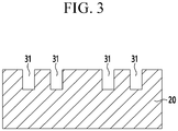
- FIG. 3 is a cross-sectional view taken along line A-A in FIG. 2 .
- a cheek plate 1 for an apparatus for agglomerating reduced iron is a structure that is in close contact with a lateral side of each of two rotating rollers 2 and blocks leakage of reduced iron.
- the cheek plate 1 broadly includes a cover portion 10, roller close contact portions 20, and gas discharge portions 30, and serves simultaneously to prevent the reduced iron from leaking to the outside and discharge gas produced from the reduced iron to the outside in a state in which the cheek plate 1 is in close contact with the roller 2.
- the cover portion 10 which defines a body of the cheek plate 1 and has a fan shape, is installed at each of both sides of the pair of rollers 2 for processing the reduced iron and prevents the reduced iron from leaking to a lateral space formed between the rollers 2, and the roller close contact portions 20 protrude from inner rim portions of the cover portion 10 and are in close contact with outer portions of the rollers 2 to maintain airtightness of the space between the rollers 2.
- the gas discharge portion 30 of the cheek plate 1 extends along a plate surface of the roller close contact portion 20 and discharges gas produced when processing the reduced iron.
- the roller close contact portions 20 are structured to be disposed in a pair to be symmetrical to each other so that the roller close contact portions 20 are in close contact with the rollers 2.
- the roller close contact portions 20 have a V-shaped structure protruding in a circumferential direction of the rollers 2, and the roller close contact portion 20 of the cheek plate 1 has an arc shape having a curvature so as to be effectively in close contact with the lateral side of the rotating roller 2.
- the gas discharge portion 30 has one or more gas guide grooves 31 that guide the produced gas to the outside from the roller 2.
- the gas guide groove 31 extends along a surface of the roller close contact portion 20.
- the gas guide grooves 31 may be structured to be symmetrical to each other along the surfaces of the roller close contact portions 20.
- the gas which is produced when compressing and molding reduced iron powder between the rollers 2, may be discharged through a portion where the roller 2 and the roller close contact portion 20 of the cheek plate 1 are in contact with each other.
- a contact portion between the roller 2 and the cheek plate 1 is not perfectly airtight, and as a result, a gap of several micrometers to several hundreds of nanometers is present in the contact portion, such that the gas may be discharged through the gap, but discharge resistance is increased as the contact portion is widened.
- the gas discharge portion 30 is configured by forming the multiple gas guide grooves 31 on the contact portion in order to reduce the discharge resistance, an area of the close contact portion is decreased, such that the discharge resistance may be decreased, and the gas may be discharged along the formed gas guide grooves 31, thereby assisting in discharging the gas produced when compressing the reduced iron powder.
- a depth of the gas guide groove 31 formed in the roller close contact portion 20 may be maintained within a range from 10 mm to 40 mm.
- the compressed gas is discharged through the gas discharge portion 30, and an overall contact area between the roller 2 and the roller close contact portion 20 is decreased because of the gas guide groove 31 formed as described above, but close contact pressure is increased, thereby improving a sealing effect of the reduced iron.
- FIG. 4 is a view schematically illustrating another structure of the cheek plate according to the exemplary embodiment of the present invention.
- FIG. 5 is a cross-sectional view taken along line A-A in FIG. 4 .
- FIG. 6 is a cross-sectional view taken along line B-B in FIG. 4 .
- the gas discharge portion 30 may further include one or more gas discharge grooves 32 which are formed in a horizontal direction with respect to the close contact surface of the roller close contact portion 20 and discharges gas.
- the one or more gas discharge grooves 32 are formed at predetermined intervals in the horizontal direction with respect to the gas guide groove 31, and the gas discharge groove 32 and the gas guide groove 31 intersect each other.
- An internal cross-sectional shape of each of the gas discharge groove 32 and the gas guide groove 31 may be any one of triangular, quadrangular, and semi-circular shapes.
- the gas discharge groove 32 may be further formed in addition to the gas discharge portion 30 in order to more effectively discharge gas from the cheek plate 1, and the gas discharge groove 32 and the gas guide groove 31 may be shaped in various shapes.
- FIG. 7 is a view schematically illustrating another structure of the gas discharge portion according to the exemplary embodiment of the present invention.
- the roller close contact portion 20 has concave-convex portions in which groove portions 21 and protruding portions 22 are alternately formed by the gas guide groove 31, and the protruding portion 22 of the concave-convex portion has a conical shape.
- Initial abrasion is promoted as the contact area between the roller 2 and the roller close contact portion 20 is decreased, such that the roller close contact portion 20 is in closer contact with the roller, and then an abrasion rate may be decreased by increasing the contact area.
- the protruding portion 22 which is in close contact with the roller 2, is formed to have a double structure including a first contact portion 22a and a second contact portion 22b.
- the first contact portion 22a of the protruding portion 22 is structured to initially come into contact with the roller 2
- the second contact portion 22b of the protruding portion 22 is structured to come into contact with the roller 2 after the first contact portion 22a is abraded because of the contact with the roller 2.
- the close contact surface of the roller close contact portion 20, which is in contact with the roller 2 has the multiple first contact portions 22a and the multiple second contact portions 22b, thereby decreasing an abrasion rate of the roller close contact portion 20.
- FIG. 8 is a view schematically illustrating another exemplary embodiment of the cheek plate according to the exemplary embodiment of the present invention.
- FIG. 9 is a cross-sectional view taken along line A-A in FIG. 8 .
- one or more drilled holes 33 capable of guiding the discharge of the gas may be further formed at positions adjacent to the gas guide grooves 31.
- the multiple drilled holes 33 are formed at predetermined intervals at the periphery of the gas guide grooves 31, thereby more effectively discharging the gas produced from the reduced iron.
- the gas produced when processing the reduced iron is effectively discharged, and as a result, it is possible to solve a problem of a limitation in supplying the reduced iron powder, prevent a loss of the reduced iron powder, and discharge the gas while increasing close contact force between the roller 2 and the cheek plate 1, thereby smoothly manufacturing briquettes (HCl) and improving quality of the produced briquettes.
- Cheek plate 2 Roller 10: Cover portion 20: Roller close contact portion 21: Groove portion 22: Protruding portion 22a: First contact portion 22b: Second contact portion 30: Gas discharge portion 31: Gas guide groove 32: Gas discharge groove 33: Drilled hole
Landscapes
- Engineering & Computer Science (AREA)
- Chemical & Material Sciences (AREA)
- Manufacturing & Machinery (AREA)
- Mechanical Engineering (AREA)
- Environmental & Geological Engineering (AREA)
- Organic Chemistry (AREA)
- Geochemistry & Mineralogy (AREA)
- Geology (AREA)
- Life Sciences & Earth Sciences (AREA)
- Materials Engineering (AREA)
- Metallurgy (AREA)
- General Life Sciences & Earth Sciences (AREA)
- Manufacture And Refinement Of Metals (AREA)
- Furnace Details (AREA)
- Manufacture Of Iron (AREA)
- Press Drives And Press Lines (AREA)
- Cleaning In General (AREA)
- Drying Of Solid Materials (AREA)
Abstract
Description
- The present invention relates to cheek plates which are installed at both sides of rollers of an agglomeration apparatus and prevent a leakage of reduced iron.
- Since reduced fine iron ore has high reactivity when the reduced fine iron ore is exposed to the air, there is a risk that the reduced fine iron ore is likely to be oxidized or ignited. The activity is caused by a specific surface area of the fine iron ore. The fine iron ore in the form of hematite is reduced to magnetite, such that a crystal structure thereof is greatly changed.
- The hematite and the magnetite are quite different from each other in terms of a lattice structure, and as a result, the change in crystal structure causes volume expansion and a lot of internal cracks. The occurrence of cracks increases a specific surface area of the ore and increases an area of the ore which may react with gas, thereby finally assisting in increasing a reduction rate.
- When a temperature of the fine iron ore in the form of limonite is raised to a temperature of 500°C or higher, crystal water present in the fine iron ore leaks to the outside such that the limonite is changed to the hematite. A space, which has been occupied by the crystal water, is exposed to the outside when the crystal water leaks, and as a result, an ore porosity and a specific surface area are increased. The reduced fine iron ore in the form of hematite and the reduced fine iron ore in the form of limonite have high reactivity because of a large specific surface area thereof, and as a result, the reduced fine iron ore in the form of hematite and the reduced fine iron ore in the form of limonite are highly likely to be ignited or reoxidized while reacting with oxygen even at room temperature.
- For this reason, there are great efforts to reduce reactivity of the fine iron ore by coating the fine iron ore or performing purge with nitrogen, but it is difficult to store the fine iron ore over a long period of time or basically prevent a likelihood of ignition when transporting the fine iron ore over a long distance.
- Therefore, it is necessary to reduce the specific surface area in order to reduce the reactivity of the fine iron ore, and thus a technology of agglomerating fine ore has been developed. As the agglomeration technology, there are a method of sintering fine iron ore by an oxidation reaction, and a method of plastically deforming reduced fine iron ore by physical pressure to make the fine iron ore in the form of a lump.
- The method of sintering the fine iron ore by the oxidation reaction is not economically advantageous because the method reoxidizes the reduced fine ore, and as a result, a method of compacting the fine iron ore by physical pressure is mainly used.
- The FINMET process, the FINEX process, and the like are performed by the process of agglomerating the reduced fine iron ore. The most efficient method of compacting the reduced fine iron ore is to supply and compress the reduced fine iron ore between two rotating rollers, and production may be adjusted by adjusting rotational speeds (rpm) of the rollers.
- This apparatus is called a roller compactor. While the reduced iron is compressed between the rotating rollers, the reduced iron leaks to both sides of the rollers because an axial length of the roller is limited. Plate-shaped objects are in close contact with both sides of the rollers in order to prevent the leakage of the reduced iron, and the plate-shaped object is called a cheek plate.
- Therefore, the reduced iron is compressed and molded between the rotating rollers and between the cheek plates which are in close contact with the rotating rollers, and in this case, gas, which fills pores between particles in the reduced iron, is also compressed in a molded product. When the molded product is unloaded from the rollers, pressure, which has been applied to the molded product, disappears, and the gas compressed in the molded product is expanded, which may cause the molded product to be destroyed.
- This situation is called a spring-back, and it is necessary to allow the gas to be discharged well from the cheek plates in order to prevent the spring-back, but it is difficult to discharge the gas because of the close contact between the rollers and the cheek plates.
- The present invention has been made in an effort to provide a cheek plate for an apparatus for agglomerating reduced iron, which is capable of effectively discharging gas, which is produced when processing the reduced iron, while increasing close contact force between the cheek plates and both sides of rollers.
- An exemplary embodiment of the present invention provides a cheek plate for an apparatus for agglomerating reduced iron, the cheek plate including: a cover portion which has a fan shape and is installed at each of both sides of a pair of rollers for processing the reduced iron to prevent the reduced iron from leaking to a lateral space formed between the rollers; roller close contact portions which protrude from inner rim portions of the cover portion and are in close contact with outer portions of the rollers to maintain airtightness of the space between the rollers; and gas discharge portions which extend along plate surfaces of the roller close contact portions, and discharge gas produced when processing the reduced iron.
- The roller close contact portions may be formed in a pair to be symmetrical to each other so that the roller close contact portions are in close contact with the rollers.
- The roller close contact portions may have a V shape protruding in a circumferential direction of the rollers. The gas discharge portion may include one or more gas guide grooves which guide the produced gas to the outside from the roller.
- The gas guide groove may extend along a surface of the roller close contact portion.
- The gas guide grooves may be formed to be symmetrical to each other along the surfaces of the roller close contact portions.
- The gas discharge portion may further include one or more gas discharge grooves which are formed in a horizontal direction with respect to a close contact surface of the roller close contact portion and discharge gas.
- The one or more gas discharge grooves may be formed at predetermined intervals in the horizontal direction with respect to the gas guide groove.
- The gas discharge groove and the gas guide groove may intersect each other.
- An internal cross-sectional shape of each of the gas discharge groove and the gas guide groove may be any one of triangular, quadrangular, and semi-circular shapes.
- The roller close contact portion may have a concave-convex portion in which a groove portion and a protruding portion are alternately formed by the gas guide groove.
- The protruding portion of the concave-convex portion may have a conical shape.
- The protruding portion, which is in close contact with the roller, may have a double structure including a first contact portion and a second contact portion.
- The first contact portion of the protruding portion may be structured to initially come into contact with the roller.
- The second contact portion of the protruding portion may be structured to come into contact with the roller after the first contact portion is abraded because of the contact with the roller.
- The cheek plate may further include one or more drilled holes which are formed at positions adjacent to the gas guide grooves and guide discharge of gas.
- According to an exemplary embodiment of the present invention, the gas, which is produced when processing reduced iron, is effectively discharged, and as a result, it is possible to solve a problem of a limitation in supplying reduced iron powder, and it is also possible to prevent a loss of reduced iron powder.
- In addition, it is possible to discharge gas while increasing close contact force between the rollers and the cheek plates, and as a result, it is possible to smoothly manufacture briquettes (HCI) and improve quality of the produced briquettes.
-
-
FIG. 1 is a view schematically illustrating a cheek plate for an apparatus for agglomerating reduced iron according to an exemplary embodiment of the present invention. -
FIG. 2 is a view schematically illustrating the cheek plate according to the exemplary embodiment of the present invention. -
FIG. 3 is a cross-sectional view taken along line A-A inFIG. 2 . -
FIG. 4 is a view schematically illustrating another structure of the cheek plate according to the exemplary embodiment of the present invention. -
FIG. 5 is a cross-sectional view taken along line A-A inFIG. 4 . -
FIG. 6 is a cross-sectional view taken along line B-B inFIG. 4 . -
FIG. 7 is a view schematically illustrating another structure of a gas discharge portion according to the exemplary embodiment of the present invention. -
FIG. 8 is a view schematically illustrating another exemplary embodiment of the cheek plate according to the exemplary embodiment of the present invention. -
FIG. 9 is a cross-sectional view taken along line A-A inFIG. 8 . - The technical terms used below are merely for the purpose of describing a specific exemplary embodiment, and not intended to limit the present invention. Singular expressions used herein include plural expressions unless they have definitely opposite meanings. The terms "comprises" and/or "comprising" used in the specification specify particular features, regions, integers, steps, operations, elements, components, but do not preclude the presence or addition of other particular features, regions integers, steps, operations, elements, components, and/or groups thereof.
- Hereinafter, exemplary embodiments of the present invention will be described in detail with reference to the accompanying drawings so that those skilled in the art to which the present invention pertains may easily carry out the exemplary embodiments. It can be easily understood by those skilled in the art to which the present invention pertains that the following exemplary embodiments may be modified to various forms without departing from the concept and the scope of the present invention. Therefore, the present invention can be implemented in various different forms, and is not limited to the exemplary embodiments described herein.
-
FIG. 1 is a view schematically illustrating a cheek plate for an apparatus for agglomerating reduced iron according to the exemplary embodiment of the present invention. -
FIG. 2 is a view schematically illustrating the cheek plate according to the exemplary embodiment of the present invention, andFIG. 3 is a cross-sectional view taken along line A-A inFIG. 2 . - As illustrated in
FIGS. 1 to 3 , acheek plate 1 for an apparatus for agglomerating reduced iron is a structure that is in close contact with a lateral side of each of two rotating rollers 2 and blocks leakage of reduced iron. - The
cheek plate 1 broadly includes acover portion 10, rollerclose contact portions 20, andgas discharge portions 30, and serves simultaneously to prevent the reduced iron from leaking to the outside and discharge gas produced from the reduced iron to the outside in a state in which thecheek plate 1 is in close contact with the roller 2. - That is, in the
cheek plate 1 for the apparatus for agglomerating reduced iron, thecover portion 10, which defines a body of thecheek plate 1 and has a fan shape, is installed at each of both sides of the pair of rollers 2 for processing the reduced iron and prevents the reduced iron from leaking to a lateral space formed between the rollers 2, and the rollerclose contact portions 20 protrude from inner rim portions of thecover portion 10 and are in close contact with outer portions of the rollers 2 to maintain airtightness of the space between the rollers 2. - In addition, the
gas discharge portion 30 of thecheek plate 1 extends along a plate surface of the rollerclose contact portion 20 and discharges gas produced when processing the reduced iron. - The roller
close contact portions 20 are structured to be disposed in a pair to be symmetrical to each other so that the rollerclose contact portions 20 are in close contact with the rollers 2. The rollerclose contact portions 20 have a V-shaped structure protruding in a circumferential direction of the rollers 2, and the rollerclose contact portion 20 of thecheek plate 1 has an arc shape having a curvature so as to be effectively in close contact with the lateral side of the rotating roller 2. - Further, the
gas discharge portion 30 has one or moregas guide grooves 31 that guide the produced gas to the outside from the roller 2. Thegas guide groove 31 extends along a surface of the rollerclose contact portion 20. Thegas guide grooves 31 may be structured to be symmetrical to each other along the surfaces of the rollerclose contact portions 20. - That is, the gas, which is produced when compressing and molding reduced iron powder between the rollers 2, may be discharged through a portion where the roller 2 and the roller
close contact portion 20 of thecheek plate 1 are in contact with each other. A contact portion between the roller 2 and thecheek plate 1 is not perfectly airtight, and as a result, a gap of several micrometers to several hundreds of nanometers is present in the contact portion, such that the gas may be discharged through the gap, but discharge resistance is increased as the contact portion is widened. - When the
gas discharge portion 30 is configured by forming the multiplegas guide grooves 31 on the contact portion in order to reduce the discharge resistance, an area of the close contact portion is decreased, such that the discharge resistance may be decreased, and the gas may be discharged along the formedgas guide grooves 31, thereby assisting in discharging the gas produced when compressing the reduced iron powder. - Therefore, it is possible to solve a problem of a limitation in supplying the reduced iron powder caused by the gas discharged from the
cheek plate 1 and also prevent a loss of the reduced iron powder. Therefore, it is possible to smoothly manufacture briquettes (HCI). - In addition, a depth of the
gas guide groove 31 formed in the rollerclose contact portion 20 may be maintained within a range from 10 mm to 40 mm. The compressed gas is discharged through thegas discharge portion 30, and an overall contact area between the roller 2 and the rollerclose contact portion 20 is decreased because of thegas guide groove 31 formed as described above, but close contact pressure is increased, thereby improving a sealing effect of the reduced iron. -
FIG. 4 is a view schematically illustrating another structure of the cheek plate according to the exemplary embodiment of the present invention. -
FIG. 5 is a cross-sectional view taken along line A-A inFIG. 4 . -
FIG. 6 is a cross-sectional view taken along line B-B inFIG. 4 . - As illustrated in
FIGS. 4 to 6 , thegas discharge portion 30 may further include one or moregas discharge grooves 32 which are formed in a horizontal direction with respect to the close contact surface of the rollerclose contact portion 20 and discharges gas. - In addition, the one or more
gas discharge grooves 32 are formed at predetermined intervals in the horizontal direction with respect to thegas guide groove 31, and thegas discharge groove 32 and thegas guide groove 31 intersect each other. An internal cross-sectional shape of each of thegas discharge groove 32 and thegas guide groove 31 may be any one of triangular, quadrangular, and semi-circular shapes. - That is, the
gas discharge groove 32 may be further formed in addition to thegas discharge portion 30 in order to more effectively discharge gas from thecheek plate 1, and thegas discharge groove 32 and thegas guide groove 31 may be shaped in various shapes. -
FIG. 7 is a view schematically illustrating another structure of the gas discharge portion according to the exemplary embodiment of the present invention. - As illustrated in
FIG. 7 , the rollerclose contact portion 20 has concave-convex portions in whichgroove portions 21 and protruding portions 22 are alternately formed by thegas guide groove 31, and the protruding portion 22 of the concave-convex portion has a conical shape. Initial abrasion is promoted as the contact area between the roller 2 and the rollerclose contact portion 20 is decreased, such that the rollerclose contact portion 20 is in closer contact with the roller, and then an abrasion rate may be decreased by increasing the contact area. - To this end, the protruding portion 22, which is in close contact with the roller 2, is formed to have a double structure including a first contact portion 22a and a
second contact portion 22b. The first contact portion 22a of the protruding portion 22 is structured to initially come into contact with the roller 2, and thesecond contact portion 22b of the protruding portion 22 is structured to come into contact with the roller 2 after the first contact portion 22a is abraded because of the contact with the roller 2. - That is, the close contact surface of the roller
close contact portion 20, which is in contact with the roller 2, has the multiple first contact portions 22a and the multiplesecond contact portions 22b, thereby decreasing an abrasion rate of the rollerclose contact portion 20. -
FIG. 8 is a view schematically illustrating another exemplary embodiment of the cheek plate according to the exemplary embodiment of the present invention. -
FIG. 9 is a cross-sectional view taken along line A-A inFIG. 8 . - As illustrated in
FIGS. 8 and9 , as another exemplary embodiment of thegas discharge portion 30, one or moredrilled holes 33 capable of guiding the discharge of the gas may be further formed at positions adjacent to thegas guide grooves 31. - The multiple drilled
holes 33 are formed at predetermined intervals at the periphery of thegas guide grooves 31, thereby more effectively discharging the gas produced from the reduced iron. - Therefore, the gas produced when processing the reduced iron is effectively discharged, and as a result, it is possible to solve a problem of a limitation in supplying the reduced iron powder, prevent a loss of the reduced iron powder, and discharge the gas while increasing close contact force between the roller 2 and the
cheek plate 1, thereby smoothly manufacturing briquettes (HCl) and improving quality of the produced briquettes. - While the exemplary embodiment of the present invention has been illustrated and described above, various modifications and other exemplary embodiments may be implemented by those skilled in the art. It is noted that all of the modifications and other exemplary embodiments are contemplated and included in the appended claims, and do not depart from the true purpose and the scope of the present invention.
<Description of symbols> 1: Cheek plate 2: Roller 10: Cover portion 20: Roller close contact portion 21: Groove portion 22: Protruding portion 22a: First contact portion 22b: Second contact portion 30: Gas discharge portion 31: Gas guide groove 32: Gas discharge groove 33: Drilled hole
Claims (16)
- A cheek plate for an apparatus for agglomerating reduced iron, the cheek plate comprising:a cover portion which has a fan shape and is installed at each of both sides of a pair of rollers for processing the reduced iron to prevent the reduced iron from leaking to a lateral space formed between the rollers;roller close contact portions which protrude from inner rim portions of the cover portion and are in close contact with outer portions of the rollers to maintain airtightness of the space between the rollers; andgas discharge portions which extend along plate surfaces of the roller close contact portions, and discharge gas produced when processing the reduced iron.
- The cheek plate of claim 1, wherein:
the roller close contact portions are formed in a pair to be symmetrical to each other so that the roller close contact portions are in close contact with the rollers. - The cheek plate of claim 1, wherein:
the roller close contact portions have a V shape protruding in a circumferential direction of the rollers. - The cheek plate of claim 1, wherein:
the gas discharge portion includes one or more gas guide grooves which guide the produced gas to the outside from the roller. - The cheek plate of claim 1 or 4, wherein:
the gas guide groove extends along a surface of the roller close contact portion. - The cheek plate of claim 5, wherein:
the gas guide grooves are formed to be symmetrical to each other along the surfaces of the roller close contact portions. - The cheek plate of claim 1, wherein:
the gas discharge portion further includes one or more gas discharge grooves which are formed in a horizontal direction with respect to a close contact surface of the roller close contact portion and discharge gas. - The cheek plate of claim 4 or 7, wherein:
the one or more gas discharge grooves are formed at predetermined intervals in the horizontal direction with respect to the gas guide groove. - The cheek plate of claim 8, wherein:
the gas discharge groove and the gas guide groove intersect each other. - The cheek plate of claim 8, wherein:
an internal cross-sectional shape of each of the gas discharge groove and the gas guide groove is any one of triangular, quadrangular, and semi-circular shapes. - The cheek plate of claim 1 or 4, wherein:
the roller close contact portion has a concave-convex portion in which a groove portion and a protruding portion are alternately formed by the gas guide groove. - The cheek plate of claim 11, wherein:
the protruding portion of the concave-convex portion has a conical shape. - The cheek plate of claim 11, wherein:
the protruding portion, which is in close contact with the roller, has a double structure including a first contact portion and a second contact portion. - The cheek plate of claim 13, wherein:
the first contact portion of the protruding portion is structured to initially come into contact with the roller. - The cheek plate of claim 13, wherein:
the second contact portion of the protruding portion is structured to come into contact with the roller after the first contact portion is abraded because of the contact with the roller. - The cheek plate of claim 4, further comprising:
one or more drilled holes which are formed at positions adjacent to the gas guide grooves and guide discharge of gas.
Applications Claiming Priority (2)
| Application Number | Priority Date | Filing Date | Title |
|---|---|---|---|
| KR1020150139327A KR101649546B1 (en) | 2015-10-02 | 2015-10-02 | Cheek plate of reduced iron roller compactor |
| PCT/KR2016/005995 WO2017057822A1 (en) | 2015-10-02 | 2016-06-07 | Cheek plate of reduced iron agglomeration apparatus |
Publications (3)
| Publication Number | Publication Date |
|---|---|
| EP3358024A1 true EP3358024A1 (en) | 2018-08-08 |
| EP3358024A4 EP3358024A4 (en) | 2018-10-10 |
| EP3358024B1 EP3358024B1 (en) | 2020-05-06 |
Family
ID=56875146
Family Applications (1)
| Application Number | Title | Priority Date | Filing Date |
|---|---|---|---|
| EP16851970.0A Active EP3358024B1 (en) | 2015-10-02 | 2016-06-07 | Apparatus for agglomerating reduced iron comprising a cheek plate |
Country Status (5)
| Country | Link |
|---|---|
| EP (1) | EP3358024B1 (en) |
| KR (1) | KR101649546B1 (en) |
| CN (1) | CN108138256B (en) |
| BR (1) | BR112018006594A2 (en) |
| WO (1) | WO2017057822A1 (en) |
Cited By (3)
| Publication number | Priority date | Publication date | Assignee | Title |
|---|---|---|---|---|
| DE102020104526A1 (en) | 2020-02-20 | 2021-08-26 | Maschinenfabrik Köppern Gmbh & Co. Kg | High pressure roller press |
| DE202021103408U1 (en) | 2021-06-25 | 2022-04-04 | Maschinenfabrik Köppern Gmbh & Co. Kg | high-pressure roller press |
| DE102021103573A1 (en) | 2021-02-16 | 2022-08-18 | Maschinenfabrik Köppern GmbH & Co KG | high-pressure roller press |
Family Cites Families (10)
| Publication number | Priority date | Publication date | Assignee | Title |
|---|---|---|---|---|
| DE3733500C2 (en) * | 1987-10-03 | 1993-11-04 | Alexanderwerk Ag | METHOD AND ROLLING PRESS FOR THE PRODUCTION OF PIECE OF MATERIAL FROM FINE-PIECE SMOKE GAS PLASTER |
| US5102058A (en) * | 1990-05-07 | 1992-04-07 | Ag Processing Inc., A Cooperative | Cheek plate for milling apparatus |
| JP3171367B2 (en) * | 1994-08-19 | 2001-05-28 | 新東工業株式会社 | Briquette machine |
| KR100825580B1 (en) * | 2002-05-02 | 2008-04-25 | 주식회사 포스코 | Easily Assembled Reduced Iron Manufacturing Equipment |
| KR101043078B1 (en) * | 2004-06-30 | 2011-06-21 | 주식회사 포스코 | Cheek plate pressurizing device and briquette manufacturing device using the same |
| WO2006004350A1 (en) * | 2004-06-30 | 2006-01-12 | Posco | Apparatus for manufacturing compacted irons of reduced materials comprising fine direct reduced irons and apparatus for manufacturing molten irons using the same |
| JP5844552B2 (en) * | 2011-06-01 | 2016-01-20 | 三井造船株式会社 | Method and apparatus for producing pellets or flakes |
| JP5851781B2 (en) * | 2011-09-26 | 2016-02-03 | 三井造船株式会社 | Gas hydrate compression molding equipment |
| KR101424609B1 (en) * | 2012-06-27 | 2014-07-31 | 주식회사 포스코 | Hot compacted iron machine |
| KR101527555B1 (en) * | 2013-10-25 | 2015-06-09 | 주식회사 포스코 | Hci compacting machine and cheek plate for the same |
-
2015
- 2015-10-02 KR KR1020150139327A patent/KR101649546B1/en active Active
-
2016
- 2016-06-07 EP EP16851970.0A patent/EP3358024B1/en active Active
- 2016-06-07 CN CN201680057529.4A patent/CN108138256B/en not_active Expired - Fee Related
- 2016-06-07 WO PCT/KR2016/005995 patent/WO2017057822A1/en not_active Ceased
- 2016-06-07 BR BR112018006594-3A patent/BR112018006594A2/en active Search and Examination
Cited By (9)
| Publication number | Priority date | Publication date | Assignee | Title |
|---|---|---|---|---|
| DE102020104526A1 (en) | 2020-02-20 | 2021-08-26 | Maschinenfabrik Köppern Gmbh & Co. Kg | High pressure roller press |
| WO2021164919A1 (en) | 2020-02-20 | 2021-08-26 | Maschinenfabrik Köppern Gmbh & Co. Kg | High-pressure roller press |
| DE102020104526B4 (en) | 2020-02-20 | 2024-03-28 | Maschinenfabrik Köppern Gmbh & Co. Kg | High pressure roller press |
| US12330167B2 (en) | 2020-02-20 | 2025-06-17 | Maschinenfabrik Koeppern Gmbh & Co. Kg | High-pressure roller press |
| DE102021103573A1 (en) | 2021-02-16 | 2022-08-18 | Maschinenfabrik Köppern GmbH & Co KG | high-pressure roller press |
| WO2022174957A1 (en) | 2021-02-16 | 2022-08-25 | Maschinenfabrik Köppern Gmbh & Co. Kg | High-pressure roller press |
| DE102021103573B4 (en) | 2021-02-16 | 2024-06-13 | Maschinenfabrik Köppern Gmbh & Co. Kg | High pressure roller press |
| US12508594B2 (en) | 2021-02-16 | 2025-12-30 | Maschinenfabrik Koeppern Gmbh & Co. Kg | High-pressure roller press |
| DE202021103408U1 (en) | 2021-06-25 | 2022-04-04 | Maschinenfabrik Köppern Gmbh & Co. Kg | high-pressure roller press |
Also Published As
| Publication number | Publication date |
|---|---|
| BR112018006594A2 (en) | 2018-10-23 |
| EP3358024A4 (en) | 2018-10-10 |
| EP3358024B1 (en) | 2020-05-06 |
| CN108138256B (en) | 2019-11-01 |
| WO2017057822A1 (en) | 2017-04-06 |
| KR101649546B1 (en) | 2016-08-19 |
| CN108138256A (en) | 2018-06-08 |
Similar Documents
| Publication | Publication Date | Title |
|---|---|---|
| EP3358024B1 (en) | Apparatus for agglomerating reduced iron comprising a cheek plate | |
| US9364883B2 (en) | Method of producing a separator | |
| CN102451871B (en) | Device capable of avoiding punching scrap bonding of stamping die | |
| EP3342586B1 (en) | Powder molding metal mold and method for manufacturing powder compacted molding | |
| US20120052194A1 (en) | Method of treating the surface of a cavity of a die used for casting | |
| CN104878187B (en) | One kind removes knurl method | |
| CA2416795A1 (en) | Winding tape and method of making winding tape | |
| CN114136096A (en) | A double labyrinth side sealing device for sintering machine | |
| CN109226375A (en) | Continuous bend manufacturing process in a kind of rolling surface of equal thickness circular arc class part | |
| CN204892581U (en) | Extrusion die | |
| JP4838019B2 (en) | Gas hydrate pellet manufacturing equipment | |
| US10451068B2 (en) | Tip seal | |
| WO2013090183A1 (en) | Single punch method of making battery plates for lead-acid batteries | |
| CN103047416B (en) | Be suitable for the seal ring assembly of pressurized container | |
| CN205173484U (en) | Compression roller main shaft gas seal structure of dry process granulator and have its roll -in mechanism | |
| JP2011011225A (en) | Method of sizing sintered part | |
| WO2015050183A1 (en) | Sliding component and manufacturing method therefor | |
| CN205718523U (en) | Double sand seal structures of the periodic kilns the kiln of high sealing performance | |
| CN203035550U (en) | Scroll compressor and scroll plate thereof | |
| JP4932137B2 (en) | Horizontal extrusion screw type extrusion granulator | |
| JP2005282706A (en) | Method for manufacture of roller | |
| CN217089554U (en) | Cigarette compounding machine guide rail and cigarette compounding machine | |
| JP4282084B2 (en) | Method for manufacturing sintered parts | |
| JP5796808B2 (en) | Mold for powder molding | |
| RU2530600C1 (en) | Two-radius testing roller |
Legal Events
| Date | Code | Title | Description |
|---|---|---|---|
| STAA | Information on the status of an ep patent application or granted ep patent |
Free format text: STATUS: THE INTERNATIONAL PUBLICATION HAS BEEN MADE |
|
| PUAI | Public reference made under article 153(3) epc to a published international application that has entered the european phase |
Free format text: ORIGINAL CODE: 0009012 |
|
| STAA | Information on the status of an ep patent application or granted ep patent |
Free format text: STATUS: REQUEST FOR EXAMINATION WAS MADE |
|
| 17P | Request for examination filed |
Effective date: 20180329 |
|
| AK | Designated contracting states |
Kind code of ref document: A1 Designated state(s): AL AT BE BG CH CY CZ DE DK EE ES FI FR GB GR HR HU IE IS IT LI LT LU LV MC MK MT NL NO PL PT RO RS SE SI SK SM TR |
|
| AX | Request for extension of the european patent |
Extension state: BA ME |
|
| A4 | Supplementary search report drawn up and despatched |
Effective date: 20180911 |
|
| RIC1 | Information provided on ipc code assigned before grant |
Ipc: C22B 1/24 20060101AFI20180905BHEP |
|
| DAV | Request for validation of the european patent (deleted) | ||
| DAX | Request for extension of the european patent (deleted) | ||
| STAA | Information on the status of an ep patent application or granted ep patent |
Free format text: STATUS: EXAMINATION IS IN PROGRESS |
|
| 17Q | First examination report despatched |
Effective date: 20190802 |
|
| GRAP | Despatch of communication of intention to grant a patent |
Free format text: ORIGINAL CODE: EPIDOSNIGR1 |
|
| STAA | Information on the status of an ep patent application or granted ep patent |
Free format text: STATUS: GRANT OF PATENT IS INTENDED |
|
| INTG | Intention to grant announced |
Effective date: 20191122 |
|
| GRAS | Grant fee paid |
Free format text: ORIGINAL CODE: EPIDOSNIGR3 |
|
| GRAA | (expected) grant |
Free format text: ORIGINAL CODE: 0009210 |
|
| STAA | Information on the status of an ep patent application or granted ep patent |
Free format text: STATUS: THE PATENT HAS BEEN GRANTED |
|
| AK | Designated contracting states |
Kind code of ref document: B1 Designated state(s): AL AT BE BG CH CY CZ DE DK EE ES FI FR GB GR HR HU IE IS IT LI LT LU LV MC MK MT NL NO PL PT RO RS SE SI SK SM TR |
|
| REG | Reference to a national code |
Ref country code: GB Ref legal event code: FG4D |
|
| REG | Reference to a national code |
Ref country code: CH Ref legal event code: EP Ref country code: AT Ref legal event code: REF Ref document number: 1266809 Country of ref document: AT Kind code of ref document: T Effective date: 20200515 |
|
| REG | Reference to a national code |
Ref country code: IE Ref legal event code: FG4D |
|
| REG | Reference to a national code |
Ref country code: DE Ref legal event code: R096 Ref document number: 602016036143 Country of ref document: DE |
|
| REG | Reference to a national code |
Ref country code: LT Ref legal event code: MG4D |
|
| REG | Reference to a national code |
Ref country code: NL Ref legal event code: MP Effective date: 20200506 |
|
| PG25 | Lapsed in a contracting state [announced via postgrant information from national office to epo] |
Ref country code: SE Free format text: LAPSE BECAUSE OF FAILURE TO SUBMIT A TRANSLATION OF THE DESCRIPTION OR TO PAY THE FEE WITHIN THE PRESCRIBED TIME-LIMIT Effective date: 20200506 Ref country code: PT Free format text: LAPSE BECAUSE OF FAILURE TO SUBMIT A TRANSLATION OF THE DESCRIPTION OR TO PAY THE FEE WITHIN THE PRESCRIBED TIME-LIMIT Effective date: 20200907 Ref country code: GR Free format text: LAPSE BECAUSE OF FAILURE TO SUBMIT A TRANSLATION OF THE DESCRIPTION OR TO PAY THE FEE WITHIN THE PRESCRIBED TIME-LIMIT Effective date: 20200807 Ref country code: FI Free format text: LAPSE BECAUSE OF FAILURE TO SUBMIT A TRANSLATION OF THE DESCRIPTION OR TO PAY THE FEE WITHIN THE PRESCRIBED TIME-LIMIT Effective date: 20200506 Ref country code: NO Free format text: LAPSE BECAUSE OF FAILURE TO SUBMIT A TRANSLATION OF THE DESCRIPTION OR TO PAY THE FEE WITHIN THE PRESCRIBED TIME-LIMIT Effective date: 20200806 Ref country code: IS Free format text: LAPSE BECAUSE OF FAILURE TO SUBMIT A TRANSLATION OF THE DESCRIPTION OR TO PAY THE FEE WITHIN THE PRESCRIBED TIME-LIMIT Effective date: 20200906 Ref country code: LT Free format text: LAPSE BECAUSE OF FAILURE TO SUBMIT A TRANSLATION OF THE DESCRIPTION OR TO PAY THE FEE WITHIN THE PRESCRIBED TIME-LIMIT Effective date: 20200506 |
|
| PG25 | Lapsed in a contracting state [announced via postgrant information from national office to epo] |
Ref country code: LV Free format text: LAPSE BECAUSE OF FAILURE TO SUBMIT A TRANSLATION OF THE DESCRIPTION OR TO PAY THE FEE WITHIN THE PRESCRIBED TIME-LIMIT Effective date: 20200506 Ref country code: RS Free format text: LAPSE BECAUSE OF FAILURE TO SUBMIT A TRANSLATION OF THE DESCRIPTION OR TO PAY THE FEE WITHIN THE PRESCRIBED TIME-LIMIT Effective date: 20200506 Ref country code: BG Free format text: LAPSE BECAUSE OF FAILURE TO SUBMIT A TRANSLATION OF THE DESCRIPTION OR TO PAY THE FEE WITHIN THE PRESCRIBED TIME-LIMIT Effective date: 20200806 Ref country code: HR Free format text: LAPSE BECAUSE OF FAILURE TO SUBMIT A TRANSLATION OF THE DESCRIPTION OR TO PAY THE FEE WITHIN THE PRESCRIBED TIME-LIMIT Effective date: 20200506 |
|
| PG25 | Lapsed in a contracting state [announced via postgrant information from national office to epo] |
Ref country code: NL Free format text: LAPSE BECAUSE OF FAILURE TO SUBMIT A TRANSLATION OF THE DESCRIPTION OR TO PAY THE FEE WITHIN THE PRESCRIBED TIME-LIMIT Effective date: 20200506 Ref country code: AL Free format text: LAPSE BECAUSE OF FAILURE TO SUBMIT A TRANSLATION OF THE DESCRIPTION OR TO PAY THE FEE WITHIN THE PRESCRIBED TIME-LIMIT Effective date: 20200506 |
|
| PG25 | Lapsed in a contracting state [announced via postgrant information from national office to epo] |
Ref country code: RO Free format text: LAPSE BECAUSE OF FAILURE TO SUBMIT A TRANSLATION OF THE DESCRIPTION OR TO PAY THE FEE WITHIN THE PRESCRIBED TIME-LIMIT Effective date: 20200506 Ref country code: CZ Free format text: LAPSE BECAUSE OF FAILURE TO SUBMIT A TRANSLATION OF THE DESCRIPTION OR TO PAY THE FEE WITHIN THE PRESCRIBED TIME-LIMIT Effective date: 20200506 Ref country code: EE Free format text: LAPSE BECAUSE OF FAILURE TO SUBMIT A TRANSLATION OF THE DESCRIPTION OR TO PAY THE FEE WITHIN THE PRESCRIBED TIME-LIMIT Effective date: 20200506 Ref country code: DK Free format text: LAPSE BECAUSE OF FAILURE TO SUBMIT A TRANSLATION OF THE DESCRIPTION OR TO PAY THE FEE WITHIN THE PRESCRIBED TIME-LIMIT Effective date: 20200506 Ref country code: IT Free format text: LAPSE BECAUSE OF FAILURE TO SUBMIT A TRANSLATION OF THE DESCRIPTION OR TO PAY THE FEE WITHIN THE PRESCRIBED TIME-LIMIT Effective date: 20200506 Ref country code: SM Free format text: LAPSE BECAUSE OF FAILURE TO SUBMIT A TRANSLATION OF THE DESCRIPTION OR TO PAY THE FEE WITHIN THE PRESCRIBED TIME-LIMIT Effective date: 20200506 Ref country code: ES Free format text: LAPSE BECAUSE OF FAILURE TO SUBMIT A TRANSLATION OF THE DESCRIPTION OR TO PAY THE FEE WITHIN THE PRESCRIBED TIME-LIMIT Effective date: 20200506 |
|
| REG | Reference to a national code |
Ref country code: CH Ref legal event code: PL |
|
| REG | Reference to a national code |
Ref country code: DE Ref legal event code: R097 Ref document number: 602016036143 Country of ref document: DE |
|
| PG25 | Lapsed in a contracting state [announced via postgrant information from national office to epo] |
Ref country code: PL Free format text: LAPSE BECAUSE OF FAILURE TO SUBMIT A TRANSLATION OF THE DESCRIPTION OR TO PAY THE FEE WITHIN THE PRESCRIBED TIME-LIMIT Effective date: 20200506 Ref country code: SK Free format text: LAPSE BECAUSE OF FAILURE TO SUBMIT A TRANSLATION OF THE DESCRIPTION OR TO PAY THE FEE WITHIN THE PRESCRIBED TIME-LIMIT Effective date: 20200506 Ref country code: MC Free format text: LAPSE BECAUSE OF FAILURE TO SUBMIT A TRANSLATION OF THE DESCRIPTION OR TO PAY THE FEE WITHIN THE PRESCRIBED TIME-LIMIT Effective date: 20200506 |
|
| PLBE | No opposition filed within time limit |
Free format text: ORIGINAL CODE: 0009261 |
|
| STAA | Information on the status of an ep patent application or granted ep patent |
Free format text: STATUS: NO OPPOSITION FILED WITHIN TIME LIMIT |
|
| PG25 | Lapsed in a contracting state [announced via postgrant information from national office to epo] |
Ref country code: LU Free format text: LAPSE BECAUSE OF NON-PAYMENT OF DUE FEES Effective date: 20200607 |
|
| 26N | No opposition filed |
Effective date: 20210209 |
|
| REG | Reference to a national code |
Ref country code: BE Ref legal event code: MM Effective date: 20200630 |
|
| GBPC | Gb: european patent ceased through non-payment of renewal fee |
Effective date: 20200806 |
|
| PG25 | Lapsed in a contracting state [announced via postgrant information from national office to epo] |
Ref country code: CH Free format text: LAPSE BECAUSE OF NON-PAYMENT OF DUE FEES Effective date: 20200630 Ref country code: LI Free format text: LAPSE BECAUSE OF NON-PAYMENT OF DUE FEES Effective date: 20200630 Ref country code: FR Free format text: LAPSE BECAUSE OF NON-PAYMENT OF DUE FEES Effective date: 20200706 Ref country code: IE Free format text: LAPSE BECAUSE OF NON-PAYMENT OF DUE FEES Effective date: 20200607 |
|
| PG25 | Lapsed in a contracting state [announced via postgrant information from national office to epo] |
Ref country code: BE Free format text: LAPSE BECAUSE OF NON-PAYMENT OF DUE FEES Effective date: 20200630 Ref country code: SI Free format text: LAPSE BECAUSE OF FAILURE TO SUBMIT A TRANSLATION OF THE DESCRIPTION OR TO PAY THE FEE WITHIN THE PRESCRIBED TIME-LIMIT Effective date: 20200506 |
|
| PG25 | Lapsed in a contracting state [announced via postgrant information from national office to epo] |
Ref country code: GB Free format text: LAPSE BECAUSE OF NON-PAYMENT OF DUE FEES Effective date: 20200806 |
|
| PG25 | Lapsed in a contracting state [announced via postgrant information from national office to epo] |
Ref country code: TR Free format text: LAPSE BECAUSE OF FAILURE TO SUBMIT A TRANSLATION OF THE DESCRIPTION OR TO PAY THE FEE WITHIN THE PRESCRIBED TIME-LIMIT Effective date: 20200506 Ref country code: MT Free format text: LAPSE BECAUSE OF FAILURE TO SUBMIT A TRANSLATION OF THE DESCRIPTION OR TO PAY THE FEE WITHIN THE PRESCRIBED TIME-LIMIT Effective date: 20200506 Ref country code: CY Free format text: LAPSE BECAUSE OF FAILURE TO SUBMIT A TRANSLATION OF THE DESCRIPTION OR TO PAY THE FEE WITHIN THE PRESCRIBED TIME-LIMIT Effective date: 20200506 |
|
| PG25 | Lapsed in a contracting state [announced via postgrant information from national office to epo] |
Ref country code: MK Free format text: LAPSE BECAUSE OF FAILURE TO SUBMIT A TRANSLATION OF THE DESCRIPTION OR TO PAY THE FEE WITHIN THE PRESCRIBED TIME-LIMIT Effective date: 20200506 |
|
| REG | Reference to a national code |
Ref country code: AT Ref legal event code: MM01 Ref document number: 1266809 Country of ref document: AT Kind code of ref document: T Effective date: 20210607 |
|
| REG | Reference to a national code |
Ref country code: DE Ref legal event code: R081 Ref document number: 602016036143 Country of ref document: DE Owner name: POSCO CO., LTD, POHANG-SI, KR Free format text: FORMER OWNER: POSCO, POHANG-SI, GYEONGSANGBUK-DO, KR Ref country code: DE Ref legal event code: R081 Ref document number: 602016036143 Country of ref document: DE Owner name: POSCO CO., LTD, POHANG- SI, KR Free format text: FORMER OWNER: POSCO, POHANG-SI, GYEONGSANGBUK-DO, KR Ref country code: DE Ref legal event code: R081 Ref document number: 602016036143 Country of ref document: DE Owner name: POSCO HOLDINGS INC., KR Free format text: FORMER OWNER: POSCO, POHANG-SI, GYEONGSANGBUK-DO, KR |
|
| PG25 | Lapsed in a contracting state [announced via postgrant information from national office to epo] |
Ref country code: AT Free format text: LAPSE BECAUSE OF NON-PAYMENT OF DUE FEES Effective date: 20210607 |
|
| REG | Reference to a national code |
Ref country code: DE Ref legal event code: R081 Ref document number: 602016036143 Country of ref document: DE Owner name: POSCO CO., LTD, POHANG-SI, KR Free format text: FORMER OWNER: POSCO HOLDINGS INC., SEOUL, KR Ref country code: DE Ref legal event code: R081 Ref document number: 602016036143 Country of ref document: DE Owner name: POSCO CO., LTD, POHANG- SI, KR Free format text: FORMER OWNER: POSCO HOLDINGS INC., SEOUL, KR |
|
| PGFP | Annual fee paid to national office [announced via postgrant information from national office to epo] |
Ref country code: DE Payment date: 20250320 Year of fee payment: 10 |