EP3357829A1 - Container - Google Patents
Container Download PDFInfo
- Publication number
- EP3357829A1 EP3357829A1 EP18154492.5A EP18154492A EP3357829A1 EP 3357829 A1 EP3357829 A1 EP 3357829A1 EP 18154492 A EP18154492 A EP 18154492A EP 3357829 A1 EP3357829 A1 EP 3357829A1
- Authority
- EP
- European Patent Office
- Prior art keywords
- box
- flange
- flanges
- walls
- plastic container
- Prior art date
- Legal status (The legal status is an assumption and is not a legal conclusion. Google has not performed a legal analysis and makes no representation as to the accuracy of the status listed.)
- Withdrawn
Links
Images


Classifications
-
- A—HUMAN NECESSITIES
- A47—FURNITURE; DOMESTIC ARTICLES OR APPLIANCES; COFFEE MILLS; SPICE MILLS; SUCTION CLEANERS IN GENERAL
- A47B—TABLES; DESKS; OFFICE FURNITURE; CABINETS; DRAWERS; GENERAL DETAILS OF FURNITURE
- A47B67/00—Chests; Dressing-tables; Medicine cabinets or the like; Cabinets characterised by the arrangement of drawers
- A47B67/04—Chests of drawers; Cabinets characterised by the arrangement of drawers
-
- B—PERFORMING OPERATIONS; TRANSPORTING
- B65—CONVEYING; PACKING; STORING; HANDLING THIN OR FILAMENTARY MATERIAL
- B65D—CONTAINERS FOR STORAGE OR TRANSPORT OF ARTICLES OR MATERIALS, e.g. BAGS, BARRELS, BOTTLES, BOXES, CANS, CARTONS, CRATES, DRUMS, JARS, TANKS, HOPPERS, FORWARDING CONTAINERS; ACCESSORIES, CLOSURES, OR FITTINGS THEREFOR; PACKAGING ELEMENTS; PACKAGES
- B65D43/00—Lids or covers for rigid or semi-rigid containers
- B65D43/02—Removable lids or covers
- B65D43/0202—Removable lids or covers without integral tamper element
- B65D43/0204—Removable lids or covers without integral tamper element secured by snapping over beads or projections
- B65D43/0212—Removable lids or covers without integral tamper element secured by snapping over beads or projections only on the outside, or a part turned to the outside, of the mouth
-
- A—HUMAN NECESSITIES
- A47—FURNITURE; DOMESTIC ARTICLES OR APPLIANCES; COFFEE MILLS; SPICE MILLS; SUCTION CLEANERS IN GENERAL
- A47B—TABLES; DESKS; OFFICE FURNITURE; CABINETS; DRAWERS; GENERAL DETAILS OF FURNITURE
- A47B88/00—Drawers for tables, cabinets or like furniture; Guides for drawers
- A47B88/40—Sliding drawers; Slides or guides therefor
- A47B88/407—Adjustably or detachably mounted drawers
-
- A—HUMAN NECESSITIES
- A47—FURNITURE; DOMESTIC ARTICLES OR APPLIANCES; COFFEE MILLS; SPICE MILLS; SUCTION CLEANERS IN GENERAL
- A47B—TABLES; DESKS; OFFICE FURNITURE; CABINETS; DRAWERS; GENERAL DETAILS OF FURNITURE
- A47B88/00—Drawers for tables, cabinets or like furniture; Guides for drawers
- A47B88/40—Sliding drawers; Slides or guides therefor
- A47B88/483—Sliding drawers; Slides or guides therefor with single extensible guides or parts
-
- A—HUMAN NECESSITIES
- A47—FURNITURE; DOMESTIC ARTICLES OR APPLIANCES; COFFEE MILLS; SPICE MILLS; SUCTION CLEANERS IN GENERAL
- A47B—TABLES; DESKS; OFFICE FURNITURE; CABINETS; DRAWERS; GENERAL DETAILS OF FURNITURE
- A47B88/00—Drawers for tables, cabinets or like furniture; Guides for drawers
- A47B88/90—Constructional details of drawers
- A47B88/906—Drawers being made of one piece of material, e.g. formed from folded sheet material or moulded
-
- B—PERFORMING OPERATIONS; TRANSPORTING
- B65—CONVEYING; PACKING; STORING; HANDLING THIN OR FILAMENTARY MATERIAL
- B65D—CONTAINERS FOR STORAGE OR TRANSPORT OF ARTICLES OR MATERIALS, e.g. BAGS, BARRELS, BOTTLES, BOXES, CANS, CARTONS, CRATES, DRUMS, JARS, TANKS, HOPPERS, FORWARDING CONTAINERS; ACCESSORIES, CLOSURES, OR FITTINGS THEREFOR; PACKAGING ELEMENTS; PACKAGES
- B65D1/00—Rigid or semi-rigid containers having bodies formed in one piece, e.g. by casting metallic material, by moulding plastics, by blowing vitreous material, by throwing ceramic material, by moulding pulped fibrous material or by deep-drawing operations performed on sheet material
- B65D1/34—Trays or like shallow containers
-
- B—PERFORMING OPERATIONS; TRANSPORTING
- B65—CONVEYING; PACKING; STORING; HANDLING THIN OR FILAMENTARY MATERIAL
- B65D—CONTAINERS FOR STORAGE OR TRANSPORT OF ARTICLES OR MATERIALS, e.g. BAGS, BARRELS, BOTTLES, BOXES, CANS, CARTONS, CRATES, DRUMS, JARS, TANKS, HOPPERS, FORWARDING CONTAINERS; ACCESSORIES, CLOSURES, OR FITTINGS THEREFOR; PACKAGING ELEMENTS; PACKAGES
- B65D1/00—Rigid or semi-rigid containers having bodies formed in one piece, e.g. by casting metallic material, by moulding plastics, by blowing vitreous material, by throwing ceramic material, by moulding pulped fibrous material or by deep-drawing operations performed on sheet material
- B65D1/40—Details of walls
- B65D1/42—Reinforcing or strengthening parts or members
-
- B—PERFORMING OPERATIONS; TRANSPORTING
- B65—CONVEYING; PACKING; STORING; HANDLING THIN OR FILAMENTARY MATERIAL
- B65D—CONTAINERS FOR STORAGE OR TRANSPORT OF ARTICLES OR MATERIALS, e.g. BAGS, BARRELS, BOTTLES, BOXES, CANS, CARTONS, CRATES, DRUMS, JARS, TANKS, HOPPERS, FORWARDING CONTAINERS; ACCESSORIES, CLOSURES, OR FITTINGS THEREFOR; PACKAGING ELEMENTS; PACKAGES
- B65D43/00—Lids or covers for rigid or semi-rigid containers
- B65D43/02—Removable lids or covers
- B65D43/0202—Removable lids or covers without integral tamper element
- B65D43/0214—Removable lids or covers without integral tamper element secured only by friction or gravity
-
- A—HUMAN NECESSITIES
- A47—FURNITURE; DOMESTIC ARTICLES OR APPLIANCES; COFFEE MILLS; SPICE MILLS; SUCTION CLEANERS IN GENERAL
- A47B—TABLES; DESKS; OFFICE FURNITURE; CABINETS; DRAWERS; GENERAL DETAILS OF FURNITURE
- A47B2210/00—General construction of drawers, guides and guide devices
- A47B2210/0002—Guide construction for drawers
- A47B2210/0051—Guide position
- A47B2210/0062—Guide located at the top of the drawer
-
- A—HUMAN NECESSITIES
- A47—FURNITURE; DOMESTIC ARTICLES OR APPLIANCES; COFFEE MILLS; SPICE MILLS; SUCTION CLEANERS IN GENERAL
- A47B—TABLES; DESKS; OFFICE FURNITURE; CABINETS; DRAWERS; GENERAL DETAILS OF FURNITURE
- A47B2210/00—General construction of drawers, guides and guide devices
- A47B2210/08—Covers or lids for sliding drawers
-
- A—HUMAN NECESSITIES
- A47—FURNITURE; DOMESTIC ARTICLES OR APPLIANCES; COFFEE MILLS; SPICE MILLS; SUCTION CLEANERS IN GENERAL
- A47B—TABLES; DESKS; OFFICE FURNITURE; CABINETS; DRAWERS; GENERAL DETAILS OF FURNITURE
- A47B88/00—Drawers for tables, cabinets or like furniture; Guides for drawers
- A47B88/90—Constructional details of drawers
- A47B88/919—Accessories or additional elements for drawers, e.g. drawer lighting
-
- B—PERFORMING OPERATIONS; TRANSPORTING
- B65—CONVEYING; PACKING; STORING; HANDLING THIN OR FILAMENTARY MATERIAL
- B65D—CONTAINERS FOR STORAGE OR TRANSPORT OF ARTICLES OR MATERIALS, e.g. BAGS, BARRELS, BOTTLES, BOXES, CANS, CARTONS, CRATES, DRUMS, JARS, TANKS, HOPPERS, FORWARDING CONTAINERS; ACCESSORIES, CLOSURES, OR FITTINGS THEREFOR; PACKAGING ELEMENTS; PACKAGES
- B65D2543/00—Lids or covers essentially for box-like containers
- B65D2543/00009—Details of lids or covers for rigid or semi-rigid containers
- B65D2543/00018—Overall construction of the lid
- B65D2543/00064—Shape of the outer periphery
- B65D2543/0012—Shape of the outer periphery having straight sides, e.g. with curved corners
- B65D2543/00175—Shape of the outer periphery having straight sides, e.g. with curved corners four straight sides, e.g. trapezium or diamond
- B65D2543/00194—Shape of the outer periphery having straight sides, e.g. with curved corners four straight sides, e.g. trapezium or diamond square or rectangular
-
- B—PERFORMING OPERATIONS; TRANSPORTING
- B65—CONVEYING; PACKING; STORING; HANDLING THIN OR FILAMENTARY MATERIAL
- B65D—CONTAINERS FOR STORAGE OR TRANSPORT OF ARTICLES OR MATERIALS, e.g. BAGS, BARRELS, BOTTLES, BOXES, CANS, CARTONS, CRATES, DRUMS, JARS, TANKS, HOPPERS, FORWARDING CONTAINERS; ACCESSORIES, CLOSURES, OR FITTINGS THEREFOR; PACKAGING ELEMENTS; PACKAGES
- B65D2543/00—Lids or covers essentially for box-like containers
- B65D2543/00009—Details of lids or covers for rigid or semi-rigid containers
- B65D2543/00444—Contact between the container and the lid
- B65D2543/00574—Contact between the container and the lid secured locally, i.e. a lot less than half the periphery
Definitions
- the present disclosure relates to a container comprising a box, where the box has a bottom portion and first and second pairs of opposing walls rising from the bottom portion to define an internal space of the container.
- the upper edges of the walls may be adapted to support a lid and at least each of the upper edges of the first pair of walls comprise a respective flange that extends outwards in a direction substantially parallel with a plane in which the bottom portion extends.
- Such containers are available in many different formats and may be used for storing various objects.
- One problem associated with such containers is how to make them suitable for storing in racks of the kind used to support e.g. a number of baskets made of metal wire and mesh materials.
- One object of the present disclosure is therefore to provide a container of the initially mentioned kind that is more useful in a rack system.
- This object is achieved by a container as defined in claim 1.
- the flanges comprise at least one reinforcing subflange, extending from the flange along at least a part thereof and being directed towards a plane in which the bottom portion extends. This provides a stiffer flange which may nevertheless be injection moulded with a relatively thin goods structure.
- Two parallel subflanges may be provided together with a plurality of lateral reinforcement flanges running perpendicularly to the reinforcement flanges and connecting the reinforcement flanges to each other and to the walls of the box.
- An outer subflange may be located at the end of a flange as seen from the interior of the container, and an inner subflanges may be located at a distance a from a wall of the container and at a distance b from the outer flange.
- the ratio (a+b)/a, between the sum of the c-c distance a between the wall and the inner flange and the c-c distance b between the inner reinforcement flange and the outer reinforcement flange to the c-c distance a between the wall and the inner flange may be in the range between 1.5 and 1.9. This has shown to provide a very stiff box for a given goods thickness.
- the flanges may extend around corners of the box and along at least a portion of the respective upper edges of the second pair of walls that adjoin the edges of the first pair of walls. This may in many cases be enough to obtain a sufficiently stiff flange construction. Alternatively, the flanges may extend around the entire periphery of the box, thereby forming a single flange.
- the container may further comprise a lid that is adapted to leave an outer portion of the box's flanges free along the entire length of the walls of the first pair when the lid is applied to the box.
- the lid can be taken off if desired, even if the flanges are inserted in e.g. U-shaped guides of a rack system. Further, as the flanges can take up the entire height of such a guide, not having to leave room for a lid, flanges can be made more robust, which allows the container to be more heavily loaded without being substantially deformed.
- the lid may reach out over the width of the flange at the edge of the walls in the second pair, at least along a part of the length thereof. This provides additional support for the lid, and does not disturb the interaction between guides and the flanges at the first pair of walls.
- the lid may be adapted to, when attached to the box, reach out past the periphery of the walls in the second set along a portion thereof to provide a snap lock function.
- the outer portion of the flanges left free may be at least 7 mm.
- the present disclosure is related to modular storage systems including drawer frames and containers. Such systems have the benefit, e.g. as compared with a traditional chests of drawers, of being configurable in various ways to address the needs of an end user.
- Drawer frames with metal wire and mesh baskets have been widely appreciated by users that have been able to select wire and mesh baskets with different sizes according to their needs.
- Plastic containers are relatively inexpensive to produce in large series by injection moulding. Unlike a mesh or wire container, a plastic container may be made diffusion tight, and when lids are attached to the containers, the they become stackable, such that a number of containers, with items stored inside, can be stored on a small floor surface. If the storage system is used for instance in a closet, this allows the user e.g. to switch the contents of the closet from season to season.
- the present disclosure relates to a plastic container and further to a combination of a plastic container and a drawer frame.
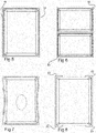
- An open plastic container 1 in the form of a box is shown in fig 1 .
- the box has a bottom portion 3 and first 5, 7 and second 9, 11 pairs of opposing walls rising from the bottom, thereby defining an internal space of the box.
- the box further has flanges, as will be shown, at the upper edges of at least one pair of walls.
- the flanges extend outwards from the interior of the box in a direction substantially parallel or close to parallel with the plane in which the bottom portion 3 extends. This allows the box to be inserted in a drawer frame.
- Such a drawer frame 15 is shown in fig 3 , where five boxes 1 with applied lids 13 are inserted in the frame.
- Fig 4 shows a U shaped guide 17 in the frame, which is adapted to accommodate the flange 19 of the box, in order to support the box in the frame.
- Such frames with guides are well known per se to support containers made of metal wire, metal mesh materials etc.
- the lid 13 of the box is designed to leave an outer portion 21 of the flange 19 free when the lid is applied to the box. This is done along the length flange that engages with the guide 17 in the drawer frame 15. Thus, for instance in the box shown in fig 2 , a portion of the flange is left free along the longer sides of the box, although other variations exist as will be discussed.
- the outer portion 21 of the flanges left free may be at least 7 mm, and about 12 mm is considered suitable for many applications.
- the flange 19 As the outer portion 21 of the flange 19 is left free, the flange is allowed to take up almost the entire height of the guide 17, which means that a stiffer flange can be provided for a given guide dimension.
- a stiff flange is advantageous as it allows the box to be more heavily loaded without bulging, as will be discussed later.
- the lid can in many cases be removed without taking the box 1 out of the drawer frame 15. For instance, if no box is inserted in the middle compartment of the drawer frame in fig 3 , the lid of the box below the middle compartment can easily be removed.
- Figs 5 and 6 illustrates two possible configurations of containers for insertion into a rack.
- the box takes up the full space between two guides and the flanges, indicated with the dashed boxes, of the long edges should be left at least partially free as mentioned above.
- the lid should leave an outer portion of the flanges free along the entire length of the walls of one pair of opposing walls, specifically the flanges intended to engage with guides of a drawer frame.
- the stiffness of the flanges is one important determining factor for the load that can be applied in the box without the box deforming in such a way that it for instance may become stuck in a drawer frame.
- a too heavy load (indicated dashed) makes the box bulge when suspended between the flanges of the long sides.
- the lid design allows the flange to take up most of the inner space of the guide, which provides a stiffer flange. This may be used in combination with the reinforcing flange design to be described later, although this is not necessary.
- Fig 8 illustrates a version of the box with flanges extending only over a part of the periphery.
- the box is intended to be suspended from flanges on its long sides. Even if in most other shown embodiments the flange extend along all four sides of the box, it may be sufficient, as illustrated that the flange extends around the corners 23 of the box, and some distance into the adjacent (in this case short) side.
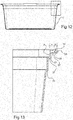
- Fig 9 shows a perspective view of the bottom of a container.
- the flanges may comprise at least one reinforcing subflange 25, that extends from the flange along at least a part thereof, and is directed downwards, i.e. substantially perpendicularly towards the plane in which the bottom portion 3 extends.
- the subflanges may extend about 4.2 mm from the lower surface of the main flange 19.
- lateral reinforcement flanges 29 running perpendicularly to the reinforcement flanges, and connecting the reinforcement flanges 25, 27 to each other and to the adjacent wall of the box.
- Such lateral flanges may be provided at regular intervals over the sides of the box, and also at the corners of the box as shown in fig 11 .
- fig 12 and fig 13 show a cross section through the long sides of a box without a lid.
- fig 12 there is shown a cross section transverse through the long side of the box, and fig 13 shows an enlarged portion, where the flange 19 meets the side wall 7 of the box.
- Fig 13 illustrates how a strong flange may be achieved without providing a thick portions in the box. Thick goods would require substantial periods of time to become fully solid during injection moulding and would therefore imply long cycle times during production.
- the disclosed flange configuration however, becomes very strong without using goods thicknesses exceeding 3.5 mm, even 2.0 mm could be sufficient in many applications.
- the c-c (centre-centre) distance a+b, in the illustrated case, between the box wall 7 and the outer reinforcement flange 25 is about 13 mm.
- the distance a between the box wall 7 and the inner reinforcement flange 27 is about 8 mm.
- the inner reinforcement flange 27 is placed closer to the outer reinforcement flange 25 than to the box wall 7. This has proven to avoid the condition illustrated in fig 7 to a great extent by providing a stiffer flange.
- the ratio (a + b) / a between the sum of the c-c distance a between the wall 7 and the inner flange 27and the c-c distance b between the inner reinforcement flange 27 and the outer reinforcement flange 25 to the distance a is in the range between 1.5 and 1.9. In this illustrated case, the ratio is about 1.6 to 1.7, and this is considered suitable for many applications.
- ledges 31, 33 may be provided in the wall 7, which make the container even stiffer and facilitates nesting of empty containers.
- the present disclosure thus considers a plastic box with a bottom portion and first and second pairs of opposing walls rising from the bottom portion where at least each of the upper edges of the first pair of walls comprise a respective flange that extend outwards in a direction substantially parallel with a plane in which the bottom portion extends, and wherein each flange comprises at least one reinforcing subflange, extending from the flange along at least a part thereof, and being directed towards a plane in which the bottom portion extends.
- each main flange comprises two parallel subflanges and a plurality of lateral reinforcement flanges running perpendicularly to the subflanges and connecting the subflanges to each other and to the walls of the box, and as mentioned above, the aforementioned ratio (a + b) / a may be in the range between 1.5 and 1.9.
Landscapes
- Engineering & Computer Science (AREA)
- Mechanical Engineering (AREA)
- Ceramic Engineering (AREA)
- Rigid Containers With Two Or More Constituent Elements (AREA)
- Closures For Containers (AREA)
- Containers Having Bodies Formed In One Piece (AREA)
- Stackable Containers (AREA)
- Packages (AREA)
Priority Applications (1)
| Application Number | Priority Date | Filing Date | Title |
|---|---|---|---|
| EP18154492.5A EP3357829A1 (en) | 2014-05-14 | 2014-05-14 | Container |
Applications Claiming Priority (2)
| Application Number | Priority Date | Filing Date | Title |
|---|---|---|---|
| EP14168245.0A EP2944582B1 (en) | 2014-05-14 | 2014-05-14 | Combination of a container and a drawer frame. |
| EP18154492.5A EP3357829A1 (en) | 2014-05-14 | 2014-05-14 | Container |
Related Parent Applications (2)
| Application Number | Title | Priority Date | Filing Date |
|---|---|---|---|
| EP14168245.0A Division-Into EP2944582B1 (en) | 2014-05-14 | 2014-05-14 | Combination of a container and a drawer frame. |
| EP14168245.0A Division EP2944582B1 (en) | 2014-05-14 | 2014-05-14 | Combination of a container and a drawer frame. |
Publications (1)
| Publication Number | Publication Date |
|---|---|
| EP3357829A1 true EP3357829A1 (en) | 2018-08-08 |
Family
ID=50732817
Family Applications (2)
| Application Number | Title | Priority Date | Filing Date |
|---|---|---|---|
| EP18154492.5A Withdrawn EP3357829A1 (en) | 2014-05-14 | 2014-05-14 | Container |
| EP14168245.0A Active EP2944582B1 (en) | 2014-05-14 | 2014-05-14 | Combination of a container and a drawer frame. |
Family Applications After (1)
| Application Number | Title | Priority Date | Filing Date |
|---|---|---|---|
| EP14168245.0A Active EP2944582B1 (en) | 2014-05-14 | 2014-05-14 | Combination of a container and a drawer frame. |
Country Status (11)
| Country | Link |
|---|---|
| US (1) | US10906706B2 (enExample) |
| EP (2) | EP3357829A1 (enExample) |
| CN (1) | CN105083690B (enExample) |
| AU (1) | AU2015260999A1 (enExample) |
| DK (1) | DK2944582T3 (enExample) |
| MX (1) | MX2016014831A (enExample) |
| NO (1) | NO2944582T3 (enExample) |
| PL (1) | PL2944582T3 (enExample) |
| RU (1) | RU2016147978A (enExample) |
| TW (1) | TW201605379A (enExample) |
| WO (1) | WO2015173216A1 (enExample) |
Families Citing this family (16)
| Publication number | Priority date | Publication date | Assignee | Title |
|---|---|---|---|---|
| RU2764970C2 (ru) | 2017-10-27 | 2022-01-24 | Элфа Интернешенел Аб | Настенная конфигурируемая система хранения |
| CN108974649A (zh) * | 2018-05-24 | 2018-12-11 | 芜湖蓝天工程塑胶有限公司 | 快速降温的保鲜盒 |
| CN108974540A (zh) * | 2018-05-24 | 2018-12-11 | 芜湖蓝天工程塑胶有限公司 | 手提保鲜盒 |
| CN108974541A (zh) * | 2018-05-24 | 2018-12-11 | 芜湖蓝天工程塑胶有限公司 | 保鲜盒 |
| CN108715279A (zh) * | 2018-05-24 | 2018-10-30 | 芜湖蓝天工程塑胶有限公司 | 保温保鲜盒 |
| CN210539782U (zh) * | 2019-06-18 | 2020-05-19 | 曹欣 | 多功能透气性储物柜 |
| US11284719B2 (en) | 2019-09-13 | 2022-03-29 | Greenheck Racing, Inc. | Drawer assembly having securable guides and related methods |
| SE543835C2 (en) | 2019-12-23 | 2021-08-10 | Elfa Int Ab | Shelf storage system comprising hang standards with screw holes at distances corresponding to desired bracket to bracket distances |
| USD944058S1 (en) * | 2020-03-27 | 2022-02-22 | Xiamen Legenda Electronic Technology Company Limited | Coffee pod storage drawer |
| SE545538C2 (en) | 2020-06-22 | 2023-10-17 | Elfa Int Ab | Mesh container and method for producing a mesh container |
| US11950696B2 (en) * | 2021-02-17 | 2024-04-09 | Robert Allen Short | Modular storage compartments with tri-mode lids |
| US20240324772A1 (en) * | 2021-02-17 | 2024-10-03 | Robert Allen Short | Modular storage compartments with tri-mode lids |
| TWI762379B (zh) * | 2021-07-09 | 2022-04-21 | 永山實業股份有限公司 | 組合式置物層架之籃體軌道組裝結構 |
| US12503812B2 (en) | 2021-11-19 | 2025-12-23 | Sortana Llc | Laundry sorting and processing system and method |
| SE2151577A1 (en) | 2021-12-21 | 2023-06-22 | Elfa Int Ab | Container and method for producing a container |
| TWD230774S (zh) * | 2022-10-31 | 2024-04-11 | 聯府塑膠股份有限公司 苗栗縣銅鑼鄉銅鑼村自強路18號 (中華民國) | 推車之置物籃 |
Citations (4)
| Publication number | Priority date | Publication date | Assignee | Title |
|---|---|---|---|---|
| US3904074A (en) * | 1973-09-27 | 1975-09-09 | Scott Paper Co | Packaging system |
| US4373642A (en) * | 1980-12-04 | 1983-02-15 | Westinghouse Electric Corp. | Material handling tote |
| US4967908A (en) * | 1989-11-17 | 1990-11-06 | The Vollrath Company, Inc. | Apparatus for transporting articles |
| CN201120966Y (zh) * | 2007-12-05 | 2008-09-24 | 常熟龙家居塑料制品有限公司 | 储存盒 |
Family Cites Families (10)
| Publication number | Priority date | Publication date | Assignee | Title |
|---|---|---|---|---|
| FR1464910A (fr) * | 1965-11-26 | 1967-01-06 | Perfectionnements aux emballages | |
| US3484035A (en) * | 1968-01-08 | 1969-12-16 | Dart Ind Inc | Multipurpose container |
| IT8722982V0 (it) * | 1987-12-31 | 1987-12-31 | Metaltex Spa | Scaffaletto smontabile con cestelli estraibili e fiancate mantenute in posizione da uno di detti cestelli non estraibili. |
| JP3091128B2 (ja) * | 1996-02-20 | 2000-09-25 | 岐阜プラスチック工業株式会社 | 収納ケース |
| CN2503006Y (zh) * | 2001-09-28 | 2002-07-31 | 叶凯伦 | 塑料制品补强肋的改良结构 |
| US8006858B2 (en) * | 2001-12-03 | 2011-08-30 | Design Ideas, Ltd. | Method for making mesh containers with a rail and mesh container formed therefrom |
| CA2640959C (en) * | 2006-02-09 | 2011-03-29 | Rubbermaid Incorporated | Storage container and container system |
| NZ578575A (en) * | 2009-04-21 | 2011-01-28 | Decor Corp Pty Ltd | A sealable container with the seal removably attached to the inside of the lid |
| TWM433340U (en) * | 2011-09-14 | 2012-07-11 | Hsin Mao Plastics Co Ltd | Drawer cart having in-mold label |
| KR101338365B1 (ko) * | 2012-05-21 | 2013-12-09 | 정영국 | 밀폐 수납함 |
-
2014
- 2014-05-14 PL PL14168245T patent/PL2944582T3/pl unknown
- 2014-05-14 NO NO14168245A patent/NO2944582T3/no unknown
- 2014-05-14 EP EP18154492.5A patent/EP3357829A1/en not_active Withdrawn
- 2014-05-14 EP EP14168245.0A patent/EP2944582B1/en active Active
- 2014-05-14 DK DK14168245.0T patent/DK2944582T3/en active
-
2015
- 2015-03-16 CN CN201510113336.3A patent/CN105083690B/zh not_active Expired - Fee Related
- 2015-05-12 MX MX2016014831A patent/MX2016014831A/es unknown
- 2015-05-12 WO PCT/EP2015/060429 patent/WO2015173216A1/en not_active Ceased
- 2015-05-12 RU RU2016147978A patent/RU2016147978A/ru not_active Application Discontinuation
- 2015-05-12 US US15/309,111 patent/US10906706B2/en active Active
- 2015-05-12 AU AU2015260999A patent/AU2015260999A1/en not_active Abandoned
- 2015-05-13 TW TW104115259A patent/TW201605379A/zh unknown
Patent Citations (4)
| Publication number | Priority date | Publication date | Assignee | Title |
|---|---|---|---|---|
| US3904074A (en) * | 1973-09-27 | 1975-09-09 | Scott Paper Co | Packaging system |
| US4373642A (en) * | 1980-12-04 | 1983-02-15 | Westinghouse Electric Corp. | Material handling tote |
| US4967908A (en) * | 1989-11-17 | 1990-11-06 | The Vollrath Company, Inc. | Apparatus for transporting articles |
| CN201120966Y (zh) * | 2007-12-05 | 2008-09-24 | 常熟龙家居塑料制品有限公司 | 储存盒 |
Also Published As
| Publication number | Publication date |
|---|---|
| EP2944582B1 (en) | 2018-03-14 |
| US10906706B2 (en) | 2021-02-02 |
| RU2016147978A (ru) | 2018-06-15 |
| EP2944582A1 (en) | 2015-11-18 |
| CN105083690B (zh) | 2018-01-19 |
| NO2944582T3 (enExample) | 2018-08-11 |
| RU2016147978A3 (enExample) | 2018-10-15 |
| AU2015260999A1 (en) | 2016-11-17 |
| WO2015173216A1 (en) | 2015-11-19 |
| MX2016014831A (es) | 2017-06-29 |
| TW201605379A (zh) | 2016-02-16 |
| CN105083690A (zh) | 2015-11-25 |
| DK2944582T3 (en) | 2018-05-28 |
| US20170066566A1 (en) | 2017-03-09 |
| PL2944582T3 (pl) | 2020-07-13 |
Similar Documents
| Publication | Publication Date | Title |
|---|---|---|
| EP2944582B1 (en) | Combination of a container and a drawer frame. | |
| US10028582B2 (en) | Storage system | |
| US3392877A (en) | Container | |
| US9302810B2 (en) | Bakery tray | |
| EP2944581A1 (en) | A lid and a storage system | |
| KR200441019Y1 (ko) | 서랍형 수납장 | |
| JP3209673U (ja) | 棚に出し入れが容易な物品収納トレー | |
| JP2006096366A (ja) | 合成樹脂製容器 | |
| EP2357438A1 (en) | Drawer for refrigerating apparatuses | |
| FI72476C (fi) | Uppbevaringssystem foer engaongsbehaollare. | |
| US20180170666A1 (en) | Waste bin with an injection molded plastic body | |
| CN204923672U (zh) | 拉出盒、应用拉出盒的制冷器具和用于拉出盒的运输堆组 | |
| KR101284004B1 (ko) | 운반상자의 높낮이 조절 트레이 | |
| CA2866924C (en) | Multi-level stacking container | |
| US20240317458A1 (en) | Stackable and/or nestable box | |
| GB2429687A (en) | Stackable and nestable container | |
| KR101187508B1 (ko) | 물품의 투입이 용이하면서 수납공간의 넓은 활용이 가능하며 재 적층이 용이한 다용도 수납함 | |
| KR20240173484A (ko) | 배부름 방지구조를 지닌 플라스틱 상자 | |
| KR20230112909A (ko) | 다기능물품수납함 | |
| RU19378U1 (ru) | Лоток для размещения товаров | |
| KR20210055926A (ko) | 다면 방향을 갖는 서랍장 | |
| KR20110007540U (ko) | 수산물 상자 |
Legal Events
| Date | Code | Title | Description |
|---|---|---|---|
| PUAI | Public reference made under article 153(3) epc to a published international application that has entered the european phase |
Free format text: ORIGINAL CODE: 0009012 |
|
| STAA | Information on the status of an ep patent application or granted ep patent |
Free format text: STATUS: THE APPLICATION HAS BEEN PUBLISHED |
|
| AC | Divisional application: reference to earlier application |
Ref document number: 2944582 Country of ref document: EP Kind code of ref document: P |
|
| AK | Designated contracting states |
Kind code of ref document: A1 Designated state(s): AL AT BE BG CH CY CZ DE DK EE ES FI FR GB GR HR HU IE IS IT LI LT LU LV MC MK MT NL NO PL PT RO RS SE SI SK SM TR |
|
| STAA | Information on the status of an ep patent application or granted ep patent |
Free format text: STATUS: THE APPLICATION IS DEEMED TO BE WITHDRAWN |
|
| 18D | Application deemed to be withdrawn |
Effective date: 20190209 |