EP3357810A1 - Systèmes d'anticipation de la demande d'énergie pour giravion - Google Patents
Systèmes d'anticipation de la demande d'énergie pour giravion Download PDFInfo
- Publication number
- EP3357810A1 EP3357810A1 EP18154777.9A EP18154777A EP3357810A1 EP 3357810 A1 EP3357810 A1 EP 3357810A1 EP 18154777 A EP18154777 A EP 18154777A EP 3357810 A1 EP3357810 A1 EP 3357810A1
- Authority
- EP
- European Patent Office
- Prior art keywords
- power demand
- engine
- demand anticipation
- rotorcraft
- anticipation
- Prior art date
- Legal status (The legal status is an assumption and is not a legal conclusion. Google has not performed a legal analysis and makes no representation as to the accuracy of the status listed.)
- Granted
Links
- 125000004122 cyclic group Chemical group 0.000 claims abstract description 37
- 238000004891 communication Methods 0.000 claims abstract description 7
- RZVHIXYEVGDQDX-UHFFFAOYSA-N 9,10-anthraquinone Chemical compound C1=CC=C2C(=O)C3=CC=CC=C3C(=O)C2=C1 RZVHIXYEVGDQDX-UHFFFAOYSA-N 0.000 claims description 33
- 238000000034 method Methods 0.000 claims description 19
- 238000001514 detection method Methods 0.000 claims description 13
- 238000007493 shaping process Methods 0.000 claims description 5
- 230000003466 anti-cipated effect Effects 0.000 claims description 4
- 230000003416 augmentation Effects 0.000 claims description 3
- 238000001914 filtration Methods 0.000 claims description 3
- 230000000712 assembly Effects 0.000 description 12
- 238000000429 assembly Methods 0.000 description 12
- 230000008859 change Effects 0.000 description 5
- 238000012986 modification Methods 0.000 description 5
- 230000004048 modification Effects 0.000 description 5
- 230000008901 benefit Effects 0.000 description 4
- 230000006870 function Effects 0.000 description 4
- 238000012545 processing Methods 0.000 description 4
- 238000010586 diagram Methods 0.000 description 3
- 239000000446 fuel Substances 0.000 description 3
- 230000004044 response Effects 0.000 description 3
- 230000003247 decreasing effect Effects 0.000 description 2
- 238000011161 development Methods 0.000 description 2
- 230000005055 memory storage Effects 0.000 description 2
- 230000002123 temporal effect Effects 0.000 description 2
- 230000007704 transition Effects 0.000 description 2
- 230000003321 amplification Effects 0.000 description 1
- 230000003190 augmentative effect Effects 0.000 description 1
- 238000004590 computer program Methods 0.000 description 1
- 230000007812 deficiency Effects 0.000 description 1
- 238000013461 design Methods 0.000 description 1
- 230000000694 effects Effects 0.000 description 1
- 230000003278 mimic effect Effects 0.000 description 1
- 238000003199 nucleic acid amplification method Methods 0.000 description 1
- 230000003287 optical effect Effects 0.000 description 1
- 230000008569 process Effects 0.000 description 1
- 230000002441 reversible effect Effects 0.000 description 1
- 238000006467 substitution reaction Methods 0.000 description 1
- 238000013519 translation Methods 0.000 description 1
Images


Classifications
-
- B—PERFORMING OPERATIONS; TRANSPORTING
- B64—AIRCRAFT; AVIATION; COSMONAUTICS
- B64D—EQUIPMENT FOR FITTING IN OR TO AIRCRAFT; FLIGHT SUITS; PARACHUTES; ARRANGEMENT OR MOUNTING OF POWER PLANTS OR PROPULSION TRANSMISSIONS IN AIRCRAFT
- B64D35/00—Transmitting power from power plants to propellers or rotors; Arrangements of transmissions
-
- B—PERFORMING OPERATIONS; TRANSPORTING
- B64—AIRCRAFT; AVIATION; COSMONAUTICS
- B64D—EQUIPMENT FOR FITTING IN OR TO AIRCRAFT; FLIGHT SUITS; PARACHUTES; ARRANGEMENT OR MOUNTING OF POWER PLANTS OR PROPULSION TRANSMISSIONS IN AIRCRAFT
- B64D31/00—Power plant control systems; Arrangement of power plant control systems in aircraft
-
- B—PERFORMING OPERATIONS; TRANSPORTING
- B64—AIRCRAFT; AVIATION; COSMONAUTICS
- B64C—AEROPLANES; HELICOPTERS
- B64C13/00—Control systems or transmitting systems for actuating flying-control surfaces, lift-increasing flaps, air brakes, or spoilers
- B64C13/24—Transmitting means
- B64C13/38—Transmitting means with power amplification
- B64C13/50—Transmitting means with power amplification using electrical energy
- B64C13/503—Fly-by-Wire
-
- B—PERFORMING OPERATIONS; TRANSPORTING
- B64—AIRCRAFT; AVIATION; COSMONAUTICS
- B64C—AEROPLANES; HELICOPTERS
- B64C27/00—Rotorcraft; Rotors peculiar thereto
- B64C27/04—Helicopters
-
- B—PERFORMING OPERATIONS; TRANSPORTING
- B64—AIRCRAFT; AVIATION; COSMONAUTICS
- B64D—EQUIPMENT FOR FITTING IN OR TO AIRCRAFT; FLIGHT SUITS; PARACHUTES; ARRANGEMENT OR MOUNTING OF POWER PLANTS OR PROPULSION TRANSMISSIONS IN AIRCRAFT
- B64D31/00—Power plant control systems; Arrangement of power plant control systems in aircraft
- B64D31/02—Initiating means
- B64D31/06—Initiating means actuated automatically
-
- F—MECHANICAL ENGINEERING; LIGHTING; HEATING; WEAPONS; BLASTING
- F02—COMBUSTION ENGINES; HOT-GAS OR COMBUSTION-PRODUCT ENGINE PLANTS
- F02C—GAS-TURBINE PLANTS; AIR INTAKES FOR JET-PROPULSION PLANTS; CONTROLLING FUEL SUPPLY IN AIR-BREATHING JET-PROPULSION PLANTS
- F02C9/00—Controlling gas-turbine plants; Controlling fuel supply in air- breathing jet-propulsion plants
- F02C9/26—Control of fuel supply
- F02C9/28—Regulating systems responsive to plant or ambient parameters, e.g. temperature, pressure, rotor speed
-
- G—PHYSICS
- G05—CONTROLLING; REGULATING
- G05B—CONTROL OR REGULATING SYSTEMS IN GENERAL; FUNCTIONAL ELEMENTS OF SUCH SYSTEMS; MONITORING OR TESTING ARRANGEMENTS FOR SUCH SYSTEMS OR ELEMENTS
- G05B13/00—Adaptive control systems, i.e. systems automatically adjusting themselves to have a performance which is optimum according to some preassigned criterion
-
- F—MECHANICAL ENGINEERING; LIGHTING; HEATING; WEAPONS; BLASTING
- F05—INDEXING SCHEMES RELATING TO ENGINES OR PUMPS IN VARIOUS SUBCLASSES OF CLASSES F01-F04
- F05D—INDEXING SCHEME FOR ASPECTS RELATING TO NON-POSITIVE-DISPLACEMENT MACHINES OR ENGINES, GAS-TURBINES OR JET-PROPULSION PLANTS
- F05D2220/00—Application
- F05D2220/30—Application in turbines
- F05D2220/32—Application in turbines in gas turbines
- F05D2220/323—Application in turbines in gas turbines for aircraft propulsion, e.g. jet engines
-
- F—MECHANICAL ENGINEERING; LIGHTING; HEATING; WEAPONS; BLASTING
- F05—INDEXING SCHEMES RELATING TO ENGINES OR PUMPS IN VARIOUS SUBCLASSES OF CLASSES F01-F04
- F05D—INDEXING SCHEME FOR ASPECTS RELATING TO NON-POSITIVE-DISPLACEMENT MACHINES OR ENGINES, GAS-TURBINES OR JET-PROPULSION PLANTS
- F05D2270/00—Control
- F05D2270/30—Control parameters, e.g. input parameters
- F05D2270/313—Air temperature
Definitions
- the present disclosure relates, in general, to power demand anticipation systems for use on rotorcraft and, in particular, to power demand anticipation systems capable of utilizing rotorcraft data from various sources, including, but not limited to, cyclic control position, to anticipate the power demand on an engine.
- the power demand on the engine of a rotorcraft can vary over time based on the operation being performed. For example, an increased power demand may be placed on an engine during helicopter takeoff or during some maneuvers, such as a fixed collective takeoff. Such increased power demand can result in low rotor rotational speed, or "rotor droop," in which the engine cannot drive the rotor at sufficient speed to maintain flight.
- Some rotorcraft lack the ability to anticipate power demand and must wait for an error in rotor speed or torque to occur before adjusting engine output.
- Power demand anticipation can help maintain rotor speed within a selected range no matter the operation being performed by the rotorcraft, which directly impacts rotor speed performance.
- Some helicopters utilize the collective control of their main rotor blades to anticipate power demand on the engine. When such a helicopter experiences a change in power demand due to factors unrelated to the collective control, however, the helicopter may fail to anticipate or provide a timely power output response. Accordingly, a need has arisen for a power demand anticipation system that utilizes sensor data, non-collective input and/or other data to effectively and efficiently anticipate power demand on an engine to improve rotorcraft performance.
- the present disclosure is directed to a power demand anticipation system for a rotorcraft including an engine subsystem having an engine with a power output.
- the power demand anticipation system also includes one or more sensors including a cyclic control sensor.
- the one or more sensors are operable to detect one or more flight parameters of the rotorcraft to form sensor data including a cyclic control position.
- a power demand anticipation module is in data communication with the engine subsystem and the one or more sensors.
- the power demand anticipation module is operable to anticipate a power demand of the engine using the sensor data to form a power demand anticipation signal.
- the engine subsystem is operable to adjust the power output of the engine based on the power demand anticipation signal received from the power demand anticipation module.
- the engine subsystem may adjust the power output of the engine before the power demand anticipated by the power demand anticipation module is applied to the engine.
- the power demand anticipation system may include one or more actuators each operable to move a portion of the rotorcraft, and a control laws module operable to generate one or more commands to move the one or more actuators based on the sensor data to form one or more actuator position commands.
- the power demand anticipation module may be operable to anticipate the power demand of the engine using the one or more actuator position commands to form the power demand anticipation signal.
- the one or more actuators may include one or more main rotor actuators.
- the power demand anticipation system may include one or more actuators each positionable between a plurality of actuator positions to move a portion of the rotorcraft based on the sensor data.
- the power demand anticipation module may be operable to anticipate the power demand of the engine using the actuator positions to form the power demand anticipation signal.
- the power demand anticipation system may include a maneuver detection module operable to detect a maneuver performed by the rotorcraft based on the sensor data.
- the power demand anticipation module may be operable to anticipate the power demand of the engine based on the maneuver to form the power demand anticipation signal.
- the maneuver detected by the maneuver detection module may be a fixed collective takeoff or translating off an elevated platform.
- the one or more sensors may include an altitude sensor and the maneuver detection module may use altitude data from the altitude sensor to detect the rotorcraft translating off the elevated platform.
- the engine subsystem may include an engine interface having a governor, the engine interface receiving the power demand anticipation signal for utilization by the governor to adjust the power output of the engine.
- the power demand anticipation module may be implemented on a flight control computer.
- the one or more sensors may include at least one of an airspeed sensor, an altitude sensor, a wind velocity sensor or a collective control sensor.
- the present disclosure is directed to a method for anticipating power demand for an engine of a rotorcraft.
- the method includes receiving one or more flight parameters from one or more sensors to form sensor data; anticipating a power demand of the engine using the sensor data to form a power demand anticipation signal; and sending the power demand anticipation signal to an engine subsystem to enable the engine subsystem to adjust a power output of the engine based on the power demand anticipation signal.
- the method may include generating one or more commands to move one or more actuators of the rotorcraft based on the sensor data to form one or more actuator position commands; wherein anticipating the power demand of the engine using the sensor data to form the power demand anticipation signal further comprises anticipating the power demand of the engine using the one or more actuator position commands to form the power demand anticipation signal.
- the method may include positioning one or more actuators of the rotorcraft into one of a plurality of actuator positions to move a portion of the rotorcraft using the sensor data; wherein anticipating the power demand of the engine using the sensor data to form the power demand anticipation signal further comprises anticipating the power demand of the engine using the actuator position to form the power demand anticipation signal.
- the method may include filtering the power demand anticipation signal to remove a steady component and shaping the power demand anticipation signal to match a droop associated with the one or more flight parameters; scaling a cyclic control position to expected revolutions per minute error; or adjusting the power demand anticipation signal based on an ambient condition including at least one of airspeed, altitude or air temperature.
- the present disclosure is directed to a rotorcraft including a fuselage, a rotor hub assembly rotatable relative to the fuselage, an engine subsystem including an engine having a power output to provide rotational energy to the rotor hub assembly and one or more sensors including a cyclic control sensor.
- the one or more sensors are operable to detect one or more flight parameters of the rotorcraft to form sensor data including a cyclic control position.
- the rotorcraft also includes a flight control computer in data communication with the engine subsystem and the one or more sensors.
- the flight control computer includes a power demand anticipation module operable to anticipate a power demand of the engine using the sensor data to form a power demand anticipation signal.
- the engine subsystem is operable to adjust the power output of the engine based on the power demand anticipation signal received from the power demand anticipation module.
- the rotorcraft may be a fly-by-wire rotorcraft.
- the flight control computer may be implemented using a full authority plus augmentation flight control system or a three-loop flight control system.
- Rotorcraft 10 has a rotor hub assembly 12, which includes a plurality of rotor blade assemblies 14.
- Rotor hub assembly 12 is rotatable relative to a fuselage 16 of rotorcraft 10.
- Rotor hub assembly 12 is supported atop rotorcraft 10 by a mast 18.
- a landing gear system 20 provides ground support for rotorcraft 10.
- the pitch of rotor blade assemblies 14 can be collectively and/or cyclically manipulated to selectively control direction, thrust and lift of rotorcraft 10.
- a collective control 22 may be used to control the altitude of rotorcraft 10 by simultaneously changing the pitch angle of all rotor blade assemblies 14 independently of their position.
- a cyclic control 24 may be used to control the attitude and airspeed of rotorcraft 10 by controlling the pitch of rotor blade assemblies 14 cyclically. More specifically, the relative pitch, or feathering angle, of each of rotor blade assemblies 14 will vary as they rotate. Unless otherwise indicated, as used herein, "or" does not require mutual exclusivity. The variation in relative pitch has the effect of varying the angle of attack of, and thus the lift generated by, each rotor blade assembly 14 as it rotates.
- a rotor disk which is part of a main rotor actuation assembly 26 to which rotor blade assemblies 14 are coupled, tilts forward or backward and thrust is produced in the forward direction or backward direction, respectively.
- the rotor disk tilts to the right or left and thrust is produced in the right direction or left direction, respectively.
- Rotorcraft 10 implements a power demand anticipation system that anticipates power demand on an engine 28.
- Engine 28 generates a power output to provide rotational energy to rotor hub assembly 12.
- the power demand anticipation system of the illustrative embodiments utilizes data from a wide variety of sources to determine the power demand on engine 28 before such power demand actually occurs.
- Rotorcraft 10 includes a flight control computer 30 implementing a power demand anticipation module 32.
- rotorcraft 10 is a fly-by-wire rotorcraft.
- power demand anticipation module 32 may use sensor data from sensors 34, 36, 38 to anticipate a power demand on engine 28. Sensors 34, 36, 38 detect various flight parameters of rotorcraft 10, such as the position or motion of cyclic control 24, airspeed, altitude and/or wind velocity, among others.
- power demand anticipation module 32 may utilize commands issued by a control laws module implemented by flight control computer 30 to anticipate a power demand on engine 28.
- the commands utilized by power demand anticipation module 32 may be actuator position commands, based on control laws, that move main rotor actuation assembly 26 and/or other actuators on rotorcraft 10 based on the sensor data from sensors 34, 36, 38.
- Non-limiting examples of actuator position commands and other commands that may be utilized by power demand anticipation module 32 include cyclic actuator demands, collective actuator commands, any combination of rotor actuator commands, as may be used in mixed systems, directional actuator commands or the like.
- power demand anticipation module 32 uses the positions of the actuators in rotorcraft 10, including main rotor actuation assembly 26, to anticipate the power demand on engine 28.
- power demand anticipation module 32 may also use the positions of actuators for a tail rotor 40 or any movable control surfaces on rotorcraft 10.
- the power demand anticipation system implemented by rotorcraft 10 may utilize a wide variety of data sources to anticipate power demand on engine 28, thereby improving rotorcraft performance and preventing drooping or overshooting of rotor hub assembly 12 when the power demand on engine 28 changes.
- rotorcraft 10 is merely illustrative of a variety of aircraft that can implement the embodiments disclosed herein.
- the power demand anticipation system may be utilized on any aircraft having one or more engines with a changing power demand.
- Other aircraft implementations can include hybrid aircraft, tiltrotor aircraft, tiltwing aircraft, quad tiltrotor aircraft, unmanned aircraft, gyrocopters, airplanes and the like.
- the power demand anticipation systems disclosed herein can be integrated into a variety of aircraft configurations. It should be appreciated that even though aircraft are particularly well-suited to implement the embodiments of the present disclosure, non-aircraft vehicles and devices can also implement the embodiments.
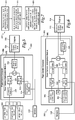
- Power demand anticipation system 100 is implemented on rotorcraft 102 and includes power demand anticipation module 104, executed on flight control computer 106, in data communication with one or more sensors 108, one or more actuators 110 and an engine subsystem 112 that includes an engine interface 114 and one or more engines 116.
- Flight control computer 106 includes a control laws module 118 that generates actuator position commands 120 to move actuators 110 based on sensor data 122 from sensors 108.
- Power demand anticipation module 104 uses sensor data 122 from sensors 108, actuator position commands 120 from control laws module 118, actuator positions 124 of actuators 110 or any combination thereof to anticipate the power demand from engine 116 to form a power demand anticipation signal 126 that is transmitted to engine interface 114 so that governor 128 can adjust the power output of engine 116.
- Governor 128 adjusts the power output of engine 116 before application of the power demand anticipated by power demand anticipation module 104 to engine 116 to maintain the rotational speed of one or more rotors of rotorcraft 102 within a predetermined range.
- Sensors 108 detect flight parameters of rotorcraft 102 to form sensor data 122 that is utilized by power demand anticipation module 104, either directly or indirectly.
- Sensors 108 may include a cyclic control sensor 130 that detects the position or motion of a cyclic control, which may form part of sensor data 122 transmitted to power demand anticipation module 104.
- Sensors 108 may include an airspeed sensor 132, which may utilize a doppler radar, global positioning satellites or other airspeed detection techniques.
- Sensors 108 may also include an altitude sensor 134, such as a radar altimeter, an attitude sensor 136 and/or a wind velocity sensor 138.
- Sensors 108 may further include a collective control sensor 140 that detects a position or movement of the collective control of rotorcraft 102.
- sensors 108 that may be used by power demand anticipation system 100 are numerous, non-limiting examples of which include a weight sensor, such as a cargo weight sensor, a rotor speed sensor, an NP sensor, a nacelle tilt angle sensor, a helicopter or tiltrotor aircraft pylon angle sensor, a power turbine output speed sensor, a gas temperature sensor, a throttle position sensor, a compressor speed sensor, an engine torque output sensor, an actuator position sensor, a pressure altitude sensor, a compressor air temperature sensor, a fuel metering valve position sensor or the like.
- a weight sensor such as a cargo weight sensor, a rotor speed sensor, an NP sensor, a nacelle tilt angle sensor, a helicopter or tiltrotor aircraft pylon angle sensor, a power turbine output speed sensor, a gas temperature sensor, a throttle position sensor, a compressor speed sensor, an engine torque output sensor, an actuator position sensor, a pressure altitude sensor, a compressor air temperature sensor, a fuel metering valve position sensor or the like.
- Control laws module 118 may generate commands to maintain a suitable yaw, pitch and roll of rotorcraft 102, as well as issue commands to maintain the power output required by engine 116 to maintain these three axes. Control laws module 118 may also issue other commands such as a G command, pitch rate feedback or C command, to regulate flight of rotorcraft 102.
- Actuators 110 may include any actuator that moves a portion of rotorcraft 102, such as rotor blade assemblies 144, based on sensor data 122. Actuators 110 may each be movable between a plurality of actuator positions 124. Actuators 110 may include main rotor actuators that are operable to adjust the pitch angle of rotor blade assemblies 144, either collectively or cyclically. Non-limiting examples of other types of actuators 110 include tail rotor actuators or control surface actuators.
- power demand anticipation module 104 anticipates a power demand on engine 116 using sensor data 122 to form power demand anticipation signal 126, which is received by engine interface 114 and used by governor 128 to adjust the power output of engine 116.
- power demand anticipation module 104 may receive sensor data 122 that includes a cyclic control position, detected by cyclic control sensor 130, which adjusts the cyclic pitch of rotor blade assemblies 144 such that an increased power output is demanded from engine 116.
- power demand anticipation signal 126 causes engine interface 114 to increase the power output of engine 116.
- power demand anticipation module 104 may indirectly use sensor data 122 via control laws module 118, thus utilizing any feedback terms issued by control laws module 118.
- power demand anticipation module 104 may anticipate the power demand from engine 116 using actuator position commands 120, which may be derived from sensor data 122 and utilize feedback terms, to form power demand anticipation signal 126.
- power demand anticipation module 104 may indirectly utilize sensor data 122 by anticipating the power demand from engine 116 using actuator positions 124 to form power demand anticipation signal 126.
- the actuator positions 124 may be based on sensor data 122 including, but not limited to, cyclic control sensor 130 or collective control sensor 140.
- sensor data 122 is generated by sensors 108 before actuator position commands 120 are generated by control laws module 118, and actuator position commands 120 are generated before actuators 110 move into actuator positions 124. Therefore, in some embodiments it may be desirable to utilize data earlier in the temporal chain of events to provide additional time for engine 116 to meet the power demand indicated by power demand anticipation signal 126.
- Power demand anticipation module 104 may also compensate for increases in power demand due to inputs in various axes, such as laterally or directionally, with differing ambient condition or vehicle state compensation schedules.
- power demand anticipation module 104 may filter power demand anticipation signal 126 to remove one or more steady components, and/or shape power demand anticipation signal 126 to match a droop or overshoot associated with one or more flight parameters detected by sensors 108.
- Power demand anticipation module 104 may also adjust power demand anticipation signal 126 based on an ambient condition, such as altitude data from altitude sensor 134 or airspeed data from airspeed sensor 132.
- power demand anticipation module 104 may scale the cyclic control position to nominal horsepower or expected revolutions per minute error.
- power demand anticipation module 104 in generating power demand anticipation signal 126, may give differing weights to sensor data 122, actuator position commands 120 and actuator positions 124 according to a weighting algorithm.
- Power demand anticipation module 104 may also give differing weights to the data provided by the various sensors 108. For example, power demand anticipation module 104 may weigh the data from each of cyclic control sensor 130, altitude sensor 134 and collective control sensor 140 differently when generating power demand anticipation signal 126.
- Power demand anticipation system 100 may also include a maneuver detection module 142 that detects a maneuver performed by rotorcraft 102 based on sensor data 122.
- power demand anticipation module 104 may indirectly use sensor data 122 to form power demand anticipation signal 126 by processing the maneuver detected by maneuver detection module 142.
- Figures 3A-3B illustrate one example scenario in which the maneuver detection module 142 may be utilized.
- rotorcraft 102 is performing a fixed collective takeoff maneuver.
- a fixed collective takeoff is a takeoff from a steady or in-ground-effect hover, as shown in figure 3A , typically at an altitude below the height-velocity diagram for rotorcraft 102 and without any collective variation.
- a fixed collective takeoff is typically accomplished by a slight forward cyclic position to establish a forward velocity 146 with minimal altitude loss. At some forward velocity 146, translational lift occurs to permit takeoff, as shown in figure 3B . During the time between the cyclic movement and altitude increase caused by the translational lift, rotorcraft 102 may not contact the ground. Because there is no change in the collective position of rotor blade assemblies 144 during a fixed collective takeoff, previous power demand anticipation systems that utilize only collective control fail to anticipate the additional power demand required during a fixed collective takeoff, causing rotor droop and other performance deficiencies.
- a power demand change may be anticipated by power demand anticipation module 104 based on sensor data 122 from cyclic control sensor 130, airspeed sensor 132, a ground speed sensor or any combination thereof.
- Maneuver detection module 142 may use these flight parameters to make a determination that rotorcraft 102 is performing a fixed collective takeoff, and such determination may be used by power demand anticipation module 104 to form power demand anticipation signal 126.
- Figures 4A-4B illustrate rotorcraft 102 translating off of elevated platform 148.
- rotorcraft 102 In translating off elevated platform 148, rotorcraft 102 rapidly transitions from an in-ground-effect hover, as shown in figure 4A , to an out-of-ground-effect hover, as shown in figure 4B .
- Such a transition causes an increase in power demand from engine 116.
- Maneuver detection module 142 may detect a sudden change in radar altitude from altitude sensor 134 in transitioning over the edge of elevated platform 148, indicating a pending increase in power demand due to rotorcraft 102 transitioning from in-ground-effect hover to out-of-ground-effect hover.
- Power demand 150 during the in-ground-effect hover shown in figure 4A is less than power demand 152 required during the out-of-ground-effect hover shown in figure 4B , as graphically shown in figure 4C .
- Power demand anticipation module 104 may anticipate this increased power demand shown in figure 4C by generating power demand anticipation signal 126 in response to maneuver detection module 142 detecting a translation off of elevated platform 148 so that engine 116 may increase its power output accordingly.
- power demand anticipation systems that are limited to utilizing only collective control when anticipating power demand may fail to adequately anticipate power demand in various operational scenarios, leading to an undesirable reliance on error in rotor speed or torque before adjusting the power output of an engine.
- power demand anticipation system 100 may anticipate the power demand from engine 116 in a timely, accurate and more efficient manner to provide a performance benefit for rotorcraft 102.
- power demand anticipation system 100 processes and computes power demand anticipation signal 126 at flight control computer 106 rather than at engine subsystem 112, anticipation processing is performed on the front end rather than the back end, thus allowing power demand anticipation module 104 to be retrofitted onto existing engines on various aircraft.
- Such front end processing may also provide a temporal advantage by anticipating the power demand on engine 116 at an earlier time.
- Power demand anticipation signal 126 may also be sent on the same channel or bus used by existing engine interfaces or electronic engine control units to receive a collective input, thus allowing power demand anticipation module 104 to be retrofitted or used with such prior engine interfaces 114 or electronic engine control units.
- power demand anticipation signal 126 may be transmitted on an ARINC-429 bus.
- actuator position commands 120 may be computed at 50 hertz and power demand anticipation signal 126 may be transmitted at 50 hertz, although any frequency is contemplated within the illustrative embodiments that allows for effective power demand anticipation.
- flight control computer 106 may be part of a triplex system. In other non-limiting examples, flight control computer 106 may be part of a duplex or quad system.
- Power demand anticipation module 104 may be software or firmware implemented on flight control computer 106, and/or may incorporate or utilize a portion of the hardware components of flight control computer 106. While power demand anticipation system 100 is shown to be implemented in a fly-by-wire environment, power demand anticipation system 100 may also be utilized in other flight control systems, such as a conventional mechanical flight control system, an augmented mechanical flight control system or a full authority plus augmentation flight control system.
- Power demand anticipation system 100 may also be implemented on a variety of fly-by-wire flight control systems, including fly-by-wire control systems that have only basic or direct control laws that mimic a mechanical flight control system as a reversionary mode or for improved ballistic tolerance. Power demand anticipation system 100 may also be utilized in a model-following fly-by-wire flight control system or a flight control system with advanced control laws such as a three-loop flight control system.
- governor 128 may include a fuel flow module that regulates the amount of fuel supply to engine 116, thereby controlling the power output of engine 116.
- Power demand anticipation module 202 is implemented on flight control computer 204 to anticipate the power demand on engines 206 based on left, right and aft main rotor actuators 208, 210, 212, sensor data from sensors 214 and commands issuing from control laws module 216.
- Gain module 222 receives commands from control laws module 216 and sensor data from sensors 214 and may apply a gain scheduling term thereto.
- the gain provided by gain modules 220, 222 may be any amplification or attenuation applied to the forward signal to achieve a desired response.
- Output from gain modules 220, 222 may be combined and processed through a shaping module 224, which may shape the incoming signal to form a final power demand anticipation signal that is transmitted to electronic engine control units 226 and used to adjust the power output of engines 206.
- power demand anticipation system 200 may provide looser control at low speeds for improved performance, and tighter control at high speeds for reduced loads.
- gain scheduling terms provided by gain modules 220, 222 may be based on airspeed, tight/loose mode or other conditions.
- power demand anticipation system 200 may also include a collective compensation baseline, as well as shaping networks or schedules on collective position or washed out cyclic at low airspeeds.
- a power demand anticipation system is schematically illustrated and generally designated 300.
- Power demand anticipation module 302 implemented on flight control computer 304, utilizes collective control laws 306, non-collective control laws 308 and sensor data from sensors 310 to generate and transmit a power demand anticipation signal, and a derivative thereof, to electronic engine control units 312 that is used to adjust the power output of engines 314.
- Collective control laws 306 may be processed according to a scheduling term of lookup table 316, while non-collective control laws 308 and sensor data from sensors 310 may be processed by gain module 318.
- Hd including density altitude, compensation 320, 322 may be applied before combining the signals to produce the power demand anticipation signal that is transmitted to electronic engine control units 312.
- derivative module 324 generates a derivative of the power demand anticipation signal and supplies it to electronic engine control units 312.
- Electronic engine control units 312 may then use the power demand anticipation signal, and the derivative thereof, to adjust the power output of engines 314.
- a method for anticipating power demand for an engine of a rotorcraft is illustrated as flowchart 400.
- the method includes receiving one or more flight parameters from one or more sensors to form sensor data (step 402).
- the method includes anticipating a power demand of the engine using the sensor data to form a power demand anticipation signal (step 404).
- the method also includes sending the power demand anticipation signal to an engine subsystem to enable the engine subsystem to adjust the power output of the engine based on the power demand anticipation signal (step 406).
- the method may also include generating one or more commands to move one or more actuators of the rotorcraft based on the sensor data to form one or more actuator position commands, and step 404 may include anticipating the power demand of the engine using the one or more actuator position commands to form the power demand anticipation signal.
- the method may include positioning one or more actuators of the rotorcraft into one of a plurality of actuator positions to move a portion of the rotorcraft using the sensor data, and step 404 may include anticipating the power demand of the engine using the actuator position to form the power demand anticipation signal.
- step 404 may include filtering the power demand anticipation signal to remove a steady component and/or shaping the power demand anticipation signal to match a droop associated with one or more flight parameters. In other embodiments, step 404 may include adjusting the power demand anticipation signal based on an ambient condition including at least one of airspeed, altitude or air temperature. In embodiments in which the rotorcraft sensors include a cyclic control sensor and the sensor data includes a cyclic control position, step 404 may include scaling the cyclic control position to expected revolutions per minute error.
- each block in the flowchart or block diagrams may represent a module, segment, or portion of code, which comprises one or more executable instructions for implementing the specified function or functions.
- the function or functions noted in the block may occur out of the order noted in the figures. For example, in some cases, two blocks shown in succession may be executed substantially concurrently, or the blocks may sometimes be executed in the reverse order, depending upon the functionality involved.
- the flight control computers of the present embodiments preferably include computing elements such as non-transitory computer readable storage media that include computer instructions executable by processors for controlling flight operations.
- the computing elements may be implemented as one or more general-purpose computers, special purpose computers or other machines with memory and processing capability.
- the computing elements may include one or more memory storage modules including, but is not limited to, internal storage memory such as random access memory, non-volatile memory such as read only memory, removable memory such as magnetic storage memory, optical storage, solid-state storage memory or other suitable memory storage entity.
- the computing elements may be implemented as microprocessor-based systems operable to execute program code in the form of machine-executable instructions.
- the computing elements may be selectively connectable to other computer systems via a proprietary encrypted network, a public encrypted network, the Internet or other suitable communication network that may include both wired and wireless connections.
Landscapes
- Engineering & Computer Science (AREA)
- Aviation & Aerospace Engineering (AREA)
- Mechanical Engineering (AREA)
- Automation & Control Theory (AREA)
- Chemical & Material Sciences (AREA)
- Combustion & Propulsion (AREA)
- General Engineering & Computer Science (AREA)
- Artificial Intelligence (AREA)
- Health & Medical Sciences (AREA)
- Computer Vision & Pattern Recognition (AREA)
- Evolutionary Computation (AREA)
- Medical Informatics (AREA)
- Software Systems (AREA)
- Physics & Mathematics (AREA)
- General Physics & Mathematics (AREA)
- Feedback Control In General (AREA)
Applications Claiming Priority (1)
| Application Number | Priority Date | Filing Date | Title |
|---|---|---|---|
| US15/424,801 US10287026B2 (en) | 2017-02-04 | 2017-02-04 | Power demand anticipation systems for rotorcraft |
Publications (2)
| Publication Number | Publication Date |
|---|---|
| EP3357810A1 true EP3357810A1 (fr) | 2018-08-08 |
| EP3357810B1 EP3357810B1 (fr) | 2019-07-17 |
Family
ID=61132349
Family Applications (1)
| Application Number | Title | Priority Date | Filing Date |
|---|---|---|---|
| EP18154777.9A Active EP3357810B1 (fr) | 2017-02-04 | 2018-02-01 | Systèmes d'anticipation de la demande d'énergie pour giravion |
Country Status (3)
| Country | Link |
|---|---|
| US (1) | US10287026B2 (fr) |
| EP (1) | EP3357810B1 (fr) |
| CN (1) | CN108394565B (fr) |
Cited By (2)
| Publication number | Priority date | Publication date | Assignee | Title |
|---|---|---|---|---|
| US20220178311A1 (en) * | 2019-04-01 | 2022-06-09 | Safran Helicopter Engines | Method and system for regulating a non-propulsion electrical generation turbomachine |
| EP4216496A1 (fr) * | 2022-01-20 | 2023-07-26 | Pratt & Whitney Canada Corp. | Procédé et système de transmission de données à partir d'un moteur d'aéronef |
Families Citing this family (12)
| Publication number | Priority date | Publication date | Assignee | Title |
|---|---|---|---|---|
| US11247782B2 (en) * | 2018-09-21 | 2022-02-15 | Textron Innovations Inc. | System and method for controlling rotorcraft |
| US11299286B2 (en) | 2019-05-15 | 2022-04-12 | Pratt & Whitney Canada Corp. | System and method for operating a multi-engine aircraft |
| US11479348B2 (en) | 2019-08-31 | 2022-10-25 | Textron Innovations Inc. | Power management systems for multi engine rotorcraft |
| US11345483B2 (en) * | 2019-10-23 | 2022-05-31 | The Boeing Company | Rotorcraft-mounted rotor blade collision warning system and method for alerting a rotorcraft crew member of a potential collision of a rotor blade |
| CN111413997B (zh) * | 2020-04-14 | 2023-08-22 | 中国人民解放军32180部队 | 高抗风倾转旋翼系留无人机及其飞行控制方法 |
| CN112141350B (zh) * | 2020-09-25 | 2022-12-30 | 中国直升机设计研究所 | 一种直升机地面开车方法 |
| CN112799419A (zh) * | 2020-12-31 | 2021-05-14 | 广州极飞科技股份有限公司 | 用于双旋翼无人机的控制方法、装置、无人机和存储介质 |
| US11208200B1 (en) | 2021-05-14 | 2021-12-28 | Beta Air, Llc | Systems and methods for fly-by-wire reversionary flight control |
| CN113212770B (zh) * | 2021-05-25 | 2023-05-05 | 象限空间(天津)科技有限公司 | 飞行器动力装置控制系统 |
| US11873081B2 (en) | 2021-06-09 | 2024-01-16 | Textron Innovations Inc. | Supplemental engine power control |
| US11447244B1 (en) * | 2021-06-29 | 2022-09-20 | Beta Air, Llc | System and method for airspeed estimation utilizing propulsor data in electric vertical takeoff and landing aircraft |
| US20240017823A1 (en) * | 2022-07-18 | 2024-01-18 | Textron Innovations Inc. | Optimizing usage of supplemental engine power |
Citations (4)
| Publication number | Priority date | Publication date | Assignee | Title |
|---|---|---|---|---|
| WO1993004418A1 (fr) * | 1991-08-27 | 1993-03-04 | United Technologies Corporation | Commande du moteur d'un helicoptere avec anticipation du tangage cyclique lateral |
| US20080283671A1 (en) * | 2007-05-18 | 2008-11-20 | Igor Cherepinsky | Engine anticipation for rotary-wing aircraft |
| EP2101053A2 (fr) * | 2008-03-11 | 2009-09-16 | Honeywell International Inc. | Système et procédé de contrôle de la compensation de prise de mouvement collectif fixe d'un moteur à turbine à gaz |
| US20130291550A1 (en) * | 2011-10-05 | 2013-11-07 | Engineered Propulsion Systems, Inc. | Aero compression combustion drive assembly control system |
Family Cites Families (13)
| Publication number | Priority date | Publication date | Assignee | Title |
|---|---|---|---|---|
| GB1515164A (en) * | 1975-09-16 | 1978-06-21 | Plessey Co Ltd | Guidance systems |
| US4600870A (en) * | 1983-11-17 | 1986-07-15 | United Technologies Corporation | Dual controller position control system |
| US5429089A (en) * | 1994-04-12 | 1995-07-04 | United Technologies Corporation | Automatic engine speed hold control system |
| US5901272A (en) * | 1996-10-24 | 1999-05-04 | The United States Of America As Represented By The Secretary Of The Navy | Neural network based helicopter low airspeed indicator |
| DE10001282C2 (de) * | 2000-01-14 | 2001-10-25 | Lfk Gmbh | Verfahren zur autonomen Detektion von Hubschraubern |
| US6729139B2 (en) * | 2001-09-26 | 2004-05-04 | Goodrich Pump & Engine Control Systems, Inc. | Engine control system |
| CA2585105C (fr) | 2004-11-08 | 2015-04-21 | Bell Helicopter Textron Inc. | Systeme de commande de vol faisant appel a trois boucles de commande |
| US7873445B2 (en) | 2007-03-26 | 2011-01-18 | Bell Helicopter Textron, Inc. | Governor for a rotor with a variable maximum collective pitch |
| US8768598B2 (en) | 2011-12-26 | 2014-07-01 | Textron Innovations Inc. | Dual gain digital engine control |
| US9399511B2 (en) * | 2014-04-01 | 2016-07-26 | Bell Helicopter Textron Inc. | Rotorcraft fly-by-wire control laws |
| US9957053B2 (en) * | 2014-08-21 | 2018-05-01 | Northrop Grumman Systems Corporation | Helicopter rotor icing detection system and method |
| FR3027059B1 (fr) * | 2014-10-13 | 2019-08-30 | Safran Helicopter Engines | Systeme d'allumage d'une chambre de combustion d'un turbomoteur |
| FR3037924B1 (fr) * | 2015-06-23 | 2018-05-04 | Airbus Helicopters | Procede de regulation d'une installation motrice trimoteur pour un aeronef a voilure tournante |
-
2017
- 2017-02-04 US US15/424,801 patent/US10287026B2/en active Active
-
2018
- 2018-02-01 EP EP18154777.9A patent/EP3357810B1/fr active Active
- 2018-02-05 CN CN201810110751.7A patent/CN108394565B/zh active Active
Patent Citations (4)
| Publication number | Priority date | Publication date | Assignee | Title |
|---|---|---|---|---|
| WO1993004418A1 (fr) * | 1991-08-27 | 1993-03-04 | United Technologies Corporation | Commande du moteur d'un helicoptere avec anticipation du tangage cyclique lateral |
| US20080283671A1 (en) * | 2007-05-18 | 2008-11-20 | Igor Cherepinsky | Engine anticipation for rotary-wing aircraft |
| EP2101053A2 (fr) * | 2008-03-11 | 2009-09-16 | Honeywell International Inc. | Système et procédé de contrôle de la compensation de prise de mouvement collectif fixe d'un moteur à turbine à gaz |
| US20130291550A1 (en) * | 2011-10-05 | 2013-11-07 | Engineered Propulsion Systems, Inc. | Aero compression combustion drive assembly control system |
Cited By (3)
| Publication number | Priority date | Publication date | Assignee | Title |
|---|---|---|---|---|
| US20220178311A1 (en) * | 2019-04-01 | 2022-06-09 | Safran Helicopter Engines | Method and system for regulating a non-propulsion electrical generation turbomachine |
| US11905893B2 (en) * | 2019-04-01 | 2024-02-20 | Safran Helicopter Engines | Method and system for regulating a non-propulsion electrical generation turbomachine |
| EP4216496A1 (fr) * | 2022-01-20 | 2023-07-26 | Pratt & Whitney Canada Corp. | Procédé et système de transmission de données à partir d'un moteur d'aéronef |
Also Published As
| Publication number | Publication date |
|---|---|
| US20180222597A1 (en) | 2018-08-09 |
| US10287026B2 (en) | 2019-05-14 |
| EP3357810B1 (fr) | 2019-07-17 |
| CN108394565A (zh) | 2018-08-14 |
| CN108394565B (zh) | 2021-05-28 |
Similar Documents
| Publication | Publication Date | Title |
|---|---|---|
| EP3357810B1 (fr) | Systèmes d'anticipation de la demande d'énergie pour giravion | |
| US10747235B2 (en) | Pitch trim prediction for aircraft | |
| US11377222B2 (en) | Power management between a propulsor and a coaxial rotor of a helicopter | |
| EP3445652B1 (fr) | Commande combinée de poussée vers l'avant et de tangage pour systèmes d'aéronef sans pilote | |
| US20150367937A1 (en) | Independent speed and attitude control for a rotary wing aircraft | |
| EP1924492B1 (fr) | Systeme de regulation de vitesse automatique pour aeronef | |
| EP3126231B1 (fr) | Commande de réduction de charges de gouverne de profondeur pour un aéronef à voilure tournante | |
| EP3561631B1 (fr) | Commande de pas et de poussée pour aéronef composé | |
| US10488870B2 (en) | Gust alleviating control for a coaxial rotary wing aircraft | |
| JP6195237B2 (ja) | Qtw機の飛行制御システム | |
| EP2813427B1 (fr) | Procédé à base de couple de limitation de l'augmentation de l'axe vertical | |
| US10351225B2 (en) | Position hold override control | |
| Vayalali et al. | Horizontal stabilator utilization for post swashplate failure operation on a UH-60 black hawk helicopter | |
| US11691748B2 (en) | Reverse thrust in multi-engine propeller aircraft | |
| Miller et al. | V‐22 Roll‐on‐Deck Control Law Design | |
| CN112799419A (zh) | 用于双旋翼无人机的控制方法、装置、无人机和存储介质 | |
| Richards | Come fly with me [Control] |
Legal Events
| Date | Code | Title | Description |
|---|---|---|---|
| PUAI | Public reference made under article 153(3) epc to a published international application that has entered the european phase |
Free format text: ORIGINAL CODE: 0009012 |
|
| STAA | Information on the status of an ep patent application or granted ep patent |
Free format text: STATUS: REQUEST FOR EXAMINATION WAS MADE |
|
| STAA | Information on the status of an ep patent application or granted ep patent |
Free format text: STATUS: EXAMINATION IS IN PROGRESS |
|
| 17P | Request for examination filed |
Effective date: 20180201 |
|
| AK | Designated contracting states |
Kind code of ref document: A1 Designated state(s): AL AT BE BG CH CY CZ DE DK EE ES FI FR GB GR HR HU IE IS IT LI LT LU LV MC MK MT NL NO PL PT RO RS SE SI SK SM TR |
|
| AX | Request for extension of the european patent |
Extension state: BA ME |
|
| 17Q | First examination report despatched |
Effective date: 20180725 |
|
| RIC1 | Information provided on ipc code assigned before grant |
Ipc: G05B 13/00 20060101ALI20190404BHEP Ipc: G05D 1/00 20060101ALI20190404BHEP Ipc: B64C 27/04 20060101ALI20190404BHEP Ipc: B64D 35/00 20060101ALI20190404BHEP Ipc: B64C 13/50 20060101AFI20190404BHEP Ipc: F02C 9/28 20060101ALI20190404BHEP Ipc: B64D 31/06 20060101ALI20190404BHEP |
|
| GRAP | Despatch of communication of intention to grant a patent |
Free format text: ORIGINAL CODE: EPIDOSNIGR1 |
|
| STAA | Information on the status of an ep patent application or granted ep patent |
Free format text: STATUS: GRANT OF PATENT IS INTENDED |
|
| INTG | Intention to grant announced |
Effective date: 20190510 |
|
| GRAS | Grant fee paid |
Free format text: ORIGINAL CODE: EPIDOSNIGR3 |
|
| GRAA | (expected) grant |
Free format text: ORIGINAL CODE: 0009210 |
|
| STAA | Information on the status of an ep patent application or granted ep patent |
Free format text: STATUS: THE PATENT HAS BEEN GRANTED |
|
| AK | Designated contracting states |
Kind code of ref document: B1 Designated state(s): AL AT BE BG CH CY CZ DE DK EE ES FI FR GB GR HR HU IE IS IT LI LT LU LV MC MK MT NL NO PL PT RO RS SE SI SK SM TR |
|
| REG | Reference to a national code |
Ref country code: GB Ref legal event code: FG4D |
|
| REG | Reference to a national code |
Ref country code: CH Ref legal event code: EP |
|
| REG | Reference to a national code |
Ref country code: IE Ref legal event code: FG4D |
|
| REG | Reference to a national code |
Ref country code: DE Ref legal event code: R096 Ref document number: 602018000251 Country of ref document: DE |
|
| REG | Reference to a national code |
Ref country code: AT Ref legal event code: REF Ref document number: 1155625 Country of ref document: AT Kind code of ref document: T Effective date: 20190815 |
|
| REG | Reference to a national code |
Ref country code: NO Ref legal event code: T2 Effective date: 20190717 |
|
| REG | Reference to a national code |
Ref country code: NL Ref legal event code: MP Effective date: 20190717 |
|
| REG | Reference to a national code |
Ref country code: LT Ref legal event code: MG4D |
|
| REG | Reference to a national code |
Ref country code: AT Ref legal event code: MK05 Ref document number: 1155625 Country of ref document: AT Kind code of ref document: T Effective date: 20190717 |
|
| PG25 | Lapsed in a contracting state [announced via postgrant information from national office to epo] |
Ref country code: HR Free format text: LAPSE BECAUSE OF FAILURE TO SUBMIT A TRANSLATION OF THE DESCRIPTION OR TO PAY THE FEE WITHIN THE PRESCRIBED TIME-LIMIT Effective date: 20190717 Ref country code: PT Free format text: LAPSE BECAUSE OF FAILURE TO SUBMIT A TRANSLATION OF THE DESCRIPTION OR TO PAY THE FEE WITHIN THE PRESCRIBED TIME-LIMIT Effective date: 20191118 Ref country code: LT Free format text: LAPSE BECAUSE OF FAILURE TO SUBMIT A TRANSLATION OF THE DESCRIPTION OR TO PAY THE FEE WITHIN THE PRESCRIBED TIME-LIMIT Effective date: 20190717 Ref country code: SE Free format text: LAPSE BECAUSE OF FAILURE TO SUBMIT A TRANSLATION OF THE DESCRIPTION OR TO PAY THE FEE WITHIN THE PRESCRIBED TIME-LIMIT Effective date: 20190717 Ref country code: NL Free format text: LAPSE BECAUSE OF FAILURE TO SUBMIT A TRANSLATION OF THE DESCRIPTION OR TO PAY THE FEE WITHIN THE PRESCRIBED TIME-LIMIT Effective date: 20190717 Ref country code: BG Free format text: LAPSE BECAUSE OF FAILURE TO SUBMIT A TRANSLATION OF THE DESCRIPTION OR TO PAY THE FEE WITHIN THE PRESCRIBED TIME-LIMIT Effective date: 20191017 Ref country code: FI Free format text: LAPSE BECAUSE OF FAILURE TO SUBMIT A TRANSLATION OF THE DESCRIPTION OR TO PAY THE FEE WITHIN THE PRESCRIBED TIME-LIMIT Effective date: 20190717 Ref country code: AT Free format text: LAPSE BECAUSE OF FAILURE TO SUBMIT A TRANSLATION OF THE DESCRIPTION OR TO PAY THE FEE WITHIN THE PRESCRIBED TIME-LIMIT Effective date: 20190717 |
|
| PG25 | Lapsed in a contracting state [announced via postgrant information from national office to epo] |
Ref country code: RS Free format text: LAPSE BECAUSE OF FAILURE TO SUBMIT A TRANSLATION OF THE DESCRIPTION OR TO PAY THE FEE WITHIN THE PRESCRIBED TIME-LIMIT Effective date: 20190717 Ref country code: IS Free format text: LAPSE BECAUSE OF FAILURE TO SUBMIT A TRANSLATION OF THE DESCRIPTION OR TO PAY THE FEE WITHIN THE PRESCRIBED TIME-LIMIT Effective date: 20191117 Ref country code: LV Free format text: LAPSE BECAUSE OF FAILURE TO SUBMIT A TRANSLATION OF THE DESCRIPTION OR TO PAY THE FEE WITHIN THE PRESCRIBED TIME-LIMIT Effective date: 20190717 Ref country code: AL Free format text: LAPSE BECAUSE OF FAILURE TO SUBMIT A TRANSLATION OF THE DESCRIPTION OR TO PAY THE FEE WITHIN THE PRESCRIBED TIME-LIMIT Effective date: 20190717 Ref country code: ES Free format text: LAPSE BECAUSE OF FAILURE TO SUBMIT A TRANSLATION OF THE DESCRIPTION OR TO PAY THE FEE WITHIN THE PRESCRIBED TIME-LIMIT Effective date: 20190717 Ref country code: GR Free format text: LAPSE BECAUSE OF FAILURE TO SUBMIT A TRANSLATION OF THE DESCRIPTION OR TO PAY THE FEE WITHIN THE PRESCRIBED TIME-LIMIT Effective date: 20191018 |
|
| PG25 | Lapsed in a contracting state [announced via postgrant information from national office to epo] |
Ref country code: TR Free format text: LAPSE BECAUSE OF FAILURE TO SUBMIT A TRANSLATION OF THE DESCRIPTION OR TO PAY THE FEE WITHIN THE PRESCRIBED TIME-LIMIT Effective date: 20190717 |
|
| PG25 | Lapsed in a contracting state [announced via postgrant information from national office to epo] |
Ref country code: DK Free format text: LAPSE BECAUSE OF FAILURE TO SUBMIT A TRANSLATION OF THE DESCRIPTION OR TO PAY THE FEE WITHIN THE PRESCRIBED TIME-LIMIT Effective date: 20190717 Ref country code: EE Free format text: LAPSE BECAUSE OF FAILURE TO SUBMIT A TRANSLATION OF THE DESCRIPTION OR TO PAY THE FEE WITHIN THE PRESCRIBED TIME-LIMIT Effective date: 20190717 Ref country code: RO Free format text: LAPSE BECAUSE OF FAILURE TO SUBMIT A TRANSLATION OF THE DESCRIPTION OR TO PAY THE FEE WITHIN THE PRESCRIBED TIME-LIMIT Effective date: 20190717 Ref country code: PL Free format text: LAPSE BECAUSE OF FAILURE TO SUBMIT A TRANSLATION OF THE DESCRIPTION OR TO PAY THE FEE WITHIN THE PRESCRIBED TIME-LIMIT Effective date: 20190717 |
|
| PG25 | Lapsed in a contracting state [announced via postgrant information from national office to epo] |
Ref country code: SM Free format text: LAPSE BECAUSE OF FAILURE TO SUBMIT A TRANSLATION OF THE DESCRIPTION OR TO PAY THE FEE WITHIN THE PRESCRIBED TIME-LIMIT Effective date: 20190717 Ref country code: IS Free format text: LAPSE BECAUSE OF FAILURE TO SUBMIT A TRANSLATION OF THE DESCRIPTION OR TO PAY THE FEE WITHIN THE PRESCRIBED TIME-LIMIT Effective date: 20200224 Ref country code: SK Free format text: LAPSE BECAUSE OF FAILURE TO SUBMIT A TRANSLATION OF THE DESCRIPTION OR TO PAY THE FEE WITHIN THE PRESCRIBED TIME-LIMIT Effective date: 20190717 Ref country code: CZ Free format text: LAPSE BECAUSE OF FAILURE TO SUBMIT A TRANSLATION OF THE DESCRIPTION OR TO PAY THE FEE WITHIN THE PRESCRIBED TIME-LIMIT Effective date: 20190717 |
|
| REG | Reference to a national code |
Ref country code: DE Ref legal event code: R097 Ref document number: 602018000251 Country of ref document: DE |
|
| PLBE | No opposition filed within time limit |
Free format text: ORIGINAL CODE: 0009261 |
|
| STAA | Information on the status of an ep patent application or granted ep patent |
Free format text: STATUS: NO OPPOSITION FILED WITHIN TIME LIMIT |
|
| PG2D | Information on lapse in contracting state deleted |
Ref country code: IS |
|
| 26N | No opposition filed |
Effective date: 20200603 |
|
| PG25 | Lapsed in a contracting state [announced via postgrant information from national office to epo] |
Ref country code: SI Free format text: LAPSE BECAUSE OF FAILURE TO SUBMIT A TRANSLATION OF THE DESCRIPTION OR TO PAY THE FEE WITHIN THE PRESCRIBED TIME-LIMIT Effective date: 20190717 |
|
| REG | Reference to a national code |
Ref country code: BE Ref legal event code: MM Effective date: 20200229 |
|
| PG25 | Lapsed in a contracting state [announced via postgrant information from national office to epo] |
Ref country code: MC Free format text: LAPSE BECAUSE OF FAILURE TO SUBMIT A TRANSLATION OF THE DESCRIPTION OR TO PAY THE FEE WITHIN THE PRESCRIBED TIME-LIMIT Effective date: 20190717 Ref country code: LU Free format text: LAPSE BECAUSE OF NON-PAYMENT OF DUE FEES Effective date: 20200201 |
|
| PG25 | Lapsed in a contracting state [announced via postgrant information from national office to epo] |
Ref country code: IE Free format text: LAPSE BECAUSE OF NON-PAYMENT OF DUE FEES Effective date: 20200201 |
|
| PG25 | Lapsed in a contracting state [announced via postgrant information from national office to epo] |
Ref country code: BE Free format text: LAPSE BECAUSE OF NON-PAYMENT OF DUE FEES Effective date: 20200229 |
|
| PG25 | Lapsed in a contracting state [announced via postgrant information from national office to epo] |
Ref country code: LI Free format text: LAPSE BECAUSE OF NON-PAYMENT OF DUE FEES Effective date: 20210228 Ref country code: CH Free format text: LAPSE BECAUSE OF NON-PAYMENT OF DUE FEES Effective date: 20210228 |
|
| PG25 | Lapsed in a contracting state [announced via postgrant information from national office to epo] |
Ref country code: MT Free format text: LAPSE BECAUSE OF FAILURE TO SUBMIT A TRANSLATION OF THE DESCRIPTION OR TO PAY THE FEE WITHIN THE PRESCRIBED TIME-LIMIT Effective date: 20190717 Ref country code: CY Free format text: LAPSE BECAUSE OF FAILURE TO SUBMIT A TRANSLATION OF THE DESCRIPTION OR TO PAY THE FEE WITHIN THE PRESCRIBED TIME-LIMIT Effective date: 20190717 |
|
| PG25 | Lapsed in a contracting state [announced via postgrant information from national office to epo] |
Ref country code: MK Free format text: LAPSE BECAUSE OF FAILURE TO SUBMIT A TRANSLATION OF THE DESCRIPTION OR TO PAY THE FEE WITHIN THE PRESCRIBED TIME-LIMIT Effective date: 20190717 |
|
| PGFP | Annual fee paid to national office [announced via postgrant information from national office to epo] |
Ref country code: NO Payment date: 20230227 Year of fee payment: 6 Ref country code: FR Payment date: 20230223 Year of fee payment: 6 |
|
| PGFP | Annual fee paid to national office [announced via postgrant information from national office to epo] |
Ref country code: IT Payment date: 20230221 Year of fee payment: 6 |
|
| P01 | Opt-out of the competence of the unified patent court (upc) registered |
Effective date: 20230602 |
|
| PGFP | Annual fee paid to national office [announced via postgrant information from national office to epo] |
Ref country code: DE Payment date: 20240228 Year of fee payment: 7 Ref country code: GB Payment date: 20240227 Year of fee payment: 7 |