EP3357795A1 - Vehicle body - Google Patents
Vehicle body Download PDFInfo
- Publication number
- EP3357795A1 EP3357795A1 EP18153684.8A EP18153684A EP3357795A1 EP 3357795 A1 EP3357795 A1 EP 3357795A1 EP 18153684 A EP18153684 A EP 18153684A EP 3357795 A1 EP3357795 A1 EP 3357795A1
- Authority
- EP
- European Patent Office
- Prior art keywords
- flange
- vehicle body
- widthwise
- cross member
- vertical wall
- Prior art date
- Legal status (The legal status is an assumption and is not a legal conclusion. Google has not performed a legal analysis and makes no representation as to the accuracy of the status listed.)
- Granted
Links
Images







Classifications
-
- B—PERFORMING OPERATIONS; TRANSPORTING
- B62—LAND VEHICLES FOR TRAVELLING OTHERWISE THAN ON RAILS
- B62D—MOTOR VEHICLES; TRAILERS
- B62D25/00—Superstructure or monocoque structure sub-units; Parts or details thereof not otherwise provided for
- B62D25/20—Floors or bottom sub-units
- B62D25/2009—Floors or bottom sub-units in connection with other superstructure subunits
- B62D25/2036—Floors or bottom sub-units in connection with other superstructure subunits the subunits being side panels, sills or pillars
-
- B—PERFORMING OPERATIONS; TRANSPORTING
- B62—LAND VEHICLES FOR TRAVELLING OTHERWISE THAN ON RAILS
- B62D—MOTOR VEHICLES; TRAILERS
- B62D25/00—Superstructure or monocoque structure sub-units; Parts or details thereof not otherwise provided for
- B62D25/20—Floors or bottom sub-units
- B62D25/2009—Floors or bottom sub-units in connection with other superstructure subunits
-
- B—PERFORMING OPERATIONS; TRANSPORTING
- B62—LAND VEHICLES FOR TRAVELLING OTHERWISE THAN ON RAILS
- B62D—MOTOR VEHICLES; TRAILERS
- B62D21/00—Understructures, i.e. chassis frame on which a vehicle body may be mounted
- B62D21/15—Understructures, i.e. chassis frame on which a vehicle body may be mounted having impact absorbing means, e.g. a frame designed to permanently or temporarily change shape or dimension upon impact with another body
- B62D21/157—Understructures, i.e. chassis frame on which a vehicle body may be mounted having impact absorbing means, e.g. a frame designed to permanently or temporarily change shape or dimension upon impact with another body for side impacts
-
- B—PERFORMING OPERATIONS; TRANSPORTING
- B62—LAND VEHICLES FOR TRAVELLING OTHERWISE THAN ON RAILS
- B62D—MOTOR VEHICLES; TRAILERS
- B62D25/00—Superstructure or monocoque structure sub-units; Parts or details thereof not otherwise provided for
- B62D25/20—Floors or bottom sub-units
-
- B—PERFORMING OPERATIONS; TRANSPORTING
- B62—LAND VEHICLES FOR TRAVELLING OTHERWISE THAN ON RAILS
- B62D—MOTOR VEHICLES; TRAILERS
- B62D27/00—Connections between superstructure or understructure sub-units
- B62D27/02—Connections between superstructure or understructure sub-units rigid
- B62D27/023—Assembly of structural joints
Definitions
- the present invention relates to a vehicle body which has a longitudinal member disposed as aligned in the front-back direction of the vehicle body, and a widthwise member disposed as aligned in the widthwise direction of the vehicle body.
- Vehicle body composed of a unit construction body is configured by using, as main skeletal components, long longitudinal members such as side sill, roof rail, front floor having floor tunnel part, and side member, which are disposed as aligned in the front-back direction of the vehicle body; and long widthwise members such as floor cross member and roof cross member, which are disposed as aligned in the widthwise direction of the vehicle body.
- the longitudinal member and the widthwise member are generally joined with each other through flanges formed at the longitudinal (axial) ends of the widthwise member, in order to ensure rigidity of the vehicle body and to bear the load.
- the widthwise member is applied with load in the axial direction thereof induced by deformation of the cross-sectional shape of the longitudinal member, and also with torsional moment induced by displacement of the longitudinal member.
- the widthwise member is, therefore, required to suppress deformation possibly caused by the load applied in the axial direction, and to have a high torsional rigidity which affects driving stability of vehicles.
- the widthwise member For the purpose of suppressing deformation of the widthwise member under axial load, it is preferable to ensure a large cross-sectional area of the widthwise member, and to join the widthwise members with the longitudinal member at points in the flange as close as possible to the cross-sectional profile. On the other hand, for the purpose of enhancing the torsional rigidity of the widthwise member, it is again preferable to ensure a large cross-sectional area of the widthwise member. However, in contrast to the above-described conditions for suppressing deformation, it is preferable to join the widthwise member with the longitudinal member, at points in the flange as apart as possible from the cross-sectional profile. In short, while ensuring a large cross-sectional area of the widthwise member, the geometry of flange of the widthwise member and the points of joining are necessarily optimized, taking suppression of deformation and improvement in the torsional rigidity of the widthwise member into consideration.
- the flange which is formed at the longitudinal end of the widthwise member and serves as a joint part between the widthwise member and the longitudinal member, is molded by press molding as a result of extensional deformation. Accordingly, all efforts of forming the flange along the ridge part of the widthwise member will inevitably result in concentration of the extensional deformation locally at the edge of the flange. As a consequence, in the process of press forming, the flange would sometimes rupture at the edge thereof, when intended to be long enough in width.
- the floor of the vehicle body (simply referred to as "floor”, hereinafter) not only primarily takes part in ensuring necessary levels of torsional rigidity and flexural rigidity of the vehicle body during driving, but also takes part in transmission of impact load in case of car crash, and largely affects the weight of vehicle body.
- the floor is therefore required to satisfy contradictory requirements regarding high rigidity and light weight.
- a general structure employed by the floor is such as having the front floor panel; and a floor cross member which is joined to the top surface (the surface faced to the cabin) of the front floor panel, and connects the tunnel part which is formed so as to bulge at around the widthwise center of the front floor panel, and side sill inner panels which are spot-welded to both widthwise edges of the front floor panel.
- the floor cross member is a structural component which takes part in improving the rigidity of vehicle body and in absorbing impact load in case of side impact.
- a thinner and more strong high tensile strength steel for example a high tensile strength steel (HTSS) having a tensile strength of 390 MPa or larger, is used as a material for the floor cross member.
- HTSS high tensile strength steel
- the high tensile strength steel has, however, suffered from a low design freedom of the floor cross member, due to its poor formability.
- the flange which is formed at the end of the floor cross member to be serve as the joint part with the side sill inner panels or with the tunnel part, will be affected by a severe stretch flanging at the edge of the curved part, and may rupture in the process of press forming due to poor formability of the floor cross member.
- the floor cross member therefore, had to be compensated for the shortage of the formability typically by provision of a notch, rather than provision of the flange, at around the ridge part, while resigning itself to degradation in the torsional rigidity and load transmission performance.
- the notch has, however, been concerned about degradation of various performances of the floor cross member, including collision characteristic regarding axial collapse, and torsional rigidity.
- Patent Literature 1 discloses a floor structure directed to suppress deformation of vehicle interior in case of collision, by providing a means for reducing impact deformation strength, such as a notch, at the end of the floor cross member.
- Patent Literature 2 discloses a floor structure in which the floor cross member is connected to a side sill, by connecting the floor cross member to a side sill reinforcement.
- Patent Literature 3 discloses a floor structure elevated in the rigidity by welding the floor cross member and the side sill, by spot-welding the upper part of a side sill inner panel and the flange of the floor cross member.
- Patent Literature 4 discloses a floor structure in which the floor cross member and the side sill are connected, by folding the edge of the side sill inner panel to be connected to the floor cross member.
- Patent Literature 1 has a risk of excessive intrusion, into the cabin, of a deformed part caused by the means for reducing impact deformation, if the impact load is large.
- Patent Literature 2 has a fear of complicating the geometry of the side sill inner panel and the floor cross member, and of inducing crack or degradation of dimensional accuracy in the process of press forming originated from a blank plate.
- Patent Literature 3 may not only complicate the geometry of the side sill inner panel and the floor cross member, but may even disable the vehicle body from being assembled in some kinds of process of assembling by spot welding, possibly needing a vast change in assembly process of vehicle body.
- Patent Literature 4 inevitably increases the manufacturing cost, due to complicated process of forming of the side sill inner panel.
- the floor cross members in the floor structures disclosed in Patent Literatures 1 to 4, filed in 1988 to 1994 are products of the era wherein the high tensile strength steel was not so popularly used. From this point of view, all products are considered to be made of common steel sheet having a tensile strength of 300 to 340 MPa or around, rather than the high tensile strength steel. Accordingly, even with these inventions, there will be no other choice than providing the flanges at around the ridge part, at both longitudinal ends of the floor cross member made of a high tensile strength steel having a tensile strength of 390 MPa or larger.
- the present invention is directed to provide a vehicle body having, for example, a front floor panel, and a floor cross member which is joined to the top surface of the front floor panel, and connects the tunnel part of the front floor panel and the side sill joined to the front floor panel, having all characteristics of high rigidity, good load transmission performance, and lightness of weight.
- the present invention is enumerated below.
- a vehicle body which has a longitudinal member, and a widthwise member joined through a flange formed at the axial end thereof to the longitudinal member, which is suppressed in deformation of the widthwise member, and is improved in the torsional rigidity.
- a vehicle body having, for example, a front floor panel, and a floor cross member which is joined to the top surface of the front floor panel, and connects the tunnel part of the front floor panel and the side sill joined to the front floor panel, being optimized in the geometry of the floor cross member, form and condition of joining between the floor cross member and the side sill or the tunnel part, and thereby having all characteristics of high rigidity, good load transmission performance, and lightness of weight.
- This embodiment exemplifies a case where the longitudinal member is configured by the side sill and the tunnel part of the front floor panel, and the widthwise member is configured by the floor cross member. Note, however, that the present invention is not limited thereto, and is also applicable to a case where, for example, the longitudinal member is configured by a roof rail, and the widthwise member is configured by a roof cross member.
- FIG. 1A is a perspective view partially illustrating a floor structure 1a of a vehicle body 1 according to this embodiment.
- the floor structure 1a of the vehicle body 1 has a front floor panel 2, a side sill 3 as the longitudinal member, and a floor cross member 4 as the widthwise member.
- the front floor panel 2 has a tunnel part 2a as the longitudinal member, and a flange part 2b.
- the tunnel part 2a has a vertical wall 2c, and is formed at around the center, in the widthwise direction of vehicle body, of the front floor panel 2, so as to bulge to give a ditch-like transverse cross-sectional shape.
- Inside (below the bottom surface) the tunnel part 2a a propeller shaft for transmitting engine output to the rear wheels, and various pipings are housed.
- the flange part 2b is formed upright at each of both widthwise edges of the front floor panel 2.
- the tensile strength is typically 300 MPa or around, and the thickness is typically 0.6 to 0.7 mm or around.
- the side sill 3 is a long cylindrical body configured by a side sill inner panel 3a and a side sill outer panel 3b.
- the side sill inner panel 3a and the side sill outer panel 3b are joined to each other typically by spot welding, using flanges respectively formed at the end parts of both components.
- the side sill inner panel 3a is joined on the outer surface thereof to the flange part 2b of the front floor panel 2, typically by spot welding.
- the tensile strength is typically 440 to 980 MPa or around, and the thickness is typically 1.0 to 2.0 mm or around.
- FIG. 2A is a cross-sectional view taken along line II-II in FIG. 1A .
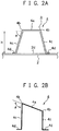
- the floor cross member 4 is a press-molded body composed of high tensile strength steel having a tensile strength of 440 MPa or larger, has a web surface 4a as the top surface, ridge parts 4b, 4b contiguous to web surface 4a, and vertical wall surfaces 4c, 4c contiguous to the ridge parts 4b, 4b, and has a ditch-like transverse cross-sectional shape tapered to give nearly a trapezoidal form.
- the floor cross member 4 also has flanges 4d, 4d which are contiguous to the vertical wall surfaces 4c, 4c and protrude sideward.
- the floor cross member 4 is joined through the flanges 4d, 4d to the top surface 2d of the front floor panel 2, typically by spot welding.
- the floor cross member 4 additionally has flanges 4e. As seen in FIG. 1B , the flanges 4e are formed at around both longitudinal ends of the floor cross member 4, continuously along the web surface 4a, the ridge parts 4b, 4b and vertical wall surfaces 4c, 4c. In other words, there is no notch 4f as seen in FIG. 1C , which has been indispensable for a conventional floor cross member 4' composed of high tensile strength steel having a tensile strength of 390 MPa or larger.
- the floor cross member 4 preferably has a tensile strength of 440 MPa or larger, and more preferably 590 MPa or larger. By the selection, the floor cross member 4 can be thinned, and the vehicle body can be reduced in weight.
- the floor cross member 4 preferably has a thickness of 1.0 to 2.0 mm for example, more preferably 1.6 mm or smaller, and furthermore preferably 1.4 mm or smaller.
- the transverse cross-sectional shape of the floor cross member 4 is not limited thereto, and may be a shape, as typically illustrated in FIG. 2B , with the web surface 4a inclined away from the horizontal line.
- the angle ⁇ formed between the web surface 4a and the vertical wall surface 4c is preferably 80° or larger and 100° or smaller.
- the flanges 4e can be formed by press forming, at both longitudinal ends of the floor cross member 4 composed of high tensile strength steel having a tensile strength of 440 MPa or larger.
- the ridge part 4b preferably has a radius of curvature of 8 mm or larger.
- the ridge part 4b preferably has a radius of curvature of 8 mm or larger is that, if the radius of curvature R of the ridge part 4b is smaller than 8 mm, the flange 4e may have crack or other defect at the edge thereof in the process of press forming. While the radius of curvature of the ridge part has generally been set to 3 to 5 mm or around, the flange would have a large strain at the edge thereof under the radius of curvature of 3 to 5 mm or around, so that there has been no other choice than providing the notch, rather than the flange, at around the ridge part.
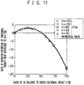
- FIG. 11 is a graph illustrating rate of increase/decrease of torsional rigidity, with reference to the torsional rigidity under a radius of curvature R of 0 mm, when measured for every ratio of 2R relative to the cross-sectional height H. If the condition of 0.12 ⁇ 2R/H ⁇ 0.50, or 0.06 ⁇ R/H ⁇ 0.25, is satisfied, the torsional rigidity can be increased above that expected from the shape with a radius of curvature R of 0 mm.
- the radius of curvature R of the ridge part 4b increases from the conventional one, thereby the stretch flanging during the press forming can be moderated to suppress the tensile strain possibly occurs at the edge of flange 4e. Accordingly, cracking is certainly prevented from occurring in the process of manufacturing, by press forming, of the floor cross member 4 having the flanges 4e formed on both longitudinal ends, and thereby the flanges 4e are formed in a more reliable manner at both longitudinal ends of the floor cross member 4.
- the reason why a range of 0.06 ⁇ R/H ⁇ 0.185 is preferred is that the torsional rigidity can be increased as compared with the conventional general floor cross member.
- the flanges 4e, 4e formed on the floor cross member 4 has, as illustrated in FIG. 1B , straight parts 4e-1, 4e-1 which extend along the web surface 4a and the vertical wall surface 4c, and a curved part 4e-2 which extends along the ridge part 4b.
- FIG. 3A and FIG. 3B are drawings illustrating the flange 4e and a joint part 20 of a conventional floor cross member 4' when viewed in the axial direction.
- FIG. 3C and FIG. 3D are drawings illustrating the flange 4e and the joint part 20 of a floor cross member 4 of an embodiment.
- a joint part (spot-welded part) 20 for connection with the vertical wall 2c or with the side sill inner panel 3a is designed to fall in the curved part 4e-2. While at least one joint part 20 falls in the curved part 20 as illustrated in FIG. 3C , the joint part 20 may alternatively fall, as illustrated in FIG. 3D , on the boundary between the straight part 4e-1 and the curved part 4e-2, so as to lie across both parts.
- the floor cross member 4 is joined with the front floor panel 2 or the side sill 3.
- the joint part 20 By such provision of the joint part 20 to the curved part 4e-2 of the flange 4e, the floor cross member 4 and the vertical wall 2c or the side sill inner panel 3a are tightly joined, and thereby the vehicle body 1 can be improved in the rigidity of the floor structure and the load transmission performance under impact load.
- the flange 4e has a flange width l fc at the center in the perimeter direction of the curved part 4e-2 thereof, which is not smaller than the minimum flange width l fs in the region excluding the center in the perimeter direction of the curved part 4e-2.
- the center in the perimeter direction of the curved part does not mean the exact half of center angle ⁇ (see FIG. 4 , for example) of the curved part 4e-2, but typically means an approximately ⁇ 5% range which ranges on both sides of the center (exact center) in the perimeter direction of the curved part 4e-2.
- the flange width l fc is defined to be the minimum width in a ⁇ 5% range on both sides of the center.
- Simplified geometry of the components may, however, degrade various performances including the above-described collision characteristic, and torsional rigidity and flexural rigidity of the vehicle body.
- the floor cross member 4' intended to be applied with high tensile strength steel, barely ensures a necessary level of formability at present by providing the notch 4f to the flanges 4e formed at the longitudinal ends, so as to give a geometry having no portion affected by stretch flanging. Since this sort of notch 4f is provided along the ridge part 4b, so that, if the radius of curvature R of the ridge part 4b is large, a region of the notch 4f inevitably increases as a consequence. For this reason, the radius of curvature R of the ridge part 4b of the floor cross member 4 at present is limited to a small value of 3 to 5 mm or around.
- the floor structure 1a of the vehicle body 1 is required to have a high level of shock absorbing performance for protecting the crew in case of side impact, similarly as required for the side sill 3 illustrated in FIG. 1A .
- the floor cross member 4 is a component for which shock absorbing performance in the initial stage of impact in an axial (in the direction of vehicle width) collapse mode.
- the floor cross member 4 disposed nearly at the longitudinal center of the vehicle body is also required to improve the torsional rigidity of the vehicle body.
- FIG. 4A and FIG. 4B are drawings illustrating the straight parts 4e-1, 4e-1 and the curved part 4e-2 of the flange 4e formed in the floor cross member 4.
- symbol Rp represents the start point and the end point of the curved part 4e-2
- symbol Rf represents a curve indicating position of rising of the flange 4e. Note that FIG. 4A illustrates a case where the straight parts 4e-1, 4e-1 and the curved part 4e-2 have the same flange width.
- the joint part is preferably provided in a region of the curved part 4e-2 which satisfies 1/4 to 3/4 of the center angle ⁇ (deg.) of the curved part 4e-2, and also satisfies 1/10 to 9/10 of the flange width fl (mm) (hatched area in FIG. 4A ).
- Methods of joining are exemplified by electric resistance welding such as spot welding, various types of laser welding, and bonding, wherein spot welding is preferable from the viewpoint of cost.
- FIG. 4B illustrates a case where the angle ⁇ between the web surface 4a and the vertical wall surface 4c is approximately 85°, with a fluctuating radius of curvature in the curved part 4e-2, and with a non-uniform flange width.
- the spot welding is given in an area of the flange 4e projected from the area bounded by these two normal lines 41, 42. While the predetermined angle was given as 10% of ⁇ , an effective point to be spot-welded can be determined even if the curved part 4e-2 is ambiguous, by determining the predetermined angle in a 10 ⁇ 2% range of ⁇ .
- FIG. 5A and FIG. 5B are drawings schematically illustrating methods of forming the floor cross member 4.
- the methods of forming the floor cross member 4 are selected from a method illustrated in FIG. 5A , based on deep drawing, trimming of excessive materials and raising the flange 4e; and a method illustrated in FIG. 5B , based on bending of a blank with a developed shape.
- any effort of obtaining the continuous flange 4e having the curved part 4e-2 and an appropriately large flange width will naturally produce cracks in the curved part 4e-2 due to stretch flanging and wrinkles at the base, failing to obtain a desired geometry.
- many of current general methods of forming select bending from the viewpoint of improving the material yield. In this case, cracking in the stretched flange part will be an issue to be solved.
- a blank having a developed shape of product is preferably used, since bending gives smaller material stretch than in drawing.
- FIG. 6A is a drawing for explaining a conventional blank shape
- FIG. 6B is a drawing for explaining a geometry of strain-distributed blank.
- a strain-distributed blank shape illustrated in FIG. 6B in which an excessive geometrical margin "a" is additionally provided to the developed blank shape of the floor cross member 4, specifically in a flange-corresponding area along a ridge part-corresponding area (area finally formed into the ridge part 4b).
- FIG. 7 is a graph illustrating an exemplary relation between position in the curved part 4e-2 of the flange 4e and strain.
- the abscissa of FIG. 7 represents position on the flange edge, and the ordinate represents rate of decrease of flange thickness.
- the deformation is suppressed from being localized, thereby a good result of formation can be obtained in the stretch-flanged part with a distributed deformation (distributed strain).
- the flange tends to be thinned locally in an area of the curved part 4e-2 corresponded to the center in the perimeter direction of the ridge part 4b (see the broken line in FIG. 7 ).
- the strain-distributed blank when used, the flange will not be maximally thinned in an area of the curved part 4e-2 corresponded to the center in the perimeter direction of the ridge part 4b (see the solid line in FIG. 7 ).
- the excessive geometrical margin "a” is preferably set to satisfy 0.03(R+fl) ⁇ a ⁇ 0.5(R+fl), where R represents the radius of curvature of the ridge part 4b, and fl represents the flange width of the straight part 4e-1 of the flange 4e as illustrated in FIG. 4B .
- the floor cross member 4 may alternatively be a cylindrical body formable, for example, by hydroforming (with a closed transverse cross-sectional shape).
- the flanges may be formed at both longitudinal ends of the floor cross member so as to surround the whole perimeter, or may be formed so as to be continuous only along the web surface, the ridge part contiguous to the web surface, and the vertical wall surface contiguous to the ridge part.
- a material model used herein was a cold-rolled steel sheet with a tensile strength of 590 MPa-class, and a thickness of 1.4 mm.
- FIG. 8A is a drawing schematically illustrating a simple shape model 5 (referred to as "analytical model 5", hereinafter) of the floor cross member 4.
- analytical model 5" hereinafter
- Axial collapse characteristics required for the floor cross member 4 were analyzed while representing it with the analytical model 5 illustrated in FIG. 8A .
- the flange 6 was formed to have a notch 7 in the curved part thereof for representing the conventional example ( FIG. 8C ), and also formed continuously around the whole perimeter without forming notch for representing the present invention ( FIG. 8B ), with a cross-sectional perimeter of the component as "s".
- the collision characteristic was evaluated in terms of energy absorption efficiency (EA/s) at a displacement by collision of 5 mm, induced by collision at an impact velocity of 15 km/h.
- EA/s energy absorption efficiency
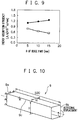
- FIG. 9 is a graph illustrating relation between energy absorption efficiency (collision characteristic) and the radius of curvature R of the ridge part 8 under 5-mm displacement by collision.
- plot ⁇ represents the present invention
- plot ⁇ represents the conventional example.
- the conventional example is reduced in the collision characteristic as the radius of curvature R of the ridge part 8 increases.
- the present invention increases in collision characteristic as the radius of curvature R of the ridge part 8 increases.
- FIG. 10 is a drawing schematically illustrating an analytical model 9 of the floor cross member 4.
- the torsional rigidity required for the floor cross member 4 was analyzed while representing it with the analytical model 9 illustrated in FIG. 10 .
- Table 1 summarizes analyzed combinations of cross-sectional height H and radius of curvature R. [Table 1] H (mm) R (mm) 30 0, 5, 10, 15(Circle) 50 0, 5, 15, 25(Circle) 80 0, 5, 10, 10, 15, 30, 40(Circle) 100 0, 3, 5, 12, 15, 30, 45, 50(Circle) 120 0, 3, 5, 10, 15, 30, 45, 60(Circle)
- the torsional rigidity was evaluated in terms of moment N ⁇ m per unit angle (deg.), that is N ⁇ m/deg, which generates in the analytical model 9.
- FIG. 11 is a graph illustrating analytical results of rate of increase/decrease of torsional rigidity, with reference to the torsional rigidity under a radius of curvature R of 0 mm, when studied for every ratio of 2R relative to the cross-sectional height H.
- FIG. 12 is a graph illustrating influences of the radius of curvature R of the ridge part 9c exerted on the torsional rigidity, when compared between presence and absence of notch.
- the analytical model 9 was assumed to have a flange formed continuously around the whole perimeter, although actually not provided with the flange.
- analytical model 9 was notched in the individual ridge parts 9c, to a depth of 5 mm from the longitudinal end, to represent a conventional example.
- the analytical model 9 was assumed to have notches in the curved parts, although actually not provided with the flange.
- plot o represents the present invention
- plot ⁇ represents the conventional example.
- the present invention attains the torsional rigidity larger than that of the conventional example with the notched flanges.
- FIG. 13 is a drawing schematically illustrating an analytical model 10 of the floor cross member 4.
- the individual flanges 11 were joined by spot welding to rigid walls 15, displacement of one rigid wall 15 was completely locked, and the other rigid wall 15 was applied with rotational displacement.
- FIG. 14 is a drawing illustrating layouts of the spot-welded points on the flange 11 at the end of the analytical model 10.
- Model A has the spot-welded parts at the center of the individual curved parts, and at the center of the individual straight parts of the flange 11, eight spots in total.
- Model B has the spot-welded parts at the boundaries between the individual curved parts and the straight parts of the flange 11, eight spots in total.
- Model C has the spot-welded parts at positions trisecting the individual straight parts of the flange 11, eight spots in total.
- Model D has the spot-welded parts at the center of the individual curved parts, and at positions trisecting the individual straight parts of the flange 11, twelve spots in total.
- Model E has the spot-welded parts at the boundaries between the individual curved parts and the straight parts, and at the center the individual straight parts of the flange 11, twelve spots in total.
- Model F has the spot-welded parts at the center of the individual curved parts, at the boundaries between the individual curved parts and the straight parts, and at the center of the individual straight parts of the flange 11, sixteen spots in total.
- Model G has the spot-welded parts at the boundaries between the individual curved parts and the straight parts, and at position trisecting the individual straight parts of the flange 11, sixteen spots in total.
- FIG. 15 is a graph illustrating relation between the number and position of spot-welded points, which affects the torsional rigidity.
- FIG. 16 is a drawing illustrating a square-cylindrical analytical model 12.
- the flange 14 was formed to have a notch 7 in the curved part thereof for representing a notched model (same as FIG. 8C ), and also formed continuously around the whole perimeter without forming notch for representing the present invention (same as FIG. 8B ).
- the analytical model 12 was joined through the flange 14 to the solid walls 15 by spot welding.
- the diameter of spot was 6 mm.
- the analytical model 12 was given mechanical characteristic values equivalent to those of 590 MPa-class general cold-rolled steel sheet having a thickness of 1.4 mm. Torsional load was applied, while fixing one solid wall 15, by giving rotational displacement to the other solid wall (not illustrated) around the axis of the analytical model 12.
- FIG. 17A is a drawing illustrating layouts of the spot-welded points on the flange 14 of the analytical model 12.
- FIG. 18 is a drawing illustrating layouts of the spot-welded points in model 2 and its modified models 7, 8, 9, 10 and 16.
- the spot-welded point was provided at the fixed center of each straight part of the flange 14, and also provided in the curved part while varying the central angle ⁇ " from 0° to 45° at 11.3° intervals.
- the spot-welded point in the curved part of the flange 14 falls on a position with a center angle ⁇ " of 45° in model 2, falls on a position with a center angle ⁇ " of 33.6° in model 7, falls on a position with a center angle ⁇ " of 22.5° in model 8, falls on a position with a center angle ⁇ " of 11.3° in model 9, and falls on a position with a center angle ⁇ " of 0° in model 10.
- model 16 it falls on a position in the straight part of the flange (a point 25 mm away from the center of the curved part).
- FIG. 19 is a drawing illustrating layouts of the spot-welded points in model 2 and its modified models 11 and 12.
- the position of spot welding in the curved part of the flange 14 falls on the widthwise center position of the flange 14 in model 2, falls on a position closest to the edge of the flange 14 in model 11, and falls on a position closest to the curve indicating position of rising of the flange 14 in model 12.
- the torsional rigidity was evaluated in terms of torsional rigidity per unit angle of torsion (N ⁇ m/deg.), before the individual models cause plastic deformation.
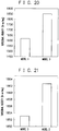
- FIG. 20 is a graph illustrating torsional rigidity of models 1 to 3.
- FIG. 21 is a graph illustrating torsional rigidity of models 3 and 2.
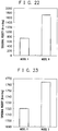
- FIG. 22 is a graph illustrating torsional rigidity of models 4 and 6.
- FIG. 23 is a graph illustrating torsional rigidity of models 6 and 5.
- FIG. 24 is a graph collectively illustrating torsional rigidity of models 2, 3, 7, 8, 9, 10 and 3.
- FIG. 25 is a graph collectively illustrating absorbed energy of models 2, 3, 7, 8, 9, 10 and 3.
- FIG. 26 is a graph illustrating torsional rigidity of models 2, 11 and 12.
- FIG. 27 is a graph illustrating absorbed energy of models 2, 11 and 12.
- FIG. 28 is a drawing illustrating layouts of the spot-welded points in models 13 to 15.
- each spot-welded point was disposed the same distance away from the axis of rotation.
- FIG. 29 is a graph illustrating the torsional rigidity of models 13 to 15.
- model 13 having the spot-welded point disposed in the curved part of the flange showed the highest torsional rigidity, showing a significant difference.
- FIG. 30 is a drawing illustrating layouts of the spot-welded points in models 16 and 17.
- FIG. 31 is a graph illustrating the torsional rigidity of models 16 and 17, and FIG. 32 is a graph illustrating the absorbed energy of models 16 and 17.
- the torsional rigidity and the collision characteristic are improved by providing the flange around the whole perimeter of the longitudinal end, and by providing a single spot-welded part in each curved part of the flange, and that the torsional rigidity and the collision characteristic are further improved by forming two spot-welded parts in the curved portion of the flange.
- the present invention is applicable to a vehicle body composed of longitudinal members such as side sill, roof rail, front floor having floor tunnel part, and side members, which are disposed as aligned in the front-back direction of the vehicle body; and widthwise members such as floor cross member and roof cross member, which are disposed as aligned in the widthwise direction of the vehicle body.
Landscapes
- Engineering & Computer Science (AREA)
- Chemical & Material Sciences (AREA)
- Combustion & Propulsion (AREA)
- Transportation (AREA)
- Mechanical Engineering (AREA)
- Body Structure For Vehicles (AREA)
Abstract
Description
- The present invention relates to a vehicle body which has a longitudinal member disposed as aligned in the front-back direction of the vehicle body, and a widthwise member disposed as aligned in the widthwise direction of the vehicle body.
- Vehicle body composed of a unit construction body (monocoque body) is configured by using, as main skeletal components, long longitudinal members such as side sill, roof rail, front floor having floor tunnel part, and side member, which are disposed as aligned in the front-back direction of the vehicle body; and long widthwise members such as floor cross member and roof cross member, which are disposed as aligned in the widthwise direction of the vehicle body. The longitudinal member and the widthwise member are generally joined with each other through flanges formed at the longitudinal (axial) ends of the widthwise member, in order to ensure rigidity of the vehicle body and to bear the load.
- The widthwise member is applied with load in the axial direction thereof induced by deformation of the cross-sectional shape of the longitudinal member, and also with torsional moment induced by displacement of the longitudinal member. The widthwise member is, therefore, required to suppress deformation possibly caused by the load applied in the axial direction, and to have a high torsional rigidity which affects driving stability of vehicles.
- To minimize the amount of deformation of the widthwise member, it is necessary to effectively apply the axial load to the cross section of the widthwise member, and to optimize the cross-sectional shape and joining conditions of the widthwise member.
- Also for the purpose of elevating the torsional rigidity of the widthwise member, it is again necessary to optimize the cross-sectional shape and joining conditions of the widthwise member, similarly as described above.
- For the purpose of suppressing deformation of the widthwise member under axial load, it is preferable to ensure a large cross-sectional area of the widthwise member, and to join the widthwise members with the longitudinal member at points in the flange as close as possible to the cross-sectional profile. On the other hand, for the purpose of enhancing the torsional rigidity of the widthwise member, it is again preferable to ensure a large cross-sectional area of the widthwise member. However, in contrast to the above-described conditions for suppressing deformation, it is preferable to join the widthwise member with the longitudinal member, at points in the flange as apart as possible from the cross-sectional profile. In short, while ensuring a large cross-sectional area of the widthwise member, the geometry of flange of the widthwise member and the points of joining are necessarily optimized, taking suppression of deformation and improvement in the torsional rigidity of the widthwise member into consideration.
- Now the flange, which is formed at the longitudinal end of the widthwise member and serves as a joint part between the widthwise member and the longitudinal member, is molded by press molding as a result of extensional deformation. Accordingly, all efforts of forming the flange along the ridge part of the widthwise member will inevitably result in concentration of the extensional deformation locally at the edge of the flange. As a consequence, in the process of press forming, the flange would sometimes rupture at the edge thereof, when intended to be long enough in width.
- It has therefore been a conventional practice to provide a notch at around the ridge part of the widthwise member, rather than providing the flange. Alternatively, even if the flange is formed along the ridge part of the widthwise member, the flange has been minimized in width in a portion thereof corresponded to the center in the perimeter direction of the ridge part. As a consequence, the widthwise member has no joining point, typically by spot welding, in the flange thereof especially in a portion corresponded to the ridge part. This has been one of the causes of inhibiting suppression of deformation and improvement in torsional rigidity of the widthwise member.
- A specific explanation will be given below, referring to the case where the longitudinal member is configured by the side sills and the tunnel part of a front floor panel, and the the widthwise member is configured by the floor cross member. The floor of the vehicle body (simply referred to as "floor", hereinafter) not only primarily takes part in ensuring necessary levels of torsional rigidity and flexural rigidity of the vehicle body during driving, but also takes part in transmission of impact load in case of car crash, and largely affects the weight of vehicle body. The floor is therefore required to satisfy contradictory requirements regarding high rigidity and light weight. A general structure employed by the floor is such as having the front floor panel; and a floor cross member which is joined to the top surface (the surface faced to the cabin) of the front floor panel, and connects the tunnel part which is formed so as to bulge at around the widthwise center of the front floor panel, and side sill inner panels which are spot-welded to both widthwise edges of the front floor panel. By spot-welding the floor cross member to the front floor panel, the tunnel part, and to the side sill inner panels, the floor structure will be improved in rigidity, and in load transmission performance under impact load.
- In the conventional process of spot welding of the floor cross member respectively to the top surface of the front floor panel, the outer surfaces of the side sill inner panels, and to the vertical wall surface of the tunnel part of the front floor panel, it was general to use an outward flange formed, as a welding margin, at both longitudinal ends of the floor cross member.
- The floor cross member is a structural component which takes part in improving the rigidity of vehicle body and in absorbing impact load in case of side impact. In recent years, from the viewpoints of weight reduction and improvement in collision safety, a thinner and more strong high tensile strength steel, for example a high tensile strength steel (HTSS) having a tensile strength of 390 MPa or larger, is used as a material for the floor cross member.
- The high tensile strength steel has, however, suffered from a low design freedom of the floor cross member, due to its poor formability.
- More specifically, for the case where the floor cross member is composed of a high tensile strength steel of 390 MPa or higher, the flange, which is formed at the end of the floor cross member to be serve as the joint part with the side sill inner panels or with the tunnel part, will be affected by a severe stretch flanging at the edge of the curved part, and may rupture in the process of press forming due to poor formability of the floor cross member. The floor cross member, therefore, had to be compensated for the shortage of the formability typically by provision of a notch, rather than provision of the flange, at around the ridge part, while resigning itself to degradation in the torsional rigidity and load transmission performance. The notch has, however, been concerned about degradation of various performances of the floor cross member, including collision characteristic regarding axial collapse, and torsional rigidity.
- Regarding this sort of technology,
Patent Literature 1 discloses a floor structure directed to suppress deformation of vehicle interior in case of collision, by providing a means for reducing impact deformation strength, such as a notch, at the end of the floor cross member. -
Patent Literature 2 discloses a floor structure in which the floor cross member is connected to a side sill, by connecting the floor cross member to a side sill reinforcement. -
Patent Literature 3 discloses a floor structure elevated in the rigidity by welding the floor cross member and the side sill, by spot-welding the upper part of a side sill inner panel and the flange of the floor cross member. -
Patent Literature 4 discloses a floor structure in which the floor cross member and the side sill are connected, by folding the edge of the side sill inner panel to be connected to the floor cross member. -
- [Patent Literature 1] Specification of Japanese Patent No.
3120635 - [Patent Literature 2] Specification of Japanese Patent No.
2996031 - [Patent Literature 3] Specification of Japanese Patent No.
3125476 - [Patent Literature 4] Japanese Laid-open Patent Publication No.
02-141372 - The floor structure disclosed in
Patent Literature 1 has a risk of excessive intrusion, into the cabin, of a deformed part caused by the means for reducing impact deformation, if the impact load is large. - The floor structure disclosed in
Patent Literature 2 has a fear of complicating the geometry of the side sill inner panel and the floor cross member, and of inducing crack or degradation of dimensional accuracy in the process of press forming originated from a blank plate. - The floor structure disclosed in
Patent Literature 3 may not only complicate the geometry of the side sill inner panel and the floor cross member, but may even disable the vehicle body from being assembled in some kinds of process of assembling by spot welding, possibly needing a vast change in assembly process of vehicle body. - The floor structure disclosed in
Patent Literature 4 inevitably increases the manufacturing cost, due to complicated process of forming of the side sill inner panel. - In addition, although not clearly stated, the floor cross members in the floor structures disclosed in
Patent Literatures 1 to 4, filed in 1988 to 1994, are products of the era wherein the high tensile strength steel was not so popularly used. From this point of view, all products are considered to be made of common steel sheet having a tensile strength of 300 to 340 MPa or around, rather than the high tensile strength steel. Accordingly, even with these inventions, there will be no other choice than providing the flanges at around the ridge part, at both longitudinal ends of the floor cross member made of a high tensile strength steel having a tensile strength of 390 MPa or larger. - It is therefore an object of the present invention to provide a vehicle body which has a longitudinal member, and a widthwise member joined through a flange formed at the axial end thereof to the longitudinal member, which is suppressed in deformation of the widthwise member, and is improved in the torsional rigidity.
- More specifically, the present invention is directed to provide a vehicle body having, for example, a front floor panel, and a floor cross member which is joined to the top surface of the front floor panel, and connects the tunnel part of the front floor panel and the side sill joined to the front floor panel, having all characteristics of high rigidity, good load transmission performance, and lightness of weight.
- The present invention is enumerated below.
- [1] A vehicle body which includes a longitudinal member disposed as aligned in the front-back direction of the vehicle body, and a widthwise member disposed as aligned in the widthwise direction of the vehicle body,
the widthwise member having at least a web surface which configures the top surface, a ridge part contiguous to the web surface, and a vertical wall surface contiguous to the ridge part,
the widthwise member having a flange formed at the longitudinal end continuously around at least the web surface, the ridge part and the vertical wall surface, and being connected through the flange to the longitudinal member,
the flange having a flange width lfc, at the center in the perimeter direction of the curved part thereof, being not smaller than the minimum flange width lfs in the region excluding the center in the perimeter direction of the curved part, and
the widthwise member having a tensile strength of 440 MPa or larger. - [2] The vehicle body of [1], wherein the widthwise member is a press-molded body having a ditch-like transverse cross-sectional shape.
- [3] The vehicle body of [1], wherein the ridge part has a radius of curvature R of 8 mm or larger, and the radius of curvature R (mm) and the height H (mm) of the transverse cross-sectional shape of the widthwise member satisfy the relational expression (1) below:

- [4] The vehicle body of [1], wherein the flange width lfc at the center in the perimeter direction of the curved part, and the minimum flange width lfs in the region excluding the center in the perimeter direction of the curved part, satisfy the relational expression (2) below:

- [5] The vehicle body of [1], wherein the angle formed between the web surface and the vertical wall surface is 80° or larger and 100° or smaller.
- [6] The vehicle body of [1], wherein the curved part has a joint part to be joined with the longitudinal member.
- [7] The vehicle body of [6], wherein the joint part falls in a range projected on the flange, the range being determined, when viewed in a transverse cross-section of the widthwise member at around the flange, by a normal line inclined by a predetermined angle away from the normal line on the web surface at around the boundary between the web surface and the ridge part, and by a normal line inclined by a predetermined angle away from the normal line on the vertical wall surface at around the boundary between the vertical wall surface and the ridge part.
- [8] The vehicle body of [6], wherein the joint part is a spot-welded part.
- [9] The vehicle body of [1], wherein the flange does not have a minimum thickness in a portion of the curved part, which is corresponded to the center in the perimeter direction of the ridge part.
- [10] A vehicle body which includes:
- a front floor panel which has a tunnel part with a vertical wall, nearly at the center of the widthwise direction, and has flange parts at both widthwise edges;
- a side sill joined through the flange part to the front floor panel; and
- a floor cross member which has at least a web surface which configures the top surface, a ridge part contiguous to the web surface, and a vertical wall surface contiguous to the ridge part, and is joined to the top surface of the front floor panel,
- the floor cross member having the flanges formed at both longitudinal ends continuously around at least the web surface, the ridge part and the vertical wall surface, and being connected through the flanges to the vertical wall and to the side sill,
- the flange having a flange width lfc, at the center in the perimeter direction of the curved part thereof, being not smaller than the minimum flange width lfs in the region excluding the center in the perimeter direction of the curved part, and
- the floor cross member having a tensile strength of 440 MPa or larger.
- [11] The vehicle body of [10], wherein the floor cross member is a press-molded body having a ditch-like transverse cross-sectional shape.
- [12] The vehicle body of [10], wherein the ridge part has a radius of curvature R of 8 mm or larger, and the radius of curvature R (mm) and the height H (mm) of the transverse cross-sectional shape of the floor cross member satisfy the relational expression (1) below:

- [13] The vehicle body of [10], wherein the flange width lfc at the center in the perimeter direction of the curved part, and the minimum flange width lfs in the region excluding the center in the perimeter direction of the curved part, satisfy the relational expression (2) below:

- [14] The vehicle body of [10], wherein the angle formed between the web surface and the vertical wall surface is 80° or larger and 100° or smaller.
- [15] The vehicle body of [10], wherein the curved part has a joint part to be joined with the vertical wall or the side sill.
- [16] The vehicle body of [15], wherein the joint part falls in a range projected on the flange, the range being determined, when viewed in a transverse cross-section of the floor cross member at around the flange, by a normal line inclined by a predetermined angle away from the normal line on the web surface at around the boundary between the web surface and the ridge part, and by a normal line inclined by a predetermined angle away from the normal line on the vertical wall surface at around the boundary between the vertical wall surface and the ridge part.
- [17] The vehicle body of [15], wherein the joint part is a spot-welded part.
- [18] The vehicle body of [10], wherein the flange does not have a minimum thickness in a portion of the curved part, which is corresponded to the center in the perimeter direction of the ridge part.
- According to the present invention, successfully provided is a vehicle body which has a longitudinal member, and a widthwise member joined through a flange formed at the axial end thereof to the longitudinal member, which is suppressed in deformation of the widthwise member, and is improved in the torsional rigidity.
- According to the present invention, also successfully provided is a vehicle body having, for example, a front floor panel, and a floor cross member which is joined to the top surface of the front floor panel, and connects the tunnel part of the front floor panel and the side sill joined to the front floor panel, being optimized in the geometry of the floor cross member, form and condition of joining between the floor cross member and the side sill or the tunnel part, and thereby having all characteristics of high rigidity, good load transmission performance, and lightness of weight.
-
- [
FIG. 1A] FIG. 1A is a perspective view partially illustrating a floor structure of a vehicle body according to an embodiment. - [
FIG. 1B] FIG. 1B is a drawing partially illustrating a flange part of a floor cross member of an embodiment. - [
FIG. 1C] FIG. 1C is a drawing partially illustrating a flange part of a conventional floor cross member. - [
FIG. 2A] FIG. 2A is a cross-sectional view taken along line II-II inFIG. 1A . - [
FIG. 2B] FIG. 2B is a transverse cross-sectional view schematically illustrating an exemplary floor cross member. - [
FIG. 3A] FIG. 3A is a drawing illustrating a flange and spot-welded parts of a conventional floor cross member. - [
FIG. 3B] FIG. 3B is a drawing illustrating a flange and joint parts of a conventional floor cross member. - [
FIG. 3C] FIG. 3C is a drawing illustrating a flange and joint parts of a floor cross member of an embodiment. - [
FIG. 3D] FIG. 3D is a drawing illustrating a flange and spot-welded parts of a floor cross member of an embodiment - [
FIG. 4A] FIG. 4A is a drawing illustrating straight parts and a curved part of a flange formed in the floor cross member. - [
FIG. 4B] FIG. 4B is a drawing illustrating straight parts and a curved part of a flange formed in the floor cross member. - [
FIG. 5A] FIG. 5A is a drawing schematically illustrating a method of forming a floor cross member. - [
FIG. 5B] FIG. 5B is a drawing schematically illustrating a method of forming a floor cross member. - [
FIG. 6A] FIG. 6A is a drawing for explaining a conventional blank shape. - [
FIG. 6B] FIG. 6B is a drawing for explaining a strain-distributed blank shape. - [
FIG. 7] FIG. 7 is a graph illustrating an exemplary relation between position in the curved part of the flange and strain. - [
FIG. 8A] FIG. 8A is a drawing schematically illustrating an analytical model of the floor cross member. - [
FIG. 8B] FIG. 8B is a drawing partially illustrating a flange part of the analytical model. - [
FIG. 8C] FIG. 8C is a drawing partially illustrating a flange part of the analytical model. - [
FIG. 9] FIG. 9 is a graph illustrating relation between energy absorption efficiency under a collision displacement of 5 mm (collision characteristic) and the radius of curvature R of the ridge part. - [
FIG. 10] FIG. 10 is a drawing schematically illustrating an analytical model of the floor cross member. - [
FIG. 11] FIG. 11 is a graph illustrating rate of increase/decrease of torsional rigidity, with reference to the torsional rigidity under a radius of curvature R of 0 mm, when measured for every ratio of 2R relative to the cross-sectional height H. - [
FIG. 12] FIG. 12 is a graph illustrating influences of the radius of curvature R of the ridge part exerted on the torsional rigidity, as compared between presence and absence of a notch. - [
FIG. 13] FIG. 13 is a drawing schematically illustrating an analytical model of the floor cross member. - [
FIG. 14] FIG. 14 is a drawing illustrating layouts of the spot-welded points in model A to model G. - [
FIG. 15] FIG. 15 is a graph illustrating relation between the torsional rigidity, and the number and position of spot-welded points affecting thereon. - [
FIG. 16] FIG. 16 is a drawing schematically illustrating an analytical model of the floor cross member. - [
FIG. 17A] FIG. 17A is a drawing illustrating layouts of the spot-welded points inmodel 1 tomodel 6. - [
FIG. 17B] FIG. 17B is a drawing illustrating layouts of the spot-welded points inmodel 1 tomodel 3. - [
FIG. 18] FIG. 18 is a drawing illustrating layouts of the spot-welded points inmodels - [
FIG. 19] FIG. 19 is a drawing illustrating layouts of the spot-welded points inmodels - [
FIG. 20] FIG. 20 is a graph illustrating the torsional rigidity ofmodels - [
FIG. 21] FIG. 21 is a graph illustrating torsional rigidity ofmodels - [
FIG. 22] FIG. 22 is a graph illustrating torsional rigidity ofmodels - [
FIG. 23] FIG. 23 is a graph illustrating torsional rigidity ofmodels - [
FIG. 24] FIG. 24 is a graph collectively illustrating the torsional rigidity ofmodels - [
FIG. 25] FIG. 25 is a graph collectively illustrating absorbed energy ofmodels - [
FIG. 26] FIG. 26 is a graph illustrating torsional rigidity ofmodels - [
FIG. 27] FIG. 27 is a graph illustrating absorbed energy ofmodels - [
FIG. 28] FIG. 28 is a drawing illustrating layouts of the spot-welded points inmodels 13 to 15. - [
FIG. 29] FIG. 29 is a graph illustrating torsional rigidity ofmodels 13 to 15. - [
FIG. 30] FIG. 30 is a drawing illustrating layouts of the spot-welded points inmodels - [
FIG. 31] FIG. 31 is a graph illustrating torsional rigidity ofmodels - [
FIG. 32] FIG. 32 is a graph illustrating absorbed energy ofmodels - An embodiment for carrying out the present invention will be explained below, referring to the attached drawings. This embodiment exemplifies a case where the longitudinal member is configured by the side sill and the tunnel part of the front floor panel, and the widthwise member is configured by the floor cross member. Note, however, that the present invention is not limited thereto, and is also applicable to a case where, for example, the longitudinal member is configured by a roof rail, and the widthwise member is configured by a roof cross member.
-
FIG. 1A is a perspective view partially illustrating a floor structure 1a of avehicle body 1 according to this embodiment. As seen inFIG. 1A , the floor structure 1a of thevehicle body 1 has afront floor panel 2, aside sill 3 as the longitudinal member, and afloor cross member 4 as the widthwise member. - The
front floor panel 2 has atunnel part 2a as the longitudinal member, and aflange part 2b. Thetunnel part 2a has a vertical wall 2c, and is formed at around the center, in the widthwise direction of vehicle body, of thefront floor panel 2, so as to bulge to give a ditch-like transverse cross-sectional shape. Inside (below the bottom surface) thetunnel part 2a, a propeller shaft for transmitting engine output to the rear wheels, and various pipings are housed. Theflange part 2b is formed upright at each of both widthwise edges of thefront floor panel 2. - General levels of strength and thickness of the
front floor panel 2 will suffice. For example, the tensile strength is typically 300 MPa or around, and the thickness is typically 0.6 to 0.7 mm or around. - The
side sill 3 is a long cylindrical body configured by a side sillinner panel 3a and a side sillouter panel 3b. The side sillinner panel 3a and the side sillouter panel 3b are joined to each other typically by spot welding, using flanges respectively formed at the end parts of both components. - The side sill
inner panel 3a is joined on the outer surface thereof to theflange part 2b of thefront floor panel 2, typically by spot welding. - General levels of strength and thickness of the side sill
inner panel 3a and the side sillouter panel 3b will suffice. For example, the tensile strength is typically 440 to 980 MPa or around, and the thickness is typically 1.0 to 2.0 mm or around. -
FIG. 2A is a cross-sectional view taken along line II-II inFIG. 1A . As seen inFIG. 1A andFIG. 2A , thefloor cross member 4 is a press-molded body composed of high tensile strength steel having a tensile strength of 440 MPa or larger, has aweb surface 4a as the top surface,ridge parts web surface 4a, and vertical wall surfaces 4c, 4c contiguous to theridge parts floor cross member 4 also hasflanges - The
floor cross member 4 is joined through theflanges top surface 2d of thefront floor panel 2, typically by spot welding. - The
floor cross member 4 additionally hasflanges 4e. As seen inFIG. 1B , theflanges 4e are formed at around both longitudinal ends of thefloor cross member 4, continuously along theweb surface 4a, theridge parts notch 4f as seen inFIG. 1C , which has been indispensable for a conventional floor cross member 4' composed of high tensile strength steel having a tensile strength of 390 MPa or larger. - The
floor cross member 4 preferably has a tensile strength of 440 MPa or larger, and more preferably 590 MPa or larger. By the selection, thefloor cross member 4 can be thinned, and the vehicle body can be reduced in weight. Thefloor cross member 4 preferably has a thickness of 1.0 to 2.0 mm for example, more preferably 1.6 mm or smaller, and furthermore preferably 1.4 mm or smaller. - The transverse cross-sectional shape of the
floor cross member 4 is not limited thereto, and may be a shape, as typically illustrated inFIG. 2B , with theweb surface 4a inclined away from the horizontal line. - The angle θ formed between the
web surface 4a and thevertical wall surface 4c is preferably 80° or larger and 100° or smaller. - If the angle θ is smaller than 80°, the torsional rigidity and the collision characteristic will become relatively low. To set the angle formed between the
web surface 4a and thevertical wall surface 4c to 80° or larger is one of conditions for maximizing an effect of omission of notch, and for enabling the omission of notch. In this way, theflanges 4e can be formed by press forming, at both longitudinal ends of thefloor cross member 4 composed of high tensile strength steel having a tensile strength of 440 MPa or larger. - On the other hand, press forming of the
floor cross member 4 becomes difficult if the angle θ exceeds 100°. - The
ridge part 4b preferably has a radius of curvature of 8 mm or larger. The radius of curvature R (mm), and the height H (mm) of the ditch-like transverse cross-sectional shape, tapered to give a nearly trapezoidal form, preferably satisfy 0.06≤R/H≤0.25, and more preferably 0.06≤R/H≤0.185. - The reason why the
ridge part 4b preferably has a radius of curvature of 8 mm or larger is that, if the radius of curvature R of theridge part 4b is smaller than 8 mm, theflange 4e may have crack or other defect at the edge thereof in the process of press forming. While the radius of curvature of the ridge part has generally been set to 3 to 5 mm or around, the flange would have a large strain at the edge thereof under the radius of curvature of 3 to 5 mm or around, so that there has been no other choice than providing the notch, rather than the flange, at around the ridge part. - The reason why the condition of 0.06≤R/H≤0.25 is preferred can be explained based on the results illustrated in the graph of
FIG. 11. FIG. 11 is a graph illustrating rate of increase/decrease of torsional rigidity, with reference to the torsional rigidity under a radius of curvature R of 0 mm, when measured for every ratio of 2R relative to the cross-sectional height H. If the condition of 0.12≤2R/H≤0.50, or 0.06≤R/H≤0.25, is satisfied, the torsional rigidity can be increased above that expected from the shape with a radius of curvature R of 0 mm. - By satisfying the 0.06≤R/H≤0.25, the radius of curvature R of the
ridge part 4b increases from the conventional one, thereby the stretch flanging during the press forming can be moderated to suppress the tensile strain possibly occurs at the edge offlange 4e. Accordingly, cracking is certainly prevented from occurring in the process of manufacturing, by press forming, of thefloor cross member 4 having theflanges 4e formed on both longitudinal ends, and thereby theflanges 4e are formed in a more reliable manner at both longitudinal ends of thefloor cross member 4. - The reason why a range of 0.06≤R/H≤0.185 is preferred is that the torsional rigidity can be increased as compared with the conventional general floor cross member. The conventional general floor cross member has a radius of curvature R of the ridge part of 3 to 5 mm or around, and a cross-sectional height H of 100 mm or around. If the range 0.12≤2R/H≤0.37, or 0.06≤R/H≤0.185 is satisfied, the torsional rigidity can be increased as compared with that of a floor cross member typically having a radius of curvature R of 5 mm, and a cross-sectional height H of 100 mm (2R/H=10%).
- The
flanges floor cross member 4 has, as illustrated inFIG. 1B ,straight parts 4e-1, 4e-1 which extend along theweb surface 4a and thevertical wall surface 4c, and acurved part 4e-2 which extends along theridge part 4b. -
FIG. 3A and FIG. 3B are drawings illustrating theflange 4e and ajoint part 20 of a conventional floor cross member 4' when viewed in the axial direction. On the other hand,FIG. 3C and FIG. 3D are drawings illustrating theflange 4e and thejoint part 20 of afloor cross member 4 of an embodiment. - As seen in
FIG. 1B ,FIG. 3C and FIG. 3D , a joint part (spot-welded part) 20 for connection with the vertical wall 2c or with the side sillinner panel 3a is designed to fall in thecurved part 4e-2. While at least onejoint part 20 falls in thecurved part 20 as illustrated inFIG. 3C , thejoint part 20 may alternatively fall, as illustrated inFIG. 3D , on the boundary between thestraight part 4e-1 and thecurved part 4e-2, so as to lie across both parts. Through thejoint part 20, thefloor cross member 4 is joined with thefront floor panel 2 or theside sill 3. - By such provision of the
joint part 20 to thecurved part 4e-2 of theflange 4e, thefloor cross member 4 and the vertical wall 2c or the side sillinner panel 3a are tightly joined, and thereby thevehicle body 1 can be improved in the rigidity of the floor structure and the load transmission performance under impact load. - Moreover, as illustrated in
FIG. 3C and FIG. 3D , theflange 4e has a flange width lfc at the center in the perimeter direction of thecurved part 4e-2 thereof, which is not smaller than the minimum flange width lfs in the region excluding the center in the perimeter direction of thecurved part 4e-2. Note that, in this specification, "the center in the perimeter direction of the curved part" does not mean the exact half of center angle α (seeFIG. 4 , for example) of thecurved part 4e-2, but typically means an approximately α±5% range which ranges on both sides of the center (exact center) in the perimeter direction of thecurved part 4e-2. For example, the flange width lfc is defined to be the minimum width in a ±5% range on both sides of the center. - As described above, low ductility as compared with that of low-strength steel sheet and poor formability are problems of the the high tensile strength steel to be applied to automobile components. For application of the high tensile strength steel, it is therefore effective to simplify the geometry of the components, and especially to find a geometry having no portion affected by stretch flanging.
- Simplified geometry of the components may, however, degrade various performances including the above-described collision characteristic, and torsional rigidity and flexural rigidity of the vehicle body.
- As illustrated in
FIG. 1C andFIG. 3A , the floor cross member 4', intended to be applied with high tensile strength steel, barely ensures a necessary level of formability at present by providing thenotch 4f to theflanges 4e formed at the longitudinal ends, so as to give a geometry having no portion affected by stretch flanging. Since this sort ofnotch 4f is provided along theridge part 4b, so that, if the radius of curvature R of theridge part 4b is large, a region of thenotch 4f inevitably increases as a consequence. For this reason, the radius of curvature R of theridge part 4b of thefloor cross member 4 at present is limited to a small value of 3 to 5 mm or around. - Even for the case where, as illustrated in
FIG. 3B , theflange 4e remains along theridge part 4b, a necessary level of formability is barely ensured by limiting the flange width lfc at the center in the perimeter direction of thecurved part 4e-2 to the minimum width (i.e., lfc<lfs), so as to assume a geometry having no portion affected by stretch flanging. - The floor structure 1a of the
vehicle body 1 is required to have a high level of shock absorbing performance for protecting the crew in case of side impact, similarly as required for theside sill 3 illustrated inFIG. 1A . In particular, thefloor cross member 4 is a component for which shock absorbing performance in the initial stage of impact in an axial (in the direction of vehicle width) collapse mode. - If the torsional rigidity and flexural rigidity of the vehicle body are poor, the vehicle body will cause elastic deformation due to reaction force input from road surface to the driving vehicle, so that the road-gripping ability of tire will no longer meet the design goal, and driving stability of the vehicle will degrade. Accordingly, the
floor cross member 4 disposed nearly at the longitudinal center of the vehicle body is also required to improve the torsional rigidity of the vehicle body. -
FIG. 4A and FIG. 4B are drawings illustrating thestraight parts 4e-1, 4e-1 and thecurved part 4e-2 of theflange 4e formed in thefloor cross member 4. InFIG. 4A , symbol Rp represents the start point and the end point of thecurved part 4e-2, and symbol Rf represents a curve indicating position of rising of theflange 4e. Note thatFIG. 4A illustrates a case where thestraight parts 4e-1, 4e-1 and thecurved part 4e-2 have the same flange width. - As seen in
FIG. 4A , the joint part is preferably provided in a region of thecurved part 4e-2 which satisfies 1/4 to 3/4 of the center angle α (deg.) of thecurved part 4e-2, and also satisfies 1/10 to 9/10 of the flange width fl (mm) (hatched area inFIG. 4A ). - Methods of joining are exemplified by electric resistance welding such as spot welding, various types of laser welding, and bonding, wherein spot welding is preferable from the viewpoint of cost.
- If the
curved part 4e-2 is not clearly determined, a point to be spot-welded is determined as illustrated inFIG. 4B. FIG. 4B illustrates a case where the angle θ between theweb surface 4a and thevertical wall surface 4c is approximately 85°, with a fluctuating radius of curvature in thecurved part 4e-2, and with a non-uniform flange width. - The point to be spot-welded is determined as follows. In the transverse cross-section of the
floor cross member 4 in the vicinity of theflange 4e, at around the boundary between theweb surface 4a and theridge part 4b, anormal line 41, which inclines a predetermined angle (for example, an angle equal to 10% of θ (=8.5°)) away from the normal line on theweb surface 4a, is found. Similarly, at around the boundary between thevertical wall surface 4c and theridge part 4b, anormal line 42, which inclines a predetermined angle (for example, an angle equal to 10% of θ (=8.5°)) away from the normal line on thevertical wall surface 4c, is found. The spot welding is given in an area of theflange 4e projected from the area bounded by these twonormal lines curved part 4e-2 is ambiguous, by determining the predetermined angle in a 10±2% range of θ. - Next, a method of forming the
floor cross member 4 will be explained. -
FIG. 5A and FIG. 5B are drawings schematically illustrating methods of forming thefloor cross member 4. - The methods of forming the
floor cross member 4 are selected from a method illustrated inFIG. 5A , based on deep drawing, trimming of excessive materials and raising theflange 4e; and a method illustrated inFIG. 5B , based on bending of a blank with a developed shape. However, any effort of obtaining thecontinuous flange 4e having thecurved part 4e-2 and an appropriately large flange width will naturally produce cracks in thecurved part 4e-2 due to stretch flanging and wrinkles at the base, failing to obtain a desired geometry. Moreover, many of current general methods of forming select bending, from the viewpoint of improving the material yield. In this case, cracking in the stretched flange part will be an issue to be solved. - When bending is selected, a blank having a developed shape of product is preferably used, since bending gives smaller material stretch than in drawing.
-
FIG. 6A is a drawing for explaining a conventional blank shape, andFIG. 6B is a drawing for explaining a geometry of strain-distributed blank. - In order to form the
flange 4e having an appropriately large length around the whole perimeter of theridge part 4b, it is preferable to use a strain-distributed blank shape illustrated inFIG. 6B , in which an excessive geometrical margin "a" is additionally provided to the developed blank shape of thefloor cross member 4, specifically in a flange-corresponding area along a ridge part-corresponding area (area finally formed into theridge part 4b). By using the strain-distributed blank shape provided with the excessive geometrical margin "a", thecurved part 4e-2 can be prevented from being localized with stretch flanging. -
FIG. 7 is a graph illustrating an exemplary relation between position in thecurved part 4e-2 of theflange 4e and strain. The abscissa ofFIG. 7 represents position on the flange edge, and the ordinate represents rate of decrease of flange thickness. - As seen in
FIG. 7 , by using the strain-distributed blank shape(developed blank), the deformation is suppressed from being localized, thereby a good result of formation can be obtained in the stretch-flanged part with a distributed deformation (distributed strain). When the conventional blank is used, the flange tends to be thinned locally in an area of thecurved part 4e-2 corresponded to the center in the perimeter direction of theridge part 4b (see the broken line inFIG. 7 ). In contrast, when the strain-distributed blank is used, the flange will not be maximally thinned in an area of thecurved part 4e-2 corresponded to the center in the perimeter direction of theridge part 4b (see the solid line inFIG. 7 ). - The excessive geometrical margin "a" is preferably set to satisfy 0.03(R+fl)≤a≤0.5(R+fl), where R represents the radius of curvature of the
ridge part 4b, and fl represents the flange width of thestraight part 4e-1 of theflange 4e as illustrated inFIG. 4B . - By providing the excessive geometrical margin "a" of this range, rate of substantial stretch flanging at the flange edge, induced by compressive deformation at the base of rising of the flange, can be suppressed from increasing. This is because the compressive stress generates at the base, and thereby the center angle around which the ridge part is formed in the blank shape increases. In short, by providing the excessive geometrical margin "a", the substantial perimeter of the stretched flange part can be increased, and thereby the deformation can be prevented from being localized.
- While the embodiment described above dealt with the case where the
floor cross member 4 has the ditch-like transverse cross-sectional shape, it may alternatively be a cylindrical body formable, for example, by hydroforming (with a closed transverse cross-sectional shape). In this case, the flanges may be formed at both longitudinal ends of the floor cross member so as to surround the whole perimeter, or may be formed so as to be continuous only along the web surface, the ridge part contiguous to the web surface, and the vertical wall surface contiguous to the ridge part. - Next, results of various performance evaluations of the floor structure of vehicle body according to the present invention, analyzed by CAE (FEM Code: LS-DYNA ver. 971), will be explained. A material model used herein was a cold-rolled steel sheet with a tensile strength of 590 MPa-class, and a thickness of 1.4 mm.
-
FIG. 8A is a drawing schematically illustrating a simple shape model 5 (referred to as "analytical model 5", hereinafter) of thefloor cross member 4. Axial collapse characteristics required for thefloor cross member 4 were analyzed while representing it with theanalytical model 5 illustrated inFIG. 8A . - The
analytical model 5 has cross-sectional height H=80 mm, flange width fl=15 mm, rising of flange Rf=5 mm, full length=300 mm, radius of curvature of ridge part 8 R=5, 10, 15 mm, and has aflange 6 at one longitudinal end. Theflange 6 was formed to have anotch 7 in the curved part thereof for representing the conventional example (FIG. 8C ), and also formed continuously around the whole perimeter without forming notch for representing the present invention (FIG. 8B ), with a cross-sectional perimeter of the component as "s". - The collision characteristic was evaluated in terms of energy absorption efficiency (EA/s) at a displacement by collision of 5 mm, induced by collision at an impact velocity of 15 km/h.
-
FIG. 9 is a graph illustrating relation between energy absorption efficiency (collision characteristic) and the radius of curvature R of theridge part 8 under 5-mm displacement by collision. In the graph ofFIG. 9 , plot ● represents the present invention, and plot □ represents the conventional example. - As seen in
FIG. 9 , the conventional example is reduced in the collision characteristic as the radius of curvature R of theridge part 8 increases. In contrast, the present invention increases in collision characteristic as the radius of curvature R of theridge part 8 increases. - It is understood from the analytical results that, for the purpose of improving the collision characteristic, it is efficient to increase the radius of curvature R of the
ridge part 8, and not to provide the notch to theflange 6 formed at the longitudinal end. -
FIG. 10 is a drawing schematically illustrating ananalytical model 9 of thefloor cross member 4. The torsional rigidity required for thefloor cross member 4 was analyzed while representing it with theanalytical model 9 illustrated inFIG. 10 . - The
analytical model 9 has cross-sectional height H=30 to 120 mm, full length=500 mm, and radius of curvature ofridge part 9c R=0 to 60 mm. Table 1 summarizes analyzed combinations of cross-sectional height H and radius of curvature R.[Table 1] H (mm) R (mm) 30 0, 5, 10, 15(Circle) 50 0, 5, 15, 25(Circle) 80 0, 5, 10, 10, 15, 30, 40(Circle) 100 0, 3, 5, 12, 15, 30, 45, 50(Circle) 120 0, 3, 5, 10, 15, 30, 45, 60(Circle) - The displacement at one
end 9a of theanalytical model 9 was completely locked, and the theother end 9b was applied with rotational displacement. - The torsional rigidity was evaluated in terms of moment N·m per unit angle (deg.), that is N·m/deg, which generates in the
analytical model 9. -
FIG. 11 is a graph illustrating analytical results of rate of increase/decrease of torsional rigidity, with reference to the torsional rigidity under a radius of curvature R of 0 mm, when studied for every ratio of 2R relative to the cross-sectional height H. - It is understood from
FIG. 11 that the torsional rigidity is maximized when the radius of curvature R of theridge part 9c equals to 12.5% of H, irrespective of the cross-sectional height H. -
FIG. 12 is a graph illustrating influences of the radius of curvature R of theridge part 9c exerted on the torsional rigidity, when compared between presence and absence of notch. The analytical model 9 (cross-sectional height H=100 mm), same as shown inFIG. 10 , was used to represent the present invention. Theanalytical model 9 was assumed to have a flange formed continuously around the whole perimeter, although actually not provided with the flange. On the other hand,analytical model 9 was notched in theindividual ridge parts 9c, to a depth of 5 mm from the longitudinal end, to represent a conventional example. Theanalytical model 9 was assumed to have notches in the curved parts, although actually not provided with the flange. In the graph ofFIG. 12 , plot o represents the present invention, and plot ▲ represents the conventional example. - It is understood from
FIG. 12 that the present invention attains the torsional rigidity larger than that of the conventional example with the notched flanges. -
FIG. 13 is a drawing schematically illustrating ananalytical model 10 of thefloor cross member 4. - The
analytical model 10 has cross-sectional height H=80 mm, flange width fl=15 mm, full length=500 mm, radius of curvature of ridge part R=10 mm, and hasflanges 11 at both longitudinal ends formed continuously around the whole perimeter. Theindividual flanges 11 were joined by spot welding torigid walls 15, displacement of onerigid wall 15 was completely locked, and the otherrigid wall 15 was applied with rotational displacement. -
FIG. 14 is a drawing illustrating layouts of the spot-welded points on theflange 11 at the end of theanalytical model 10. - Model A has the spot-welded parts at the center of the individual curved parts, and at the center of the individual straight parts of the
flange 11, eight spots in total. - Model B has the spot-welded parts at the boundaries between the individual curved parts and the straight parts of the
flange 11, eight spots in total. - Model C has the spot-welded parts at positions trisecting the individual straight parts of the
flange 11, eight spots in total. - Model D has the spot-welded parts at the center of the individual curved parts, and at positions trisecting the individual straight parts of the
flange 11, twelve spots in total. - Model E has the spot-welded parts at the boundaries between the individual curved parts and the straight parts, and at the center the individual straight parts of the
flange 11, twelve spots in total. - Model F has the spot-welded parts at the center of the individual curved parts, at the boundaries between the individual curved parts and the straight parts, and at the center of the individual straight parts of the
flange 11, sixteen spots in total. - Model G has the spot-welded parts at the boundaries between the individual curved parts and the straight parts, and at position trisecting the individual straight parts of the
flange 11, sixteen spots in total. -
FIG. 15 is a graph illustrating relation between the number and position of spot-welded points, which affects the torsional rigidity. - It was found from
FIG. 15 that, when compared under the same number of spot-welded points, models A, D and F (plot ▲), having the spot-welded points in the curved parts of theflange 11 of theanalytical model 10, gave the highest torsional rigidity. In short, it was found that the torsional rigidity may be improved by providing the spot-welded parts for connection with the side sill inner panel or with the tunnel part of the front floor, in the curved parts of theflange 11. -
FIG. 16 is a drawing illustrating a square-cylindricalanalytical model 12. - The
analytical model 12 has radius of curvature of ridge part 13 R=10 mm, angle formed by curved part ofridge part 13 α=90°, cross-sectional height H=80 mm, flange width fl=20 mm, rising of flange Rf=5 mm, full length=500 mm, withflanges 14 provided at both longitudinal ends, similarly to theanalytical model 10 illustrated inFIG. 13 . Theflange 14 was formed to have anotch 7 in the curved part thereof for representing a notched model (same asFIG. 8C ), and also formed continuously around the whole perimeter without forming notch for representing the present invention (same asFIG. 8B ). - The
analytical model 12 was joined through theflange 14 to thesolid walls 15 by spot welding. The diameter of spot was 6 mm. Theanalytical model 12 was given mechanical characteristic values equivalent to those of 590 MPa-class general cold-rolled steel sheet having a thickness of 1.4 mm. Torsional load was applied, while fixing onesolid wall 15, by giving rotational displacement to the other solid wall (not illustrated) around the axis of theanalytical model 12. -
FIG. 17A is a drawing illustrating layouts of the spot-welded points on theflange 14 of theanalytical model 12. -
Model 1 has a notch in each curved part of theflange 14, and has the spot-welded points in the straight parts of theflange 14. -
Model 2 has no notch in the curved part of theflange 14, and has the spot-welded points at the center of the straight parts and the curved parts of theflange 14. -
Model 3 has no notch in the curved part of theflange 14, and has the spot-welded points in the straight parts of theflange 14. -
Model 4 has a notch in each curved part of theflange 14, and has the spot-welded points at the center of the straight parts of theflange 14. -
Model 5 has no notch in the curved part of theflange 14, and has the spot-welded point at the center of each curved part of theflange 14. -
Model 6 has no notch in the curved part of theflange 14, and has the spot-welded point at the center of the straight parts of theflange 14. - Using
models 1 to 6 illustrated inFIG. 17A , influences of the notch exerted on the torsional rigidity, and advantage of provision of the spot-welded points in the curved parts of theflange 14 were investigated. - In each of
models 1 to 3, as illustrated inFIG. 17B , the spot-welded points, eight in total, were equally distributed around the center axis of torsion. - On the other hand, in each of
models 4 to 6, four spot-welded points in total were used. -
FIG. 18 is a drawing illustrating layouts of the spot-welded points inmodel 2 and its modifiedmodels - In this study, regarding the layouts of the spot-welded points in the
flange 14, positions within such areas but possibly yielding better effects were investigated. As illustrated inFIG. 18 , the spot-welded point was provided at the fixed center of each straight part of theflange 14, and also provided in the curved part while varying the central angle α" from 0° to 45° at 11.3° intervals. - The spot-welded point in the curved part of the
flange 14 falls on a position with a center angle α" of 45° inmodel 2, falls on a position with a center angle α" of 33.6° inmodel 7, falls on a position with a center angle α" of 22.5° inmodel 8, falls on a position with a center angle α" of 11.3° inmodel 9, and falls on a position with a center angle α" of 0° inmodel 10. Inmodel 16, it falls on a position in the straight part of the flange (apoint 25 mm away from the center of the curved part). -
FIG. 19 is a drawing illustrating layouts of the spot-welded points inmodel 2 and its modifiedmodels - In this study, relation between the torsional rigidity and position of spot welding was investigated while shifting the spot-welded point in the radial direction of the curved part of the
flange 14. - The position of spot welding in the curved part of the
flange 14 falls on the widthwise center position of theflange 14 inmodel 2, falls on a position closest to the edge of theflange 14 inmodel 11, and falls on a position closest to the curve indicating position of rising of theflange 14 inmodel 12. - The torsional rigidity was evaluated in terms of torsional rigidity per unit angle of torsion (N·m/deg.), before the individual models cause plastic deformation.
-
FIG. 20 is a graph illustrating torsional rigidity ofmodels 1 to 3.FIG. 21 is a graph illustrating torsional rigidity ofmodels FIG. 22 is a graph illustrating torsional rigidity ofmodels FIG. 23 is a graph illustrating torsional rigidity ofmodels - It was understood from comparison between
FIGs. 20 and22 , that a high level of torsional rigidity can be obtained by forming the curved part of the flange without notching. - It was understood from comparison between
FIGs. 21 and23 , under the same number of spot-welded points, a high level of torsional rigidity can be obtained by disposing the spot-welded points in the curved part of the flange. If the spot-welded points are disposed outside the curved part of the flange, the torsional rigidity and the collision characteristic will degrade, failing in obtaining desired performances. -
FIG. 24 is a graph collectively illustrating torsional rigidity ofmodels FIG. 25 is a graph collectively illustrating absorbed energy ofmodels FIG. 26 is a graph illustrating torsional rigidity ofmodels FIG. 27 is a graph illustrating absorbed energy ofmodels - It is understood from graphs of
FIGs. 24 and 25 that, for the case where the spot-welded point is disposed in the curved part of the flange, higher levels of torsional rigidity and absorbed energy can be obtained by disposing the spot-welded point at around the center of the flange (a region ranging from 1/10 to 9/10 of the center angle (deg.) of the curved part). - It is understood from the graph of
FIG. 26 that, for the case where the spot-welded point is disposed in the curved part of the flange, higher levels of torsional rigidity and absorbed energy can be obtained by disposing the spot-welded point closer to the edge of the flange (a region ranging from 1/2 to 1 of the flange width (mm)). - It is understood from the graph of
FIG. 27 that, for the case where the spot-welded point is disposed in the curved part of the flange, higher levels of torsional rigidity and absorbed energy can be obtained by disposing the spot-welded point closer to the rounded rising point of the flange (a region ranging from 0 to 1/2 of the flange width (mm)). - In short, it is understood from the graphs of
FIGs. 26 and 27 that, for the purpose of balancing high torsional rigidity and large absorbed energy, it is effective to dispose the spot-welded point in a region ranging from 1/4 to 3/4 of the flange width. -
FIG. 28 is a drawing illustrating layouts of the spot-welded points inmodels 13 to 15. - As seen in
FIG. 28 , in all ofmodels 13 to 15, each spot-welded point was disposed the same distance away from the axis of rotation. -
FIG. 29 is a graph illustrating the torsional rigidity ofmodels 13 to 15. - As seen in
FIG. 29 ,model 13 having the spot-welded point disposed in the curved part of the flange showed the highest torsional rigidity, showing a significant difference. - Using a floor cross member having two spot-welded points formed in each curved part of the flange, influences of the positions of spot welding in the flange exerted on the torsional rigidity and absorbed energy were analyzed.
-
FIG. 30 is a drawing illustrating layouts of the spot-welded points inmodels -
FIG. 31 is a graph illustrating the torsional rigidity ofmodels FIG. 32 is a graph illustrating the absorbed energy ofmodels - It is understood from
FIG. 31 and FIG. 32 that the torsional rigidity and the collision characteristic are improved by providing the flange around the whole perimeter of the longitudinal end, and by providing a single spot-welded part in each curved part of the flange, and that the torsional rigidity and the collision characteristic are further improved by forming two spot-welded parts in the curved portion of the flange. - The present invention is applicable to a vehicle body composed of longitudinal members such as side sill, roof rail, front floor having floor tunnel part, and side members, which are disposed as aligned in the front-back direction of the vehicle body; and widthwise members such as floor cross member and roof cross member, which are disposed as aligned in the widthwise direction of the vehicle body.
Claims (7)
- A vehicle body (1) comprising a longitudinal member (3) disposed as aligned in the front-back direction of the vehicle body (1), and a widthwise member (4) disposed as aligned in the widthwise direction of the vehicle body (1),
the widthwise member (4) having at least a web surface (4a) which is configured as a top surface, a ridge part (4b) contiguous to the web surface (4a), and a vertical wall surface (4c) contiguous to the ridge part (4b),
the widthwise member (4) having a flange (4d; 4e) formed at a longitudinal end continuously around at least the web surface (4a), the ridge part (4b) and the vertical wall surface (4c), and being connected through the flange (4d ; 4e) to the longitudinal member (3),
the flange (4d) having a flange width lfc, at a center in a perimeter direction of a curved part (4e-2) thereof, being not smaller than a minimum flange width lfs in the region excluding the center in the perimeter direction of the curved part (4e-2),
the widthwise member (4) having a tensile strength of 440 MPa or larger, and
characterized in that
the curved part (4e-2) has a joint part (20) to be joined with the longitudinal member (3),
the joint part (20) falls in a range projected on the flange (4e), the range being defined as an inside area bound, when viewed in a transverse cross-section of the widthwise member (4) at around the flange (4e),
by a line (41) inclined toward the ridge part (4b) by a first angle and away from a normal line on the web surface (4a) at around a boundary between the web surface (4a) and the ridge part (4b), and
by a line (42) inclined toward the ridge part (4b) by a second angle away from a normal line on the vertical wall surface (4c) at around a boundary between the vertical wall surface (4c) and the ridge part (4b); and
wherein each of the first angle and the second angle is 10±2% of an angle θ between an extended line of the web surface (4a) and the vertical wall surface (4c). - The vehicle body (1) according to Claim 1, wherein the widthwise member (4) is a press-molded body having a ditch-like transverse cross-sectional shape.
- The vehicle body (1) according to Claim 1, wherein the angle formed between the web surface (4a) and the vertical wall surface (4c) is 80° or larger and 100° or smaller.
- The vehicle body (1) according to Claim 1, wherein the joint part (20) is a spot-welded part (20).
- The vehicle body (1) according to Claim 1, wherein the flange (4e) does not have a minimum thickness in a portion of the curved part (4e-2), which is corresponded to the center in the perimeter direction of the ridge part (4b).
- The vehicle body (1) according to Claim 1, further comprising:a front floor panel (2) which has a tunnel part (2a) with a vertical wall (2c), nearly at the center of the widthwise direction, and has flange parts (2b) at both widthwise edges;a side sill (3) joined through the flange part (2b) to the front floor panel (2); anda floor cross member (4) which is joined to the top surface (2d) of the front floor panel (2),wherein the tunnel part (2a) and the side sill (3) constitute the longitudinal member, the floor cross member (4) constitutes the widthwise member, andwherein the floor cross member (4) has the flanges (4d; 4e) formed at both longitudinal ends and is connected through the flanges (4d; 4e) to the vertical wall (2c) and to the side sill (3).
- The vehicle body (1) according to Claim 1, wherein the widthwise member (4) is joined, alone by itself, to the longitudinal member (3), at the end having the flange (4d; 4e) formed thereon.
Applications Claiming Priority (3)
| Application Number | Priority Date | Filing Date | Title |
|---|---|---|---|
| JP2012088943 | 2012-04-10 | ||
| EP13775046.9A EP2837548B1 (en) | 2012-04-10 | 2013-04-09 | Vehicle body |
| PCT/JP2013/060756 WO2013154114A1 (en) | 2012-04-10 | 2013-04-09 | Vehicle body |
Related Parent Applications (2)
| Application Number | Title | Priority Date | Filing Date |
|---|---|---|---|
| EP13775046.9A Division EP2837548B1 (en) | 2012-04-10 | 2013-04-09 | Vehicle body |
| EP13775046.9A Division-Into EP2837548B1 (en) | 2012-04-10 | 2013-04-09 | Vehicle body |
Publications (2)
| Publication Number | Publication Date |
|---|---|
| EP3357795A1 true EP3357795A1 (en) | 2018-08-08 |
| EP3357795B1 EP3357795B1 (en) | 2019-07-17 |
Family
ID=49327676
Family Applications (2)
| Application Number | Title | Priority Date | Filing Date |
|---|---|---|---|
| EP13775046.9A Active EP2837548B1 (en) | 2012-04-10 | 2013-04-09 | Vehicle body |
| EP18153684.8A Active EP3357795B1 (en) | 2012-04-10 | 2013-04-09 | Vehicle body |
Family Applications Before (1)
| Application Number | Title | Priority Date | Filing Date |
|---|---|---|---|
| EP13775046.9A Active EP2837548B1 (en) | 2012-04-10 | 2013-04-09 | Vehicle body |
Country Status (12)
| Country | Link |
|---|---|
| US (1) | US9199670B2 (en) |
| EP (2) | EP2837548B1 (en) |
| JP (1) | JP5598632B2 (en) |
| KR (1) | KR101537202B1 (en) |
| CN (1) | CN104245482B (en) |
| CA (1) | CA2867108C (en) |
| ES (2) | ES2747904T3 (en) |
| IN (1) | IN2014DN07520A (en) |
| MX (1) | MX352297B (en) |
| MY (1) | MY168059A (en) |
| RU (1) | RU2581634C1 (en) |
| WO (1) | WO2013154114A1 (en) |
Families Citing this family (20)
| Publication number | Priority date | Publication date | Assignee | Title |
|---|---|---|---|---|
| KR101657680B1 (en) | 2013-09-30 | 2016-09-19 | 주식회사 엘지화학 | Polyolefin |
| WO2015053125A1 (en) * | 2013-10-09 | 2015-04-16 | 新日鐵住金株式会社 | Structural member for automobile body |
| CA2920881C (en) * | 2013-10-09 | 2018-03-20 | Nippon Steel & Sumitomo Metal Corporation | Method for manufacturing press-formed product and press-forming apparatus |
| KR101821909B1 (en) * | 2013-10-09 | 2018-01-24 | 신닛테츠스미킨 카부시키카이샤 | Method for manufacturing structural member for automobile body, and press molding device |
| CN106061824B (en) * | 2014-03-05 | 2018-03-13 | 新日铁住金株式会社 | The junction structure of component |
| KR20170010831A (en) * | 2014-06-30 | 2017-02-01 | 신닛테츠스미킨 카부시키카이샤 | Door impact beam |
| JP6162677B2 (en) * | 2014-11-28 | 2017-07-12 | 豊田鉄工株式会社 | Hot stamp trim parts |
| EP3219589B1 (en) * | 2014-12-22 | 2020-09-16 | Nippon Steel Corporation | Structural member |
| JP6354729B2 (en) * | 2015-10-22 | 2018-07-11 | トヨタ自動車株式会社 | Vehicle floor structure |
| MX2018015402A (en) * | 2016-06-16 | 2019-04-22 | Nippon Steel & Sumitomo Metal Corp | Drawn body for automobile structural member, method for manufacturing drawn body for automobile structural member, and apparatus for manufacturing drawn body for automobile structural member. |
| WO2018034104A1 (en) * | 2016-08-18 | 2018-02-22 | 新日鐵住金株式会社 | Automobile-body press-formed component and manufacturing method therefor |
| JP2018095160A (en) * | 2016-12-15 | 2018-06-21 | トヨタ自動車株式会社 | Vehicle lower structure |
| JP6538103B2 (en) * | 2017-04-25 | 2019-07-03 | 本田技研工業株式会社 | Body floor structure |
| JP6973499B2 (en) * | 2017-11-01 | 2021-12-01 | 日本製鉄株式会社 | Laminated joint structure |
| KR102153189B1 (en) | 2018-11-30 | 2020-09-07 | 주식회사 포스코 | Forming method for structure for reinforcement and structure for reinforcement |
| JP6665958B1 (en) * | 2019-03-19 | 2020-03-13 | Jfeスチール株式会社 | Joint structure of vehicle body frame parts, vehicle body frame parts, and method of manufacturing the vehicle body frame parts |
| DE102019120607A1 (en) * | 2019-07-31 | 2021-02-04 | Bayerische Motoren Werke Aktiengesellschaft | Motor vehicle |
| EP4011518A4 (en) | 2019-08-05 | 2022-09-28 | Nippon Steel Corporation | METHOD FOR MAKING A PRESS-FORMED PRODUCT, PRESS-FORMED PRODUCT AND PRESS-FORMED DEVICE |
| JP2021094941A (en) * | 2019-12-13 | 2021-06-24 | 本田技研工業株式会社 | Floor structure |
| WO2026029065A1 (en) * | 2024-07-30 | 2026-02-05 | 日本製鉄株式会社 | Automobile frame member |
Citations (9)
| Publication number | Priority date | Publication date | Assignee | Title |
|---|---|---|---|---|
| JPH02141372A (en) | 1988-11-22 | 1990-05-30 | Suzuki Motor Co Ltd | Car body structure for automobile |
| DE19711273A1 (en) * | 1996-03-19 | 1997-11-06 | Toyota Motor Co Ltd | Body chassis construction of motor vehicle |
| JP2996031B2 (en) | 1992-12-03 | 1999-12-27 | トヨタ自動車株式会社 | Car body structure |
| JP3120635B2 (en) | 1993-09-24 | 2000-12-25 | トヨタ自動車株式会社 | Undercar body structure |
| JP3125476B2 (en) | 1992-11-04 | 2001-01-15 | トヨタ自動車株式会社 | Undercarriage structure |
| US20080231078A1 (en) * | 2007-03-20 | 2008-09-25 | Honda Motor Co., Ltd. | Vehicle body side structure |
| EP2006191A1 (en) * | 2007-06-19 | 2008-12-24 | HONDA MOTOR CO., Ltd. | Vehicle body floor structure |
| US20100156146A1 (en) * | 2008-12-19 | 2010-06-24 | Honda Motor Co., Ltd. | Floor structure for vehicle body |
| US20110254320A1 (en) * | 2008-12-08 | 2011-10-20 | Toyota Jidosha Kabushiki Kaisha | Vehicle body side structure |
Family Cites Families (19)
| Publication number | Priority date | Publication date | Assignee | Title |
|---|---|---|---|---|
| JPH03120635A (en) | 1989-10-04 | 1991-05-22 | Fuji Photo Film Co Ltd | Read-only data recording medium and its production |
| JP2963704B2 (en) | 1989-10-09 | 1999-10-18 | 株式会社日立製作所 | Method for manufacturing heterojunction bipolar transistor |
| JPH04252754A (en) * | 1991-01-29 | 1992-09-08 | Nkk Corp | hybrid bumper beam |
| JP2997740B2 (en) * | 1991-03-29 | 2000-01-11 | マツダ株式会社 | Lower body structure of car |
| JP3357201B2 (en) * | 1994-10-19 | 2002-12-16 | 本田技研工業株式会社 | Car body front structure |
| US6096403A (en) * | 1997-07-21 | 2000-08-01 | Henkel Corporation | Reinforced structural members |
| JP3591296B2 (en) * | 1998-04-14 | 2004-11-17 | 日産自動車株式会社 | Car floor body structure |
| JP4481435B2 (en) * | 2000-05-17 | 2010-06-16 | 富士重工業株式会社 | Bumper beam structure |
| US6471285B1 (en) * | 2000-09-29 | 2002-10-29 | L&L Products, Inc. | Hydroform structural reinforcement system |
| JP3741020B2 (en) | 2001-10-04 | 2006-02-01 | 日産自動車株式会社 | Body structure |
| JP4572674B2 (en) | 2004-12-02 | 2010-11-04 | 住友金属工業株式会社 | Shock absorbing member |
| JP5220996B2 (en) | 2006-03-02 | 2013-06-26 | 日産自動車株式会社 | Body member connection structure |
| EP1834862B1 (en) * | 2006-03-15 | 2010-05-05 | Mazda Motor Corporation | Vehicle front body structure |
| JP4304529B2 (en) * | 2006-08-04 | 2009-07-29 | トヨタ自動車株式会社 | Undercarriage of the vehicle |
| JP4459984B2 (en) * | 2007-06-19 | 2010-04-28 | 本田技研工業株式会社 | Body floor structure |
| JP4904245B2 (en) | 2007-10-29 | 2012-03-28 | 本田技研工業株式会社 | Body structure |
| JP2010105428A (en) | 2008-10-28 | 2010-05-13 | Toyota Motor Corp | Vehicle body structure |
| WO2012026580A1 (en) | 2010-08-26 | 2012-03-01 | 新日本製鐵株式会社 | Impact absorbing member |
| DE102010051271A1 (en) * | 2010-11-12 | 2012-05-16 | Gm Global Technology Operations Llc (N.D.Ges.D. Staates Delaware) | Motor vehicle body with reinforcing structure |
-
2013
- 2013-04-09 CA CA2867108A patent/CA2867108C/en not_active Expired - Fee Related
- 2013-04-09 JP JP2014510178A patent/JP5598632B2/en active Active
- 2013-04-09 IN IN7520DEN2014 patent/IN2014DN07520A/en unknown
- 2013-04-09 ES ES18153684T patent/ES2747904T3/en active Active
- 2013-04-09 MX MX2014012085A patent/MX352297B/en active IP Right Grant
- 2013-04-09 US US14/390,066 patent/US9199670B2/en active Active
- 2013-04-09 EP EP13775046.9A patent/EP2837548B1/en active Active
- 2013-04-09 ES ES13775046.9T patent/ES2666846T3/en active Active
- 2013-04-09 RU RU2014144979/11A patent/RU2581634C1/en not_active IP Right Cessation
- 2013-04-09 KR KR1020147028017A patent/KR101537202B1/en active Active
- 2013-04-09 EP EP18153684.8A patent/EP3357795B1/en active Active
- 2013-04-09 CN CN201380019420.8A patent/CN104245482B/en active Active
- 2013-04-09 MY MYPI2014702732A patent/MY168059A/en unknown
- 2013-04-09 WO PCT/JP2013/060756 patent/WO2013154114A1/en not_active Ceased
Patent Citations (9)
| Publication number | Priority date | Publication date | Assignee | Title |
|---|---|---|---|---|
| JPH02141372A (en) | 1988-11-22 | 1990-05-30 | Suzuki Motor Co Ltd | Car body structure for automobile |
| JP3125476B2 (en) | 1992-11-04 | 2001-01-15 | トヨタ自動車株式会社 | Undercarriage structure |
| JP2996031B2 (en) | 1992-12-03 | 1999-12-27 | トヨタ自動車株式会社 | Car body structure |
| JP3120635B2 (en) | 1993-09-24 | 2000-12-25 | トヨタ自動車株式会社 | Undercar body structure |
| DE19711273A1 (en) * | 1996-03-19 | 1997-11-06 | Toyota Motor Co Ltd | Body chassis construction of motor vehicle |
| US20080231078A1 (en) * | 2007-03-20 | 2008-09-25 | Honda Motor Co., Ltd. | Vehicle body side structure |
| EP2006191A1 (en) * | 2007-06-19 | 2008-12-24 | HONDA MOTOR CO., Ltd. | Vehicle body floor structure |
| US20110254320A1 (en) * | 2008-12-08 | 2011-10-20 | Toyota Jidosha Kabushiki Kaisha | Vehicle body side structure |
| US20100156146A1 (en) * | 2008-12-19 | 2010-06-24 | Honda Motor Co., Ltd. | Floor structure for vehicle body |
Also Published As
| Publication number | Publication date |
|---|---|
| CA2867108A1 (en) | 2013-10-17 |
| WO2013154114A1 (en) | 2013-10-17 |
| US9199670B2 (en) | 2015-12-01 |
| MX352297B (en) | 2017-11-17 |
| KR101537202B1 (en) | 2015-07-16 |
| EP3357795B1 (en) | 2019-07-17 |
| IN2014DN07520A (en) | 2015-04-24 |
| JPWO2013154114A1 (en) | 2015-12-17 |
| ES2666846T3 (en) | 2018-05-08 |
| MY168059A (en) | 2018-10-11 |
| RU2581634C1 (en) | 2016-04-20 |
| CA2867108C (en) | 2016-09-20 |
| CN104245482A (en) | 2014-12-24 |
| KR20140129367A (en) | 2014-11-06 |
| EP2837548B1 (en) | 2018-03-07 |
| EP2837548A4 (en) | 2016-11-16 |
| JP5598632B2 (en) | 2014-10-01 |
| MX2014012085A (en) | 2014-11-21 |
| ES2747904T3 (en) | 2020-03-12 |
| US20150061323A1 (en) | 2015-03-05 |
| CN104245482B (en) | 2016-08-24 |
| EP2837548A1 (en) | 2015-02-18 |
Similar Documents
| Publication | Publication Date | Title |
|---|---|---|
| EP3357795B1 (en) | Vehicle body | |
| JP6449562B2 (en) | Vehicle frame structure | |
| JP6973517B2 (en) | Structural members for vehicles | |
| KR20210107682A (en) | Vehicle locker structure and method for obtaining the same | |
| JP6142978B1 (en) | Vehicle front structure | |
| JP7678309B2 (en) | Underbody structure | |
| JP7288183B2 (en) | body parts | |
| WO2023090112A1 (en) | Body lower structure and side sill structure for automotive vehicle | |
| CN120752172A (en) | Rocker assembly with tapered stiffening insert | |
| CN103608246B (en) | body side structure | |
| WO2023189028A1 (en) | Vehicle body structure, and method for designing vehicle body structure | |
| JP6569705B2 (en) | Vehicle frame structure | |
| CN118251341A (en) | Automobile lower body structure and side beam structure | |
| JP7376797B2 (en) | Automobile frame parts and electric vehicles | |
| KR102631493B1 (en) | Tunnel with integral lateral stiffeners | |
| JP4198000B2 (en) | Lateral collapse type bumper stay and bumper structure | |
| JP6613712B2 (en) | Structural member for automobile body, method for manufacturing the same, automobile body, and impact energy absorbing method | |
| JP7609214B1 (en) | Electric vehicle underbody structure | |
| KR102257663B1 (en) | Automobile shock absorbing member and side member | |
| WO2026028558A1 (en) | Automotive crash energy absorption part | |
| CN118786068A (en) | Inner plate of automobile hood, automobile hood, and method for manufacturing automobile hood | |
| CN120418147A (en) | Electric vehicle body structure |
Legal Events
| Date | Code | Title | Description |
|---|---|---|---|
| PUAI | Public reference made under article 153(3) epc to a published international application that has entered the european phase |
Free format text: ORIGINAL CODE: 0009012 |
|
| STAA | Information on the status of an ep patent application or granted ep patent |
Free format text: STATUS: REQUEST FOR EXAMINATION WAS MADE |
|
| 17P | Request for examination filed |
Effective date: 20180226 |
|
| AC | Divisional application: reference to earlier application |
Ref document number: 2837548 Country of ref document: EP Kind code of ref document: P |
|
| AK | Designated contracting states |
Kind code of ref document: A1 Designated state(s): AL AT BE BG CH CY CZ DE DK EE ES FI FR GB GR HR HU IE IS IT LI LT LU LV MC MK MT NL NO PL PT RO RS SE SI SK SM TR |
|
| GRAP | Despatch of communication of intention to grant a patent |
Free format text: ORIGINAL CODE: EPIDOSNIGR1 |
|
| STAA | Information on the status of an ep patent application or granted ep patent |
Free format text: STATUS: GRANT OF PATENT IS INTENDED |
|
| RIC1 | Information provided on ipc code assigned before grant |
Ipc: B62D 21/15 20060101ALI20190102BHEP Ipc: B62D 25/20 20060101ALI20190102BHEP Ipc: B62D 27/02 20060101ALI20190102BHEP Ipc: B62D 21/09 20060101AFI20190102BHEP |
|
| INTG | Intention to grant announced |
Effective date: 20190125 |
|
| GRAA | (expected) grant |
Free format text: ORIGINAL CODE: 0009210 |
|
| STAA | Information on the status of an ep patent application or granted ep patent |
Free format text: STATUS: THE PATENT HAS BEEN GRANTED |
|
| RAP1 | Party data changed (applicant data changed or rights of an application transferred) |
Owner name: NIPPON STEEL CORPORATION |
|
| AC | Divisional application: reference to earlier application |
Ref document number: 2837548 Country of ref document: EP Kind code of ref document: P |
|
| AK | Designated contracting states |
Kind code of ref document: B1 Designated state(s): AL AT BE BG CH CY CZ DE DK EE ES FI FR GB GR HR HU IE IS IT LI LT LU LV MC MK MT NL NO PL PT RO RS SE SI SK SM TR |
|
| REG | Reference to a national code |
Ref country code: GB Ref legal event code: FG4D |
|
| REG | Reference to a national code |
Ref country code: CH Ref legal event code: EP |
|
| REG | Reference to a national code |
Ref country code: DE Ref legal event code: R096 Ref document number: 602013058078 Country of ref document: DE |
|
| REG | Reference to a national code |
Ref country code: IE Ref legal event code: FG4D |
|
| REG | Reference to a national code |
Ref country code: AT Ref legal event code: REF Ref document number: 1155597 Country of ref document: AT Kind code of ref document: T Effective date: 20190815 |
|
| REG | Reference to a national code |
Ref country code: NL Ref legal event code: MP Effective date: 20190717 |
|
| REG | Reference to a national code |
Ref country code: LT Ref legal event code: MG4D |
|
| REG | Reference to a national code |
Ref country code: AT Ref legal event code: MK05 Ref document number: 1155597 Country of ref document: AT Kind code of ref document: T Effective date: 20190717 |
|
| PG25 | Lapsed in a contracting state [announced via postgrant information from national office to epo] |
Ref country code: FI Free format text: LAPSE BECAUSE OF FAILURE TO SUBMIT A TRANSLATION OF THE DESCRIPTION OR TO PAY THE FEE WITHIN THE PRESCRIBED TIME-LIMIT Effective date: 20190717 Ref country code: BG Free format text: LAPSE BECAUSE OF FAILURE TO SUBMIT A TRANSLATION OF THE DESCRIPTION OR TO PAY THE FEE WITHIN THE PRESCRIBED TIME-LIMIT Effective date: 20191017 Ref country code: NO Free format text: LAPSE BECAUSE OF FAILURE TO SUBMIT A TRANSLATION OF THE DESCRIPTION OR TO PAY THE FEE WITHIN THE PRESCRIBED TIME-LIMIT Effective date: 20191017 Ref country code: NL Free format text: LAPSE BECAUSE OF FAILURE TO SUBMIT A TRANSLATION OF THE DESCRIPTION OR TO PAY THE FEE WITHIN THE PRESCRIBED TIME-LIMIT Effective date: 20190717 Ref country code: AT Free format text: LAPSE BECAUSE OF FAILURE TO SUBMIT A TRANSLATION OF THE DESCRIPTION OR TO PAY THE FEE WITHIN THE PRESCRIBED TIME-LIMIT Effective date: 20190717 Ref country code: SE Free format text: LAPSE BECAUSE OF FAILURE TO SUBMIT A TRANSLATION OF THE DESCRIPTION OR TO PAY THE FEE WITHIN THE PRESCRIBED TIME-LIMIT Effective date: 20190717 Ref country code: LT Free format text: LAPSE BECAUSE OF FAILURE TO SUBMIT A TRANSLATION OF THE DESCRIPTION OR TO PAY THE FEE WITHIN THE PRESCRIBED TIME-LIMIT Effective date: 20190717 Ref country code: HR Free format text: LAPSE BECAUSE OF FAILURE TO SUBMIT A TRANSLATION OF THE DESCRIPTION OR TO PAY THE FEE WITHIN THE PRESCRIBED TIME-LIMIT Effective date: 20190717 Ref country code: PT Free format text: LAPSE BECAUSE OF FAILURE TO SUBMIT A TRANSLATION OF THE DESCRIPTION OR TO PAY THE FEE WITHIN THE PRESCRIBED TIME-LIMIT Effective date: 20191118 |
|
| PG25 | Lapsed in a contracting state [announced via postgrant information from national office to epo] |
Ref country code: IS Free format text: LAPSE BECAUSE OF FAILURE TO SUBMIT A TRANSLATION OF THE DESCRIPTION OR TO PAY THE FEE WITHIN THE PRESCRIBED TIME-LIMIT Effective date: 20191117 Ref country code: RS Free format text: LAPSE BECAUSE OF FAILURE TO SUBMIT A TRANSLATION OF THE DESCRIPTION OR TO PAY THE FEE WITHIN THE PRESCRIBED TIME-LIMIT Effective date: 20190717 Ref country code: LV Free format text: LAPSE BECAUSE OF FAILURE TO SUBMIT A TRANSLATION OF THE DESCRIPTION OR TO PAY THE FEE WITHIN THE PRESCRIBED TIME-LIMIT Effective date: 20190717 Ref country code: AL Free format text: LAPSE BECAUSE OF FAILURE TO SUBMIT A TRANSLATION OF THE DESCRIPTION OR TO PAY THE FEE WITHIN THE PRESCRIBED TIME-LIMIT Effective date: 20190717 |
|
| REG | Reference to a national code |
Ref country code: ES Ref legal event code: FG2A Ref document number: 2747904 Country of ref document: ES Kind code of ref document: T3 Effective date: 20200312 |
|
| PG25 | Lapsed in a contracting state [announced via postgrant information from national office to epo] |
Ref country code: PL Free format text: LAPSE BECAUSE OF FAILURE TO SUBMIT A TRANSLATION OF THE DESCRIPTION OR TO PAY THE FEE WITHIN THE PRESCRIBED TIME-LIMIT Effective date: 20190717 Ref country code: DK Free format text: LAPSE BECAUSE OF FAILURE TO SUBMIT A TRANSLATION OF THE DESCRIPTION OR TO PAY THE FEE WITHIN THE PRESCRIBED TIME-LIMIT Effective date: 20190717 Ref country code: IT Free format text: LAPSE BECAUSE OF FAILURE TO SUBMIT A TRANSLATION OF THE DESCRIPTION OR TO PAY THE FEE WITHIN THE PRESCRIBED TIME-LIMIT Effective date: 20190717 Ref country code: RO Free format text: LAPSE BECAUSE OF FAILURE TO SUBMIT A TRANSLATION OF THE DESCRIPTION OR TO PAY THE FEE WITHIN THE PRESCRIBED TIME-LIMIT Effective date: 20190717 Ref country code: EE Free format text: LAPSE BECAUSE OF FAILURE TO SUBMIT A TRANSLATION OF THE DESCRIPTION OR TO PAY THE FEE WITHIN THE PRESCRIBED TIME-LIMIT Effective date: 20190717 |
|
| PG25 | Lapsed in a contracting state [announced via postgrant information from national office to epo] |
Ref country code: SK Free format text: LAPSE BECAUSE OF FAILURE TO SUBMIT A TRANSLATION OF THE DESCRIPTION OR TO PAY THE FEE WITHIN THE PRESCRIBED TIME-LIMIT Effective date: 20190717 Ref country code: IS Free format text: LAPSE BECAUSE OF FAILURE TO SUBMIT A TRANSLATION OF THE DESCRIPTION OR TO PAY THE FEE WITHIN THE PRESCRIBED TIME-LIMIT Effective date: 20200224 Ref country code: SM Free format text: LAPSE BECAUSE OF FAILURE TO SUBMIT A TRANSLATION OF THE DESCRIPTION OR TO PAY THE FEE WITHIN THE PRESCRIBED TIME-LIMIT Effective date: 20190717 |
|
| PGFP | Annual fee paid to national office [announced via postgrant information from national office to epo] |
Ref country code: CZ Payment date: 20200320 Year of fee payment: 8 |
|
| REG | Reference to a national code |
Ref country code: DE Ref legal event code: R097 Ref document number: 602013058078 Country of ref document: DE |
|
| PLBE | No opposition filed within time limit |
Free format text: ORIGINAL CODE: 0009261 |
|
| STAA | Information on the status of an ep patent application or granted ep patent |
Free format text: STATUS: NO OPPOSITION FILED WITHIN TIME LIMIT |
|
| PG2D | Information on lapse in contracting state deleted |
Ref country code: IS |
|
| PGFP | Annual fee paid to national office [announced via postgrant information from national office to epo] |
Ref country code: ES Payment date: 20200504 Year of fee payment: 8 Ref country code: TR Payment date: 20200409 Year of fee payment: 8 |
|
| 26N | No opposition filed |
Effective date: 20200603 |
|
| PG25 | Lapsed in a contracting state [announced via postgrant information from national office to epo] |
Ref country code: SI Free format text: LAPSE BECAUSE OF FAILURE TO SUBMIT A TRANSLATION OF THE DESCRIPTION OR TO PAY THE FEE WITHIN THE PRESCRIBED TIME-LIMIT Effective date: 20190717 |
|
| PGFP | Annual fee paid to national office [announced via postgrant information from national office to epo] |
Ref country code: GB Payment date: 20200401 Year of fee payment: 8 |
|
| PG25 | Lapsed in a contracting state [announced via postgrant information from national office to epo] |
Ref country code: MC Free format text: LAPSE BECAUSE OF FAILURE TO SUBMIT A TRANSLATION OF THE DESCRIPTION OR TO PAY THE FEE WITHIN THE PRESCRIBED TIME-LIMIT Effective date: 20190717 |
|
| REG | Reference to a national code |
Ref country code: CH Ref legal event code: PL |
|
| PG25 | Lapsed in a contracting state [announced via postgrant information from national office to epo] |
Ref country code: LI Free format text: LAPSE BECAUSE OF NON-PAYMENT OF DUE FEES Effective date: 20200430 Ref country code: CH Free format text: LAPSE BECAUSE OF NON-PAYMENT OF DUE FEES Effective date: 20200430 Ref country code: LU Free format text: LAPSE BECAUSE OF NON-PAYMENT OF DUE FEES Effective date: 20200409 |
|
| REG | Reference to a national code |
Ref country code: BE Ref legal event code: MM Effective date: 20200430 |
|
| PG25 | Lapsed in a contracting state [announced via postgrant information from national office to epo] |
Ref country code: BE Free format text: LAPSE BECAUSE OF NON-PAYMENT OF DUE FEES Effective date: 20200430 |
|
| PG25 | Lapsed in a contracting state [announced via postgrant information from national office to epo] |
Ref country code: IE Free format text: LAPSE BECAUSE OF NON-PAYMENT OF DUE FEES Effective date: 20200409 |
|
| GBPC | Gb: european patent ceased through non-payment of renewal fee |
Effective date: 20210409 |
|
| PG25 | Lapsed in a contracting state [announced via postgrant information from national office to epo] |
Ref country code: GB Free format text: LAPSE BECAUSE OF NON-PAYMENT OF DUE FEES Effective date: 20210409 Ref country code: CZ Free format text: LAPSE BECAUSE OF NON-PAYMENT OF DUE FEES Effective date: 20210409 |
|
| PG25 | Lapsed in a contracting state [announced via postgrant information from national office to epo] |
Ref country code: MT Free format text: LAPSE BECAUSE OF FAILURE TO SUBMIT A TRANSLATION OF THE DESCRIPTION OR TO PAY THE FEE WITHIN THE PRESCRIBED TIME-LIMIT Effective date: 20190717 Ref country code: CY Free format text: LAPSE BECAUSE OF FAILURE TO SUBMIT A TRANSLATION OF THE DESCRIPTION OR TO PAY THE FEE WITHIN THE PRESCRIBED TIME-LIMIT Effective date: 20190717 |
|
| PG25 | Lapsed in a contracting state [announced via postgrant information from national office to epo] |
Ref country code: MK Free format text: LAPSE BECAUSE OF FAILURE TO SUBMIT A TRANSLATION OF THE DESCRIPTION OR TO PAY THE FEE WITHIN THE PRESCRIBED TIME-LIMIT Effective date: 20190717 |
|
| REG | Reference to a national code |
Ref country code: ES Ref legal event code: FD2A Effective date: 20220706 |
|
| PG25 | Lapsed in a contracting state [announced via postgrant information from national office to epo] |
Ref country code: GR Free format text: LAPSE BECAUSE OF FAILURE TO SUBMIT A TRANSLATION OF THE DESCRIPTION OR TO PAY THE FEE WITHIN THE PRESCRIBED TIME-LIMIT Effective date: 20190717 Ref country code: ES Free format text: LAPSE BECAUSE OF NON-PAYMENT OF DUE FEES Effective date: 20210410 |
|
| PGFP | Annual fee paid to national office [announced via postgrant information from national office to epo] |
Ref country code: FR Payment date: 20250310 Year of fee payment: 13 |
|
| PGFP | Annual fee paid to national office [announced via postgrant information from national office to epo] |
Ref country code: DE Payment date: 20250305 Year of fee payment: 13 |