EP3357787B1 - Shopping cart stackable with equal or similar carts - Google Patents
Shopping cart stackable with equal or similar carts Download PDFInfo
- Publication number
- EP3357787B1 EP3357787B1 EP18152700.3A EP18152700A EP3357787B1 EP 3357787 B1 EP3357787 B1 EP 3357787B1 EP 18152700 A EP18152700 A EP 18152700A EP 3357787 B1 EP3357787 B1 EP 3357787B1
- Authority
- EP
- European Patent Office
- Prior art keywords
- section
- shopping trolley
- frame
- shopping
- sections
- Prior art date
- Legal status (The legal status is an assumption and is not a legal conclusion. Google has not performed a legal analysis and makes no representation as to the accuracy of the status listed.)
- Active
Links
- 238000003860 storage Methods 0.000 claims description 36
- 230000001154 acute effect Effects 0.000 claims description 3
- 230000000630 rising effect Effects 0.000 claims description 2
- 235000013361 beverage Nutrition 0.000 description 6
- 235000004443 Ricinus communis Nutrition 0.000 description 3
- 240000000528 Ricinus communis Species 0.000 description 3
- 238000003466 welding Methods 0.000 description 3
- 238000005452 bending Methods 0.000 description 1
- 238000010276 construction Methods 0.000 description 1
- 238000004519 manufacturing process Methods 0.000 description 1
- 238000000034 method Methods 0.000 description 1
- 230000000284 resting effect Effects 0.000 description 1
- 239000011265 semifinished product Substances 0.000 description 1
Images
Classifications
-
- B—PERFORMING OPERATIONS; TRANSPORTING
- B62—LAND VEHICLES FOR TRAVELLING OTHERWISE THAN ON RAILS
- B62B—HAND-PROPELLED VEHICLES, e.g. HAND CARTS OR PERAMBULATORS; SLEDGES
- B62B3/00—Hand carts having more than one axis carrying transport wheels; Steering devices therefor; Equipment therefor
- B62B3/14—Hand carts having more than one axis carrying transport wheels; Steering devices therefor; Equipment therefor characterised by provisions for nesting or stacking, e.g. shopping trolleys
- B62B3/1468—Additional trays
-
- B—PERFORMING OPERATIONS; TRANSPORTING
- B62—LAND VEHICLES FOR TRAVELLING OTHERWISE THAN ON RAILS
- B62B—HAND-PROPELLED VEHICLES, e.g. HAND CARTS OR PERAMBULATORS; SLEDGES
- B62B3/00—Hand carts having more than one axis carrying transport wheels; Steering devices therefor; Equipment therefor
- B62B3/14—Hand carts having more than one axis carrying transport wheels; Steering devices therefor; Equipment therefor characterised by provisions for nesting or stacking, e.g. shopping trolleys
- B62B3/1404—Means for facilitating stowing or transporting of the trolleys; Antitheft arrangements
-
- B—PERFORMING OPERATIONS; TRANSPORTING
- B62—LAND VEHICLES FOR TRAVELLING OTHERWISE THAN ON RAILS
- B62B—HAND-PROPELLED VEHICLES, e.g. HAND CARTS OR PERAMBULATORS; SLEDGES
- B62B2501/00—Manufacturing; Constructional features
- B62B2501/06—Materials used
- B62B2501/067—Wires
Definitions
- each St Support frame is equipped with a support means arranged at the top for fastening the upper storage device, each support frame furthermore having a rear frame section and a front frame section and a rear connecting piece being provided on the back, which forms a second support point for the lower storage device.
- the invention relates to a shopping cart according to the preamble of claim 1.
- the document DE 10 2005 017 386 B4 shows such a shopping cart.
- the support device of this shopping cart has two support frames on, the front and rear frame sections are cross-connected to the lower and to the upper frame member. Arranged between the frame sections is a U-shaped cross-connection piece, the downward legs of which are also connected crosswise to the lower and to the upper frame element.
- the upper frame element is bent down in the area between the front casters and the rear casters.
- a lower storage device is arranged on the chassis. Both storage facilities are designed to hold and carry goods.
- a sliding device in the form of a transverse handle is provided.
- the document EP 1 693 809 A1 conveys a stackable shopping cart with a chassis that has a trapezoidal frame, the longer side of which, like almost all shopping carts, is also missing.
- a support frame is arranged on both sides, which carries the upper storage device.
- the rear frame section of the support frames is welded to the rear vertical cut surface of the frame, while each front frame section is also welded to the frame by a support section resting on the top of the frame.
- the support sections of the two front frame sections face the front of the chassis.
- a similar shopping trolley, which is equipped with a lower storage device, is known under the type designation "BT".
- the manufacturer of such shopping carts was or is Wanzl Metallwarenfabrik GmbH in Germany.
- the document EP 2 558 347 B1 describes trolleys that can be stacked with the same and similar trolleys and that can be stacked closer together than in later use in order to reduce the freight costs when transporting such trolleys.
- Shopping trolleys with large-volume upper storage devices must be adequately supported with the aid of the support device in order to prevent the upper storage device designed as baskets from bending and to avoid undesirable vibrations of this arrangement.
- the joint kinking of the upper and lower frame elements of the chassis advantageously results in an enlargement of the space located between the underside of the upper storage device and the footprint of the lower storage device. This allows convenient loading and unloading of the lower storage facility with beverage crates. This is further favored by the fact that that section of the lower parking device, which is located in the area of the first sections of the chassis sloping towards the rear, is arranged either parallel to the upper frame element or slightly steeper than this. It is even advisable to arrange the section just described so that the surface of this section and the tops of the first two sections lie on a common plane.
- a very tight stacking of several shopping carts is achieved because the rear and the front frame sections of the support devices are arranged in an offset such that, when two shopping carts are stacked, the front frame sections of a shopping cart inserted in the rear are located between the rear frame sections of the preceding shopping cart, which is also the case can be seen as an advantage
- a further advantage results if the two support sections of the front frame sections are used to form the cross-connecting piece, which is known to be provided as a further support for the lower storage device. Since the support sections of the front frame sections are directed towards the rear frame sections, these can advantageously be guided so far back that the lower storage device can also be made very long in order to be able to safely hold two beverage crates.
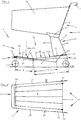
- Fig. 1 shows a shopping cart 1 stackable with the same or similar wagons 1.
- the shopping cart 1 has a chassis 2 equipped with front and rear castors 3, 4.
- the chassis 2 carries an upper storage device 5 for receiving goods with the aid of support means 21.
- the upper storage device 5 is designed as a conical basket, which carries a sliding device 7 on the back and also is equipped on the back with a pivotable flap 8 in order to enable the stacking of several shopping carts 1.
- the front side 9 and the two longitudinal sides 10 of the chassis 2 have a lower frame element 12 and an upper frame element 13, both of which are preferably formed from thick wire with a circular cross section.
- a lower parking device 6 is also mounted on a first support point 14 in a known manner.
- a cross connector 23 is provided, which forms a second support point 15 for the lower storage device 6.
- the lower storage device 6 can, depending on the type of storage and depending on its design, be raised in a known manner either at the front or at the back to likewise enable the stacking process.
- a support device 16 is provided, which is part of the chassis 2.
- the support device 16 has two support frames 17 which are arranged on the longitudinal sides 10 of the chassis 2.
- the support frames 17 are each provided on their upper side with a support means 21 and connected to the lower and to the upper frame element 12, 13.
- Each support frame 17 includes a rear frame section 18 and a front frame section 19.
- each rear frame section 18 is connected crosswise to the outer sides 20 of the lower and upper frame elements 12, 13.
- the lower frame element 12 and the upper frame element 13 are bent down a little in the area 24 located between the front and rear castors 3, 4, so that two first sections 25 and two second sections 26 are formed, which are a common kink 27 form.
- the first sections 25 of the lower and upper frame elements 12, 13 starting from the front side 9 of the chassis 2 and falling towards the rear side 32 are shorter in the example than the rising sections also leading to the rear side 32 from the common bend 27 second sections 26 of the lower and upper frame elements 12, 13, see also the inserted dimensions.
- dimension A is equal to or less than dimension B and less than dimension C, the latter being intended to show the length of the second sections (26) of the upper frame element.
- Dimensions A and B do not include the length of possible horizontal end sections of sections 25 and 26, as can be seen from the drawing.
- Each front frame section 19 of the two support frames 17 is bent toward the rear, so that in each case a support section 22 directed toward the respective rear frame section 18 is formed.
- Each support section 22 lies on the upper side 13a of the upper frame element 13 and is connected to it by welding.
- the cross-connection piece 23 can be a separate part, but it can also be designed as a common section emerging from the front frame sections 19, which merges into the support sections 22.
- a section 28a of the footprint 28 of the lower parking device 6 runs in the area of the first sections 25 at least between the bend 27 and the first support point 14 either parallel to the upper frame element 13 or steeper than the upper frame element 13.
- the upper side 29 of the section 28a lies on top the same level 30 as the upper side 13a of the upper frame element 13 in the area of the two first sections 25.
- Fig. 1 shows Fig. 2 the chassis 2 of the shopping cart 1 described above in plan view.
- the front side 9 and the two long sides 10 of the chassis 2 can be seen.
- the long sides 10 of the chassis 2 approach each other at an acute angle in the sliding direction of the shopping cart 1.
- the chassis 2 therefore has a trapezoidal plan, which lacks the longer parallel side.
- the lower support device 6 is supported and supported at the first and at the second support point 14, 15 such that the lower support device 6 is either at the level of the second Support point 15 or at the level of the first support point 14 can be raised a little.
- the lower storage device 6 is designed, for example, as a wire mesh construction.
- the storage device 6 can also be designed entirely or partially as a plastic part.
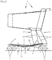
- Fig. 3 shows two nested, ie stacked shopping carts 1.
- the minimum stacking distance of both shopping carts 1 is selected such that the front casters 3 aligned in the sliding direction of the shopping trolleys 1 and the rear driving rollers 4 also aligned in the sliding direction, as shown in the drawing, of the impeller Take a distance of only 2 or 3mm from the impeller.
- the narrow stacking of several shopping carts 1 achieved thereby is possible because the rear frame sections 18 and the front frame sections 19 are arranged offset with respect to the course of the lower and the upper frame elements 12, 13.
- each rear frame section 18 is connected to the outer sides 20 of the lower and the upper frame element 12, 13, while each front frame section 19 rests on the upper side 13a of the upper frame element 13, see also description of Fig. 1 , From the drawing it can be seen that each front frame section 19 runs steeper than each rear frame section 18.
- This arrangement allows relatively wide support frames 17 to be formed, the staggered arrangement of the rear and front frame sections 18, 19 making it possible for two shopping trolleys 1 to be stacked in the stacked state
- the front frame sections 19 of the inserted shopping trolley 1 are, viewed in the sliding direction of the shopping trolley 1, between the rear frame sections 18 of the shopping trolley 1 located in front of them Common bend 27 is selected so that its wheels do not hit the lower frame element 12 of the shopping trolley 1 when moving a stack of several shopping trolleys 1.
- the lower parking device 6 of a shopping trolley 1 in front is pushed a little upwards by the chassis 2 of the rear shopping trolley 1, as can also be seen in the drawing.
- the semi-finished products suitable for producing the described shopping trolleys 1 are known from the prior art.
Landscapes
- Engineering & Computer Science (AREA)
- Chemical & Material Sciences (AREA)
- Combustion & Propulsion (AREA)
- Transportation (AREA)
- Mechanical Engineering (AREA)
- Handcart (AREA)
Description
Mit gleichen oder mit ähnlichen Wagen stapelbarer Einkaufswagen, mit einem mit vorderen und mit hinteren Fahrrollen ausgestatteten Fahrgestell, mit einer oberen Abstelleinrichtung zur Aufnahme von Ware, mit einer rückseitig befindlichen Schiebeeinrichtung und mit einer zum Abstellen weiterer Ware bestimmten unteren Abstelleinrichtung, die auf einer im vorderen Bereich des Fahrgestelles befindlichen ersten Abstützstelle gelagert ist, wobei die Vorderseite und die beiden Längsseiten des Fahrgestelles ein unteres Rahmenelement und ein oberes Rahmenelement aufweisen, deren Längsseiten sich in Schieberichtung des Einkaufswagens in einem spitzen Winkel annähern und das obere Rahmenelement in einem zwischen den vorderen und den hinteren Fahrrollen befindlichen Bereich nach unten abgeknickt ist, wobei das Fahrgestell rückseitig eine Stützeinrichtung aufweist, die mit dem unteren und mit dem oberen Rahmenelement verbunden ist und beidseitig je einen Stützrahmen aufweist, wobei jeder Stützrahmen mit einem oben angeordneten Stützmittel zum Befestigen der oberen Abstelleinrichtung ausgestattet ist, wobei ferner jeder Stützrahmen einen hinteren Rahmenabschnitt und einen vorderen Rahmenabschnitt aufweist und wobei rückseitig ein Querverbindungsstück vorgesehen ist, das eine zweite Abstützstelle für die untere Abstelleinrichtung bildet.With the same or similar trolleys stackable shopping trolleys, with a chassis equipped with front and rear castors, with an upper storage device for receiving goods, with a sliding device on the rear and with a lower storage device intended for storing other goods, which is on a front Area of the chassis located first support point, the front and the two long sides of the chassis have a lower frame element and an upper frame element, the long sides of which approach in the sliding direction of the shopping cart at an acute angle and the upper frame element in a between the front and the rear casters located area is bent down, the chassis having a support device on the back, which is connected to the lower and to the upper frame element and has a support frame on each side, each St Support frame is equipped with a support means arranged at the top for fastening the upper storage device, each support frame furthermore having a rear frame section and a front frame section and a rear connecting piece being provided on the back, which forms a second support point for the lower storage device.
Einkaufswagen dieser Ausführung bilden jene klassische Art von Wagen, die seit Jahrzehnten bekannt sind und die sich zum zusätzlichen Transport von Getränkekisten eignen. Die Getränkekisten lassen sich auf der unteren Abstelleinrichtung abstellen und transportieren.Shopping trolleys of this design form the classic type of trolley which has been known for decades and which is suitable for the additional transport of beverage crates. The beverage crates can be placed and transported on the lower storage facility.
Die Erfindung betrifft einen Einkaufswagen gemäß dem Oberbegriff von Anspruch 1. Das Dokument
Ein vergleichbares Fahrgestell für einen Einkaufswagen wird auch durch die
A comparable chassis for a shopping cart is also available through the
Das Dokument
Das Dokument
Es ist Aufgabe der Neuerung, einen Einkaufswagen der eingangs genannten Art so weiterzuentwickeln, dass die untere Abstelleinrichtung eine große, leicht be- und entladbare Abstellfläche für beispielsweise zwei Getränkekisten bildet und dass zusätzlich im Sinne der Erfindung gemäß des Dokuments
Die Lösung der Aufgabe ist im kennzeichnenden Teil des Schutzanspruchs 1 beschrieben.The solution to the problem is described in the characterizing part of
Durch die gemeinsame Abknickung des oberen und des unteren Rahmenelementes des Fahrgestelles erzielt man in vorteilhafter Weise eine Vergrößerung des zwischen der Unterseite der oberen Abstelleinrichtung und der Stellfläche der unteren Abstelleinrichtung gelegenen Raumes. Das erlaubt ein bequemes Be- und Entladen der unteren Abstelleinrichtung mit Getränkekisten. Begünstigt wird dies ferner dadurch, dass jener Abschnitt der unteren Abstelleinrichtung, der sich im Bereich der zur Rückseite hin abfallenden ersten Abschnitte des Fahrgestelles befindet, entweder parallel zum oberen Rahmenelement oder leicht steiler als dieses angeordnet ist. Es empfiehlt sich sogar, den eben beschriebenen Abschnitt so anzuordnen, dass die Oberfläche dieses Abschnitts und die Oberseiten der beiden ersten Abschnitte auf einer gemeinsamen Ebene liegen.The joint kinking of the upper and lower frame elements of the chassis advantageously results in an enlargement of the space located between the underside of the upper storage device and the footprint of the lower storage device. This allows convenient loading and unloading of the lower storage facility with beverage crates. This is further favored by the fact that that section of the lower parking device, which is located in the area of the first sections of the chassis sloping towards the rear, is arranged either parallel to the upper frame element or slightly steeper than this. It is even advisable to arrange the section just described so that the surface of this section and the tops of the first two sections lie on a common plane.
Ein ganz enges Stapeln mehrerer Einkaufswagen wird deshalb erzielt, weil die hinteren und die vorderen Rahmenabschnitte der Stützeinrichtungen im Versatz so angeordnet sind, dass sich in gestapeltem Zustand zweier Einkaufswagen die vorderen Rahmenabschnitte eines rückwärtig eingeschobenen Einkaufswagens zwischen den hinteren Rahmenabschnitten des vorausbefindlichen Einkaufswagens befinden, was ebenfalls als Vorteil zu werten ist,A very tight stacking of several shopping carts is achieved because the rear and the front frame sections of the support devices are arranged in an offset such that, when two shopping carts are stacked, the front frame sections of a shopping cart inserted in the rear are located between the rear frame sections of the preceding shopping cart, which is also the case can be seen as an advantage
Ein weiterer Vorteil ergibt sich, wenn die beiden Stützabschnitte der vorderen Rahmenabschnitte zur Bildung des Querverbindungsstücks benutzt werden, welches bekanntlich als weitere Auflage für die untere Abstelleinrichtung vorgesehen ist. Da die Stützabschnitte der vorderen Rahmenabschnitte zu den hinteren Rahmenabschnitten gerichtet sind, lassen diese sich in vorteilhafter Weise so weit nach hinten führen, dass auch die untere Abstelleinrichtung sehr lang gestaltet werden kann, um zwei Getränkekisten sicher aufnehmen zu können.A further advantage results if the two support sections of the front frame sections are used to form the cross-connecting piece, which is known to be provided as a further support for the lower storage device. Since the support sections of the front frame sections are directed towards the rear frame sections, these can advantageously be guided so far back that the lower storage device can also be made very long in order to be able to safely hold two beverage crates.
Die Neuerung wird anhand eines Ausführungsbeispiels näher erläutert, wobei mögliche Alternativen angesprochen und deren Vorteile beschrieben sind. Es zeigt
- Fig. 1
- einen Einkaufswagen in Seitenansicht;
- Fig. 2
- das Fahrgestell des in
Fig.1 beschriebenen Einkaufswagens in Draufsicht sowie - Fig. 3
- in Seitenansicht zwei Einkaufswagen gemäß
Fig. 1 in gestapeltem Zustand.
- Fig. 1
- a shopping cart in side view;
- Fig. 2
- the chassis of the in
Fig.1 described shopping cart in top view as well - Fig. 3
- Side view of two shopping trolleys
Fig. 1 in stacked condition.
Ergänzend zu
Die zur Herstellung der beschriebenen Einkaufswagen 1 geeigneten Halbzeuge sind durch den Stand der Technik bekannt.The semi-finished products suitable for producing the described
Claims (9)
- Shopping trolley (1) which is stackable with the same or with similar trollies, having an underframe (2) equipped with front and with rear rollers (3, 4), having an upper storage device (5) for receiving goods, having a pushing device (7) located on the rear side and having a lower storage device (6) which is mounted on a first support point (14) located in the front region (11) of the underframe (2), wherein the front side (9) and the two longitudinal sides (10) of the underframe (2) have a lower frame element (12) and an upper frame element (13), the longitudinal sides (10) of which come closer at an acute angle in the pushing direction of the shopping trolley (1) and the upper frame element (13) is bent downwards at both longitudinal sides (10) and in a region (24) located between the front and the rear rollers (3, 4), wherein the underframe (2) has a support device (16) on the rear side which is connected to the lower and to the upper frame element (12, 13) and has on each of the two sides a support frame (17), wherein each support frame (17) is equipped with a support means (21) arranged at the top for attaching the upper storage device (5), wherein furthermore, each support frame (17) has a rear frame section (18) and a front frame section (19) and wherein on the rear side a transverse connecting piece (23) is provided which forms a second support point (15) for the lower storage device (6), characterised in that the lower frame element (12) is also bent downwards at both longitudinal sides (10) in the region (24) located between the front and the rear rollers (3, 4) and, seen in side view, forms a common bend (27) with the upper frame element (13), wherein respectively a first section (25) falling away towards the rear side (32) and respectively a second section (26) rising towards the rear side (32) are formed by the bend (27) at each longitudinal side (10) and in that a section (28a) of the charging space (28) of the lower storage device (6) located between the common bend (27) and the first support point (14), either runs parallel to the upper frame element (13) or is arranged to be steeper than the upper frame element (13).
- Shopping trolley according to claim 1, characterised in that each first section (25) is either the same length or shorter than each second section (26).
- Shopping trolley according to claim 1, characterised in that the transverse connecting piece (23) is formed as a common section coming from the front frame sections (19).
- Shopping trolley according to claim 3, characterised in that the transverse connecting piece (23) is located between the rear and the front frame sections (18, 19).
- Shopping trolley according to claim 1, characterised in that the section (28a) of the charging space (28) of the lower storage device (6) lies with its upper side (29) on the same plane (30) as the upper sides (13a) of the two first sections (25).
- Shopping trolley according to claim 1, characterised in that each front frame section (19) runs more steeply than each rear frame section (18).
- Shopping trolley according to claim 1, characterised in that in the stacked state of two shopping trollies (1), and seen from the side, the front frame sections (19) of a rearwardly pushed-in shopping trolley (1) overlap with the rear frame sections (18) of the preceding shopping trolley (1) or are congruent with them.
- Shopping trolley according to claim 1, characterised in that in the stacked state of two shopping trollies (1), and seen in the pushing direction thereof, the front frame sections (19) of the pushed-in shopping trolley (1) are located between the rear frame sections (18) of the preceding shopping trolley (1).
- Shopping trolley according to claim 1, characterised in that the lower frame element (12) is bent downwards only so far that in a stack of several shopping trollies (1), the front and the rear rollers (3, 4) can be rotated about their perpendicular axis.
Applications Claiming Priority (1)
| Application Number | Priority Date | Filing Date | Title |
|---|---|---|---|
| DE202017100528.3U DE202017100528U1 (en) | 2017-02-01 | 2017-02-01 | Stackable shopping trolleys with the same or similar trolley |
Publications (2)
| Publication Number | Publication Date |
|---|---|
| EP3357787A1 EP3357787A1 (en) | 2018-08-08 |
| EP3357787B1 true EP3357787B1 (en) | 2019-12-18 |
Family
ID=58639680
Family Applications (1)
| Application Number | Title | Priority Date | Filing Date |
|---|---|---|---|
| EP18152700.3A Active EP3357787B1 (en) | 2017-02-01 | 2018-01-22 | Shopping cart stackable with equal or similar carts |
Country Status (2)
| Country | Link |
|---|---|
| EP (1) | EP3357787B1 (en) |
| DE (1) | DE202017100528U1 (en) |
Families Citing this family (1)
| Publication number | Priority date | Publication date | Assignee | Title |
|---|---|---|---|---|
| CN111071320B (en) * | 2019-12-27 | 2022-04-05 | 合肥云内动力有限公司 | Layer frame push-and-pull turnover vehicle |
Family Cites Families (7)
| Publication number | Priority date | Publication date | Assignee | Title |
|---|---|---|---|---|
| DE8714522U1 (en) * | 1987-10-31 | 1988-05-05 | Rudolf Wanzl Kg, 8874 Leipheim, De | |
| DE8903451U1 (en) * | 1988-12-06 | 1989-05-11 | Manss, August, 3500 Kassel, De | |
| DE19626995A1 (en) | 1996-07-04 | 1998-01-08 | Wanzl Metallwarenfabrik Kg | Chassis for a hand-movable trolley |
| DE29809776U1 (en) * | 1998-05-30 | 1998-07-30 | Wanzl Metallwarenfabrik Kg | Stackable shopping cart |
| EP1693809A1 (en) | 2005-02-17 | 2006-08-23 | All4Retail SA | Shopping trolley and tracking system for shopping trolley |
| DE102005017386B4 (en) | 2005-04-14 | 2009-01-15 | Wanzl Metallwarenfabrik Gmbh | Stackable shopping cart |
| EA022065B1 (en) | 2010-04-13 | 2015-10-30 | Мартин Эберляйн | Stack comprising a number of shopping carts for self-service stores (variants) |
-
2017
- 2017-02-01 DE DE202017100528.3U patent/DE202017100528U1/en not_active Expired - Lifetime
-
2018
- 2018-01-22 EP EP18152700.3A patent/EP3357787B1/en active Active
Non-Patent Citations (1)
| Title |
|---|
| None * |
Also Published As
| Publication number | Publication date |
|---|---|
| EP3357787A1 (en) | 2018-08-08 |
| DE202017100528U1 (en) | 2017-04-06 |
Similar Documents
| Publication | Publication Date | Title |
|---|---|---|
| DE2656921A1 (en) | TRANSPORT CART | |
| EP1819571A2 (en) | Transport device for stacked goods requiring transport | |
| EP2520512A1 (en) | Runner pallet, in particular for transport and storage container for fluids | |
| EP2907723A1 (en) | Transport trolley | |
| EP0141398B1 (en) | Nestable shopping trolley | |
| EP3357787B1 (en) | Shopping cart stackable with equal or similar carts | |
| EP2683590B1 (en) | Shopping trolley | |
| WO2017152893A1 (en) | Transporting device that can be moved by hand | |
| DE102010025079B4 (en) | Shopping venture | |
| WO2005085035A2 (en) | Stackable shopping trolley | |
| DE4419582C2 (en) | Transport trolleys, in particular shopping trolleys | |
| DE102009056419A1 (en) | Load part for industrial truck, has carriage rod comprising two carriage elements, and fork arms extended below or through front plate and connected with one of carriage elements, where fork arms are manufactured as single-piece | |
| EP0672569B1 (en) | Shopping trolley | |
| DE202010010891U1 (en) | pallet | |
| WO2001000475A1 (en) | Stackable transport cart | |
| EP2615008B1 (en) | Manually moveable transport trolley, which can be stacked with the same trolley | |
| EP2335998A2 (en) | Collapsible drink crate storage for a shopping trolley | |
| DE102006050648B3 (en) | Device turning over sheet components between two presses and exchanging gripping tools, includes carriers with arms and clamping mechanisms running on elevated beam | |
| EP1084930B1 (en) | Nestable transport trolley for the transport of boards to be placed on end | |
| DE10332868B4 (en) | Shopping venture | |
| EP2650192A2 (en) | Transport trolley | |
| DE4436804A1 (en) | Shopping trolley | |
| DE4312392A1 (en) | Shopping venture | |
| DE102016104262B3 (en) | Reusable transport box | |
| DE3835586A1 (en) | SHOPPING VENTURE |
Legal Events
| Date | Code | Title | Description |
|---|---|---|---|
| PUAI | Public reference made under article 153(3) epc to a published international application that has entered the european phase |
Free format text: ORIGINAL CODE: 0009012 |
|
| STAA | Information on the status of an ep patent application or granted ep patent |
Free format text: STATUS: THE APPLICATION HAS BEEN PUBLISHED |
|
| AK | Designated contracting states |
Kind code of ref document: A1 Designated state(s): AL AT BE BG CH CY CZ DE DK EE ES FI FR GB GR HR HU IE IS IT LI LT LU LV MC MK MT NL NO PL PT RO RS SE SI SK SM TR |
|
| AX | Request for extension of the european patent |
Extension state: BA ME |
|
| STAA | Information on the status of an ep patent application or granted ep patent |
Free format text: STATUS: REQUEST FOR EXAMINATION WAS MADE |
|
| 17P | Request for examination filed |
Effective date: 20190208 |
|
| RBV | Designated contracting states (corrected) |
Designated state(s): AL AT BE BG CH CY CZ DE DK EE ES FI FR GB GR HR HU IE IS IT LI LT LU LV MC MK MT NL NO PL PT RO RS SE SI SK SM TR |
|
| GRAP | Despatch of communication of intention to grant a patent |
Free format text: ORIGINAL CODE: EPIDOSNIGR1 |
|
| STAA | Information on the status of an ep patent application or granted ep patent |
Free format text: STATUS: GRANT OF PATENT IS INTENDED |
|
| INTG | Intention to grant announced |
Effective date: 20190801 |
|
| GRAS | Grant fee paid |
Free format text: ORIGINAL CODE: EPIDOSNIGR3 |
|
| GRAA | (expected) grant |
Free format text: ORIGINAL CODE: 0009210 |
|
| STAA | Information on the status of an ep patent application or granted ep patent |
Free format text: STATUS: THE PATENT HAS BEEN GRANTED |
|
| AK | Designated contracting states |
Kind code of ref document: B1 Designated state(s): AL AT BE BG CH CY CZ DE DK EE ES FI FR GB GR HR HU IE IS IT LI LT LU LV MC MK MT NL NO PL PT RO RS SE SI SK SM TR |
|
| REG | Reference to a national code |
Ref country code: CH Ref legal event code: EP |
|
| REG | Reference to a national code |
Ref country code: DE Ref legal event code: R096 Ref document number: 502018000502 Country of ref document: DE |
|
| REG | Reference to a national code |
Ref country code: IE Ref legal event code: FG4D Free format text: LANGUAGE OF EP DOCUMENT: GERMAN |
|
| REG | Reference to a national code |
Ref country code: AT Ref legal event code: REF Ref document number: 1214300 Country of ref document: AT Kind code of ref document: T Effective date: 20200115 |
|
| REG | Reference to a national code |
Ref country code: NL Ref legal event code: MP Effective date: 20191218 |
|
| PG25 | Lapsed in a contracting state [announced via postgrant information from national office to epo] |
Ref country code: LT Free format text: LAPSE BECAUSE OF FAILURE TO SUBMIT A TRANSLATION OF THE DESCRIPTION OR TO PAY THE FEE WITHIN THE PRESCRIBED TIME-LIMIT Effective date: 20191218 Ref country code: NO Free format text: LAPSE BECAUSE OF FAILURE TO SUBMIT A TRANSLATION OF THE DESCRIPTION OR TO PAY THE FEE WITHIN THE PRESCRIBED TIME-LIMIT Effective date: 20200318 Ref country code: LV Free format text: LAPSE BECAUSE OF FAILURE TO SUBMIT A TRANSLATION OF THE DESCRIPTION OR TO PAY THE FEE WITHIN THE PRESCRIBED TIME-LIMIT Effective date: 20191218 Ref country code: SE Free format text: LAPSE BECAUSE OF FAILURE TO SUBMIT A TRANSLATION OF THE DESCRIPTION OR TO PAY THE FEE WITHIN THE PRESCRIBED TIME-LIMIT Effective date: 20191218 Ref country code: FI Free format text: LAPSE BECAUSE OF FAILURE TO SUBMIT A TRANSLATION OF THE DESCRIPTION OR TO PAY THE FEE WITHIN THE PRESCRIBED TIME-LIMIT Effective date: 20191218 Ref country code: BG Free format text: LAPSE BECAUSE OF FAILURE TO SUBMIT A TRANSLATION OF THE DESCRIPTION OR TO PAY THE FEE WITHIN THE PRESCRIBED TIME-LIMIT Effective date: 20200318 Ref country code: GR Free format text: LAPSE BECAUSE OF FAILURE TO SUBMIT A TRANSLATION OF THE DESCRIPTION OR TO PAY THE FEE WITHIN THE PRESCRIBED TIME-LIMIT Effective date: 20200319 |
|
| REG | Reference to a national code |
Ref country code: LT Ref legal event code: MG4D |
|
| PG25 | Lapsed in a contracting state [announced via postgrant information from national office to epo] |
Ref country code: HR Free format text: LAPSE BECAUSE OF FAILURE TO SUBMIT A TRANSLATION OF THE DESCRIPTION OR TO PAY THE FEE WITHIN THE PRESCRIBED TIME-LIMIT Effective date: 20191218 Ref country code: RS Free format text: LAPSE BECAUSE OF FAILURE TO SUBMIT A TRANSLATION OF THE DESCRIPTION OR TO PAY THE FEE WITHIN THE PRESCRIBED TIME-LIMIT Effective date: 20191218 |
|
| PG25 | Lapsed in a contracting state [announced via postgrant information from national office to epo] |
Ref country code: AL Free format text: LAPSE BECAUSE OF FAILURE TO SUBMIT A TRANSLATION OF THE DESCRIPTION OR TO PAY THE FEE WITHIN THE PRESCRIBED TIME-LIMIT Effective date: 20191218 |
|
| PG25 | Lapsed in a contracting state [announced via postgrant information from national office to epo] |
Ref country code: PT Free format text: LAPSE BECAUSE OF FAILURE TO SUBMIT A TRANSLATION OF THE DESCRIPTION OR TO PAY THE FEE WITHIN THE PRESCRIBED TIME-LIMIT Effective date: 20200513 Ref country code: RO Free format text: LAPSE BECAUSE OF FAILURE TO SUBMIT A TRANSLATION OF THE DESCRIPTION OR TO PAY THE FEE WITHIN THE PRESCRIBED TIME-LIMIT Effective date: 20191218 Ref country code: NL Free format text: LAPSE BECAUSE OF FAILURE TO SUBMIT A TRANSLATION OF THE DESCRIPTION OR TO PAY THE FEE WITHIN THE PRESCRIBED TIME-LIMIT Effective date: 20191218 Ref country code: CZ Free format text: LAPSE BECAUSE OF FAILURE TO SUBMIT A TRANSLATION OF THE DESCRIPTION OR TO PAY THE FEE WITHIN THE PRESCRIBED TIME-LIMIT Effective date: 20191218 Ref country code: EE Free format text: LAPSE BECAUSE OF FAILURE TO SUBMIT A TRANSLATION OF THE DESCRIPTION OR TO PAY THE FEE WITHIN THE PRESCRIBED TIME-LIMIT Effective date: 20191218 |
|
| PG25 | Lapsed in a contracting state [announced via postgrant information from national office to epo] |
Ref country code: IS Free format text: LAPSE BECAUSE OF FAILURE TO SUBMIT A TRANSLATION OF THE DESCRIPTION OR TO PAY THE FEE WITHIN THE PRESCRIBED TIME-LIMIT Effective date: 20200418 Ref country code: SM Free format text: LAPSE BECAUSE OF FAILURE TO SUBMIT A TRANSLATION OF THE DESCRIPTION OR TO PAY THE FEE WITHIN THE PRESCRIBED TIME-LIMIT Effective date: 20191218 Ref country code: SK Free format text: LAPSE BECAUSE OF FAILURE TO SUBMIT A TRANSLATION OF THE DESCRIPTION OR TO PAY THE FEE WITHIN THE PRESCRIBED TIME-LIMIT Effective date: 20191218 |
|
| REG | Reference to a national code |
Ref country code: DE Ref legal event code: R097 Ref document number: 502018000502 Country of ref document: DE |
|
| PG25 | Lapsed in a contracting state [announced via postgrant information from national office to epo] |
Ref country code: MC Free format text: LAPSE BECAUSE OF FAILURE TO SUBMIT A TRANSLATION OF THE DESCRIPTION OR TO PAY THE FEE WITHIN THE PRESCRIBED TIME-LIMIT Effective date: 20191218 |
|
| REG | Reference to a national code |
Ref country code: BE Ref legal event code: MM Effective date: 20200131 |
|
| PLBE | No opposition filed within time limit |
Free format text: ORIGINAL CODE: 0009261 |
|
| STAA | Information on the status of an ep patent application or granted ep patent |
Free format text: STATUS: NO OPPOSITION FILED WITHIN TIME LIMIT |
|
| PG25 | Lapsed in a contracting state [announced via postgrant information from national office to epo] |
Ref country code: DK Free format text: LAPSE BECAUSE OF FAILURE TO SUBMIT A TRANSLATION OF THE DESCRIPTION OR TO PAY THE FEE WITHIN THE PRESCRIBED TIME-LIMIT Effective date: 20191218 Ref country code: ES Free format text: LAPSE BECAUSE OF FAILURE TO SUBMIT A TRANSLATION OF THE DESCRIPTION OR TO PAY THE FEE WITHIN THE PRESCRIBED TIME-LIMIT Effective date: 20191218 Ref country code: LU Free format text: LAPSE BECAUSE OF NON-PAYMENT OF DUE FEES Effective date: 20200122 |
|
| 26N | No opposition filed |
Effective date: 20200921 |
|
| PG25 | Lapsed in a contracting state [announced via postgrant information from national office to epo] |
Ref country code: SI Free format text: LAPSE BECAUSE OF FAILURE TO SUBMIT A TRANSLATION OF THE DESCRIPTION OR TO PAY THE FEE WITHIN THE PRESCRIBED TIME-LIMIT Effective date: 20191218 Ref country code: BE Free format text: LAPSE BECAUSE OF NON-PAYMENT OF DUE FEES Effective date: 20200131 |
|
| PG25 | Lapsed in a contracting state [announced via postgrant information from national office to epo] |
Ref country code: IE Free format text: LAPSE BECAUSE OF NON-PAYMENT OF DUE FEES Effective date: 20200122 Ref country code: FR Free format text: LAPSE BECAUSE OF NON-PAYMENT OF DUE FEES Effective date: 20200218 Ref country code: IT Free format text: LAPSE BECAUSE OF FAILURE TO SUBMIT A TRANSLATION OF THE DESCRIPTION OR TO PAY THE FEE WITHIN THE PRESCRIBED TIME-LIMIT Effective date: 20191218 |
|
| PG25 | Lapsed in a contracting state [announced via postgrant information from national office to epo] |
Ref country code: PL Free format text: LAPSE BECAUSE OF FAILURE TO SUBMIT A TRANSLATION OF THE DESCRIPTION OR TO PAY THE FEE WITHIN THE PRESCRIBED TIME-LIMIT Effective date: 20191218 |
|
| PGFP | Annual fee paid to national office [announced via postgrant information from national office to epo] |
Ref country code: DE Payment date: 20210310 Year of fee payment: 4 |
|
| REG | Reference to a national code |
Ref country code: CH Ref legal event code: PL |
|
| PG25 | Lapsed in a contracting state [announced via postgrant information from national office to epo] |
Ref country code: LI Free format text: LAPSE BECAUSE OF NON-PAYMENT OF DUE FEES Effective date: 20210131 Ref country code: CH Free format text: LAPSE BECAUSE OF NON-PAYMENT OF DUE FEES Effective date: 20210131 |
|
| PG25 | Lapsed in a contracting state [announced via postgrant information from national office to epo] |
Ref country code: TR Free format text: LAPSE BECAUSE OF FAILURE TO SUBMIT A TRANSLATION OF THE DESCRIPTION OR TO PAY THE FEE WITHIN THE PRESCRIBED TIME-LIMIT Effective date: 20191218 Ref country code: MT Free format text: LAPSE BECAUSE OF FAILURE TO SUBMIT A TRANSLATION OF THE DESCRIPTION OR TO PAY THE FEE WITHIN THE PRESCRIBED TIME-LIMIT Effective date: 20191218 Ref country code: CY Free format text: LAPSE BECAUSE OF FAILURE TO SUBMIT A TRANSLATION OF THE DESCRIPTION OR TO PAY THE FEE WITHIN THE PRESCRIBED TIME-LIMIT Effective date: 20191218 |
|
| PG25 | Lapsed in a contracting state [announced via postgrant information from national office to epo] |
Ref country code: MK Free format text: LAPSE BECAUSE OF FAILURE TO SUBMIT A TRANSLATION OF THE DESCRIPTION OR TO PAY THE FEE WITHIN THE PRESCRIBED TIME-LIMIT Effective date: 20191218 |
|
| REG | Reference to a national code |
Ref country code: DE Ref legal event code: R119 Ref document number: 502018000502 Country of ref document: DE |
|
| GBPC | Gb: european patent ceased through non-payment of renewal fee |
Effective date: 20220122 |
|
| PG25 | Lapsed in a contracting state [announced via postgrant information from national office to epo] |
Ref country code: GB Free format text: LAPSE BECAUSE OF NON-PAYMENT OF DUE FEES Effective date: 20220122 Ref country code: DE Free format text: LAPSE BECAUSE OF NON-PAYMENT OF DUE FEES Effective date: 20220802 |
|
| REG | Reference to a national code |
Ref country code: AT Ref legal event code: MM01 Ref document number: 1214300 Country of ref document: AT Kind code of ref document: T Effective date: 20230122 |
|
| PG25 | Lapsed in a contracting state [announced via postgrant information from national office to epo] |
Ref country code: AT Free format text: LAPSE BECAUSE OF NON-PAYMENT OF DUE FEES Effective date: 20230122 |
|
| PG25 | Lapsed in a contracting state [announced via postgrant information from national office to epo] |
Ref country code: AT Free format text: LAPSE BECAUSE OF NON-PAYMENT OF DUE FEES Effective date: 20230122 |