EP3357713A1 - Tire for construction vehicles - Google Patents
Tire for construction vehicles Download PDFInfo
- Publication number
- EP3357713A1 EP3357713A1 EP16851874.4A EP16851874A EP3357713A1 EP 3357713 A1 EP3357713 A1 EP 3357713A1 EP 16851874 A EP16851874 A EP 16851874A EP 3357713 A1 EP3357713 A1 EP 3357713A1
- Authority
- EP
- European Patent Office
- Prior art keywords
- carcass
- construction vehicle
- vehicle tire
- tire
- folded portion
- Prior art date
- Legal status (The legal status is an assumption and is not a legal conclusion. Google has not performed a legal analysis and makes no representation as to the accuracy of the status listed.)
- Granted
Links
Images


Classifications
-
- B—PERFORMING OPERATIONS; TRANSPORTING
- B60—VEHICLES IN GENERAL
- B60C—VEHICLE TYRES; TYRE INFLATION; TYRE CHANGING; CONNECTING VALVES TO INFLATABLE ELASTIC BODIES IN GENERAL; DEVICES OR ARRANGEMENTS RELATED TO TYRES
- B60C15/00—Tyre beads, e.g. ply turn-up or overlap
- B60C15/0009—Tyre beads, e.g. ply turn-up or overlap features of the carcass terminal portion
-
- B—PERFORMING OPERATIONS; TRANSPORTING
- B60—VEHICLES IN GENERAL
- B60C—VEHICLE TYRES; TYRE INFLATION; TYRE CHANGING; CONNECTING VALVES TO INFLATABLE ELASTIC BODIES IN GENERAL; DEVICES OR ARRANGEMENTS RELATED TO TYRES
- B60C15/00—Tyre beads, e.g. ply turn-up or overlap
- B60C15/0009—Tyre beads, e.g. ply turn-up or overlap features of the carcass terminal portion
- B60C15/0054—Tyre beads, e.g. ply turn-up or overlap features of the carcass terminal portion with ply turn-up portion parallel and adjacent to carcass main portion
-
- B—PERFORMING OPERATIONS; TRANSPORTING
- B60—VEHICLES IN GENERAL
- B60C—VEHICLE TYRES; TYRE INFLATION; TYRE CHANGING; CONNECTING VALVES TO INFLATABLE ELASTIC BODIES IN GENERAL; DEVICES OR ARRANGEMENTS RELATED TO TYRES
- B60C15/00—Tyre beads, e.g. ply turn-up or overlap
- B60C15/0009—Tyre beads, e.g. ply turn-up or overlap features of the carcass terminal portion
- B60C15/0063—Tyre beads, e.g. ply turn-up or overlap features of the carcass terminal portion with ply turn-up portion diverging from carcass main portion
-
- B—PERFORMING OPERATIONS; TRANSPORTING
- B60—VEHICLES IN GENERAL
- B60C—VEHICLE TYRES; TYRE INFLATION; TYRE CHANGING; CONNECTING VALVES TO INFLATABLE ELASTIC BODIES IN GENERAL; DEVICES OR ARRANGEMENTS RELATED TO TYRES
- B60C15/00—Tyre beads, e.g. ply turn-up or overlap
- B60C15/0009—Tyre beads, e.g. ply turn-up or overlap features of the carcass terminal portion
- B60C2015/009—Height of the carcass terminal portion defined in terms of a numerical value or ratio in proportion to section height
-
- B—PERFORMING OPERATIONS; TRANSPORTING
- B60—VEHICLES IN GENERAL
- B60C—VEHICLE TYRES; TYRE INFLATION; TYRE CHANGING; CONNECTING VALVES TO INFLATABLE ELASTIC BODIES IN GENERAL; DEVICES OR ARRANGEMENTS RELATED TO TYRES
- B60C2200/00—Tyres specially adapted for particular applications
- B60C2200/06—Tyres specially adapted for particular applications for heavy duty vehicles
- B60C2200/065—Tyres specially adapted for particular applications for heavy duty vehicles for construction vehicles
Definitions
- the present invention relates to a construction vehicle tire, in particular, a construction vehicle tire in which durability of a bead portion is improved.
- a large load is applied to a construction vehicle tire mounted to a construction vehicle that travels on an uneven road surface in a construction site and has a large loading mount, and therefore it is especially important to improve durability of a bead portion in order to lengthen a tire life.
- the distance between the cords is set to be the minimum near the bead core, and then the distance is increased toward the outer side in the tire radial direction and is set to be the maximum at a predetermined height position from the bead portion.
- the compression strain generated in the carcass folded portion due to vertical force (Fz) can be reduced, however in an actual use environment, the compression strain is also generated in the carcass folded portion due to lateral force (Fy). That is, an inflection point of the carcass folded portion with respect to the compression strain in a state in which the lateral force is large is shifted from an inflection point of the carcass folded portion in a state in which the lateral force is small, and thereby it is found that the compression strain might not be always reduced effectively.
- an object of the present invention is, in consideration of the problem described above, to provide a construction vehicle tire capable of reducing compression strain generated in a carcass folded portion even in a state closer to an actual use environment in which large lateral force is input, and capable of improving durability of a bead portion.
- a first feature of the present invention is that, in a construction vehicle tire (construction vehicle tire 1) including a carcass body portion (carcass body portion 40) formed by a covered carcass cord (carcass cord 31), and a carcass folded portion (carcass folded portion 50) continued to the carcass body portion and folded at a bead core (bead core 61) from an inner side in a tire width direction toward an outer side in the tire width direction, the carcass folded portion being formed by a covered carcass cord, a distance between cords, which is defined by a distance between the carcass cord of the carcass body portion and the carcass cord of the carcass folded portion, becomes smaller from the bead core toward an outer side in a tire radial direction to a minimum value a, and after the distance between the cords becomes the minimum value a, the distance between the cords becomes larger toward the outer side in the tire radial direction to the maximum value b, and when the construction vehicle tire is mounted to an applicable rim (wheel rim 100), a height
- a distance L1 along the carcass cord of the carcass folded portion between a position of the minimum value a and a position of the maximum value b may be longer than a distance L2 along the carcass cord of the carcass folded portion between the position of the maximum value b and an end portion (end portion 51) at the outer side in the tire radial direction of the carcass folded portion.
- the number of the portions of the maximum value b may be only one between the bead core and the end portion at the outer side in the tire radial direction of the carcass folded portion.
- a ratio b/a of the minimum value a and the maximum value b may be equal to or more than 1.10 and less than 2.00.
- a second feature of the present invention is that, in a construction vehicle tire (construction vehicle tire 1) including a carcass body portion (carcass body portion 40) formed by a covered carcass cord (carcass cord 31), and a carcass folded portion (carcass folded portion 50) continued to the carcass body portion and folded at a bead core (bead core 61) from an inner side in a tire width direction toward an outer side in the tire width direction, the carcass folded portion being formed by a covered carcass cord, a distance between cords, which is defined by a distance between the carcass cord of the carcass body portion and the carcass cord of the carcass folded portion, becomes smaller from the bead core toward an outer side in a tire radial direction to a minimum value a, and after the distance between the cords becomes the minimum value a, the distance between the cords becomes larger toward the outer side in the tire radial direction to the maximum value b, and when the construction vehicle tire is mounted to an applicable rim (wheel rim 100), a height
- a height CH of a carcass line of a tread portion of the construction vehicle tire from the base line of the applicable rim and a height PE of an end portion of the carcass folded portion from the base line of the applicable rim may fulfill a relation of 0.50 ⁇ PE/CH ⁇ 0.58.
- a crossing angle ⁇ between a straight line SL1 passing a position of the carcass cord of the carcass body portion corresponding to the minimum value a and a position of the carcass cord of the carcass body portion corresponding to the maximum value b, and a straight line SL2 passing a position of the carcass cord of the carcass folded portion corresponding to the minimum value a and a position of the carcass cord of the carcass folded portion corresponding to the maximum value b may fulfill a relation of 2.00° ⁇ ⁇ ⁇ 5.00°.
- the number of the portions of the maximum value b may be only one between the bead core and the end portion at the outer side in the tire radial direction of the carcass folded portion.
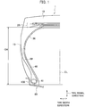
- Fig. 1 is a cross-sectional view along a tire width direction and a tire radial direction illustrating a part of a construction vehicle tire 1 according to the present embodiment.
- the construction vehicle tire 1 is formed symmetry in a lateral direction with respect to a tire equatorial line CL.
- the construction vehicle tire 1 is preferably used as a construction vehicle tire used in, for example, a dump truck, an articulate dump truck, or a wheel loader that travels on crushed stones, or in a mine or a dam construction site.
- the construction vehicle tire 1 is provided with a tread portion 10 that contacts with a road surface, a side wall portion 15 continued to the tread portion 10 and arranged at an inner side in the tire radial direction with respect to the tread portion 10, and a bead portion 60 continued to the side wall portion 15 and arranged at the inner side in the tire radial direction with respect to the side wall portion 15.
- a belt layer 20 formed by a plurality of belts (for example, 4 to 6 sheets) with a cord is arranged at the inner side in the tire radial direction of the tread portion 10. Further, a pattern (not shown) in accordance with a use environment of the construction vehicle tire 1 or a kind of a construction vehicle to which the construction vehicle tire 1 is mounted is formed in the tread portion 10.
- a carcass layer 30 that forms a frame of the construction vehicle tire 1 is arranged at the inner side in the tire radial direction of the belt layer 20 between a pair of right and left bead cores 61.
- the carcass layer 30 is formed as a radial structure having a carcass cord 31 (not shown in FIG. 1 , see FIG. 2 ) radially arranged along the tire radial direction.
- a bias structure in which the carcass cord is arranged to cross the tire radial direction may be adopted.
- the construction vehicle tire 1 is formed as a pneumatic tire.
- the gas filled into the construction vehicle tire 1 mounted to a wheel rim 100 is not limited to air, and therefore an inert gas such as a nitrogen gas may be filled. Further, a liquid for cooling (coolant) may be filled.
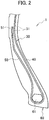
- Fig. 2 is an enlarged cross-sectional view illustrating the bead portion 60 of the construction vehicle tire 1.
- the carcass layer 30 is formed by a carcass body portion 40 and a carcass folded portion 50.
- Each of the carcass body portion 40 and the carcass folded portion 50 has a structure in which the carcass cord 31 is covered with rubber.
- the carcass body portion 40 is located at a portion from the tread portion 10 (see Fig. 1 ) to a bead core 61 so as to form a body portion of the carcass layer 30.
- the carcass folded portion 50 is continued to the carcass body portion 40 and folded at the bead core 61 from an inner side in the tire width direction toward an outer side in the tire width direction.
- the carcass folded portion 50 is extended from the bead core 61 toward the outer side in the tire radial direction.
- An end portion 51 of the carcass folded portion 50 terminates in the side wall portion 15.
- Fig. 3 shows a specific positional relation between the carcass body portion 40 and the carcass folded portion 50 of the construction vehicle tire 1.
- a distance between cords which is defined by a distance between the carcass cord 31 of the carcass body portion 40 and the carcass cord 31 of the carcass folded portion 50, becomes smaller from the bead core 61 toward the outer side in the tire radial direction to a minimum value a.
- the distance between the cords becomes larger toward the outer side in the tire radial direction to a maximum value b.
- the distance between the cords is defined by a distance (gap), in a section along the tire width direction and the tire radial direction as shown in Fig. 2 , between the carcass cord 31 of the carcass body portion 40 and the carcass cord 31 of the carcass folded portion 50 with respect to a tangent line of the carcass cord 31 of the carcass body portion 40 as a reference. More specifically, the distance between the cords is defined by a distance between a center in a thickness direction of the carcass cord 31 of the carcass body portion 40 and a center in a thickness direction of the carcass cord 31 of the carcass folded portion 50.
- a height HA of the carcass cord 31 of the carcass body portion 40 corresponding to the minimum value a from a base line BL of the wheel rim 100, a height HB of the carcass cord 31 of the carcass body portion 40 corresponding to the maximum value b from the base line BL, and a height HF of a rim flange 110 of the wheel rim 100 from the base line BL fulfill the following relations.
- the base line BL is a straight line parallel to a rotation axis of the wheel rim 100 and passing an end portion (bead heel) at the outer side in the tire radial direction of the bead portion 60.
- the applicable rim is, for example, a wheel rim having a standard size defined in Year Book of Japan Automobile Tyre Manufacturers Association (JATMA), and the heights HA, HB, HF are measured in a state in which measurement conditions (mounting to the applicable rim, setting of defined inner pressure, setting temperature or the like) defined in JATMA are fulfilled.
- JATMA Year Book of Japan Automobile Tyre Manufacturers Association
- other standard TRA, ETRTO or the like
- Fig. 4 shows a specific shape of the carcass folded portion 50 of the construction vehicle tire 1.
- a distance along the carcass cord 31 of the carcass folded portion 50 between a position of the minimum value a and a position of the maximum value b is defined as a distance L1.
- a distance along the carcass cord 31 of the carcass folded portion 50 between the position of the maximum value b and the end portion 51 at the outer side in the tire radial direction of the carcass folded portion 50 is defined as a distance L2.
- the distance L1 is longer than the distance L2. That is, in the positional relation between the minimum value a, the maximum value b and the end portion 51 of the carcass folded portion 50 in the tire radial direction, a portion of the maximum value b is located at the outer side in the tire radial direction compared to that in a conventional example (described below).
- the end portion 51 of the carcass folded portion 50 terminates near a position of a maximum width SWmax in which a width of the side wall portion 15 in the tire width direction is the maximum. Further, it is preferable that the end portion 51 terminates at the inner side in the tire radial direction with respect to the portion of the maximum width SWmax. Accordingly, a position in the tire radial direction of the maximum value b is also located at the inner side in the tire radial direction with respect to the portion of the maximum width SWmax. Or alternatively, it is preferable that the position in the tire radial direction of the maximum value b is located at the outer side in the tire radial direction with respect to a position of a half of a height from the base line BL (see Fig. 3 ) to the portion of the maximum width SWmax.
- a thickness between a tire surface and an outer side surface in the tire width direction of the carcass folded portion 50 is thinner than a thickness between an inner side surface in the tire width direction of the carcass folded portion 50 and an outer side surface in the tire width direction of the carcass body portion 40.
- a thickness relation in the rubber gage in the position of the minimum value a is opposite to the thickness relation in the position of the maximum value b, and therefore a thickness between the tire surface and the outer side surface of the tire width direction of the carcass folded portion 50 is thicker than a thickness between the inner side surface in the tire width direction of the carcass folded portion and the outer side surface in the tire width direction of the carcass body portion 40.
- the number of the portions of the maximum value b is only one between the bead core 61 and the end portion 51 of the carcass folded portion 50.
- the number of the portions of the maximum value b is not necessarily one.
- a ratio b/a of the minimum value a and the maximum value b is equal to or more than 1.10 and less than 2.00.
- Fig. 5 is an enlarged cross-sectional view of a bead portion 60 of a construction vehicle tire 1A according to the present embodiment.
- Each configuration of a tread portion 10 and a belt layer 20 of the construction vehicle tire 1A is similar to that of the construction vehicle tire 1.
- a shape (positional relation) of a carcass folded portion 50 is different from that in the construction vehicle tire 1.
- Fig. 6 shows a specific positional relation of a carcass body portion 40 and the carcass folded portion 50 of the construction vehicle tire 1A.
- a height HA of the carcass cord 31 of the carcass body portion 40 corresponding to the minimum value a from a base line BL of the wheel rim 100
- a height HB of the carcass cord 31 of the carcass body portion 40 corresponding to the maximum value b from the base line BL
- a height HF of a rim flange 110 of the wheel rim 100 from the base line BL fulfill the following relations.
- a crossing angle ⁇ between a straight line SL1 passing a position of the carcass cord 31 of the carcass body portion 40 corresponding to the minimum value a and a position of the carcass cord 31 of the carcass body portion 40 corresponding to the maximum value b, and a straight line SL2 passing a position of the carcass cord 31 of the carcass folded portion 50 corresponding to the minimum value a and a position of the carcass cord 31 of the carcass folded portion 50 corresponding to the maximum value b fulfills the following relation. 2.00 ° ⁇ ⁇ ⁇ 5.00 °
- the crossing angle ⁇ is small, and therefore in the construction vehicle tire 1A, the maximum value b of the distance between the cords is small compared to the conventional example and the construction vehicle tire 1.
- the number of the portions of the maximum value b is only one between the bead core 61 and the end portion 51 of the carcass folded portion 50.
- the number of the portions of the maximum value b is not necessarily one.
- a height CH (case height) of a carcass line of the tread portion 10 of the construction vehicle tire 1A from the base line BL and a height PE (carcass folded portion height) of the end portion 51 of the carcass folded portion 50 from the base line BL fulfill the following relation. 0.50 ⁇ PE / CH ⁇ 0.58
- the carcass line of the tread portion 10 denotes a straight line passing an outer edge in the tire radial direction of the carcass layer 30 (carcass body portion 40) and parallel to the tire width direction.
- Fig. 7 is a schematic view for describing a compression deformation and a tensile deformation generated in the construction vehicle tire 1.
- the compression deformation is generated in the carcass folded portion 50 near the portion in which the distance between the cords becomes the minimum value a.
- the tensile deformation is generated in the carcass folded portion 50 near the portion in which the distance between the cords becomes the maximum value b.
- the carcass cord 31 of the carcass folded portion 50 gradually extends to the outer side in the tire width direction from the positon of the minimum value a toward the position of the maximum value b. That is, the carcass cord 31 of the carcass folded portion 50 gradually goes away from the carcass cord 31 of the carcass body portion 40.
- buckling of the carcass folded portion 50 more specifically meandering of the carcass cord 31 of the carcass folded portion 50 being bent due to the compression deformation, can be suppressed.
- the distance between the cords is ensured sufficiently near the position of the maximum value b, and therefore the position of the carcass cord 31 of the carcass folded portion 50 is sufficiently separated from a neutral axis AX of bending near the position of the maximum value b.
- the carcass folded portion 50 can be further adapted to the tensile deformation and the tensile deformation near the position of the maximum value b is expanded. As a result, the compression deformation near the position of the minimum value a can be also suppressed.
- the maximum value b is located at the outer side in the tire radial direction compared to the conventional example, and thereby in a case in which the tensile deformation or the compression deformation is generated in the construction vehicle tire 1, especially even in a state in which the lateral force (Fy) is large, it can be firmly avoided that an inflection point P between the tensile deformation and the compression deformation is located at the outer side in the tire radial direction with respect to the position of the maximum value b (reverse phenomenon).
- the distance between the cords becomes larger to the maximum value b after becoming the minimum value a toward the outer side in the tire radial direction, and in a case in which the heights HA, HB of the carcass cords 31, the height HF of the rim flange 110 of the wheel rim 100 from the base line BL fulfill the relations described above, separation in an end portion of the belt layer 20, so-called ply end separation (PES), can be suppressed effectively.
- the CH case height
- PE carrier folded portion height
- the construction tire 1A when the lateral force (Fy) is input into the construction vehicle tire 1A, the construction tire 1A is deformed as a whole, and therefore in a structure in which the distance between the cords becomes larger to the maximum value b after becoming the minimum value a toward the outer side in the tire radial direction, the ply end separation might be led depending on a position of the end portion 51 of the carcass folded portion 50.
- the relation between the CH (case height) and the PE (carcass folded portion height) is in a range of 0.50 ⁇ PE/CH ⁇ 0.58, an appropriate distance between the end portion 51 and the belt layer 20 can be ensured while reducing the compression strain generated in the carcass folded portion 50, and therefore the ply end separation can be effectively suppressed.
- the relation between the CH (case height) and the PE (carcass folded portion height) is out of the range described above, the effect of the suppression of the ply end separation (PES) or the reduction of the compression strain generated in the carcass folded portion 50 is restrictive.
- Fig. 8 shows a test result of construction vehicle tires according to the conventional example, a comparative example, and examples (example 1, and example 2).
- the conventional example shown in Fig. 8 is formed as a construction vehicle tire disclosed in a prior art ( JP 2009-113715 A ).
- the comparative example is formed as a construction vehicle tire without a portion having a convex shape such as the portion of the maximum value b in the carcass folded portion 50.
- the example 1 is formed as the construction vehicle tire 1
- the example 2 is formed as the construction vehicle tire 1A.
- an example 3 is formed as the construction vehicle tire 1A in which the CH (case height) and the PE (carcass folded portion height) fulfill the relation described above.
- a basic configuration of the example 3 is similar to that of the example 2.
- the example 1 has the following setting values.
- the example 2 has the following setting values.
- the example 3 further has the following setting value.
- a size of each of the construction vehicle tires used in the test is 59/80R63.
- a meandering amount (buckling) of the carcass layer (ply) is suppressed at a low level.
- the meandering amount is relatively large.
- the vertical force (Fz) is set to 120 t.
- the meandering amount is increased in the conventional example. That is, the carcass layer is not sufficiently adapted to the compression deformation.
- the examples 1, 2 especially, the example 2
- the meandering amount is not extremely increased, and therefore those tires can be adapted to the actual use environment.
- the minimum value a and the maximum value b of the distance between the cords, HA, HB, HF, b/a, and ⁇ fulfill the relations described above.
- the meandering amount (buckling) of the carcass layer (ply) is suppressed at a low level, and therefore any adverse influence is not exerted to the durability of the bead portion 60.
- the ply end separation (PES) is reduced by approximately 20 % compared to the example 1 and the example 2 in an evaluation test. Specifically, in a case in which PE/CH is less than 0.50 and in a case in which PE/CH is more than 0.58, the ply end separation tends to increase.
- PE/CH fulfills the relation of 0.50 ⁇ PE/CH ⁇ 0.58, the ply end separation (PES) can be also suppressed effectively.
- the embodiments described above presuppose a construction vehicle tire used in a dump truck, an articulate dump truck, or a wheel loader that travels on crushed stones, or in a mine or a dam construction site, however the scope of application of the present invention is not necessarily limited to such a construction vehicle tire.
- the present invention may be applied to a construction vehicle tire used in a construction vehicle other than a dump truck that travels in a construction site, or on uneven ground or muddy ground.
- the number of the belt layers 20 or the like is one example, and therefore a configuration of the belt layer 20 may be modified as needed in accordance with usage of the construction vehicle tire.
- a construction vehicle tire capable of reducing compression strain generated in a carcass folded portion even in a state closer to an actual use environment in which large lateral force is input, and capable of improving durability of a bead portion, can be provided.
Landscapes
- Engineering & Computer Science (AREA)
- Mechanical Engineering (AREA)
- Tires In General (AREA)
Abstract
Description
- The present invention relates to a construction vehicle tire, in particular, a construction vehicle tire in which durability of a bead portion is improved.
- A large load is applied to a construction vehicle tire mounted to a construction vehicle that travels on an uneven road surface in a construction site and has a large loading mount, and therefore it is especially important to improve durability of a bead portion in order to lengthen a tire life.
- In the construction tire used in the environment described above, a large compression strain is repeatedly generated in a carcass folded portion folded at a bead core from a carcass body portion toward an outer side in a tire radial direction, and therefore a method for reducing the compression strain is proposed. For example, a method for optimizing a distance between the carcass body portion and the carcass folded portion, specifically a distance between carcass cords in a section along a tire width direction (distance between cords), in accordance with a height position from the bead portion is known (see Patent Literature 1).
- More specifically, it is proposed that the distance between the cords is set to be the minimum near the bead core, and then the distance is increased toward the outer side in the tire radial direction and is set to be the maximum at a predetermined height position from the bead portion.
- [PTL 1] Japanese Unexamined Patent Application Publication No.
2009-113715 Fig. 4 ) - According to the conventional construction vehicle tire described above, the compression strain generated in the carcass folded portion due to vertical force (Fz) can be reduced, however in an actual use environment, the compression strain is also generated in the carcass folded portion due to lateral force (Fy). That is, an inflection point of the carcass folded portion with respect to the compression strain in a state in which the lateral force is large is shifted from an inflection point of the carcass folded portion in a state in which the lateral force is small, and thereby it is found that the compression strain might not be always reduced effectively.
- Specifically, in a state in which the lateral force is large, a position of the inflection point is moved toward an end portion of the carcass folded portion at the outer side in the tire radial direction, and therefore the compression strain might not be reduce effectively in a positional relation between the carcass body portion and the carcass folded portion in the conventional construction vehicle tire described above.
- Accordingly, an object of the present invention is, in consideration of the problem described above, to provide a construction vehicle tire capable of reducing compression strain generated in a carcass folded portion even in a state closer to an actual use environment in which large lateral force is input, and capable of improving durability of a bead portion.
- A first feature of the present invention is that, in a construction vehicle tire (construction vehicle tire 1) including a carcass body portion (carcass body portion 40) formed by a covered carcass cord (carcass cord 31), and a carcass folded portion (carcass folded portion 50) continued to the carcass body portion and folded at a bead core (bead core 61) from an inner side in a tire width direction toward an outer side in the tire width direction, the carcass folded portion being formed by a covered carcass cord, a distance between cords, which is defined by a distance between the carcass cord of the carcass body portion and the carcass cord of the carcass folded portion, becomes smaller from the bead core toward an outer side in a tire radial direction to a minimum value a, and after the distance between the cords becomes the minimum value a, the distance between the cords becomes larger toward the outer side in the tire radial direction to the maximum value b, and when the construction vehicle tire is mounted to an applicable rim (wheel rim 100), a height HA of the carcass cord of the carcass body portion corresponding to the minimum value a from a base line of the applicable rim, a height HB of the carcass cord of the carcass body portion corresponding to the maximum value b from the base line of the applicable rim, and a flange height HF of the applicable rim from the base line of the applicable rim fulfill relations of 1.2 HF ≤ HA ≤ 2.5 HF, and 3.1 HF ≤ HB ≤ 4.5 HF.
- In the first feature of the present invention, a distance L1 along the carcass cord of the carcass folded portion between a position of the minimum value a and a position of the maximum value b may be longer than a distance L2 along the carcass cord of the carcass folded portion between the position of the maximum value b and an end portion (end portion 51) at the outer side in the tire radial direction of the carcass folded portion.
- In the first feature of the present invention, the number of the portions of the maximum value b may be only one between the bead core and the end portion at the outer side in the tire radial direction of the carcass folded portion.
- In the first feature of the present invention, a ratio b/a of the minimum value a and the maximum value b may be equal to or more than 1.10 and less than 2.00.
- A second feature of the present invention is that, in a construction vehicle tire (construction vehicle tire 1) including a carcass body portion (carcass body portion 40) formed by a covered carcass cord (carcass cord 31), and a carcass folded portion (carcass folded portion 50) continued to the carcass body portion and folded at a bead core (bead core 61) from an inner side in a tire width direction toward an outer side in the tire width direction, the carcass folded portion being formed by a covered carcass cord, a distance between cords, which is defined by a distance between the carcass cord of the carcass body portion and the carcass cord of the carcass folded portion, becomes smaller from the bead core toward an outer side in a tire radial direction to a minimum value a, and after the distance between the cords becomes the minimum value a, the distance between the cords becomes larger toward the outer side in the tire radial direction to the maximum value b, and when the construction vehicle tire is mounted to an applicable rim (wheel rim 100), a height HA of the carcass cord of the carcass body portion corresponding to the minimum value a from a base line of the applicable rim, a height HB of the carcass cord of the carcass body portion corresponding to the maximum value b from the base line of the applicable rim, and a flange height HF of the applicable rim from the base line of the applicable rim fulfill relations of 1.2 HF ≤ HA ≤ 2.5 HF, 2.6 HF ≤ HB ≤ 3.5 HF, and 1.10 ≤ b/a < 1.40.
- In the second feature of the present invention, a height CH of a carcass line of a tread portion of the construction vehicle tire from the base line of the applicable rim and a height PE of an end portion of the carcass folded portion from the base line of the applicable rim may fulfill a relation of 0.50 ≤ PE/CH ≤ 0.58.
- In the second feature of the present invention, a crossing angle θ between a straight line SL1 passing a position of the carcass cord of the carcass body portion corresponding to the minimum value a and a position of the carcass cord of the carcass body portion corresponding to the maximum value b, and a straight line SL2 passing a position of the carcass cord of the carcass folded portion corresponding to the minimum value a and a position of the carcass cord of the carcass folded portion corresponding to the maximum value b may fulfill a relation of 2.00° ≤ θ ≤ 5.00°.
- In the second feature of the present invention, the number of the portions of the maximum value b may be only one between the bead core and the end portion at the outer side in the tire radial direction of the carcass folded portion.
-
- [
Fig. 1] Fig. 1 is a cross-sectional view along a tire width direction and a tire radial direction illustrating a part of aconstruction vehicle tire 1. - [
Fig. 2] Fig. 2 is an enlarged cross-sectional view illustrating abead portion 60 of theconstruction vehicle tire 1. - [
Fig. 3] Fig. 3 is a view illustrating a specific positional relation between acarcass body portion 40 and a carcass foldedportion 50 of theconstruction vehicle tire 1. - [
Fig. 4] Fig. 4 is a view illustrating a specific shape of the carcass foldedportion 50 of theconstruction vehicle tire 1. - [
Fig. 5] Fig. 5 is an enlarged cross-sectional view of abead portion 60 of aconstruction vehicle tire 1A. - [
Fig. 6] Fig. 6 is a view illustrating a specific positional relation between acarcass body portion 40 and a carcass foldedportion 50 of theconstruction vehicle tire 1A. - [
Fig. 7] Fig. 7 is a schematic view for describing a compression deformation and a tensile deformation generated in theconstruction vehicle tire 1. - [
Fig. 8] Fig. 8 is a graph illustrating a test result of construction vehicle tires according to a conventional example, a comparative example and examples. - At first, a construction vehicle tire according to a first embodiment of the present invention will be described with reference to drawings.
-
Fig. 1 is a cross-sectional view along a tire width direction and a tire radial direction illustrating a part of aconstruction vehicle tire 1 according to the present embodiment. Theconstruction vehicle tire 1 is formed symmetry in a lateral direction with respect to a tire equatorial line CL. - The
construction vehicle tire 1 is preferably used as a construction vehicle tire used in, for example, a dump truck, an articulate dump truck, or a wheel loader that travels on crushed stones, or in a mine or a dam construction site. As shown inFig. 1 , theconstruction vehicle tire 1 is provided with atread portion 10 that contacts with a road surface, aside wall portion 15 continued to thetread portion 10 and arranged at an inner side in the tire radial direction with respect to thetread portion 10, and abead portion 60 continued to theside wall portion 15 and arranged at the inner side in the tire radial direction with respect to theside wall portion 15. - A
belt layer 20 formed by a plurality of belts (for example, 4 to 6 sheets) with a cord is arranged at the inner side in the tire radial direction of thetread portion 10. Further, a pattern (not shown) in accordance with a use environment of theconstruction vehicle tire 1 or a kind of a construction vehicle to which theconstruction vehicle tire 1 is mounted is formed in thetread portion 10. - Further, a
carcass layer 30 that forms a frame of theconstruction vehicle tire 1 is arranged at the inner side in the tire radial direction of thebelt layer 20 between a pair of right andleft bead cores 61. - In the present embodiment, the
carcass layer 30 is formed as a radial structure having a carcass cord 31 (not shown inFIG. 1 , seeFIG. 2 ) radially arranged along the tire radial direction. However, it is not limited to the radial structure, and therefore a bias structure in which the carcass cord is arranged to cross the tire radial direction may be adopted. - Further, as shown in
Fig. 1 , theconstruction vehicle tire 1 is formed as a pneumatic tire. The gas filled into theconstruction vehicle tire 1 mounted to awheel rim 100 is not limited to air, and therefore an inert gas such as a nitrogen gas may be filled. Further, a liquid for cooling (coolant) may be filled. -
Fig. 2 is an enlarged cross-sectional view illustrating thebead portion 60 of theconstruction vehicle tire 1. As shown inFig. 2 , thecarcass layer 30 is formed by acarcass body portion 40 and a carcass foldedportion 50. Each of thecarcass body portion 40 and the carcass foldedportion 50 has a structure in which thecarcass cord 31 is covered with rubber. - The
carcass body portion 40 is located at a portion from the tread portion 10 (seeFig. 1 ) to abead core 61 so as to form a body portion of thecarcass layer 30. The carcass foldedportion 50 is continued to thecarcass body portion 40 and folded at thebead core 61 from an inner side in the tire width direction toward an outer side in the tire width direction. The carcass foldedportion 50 is extended from thebead core 61 toward the outer side in the tire radial direction. Anend portion 51 of the carcass foldedportion 50 terminates in theside wall portion 15. -
Fig. 3 shows a specific positional relation between thecarcass body portion 40 and the carcass foldedportion 50 of theconstruction vehicle tire 1. As shown inFig. 3 , a distance between cords, which is defined by a distance between thecarcass cord 31 of thecarcass body portion 40 and thecarcass cord 31 of the carcass foldedportion 50, becomes smaller from thebead core 61 toward the outer side in the tire radial direction to a minimum value a. After becoming the minimum value a, the distance between the cords becomes larger toward the outer side in the tire radial direction to a maximum value b. - Further, the distance between the cords is defined by a distance (gap), in a section along the tire width direction and the tire radial direction as shown in
Fig. 2 , between thecarcass cord 31 of thecarcass body portion 40 and thecarcass cord 31 of the carcass foldedportion 50 with respect to a tangent line of thecarcass cord 31 of thecarcass body portion 40 as a reference. More specifically, the distance between the cords is defined by a distance between a center in a thickness direction of thecarcass cord 31 of thecarcass body portion 40 and a center in a thickness direction of thecarcass cord 31 of the carcass foldedportion 50. - When the
construction vehicle tire 1 is mounted to thewheel rim 100 as an applicable rim, a height HA of thecarcass cord 31 of thecarcass body portion 40 corresponding to the minimum value a from a base line BL of thewheel rim 100, a height HB of thecarcass cord 31 of thecarcass body portion 40 corresponding to the maximum value b from the base line BL, and a height HF of arim flange 110 of thewheel rim 100 from the base line BL fulfill the following relations.

- Here, the base line BL is a straight line parallel to a rotation axis of the
wheel rim 100 and passing an end portion (bead heel) at the outer side in the tire radial direction of thebead portion 60. - Further, the applicable rim is, for example, a wheel rim having a standard size defined in Year Book of Japan Automobile Tyre Manufacturers Association (JATMA), and the heights HA, HB, HF are measured in a state in which measurement conditions (mounting to the applicable rim, setting of defined inner pressure, setting temperature or the like) defined in JATMA are fulfilled. Here, other standard (TRA, ETRTO or the like) may be adopted instead of JATMA.
-
Fig. 4 shows a specific shape of the carcass foldedportion 50 of theconstruction vehicle tire 1. As shown inFig. 4 , a distance along thecarcass cord 31 of the carcass foldedportion 50 between a position of the minimum value a and a position of the maximum value b is defined as a distance L1. Further, a distance along thecarcass cord 31 of the carcass foldedportion 50 between the position of the maximum value b and theend portion 51 at the outer side in the tire radial direction of the carcass foldedportion 50 is defined as a distance L2. - In the
construction vehicle tire 1, the distance L1 is longer than the distance L2. That is, in the positional relation between the minimum value a, the maximum value b and theend portion 51 of the carcass foldedportion 50 in the tire radial direction, a portion of the maximum value b is located at the outer side in the tire radial direction compared to that in a conventional example (described below). - The
end portion 51 of the carcass foldedportion 50 terminates near a position of a maximum width SWmax in which a width of theside wall portion 15 in the tire width direction is the maximum. Further, it is preferable that theend portion 51 terminates at the inner side in the tire radial direction with respect to the portion of the maximum width SWmax. Accordingly, a position in the tire radial direction of the maximum value b is also located at the inner side in the tire radial direction with respect to the portion of the maximum width SWmax. Or alternatively, it is preferable that the position in the tire radial direction of the maximum value b is located at the outer side in the tire radial direction with respect to a position of a half of a height from the base line BL (seeFig. 3 ) to the portion of the maximum width SWmax. - Further, in a thickness relation in a rubber gage in the position of the maximum value b, a thickness between a tire surface and an outer side surface in the tire width direction of the carcass folded
portion 50 is thinner than a thickness between an inner side surface in the tire width direction of the carcass foldedportion 50 and an outer side surface in the tire width direction of thecarcass body portion 40. On the other hand, a thickness relation in the rubber gage in the position of the minimum value a is opposite to the thickness relation in the position of the maximum value b, and therefore a thickness between the tire surface and the outer side surface of the tire width direction of the carcass foldedportion 50 is thicker than a thickness between the inner side surface in the tire width direction of the carcass folded portion and the outer side surface in the tire width direction of the carcass body portion 40.s - In the present embodiment, the number of the portions of the maximum value b is only one between the
bead core 61 and theend portion 51 of the carcass foldedportion 50. However, the number of the portions of the maximum value b is not necessarily one. Further, in the present embodiment, a ratio b/a of the minimum value a and the maximum value b is equal to or more than 1.10 and less than 2.00. - Next, a second embodiment of the present invention will be described. Hereinafter, a difference from the
construction vehicle tire 1 according to the first embodiment described above will be mainly described, and therefore a description of a configuration similar to that in theconstruction vehicle tire 1 will be omitted as needed. -
Fig. 5 is an enlarged cross-sectional view of abead portion 60 of aconstruction vehicle tire 1A according to the present embodiment. Each configuration of atread portion 10 and abelt layer 20 of theconstruction vehicle tire 1A is similar to that of theconstruction vehicle tire 1. As shown inFig. 5 , in theconstruction vehicle tire 1A, a shape (positional relation) of a carcass foldedportion 50 is different from that in theconstruction vehicle tire 1. -
Fig. 6 shows a specific positional relation of acarcass body portion 40 and the carcass foldedportion 50 of theconstruction vehicle tire 1A. As shown inFig. 6 , when theconstruction vehicle tire 1A is mounted to awheel rim 100, a height HA of thecarcass cord 31 of thecarcass body portion 40 corresponding to the minimum value a from a base line BL of thewheel rim 100, a height HB of thecarcass cord 31 of thecarcass body portion 40 corresponding to the maximum value b from the base line BL, and a height HF of arim flange 110 of thewheel rim 100 from the base line BL fulfill the following relations.


- Further, a crossing angle θ between a straight line SL1 passing a position of the
carcass cord 31 of thecarcass body portion 40 corresponding to the minimum value a and a position of thecarcass cord 31 of thecarcass body portion 40 corresponding to the maximum value b, and a straight line SL2 passing a position of thecarcass cord 31 of the carcass foldedportion 50 corresponding to the minimum value a and a position of thecarcass cord 31 of the carcass foldedportion 50 corresponding to the maximum value b fulfills the following relation.
- In this way, the crossing angle θ is small, and therefore in the
construction vehicle tire 1A, the maximum value b of the distance between the cords is small compared to the conventional example and theconstruction vehicle tire 1. - Here, similar to the
construction vehicle tire 1 according to the first embodiment, the number of the portions of the maximum value b is only one between thebead core 61 and theend portion 51 of the carcass foldedportion 50. However, the number of the portions of the maximum value b is not necessarily one. - Further, in the
construction vehicle tire 1A, it is preferable that a height CH (case height) of a carcass line of thetread portion 10 of theconstruction vehicle tire 1A from the base line BL and a height PE (carcass folded portion height) of theend portion 51 of the carcass foldedportion 50 from the base line BL fulfill the following relation.
- Here, the carcass line of the
tread portion 10 denotes a straight line passing an outer edge in the tire radial direction of the carcass layer 30 (carcass body portion 40) and parallel to the tire width direction. -
Fig. 7 is a schematic view for describing a compression deformation and a tensile deformation generated in theconstruction vehicle tire 1. As shown inFig. 7 , when a load is applied to theconstruction vehicle tire 1, the compression deformation is generated in the carcass foldedportion 50 near the portion in which the distance between the cords becomes the minimum value a. On the other hand, the tensile deformation is generated in the carcass foldedportion 50 near the portion in which the distance between the cords becomes the maximum value b. - The
carcass cord 31 of the carcass foldedportion 50 gradually extends to the outer side in the tire width direction from the positon of the minimum value a toward the position of the maximum value b. That is, thecarcass cord 31 of the carcass foldedportion 50 gradually goes away from thecarcass cord 31 of thecarcass body portion 40. Thus, even if the compression deformation is generated in thecarcass cord 31 of thecarcass body portion 40, buckling of the carcass foldedportion 50, more specifically meandering of thecarcass cord 31 of the carcass foldedportion 50 being bent due to the compression deformation, can be suppressed. - The distance between the cords is ensured sufficiently near the position of the maximum value b, and therefore the position of the
carcass cord 31 of the carcass foldedportion 50 is sufficiently separated from a neutral axis AX of bending near the position of the maximum value b. Thus, the carcass foldedportion 50 can be further adapted to the tensile deformation and the tensile deformation near the position of the maximum value b is expanded. As a result, the compression deformation near the position of the minimum value a can be also suppressed. - Further, in the
construction vehicle tire 1, the maximum value b is located at the outer side in the tire radial direction compared to the conventional example, and thereby in a case in which the tensile deformation or the compression deformation is generated in theconstruction vehicle tire 1, especially even in a state in which the lateral force (Fy) is large, it can be firmly avoided that an inflection point P between the tensile deformation and the compression deformation is located at the outer side in the tire radial direction with respect to the position of the maximum value b (reverse phenomenon). - Such an effect is similarly obtained in the
construction vehicle tire 1A in which the maximum value b of the distance between the cords is set to be small. In theconstruction vehicle tire 1A, a degree of adaption to the tensile deformation is restricted compared to theconstruction vehicle tire 1, however by setting the maximum value b to be small, dispersion of the structural rigidity is less and shift of the inflection point P is less, and thereby the reverse phenomenon described above can be suppressed. - Further, in the
construction vehicle tire 1A, in a case in which the CH (case height) and the PE (carcass folded portion height) fulfill the relation of 0.50 ≤ PE/CH ≤ 0.58, the distance between the cords becomes larger to the maximum value b after becoming the minimum value a toward the outer side in the tire radial direction, and in a case in which the heights HA, HB of thecarcass cords 31, the height HF of therim flange 110 of thewheel rim 100 from the base line BL fulfill the relations described above, separation in an end portion of thebelt layer 20, so-called ply end separation (PES), can be suppressed effectively. - Specifically, when the lateral force (Fy) is input into the
construction vehicle tire 1A, theconstruction tire 1A is deformed as a whole, and therefore in a structure in which the distance between the cords becomes larger to the maximum value b after becoming the minimum value a toward the outer side in the tire radial direction, the ply end separation might be led depending on a position of theend portion 51 of the carcass foldedportion 50. - Accordingly, by setting the relation between the CH (case height) and the PE (carcass folded portion height) to be in a range of 0.50 ≤ PE/CH ≤ 0.58, an appropriate distance between the
end portion 51 and thebelt layer 20 can be ensured while reducing the compression strain generated in the carcass foldedportion 50, and therefore the ply end separation can be effectively suppressed. Here, in a case in which the relation between the CH (case height) and the PE (carcass folded portion height) is out of the range described above, the effect of the suppression of the ply end separation (PES) or the reduction of the compression strain generated in the carcass foldedportion 50 is restrictive. -
Fig. 8 shows a test result of construction vehicle tires according to the conventional example, a comparative example, and examples (example 1, and example 2). The conventional example shown inFig. 8 is formed as a construction vehicle tire disclosed in a prior art (JP 2009-113715 A portion 50. The example 1 is formed as theconstruction vehicle tire 1, and the example 2 is formed as theconstruction vehicle tire 1A. Further, an example 3 is formed as theconstruction vehicle tire 1A in which the CH (case height) and the PE (carcass folded portion height) fulfill the relation described above. A basic configuration of the example 3 is similar to that of the example 2. - Specifically, the example 1 has the following setting values.
-
- HA = 2.06 HF
- HB = 3.55 HF
- b/a = 1.34
- The example 2 has the following setting values.
-
- HA = 2.06 HF
- HB = 3.00 HF
- b/a = 1.34
- θ = 4°
- The example 3 further has the following setting value.
- PE/CH = 0.56
- Here, a size of each of the construction vehicle tires used in the test is 59/80R63.
- As shown in
Fig. 8 , in the construction vehicle tires according to the conventional example, and the examples 1, 2, in a state in which the lateral force (Fy) is not input and the vertical force (Fz) is only input (lateral force = 0.00G), a meandering amount (buckling) of the carcass layer (ply) is suppressed at a low level. On the other hand, in the comparative example, in a state in which the vertical force (Fz) is only input, the meandering amount is relatively large. Here, the vertical force (Fz) is set to 120 t. - As the lateral force is increased, the meandering amount is increased in the conventional example. That is, the carcass layer is not sufficiently adapted to the compression deformation. On the other hand, in the comparative example, and the examples 1, 2 (especially, the example 2), even when the lateral force is increased, the meandering amount is not extremely increased, and therefore those tires can be adapted to the actual use environment.
- In this way, according to the
construction vehicle tire 1 according to the first embodiment (example 1) and theconstruction vehicle tire 1A according to the second embodiment (example 2), the minimum value a and the maximum value b of the distance between the cords, HA, HB, HF, b/a, and θ (in a case of the example 2) fulfill the relations described above. With this, in a state closer to the actual environment in which the large lateral force is input, the compression strain generated in the carcass foldedportion 50 can be reduced, and the durability of thebead portion 60 can be improved. - Here, in a case in which HA, HB, HF, b/a, and θ do not fulfill the relations described above, the characteristics of the example 1 and the example 2 shown in
Fig. 8 are not obtained, and therefore the improvement of the durability of thebead portion 60 is restrictive. - Further, as shown in
Fig. 8 , according to theconstruction vehicle tire 1 and theconstruction vehicle tire 1A, in a state in which the vertical force (Fz) is only input, the meandering amount (buckling) of the carcass layer (ply) is suppressed at a low level, and therefore any adverse influence is not exerted to the durability of thebead portion 60. - Further, in a case of the example 3, it is found that the ply end separation (PES) is reduced by approximately 20 % compared to the example 1 and the example 2 in an evaluation test. Specifically, in a case in which PE/CH is less than 0.50 and in a case in which PE/CH is more than 0.58, the ply end separation tends to increase.
- That is, when PE/CH fulfills the relation of 0.50 ≤ PE/CH ≤ 0.58, the ply end separation (PES) can be also suppressed effectively.
- As described above, although the content of the present invention was disclosed through the embodiments of the present invention, the embodiments of the present invention may be modified, for example, in the following manner.
- For example, the embodiments described above presuppose a construction vehicle tire used in a dump truck, an articulate dump truck, or a wheel loader that travels on crushed stones, or in a mine or a dam construction site, however the scope of application of the present invention is not necessarily limited to such a construction vehicle tire. For example, the present invention may be applied to a construction vehicle tire used in a construction vehicle other than a dump truck that travels in a construction site, or on uneven ground or muddy ground.
- Further, the number of the belt layers 20 or the like is one example, and therefore a configuration of the
belt layer 20 may be modified as needed in accordance with usage of the construction vehicle tire. - In this way, it is obvious that the present invention includes various embodiments not described herein. Accordingly, the scope of the present invention is defined only by technical features described in Claims reasonable based on the above-description.
- The entire contents of Japanese Patent Application No.
2015-196705 (filed on October 2, 2015 2016-185614 (filed on September 23, 2016 - According to the features of the present invention, a construction vehicle tire capable of reducing compression strain generated in a carcass folded portion even in a state closer to an actual use environment in which large lateral force is input, and capable of improving durability of a bead portion, can be provided.
-
- 1, 1A: construction vehicle tire
- 10: tread portion
- 15: side wall portion
- 20: belt layer
- 30: carcass layer
- 31: carcass cord
- 40: carcass body portion
- 50: carcass folded portion
- 51: end portion
- 60: bead portion
- 61: bead core
- 100: wheel rim
- 110: rim flange
Claims (4)
- A construction vehicle tire comprising:a carcass body portion formed by a covered carcass cord; anda carcass folded portion continued to the carcass body portion and folded at a bead core from an inner side in a tire width direction toward an outer side in the tire width direction, the carcass folded portion being formed by a covered carcass cord,wherein:a distance between cords, which is defined by a distance between the carcass cord of the carcass body portion and the carcass cord of the carcass folded portion, becomes smaller from the bead core toward an outer side in a tire radial direction to a minimum value a, and after the distance between the cords become the minimum value a, the distance between the cords becomes larger toward the outer side in the tire radial direction to the maximum value b; andwhen the construction vehicle tire is mounted to an applicable rim, a height HA of the carcass cord of the carcass body portion corresponding to the minimum value a from a base line of the applicable rim, a height HB of the carcass cord of the carcass body portion corresponding to the maximum value b from the base line of the applicable rim, and a flange height HF of the applicable rim from the base line of the applicable rim fulfill relations of


- The construction vehicle tire according to claim 1, wherein a height CH of a carcass line of a tread portion of the construction vehicle tire from the base line of the applicable rim and a height PE of an end portion of the carcass folded portion from the base line of the applicable rim fulfill a relation of

- The construction vehicle tire according to claim 1, wherein a crossing angle θ between a straight line SL1 passing a position of the carcass cord of the carcass body portion corresponding to the minimum value a and a position of the carcass cord of the carcass body portion corresponding to the maximum value b, and a straight line SL2 passing a position of the carcass cord of the carcass folded portion corresponding to the minimum value a and a position of the carcass cord of the carcass folded portion corresponding to the maximum value b fulfill a relation of

- The construction vehicle tire according to claim 1, wherein the number of the portions of the maximum value b is only one between the bead core and the end portion at the outer side in the tire radial direction of the carcass folded portion.
Applications Claiming Priority (3)
| Application Number | Priority Date | Filing Date | Title |
|---|---|---|---|
| JP2015196705 | 2015-10-02 | ||
| JP2016185614A JP6785104B2 (en) | 2015-10-02 | 2016-09-23 | Tires for construction vehicles |
| PCT/JP2016/079078 WO2017057705A1 (en) | 2015-10-02 | 2016-09-30 | Tire for construction vehicles |
Publications (3)
| Publication Number | Publication Date |
|---|---|
| EP3357713A1 true EP3357713A1 (en) | 2018-08-08 |
| EP3357713A4 EP3357713A4 (en) | 2018-09-05 |
| EP3357713B1 EP3357713B1 (en) | 2019-11-06 |
Family
ID=58491536
Family Applications (1)
| Application Number | Title | Priority Date | Filing Date |
|---|---|---|---|
| EP16851874.4A Active EP3357713B1 (en) | 2015-10-02 | 2016-09-30 | Construction vehicle tire |
Country Status (5)
| Country | Link |
|---|---|
| US (1) | US20180290503A1 (en) |
| EP (1) | EP3357713B1 (en) |
| JP (1) | JP6785104B2 (en) |
| CN (1) | CN108136839B (en) |
| ES (1) | ES2770412T3 (en) |
Families Citing this family (1)
| Publication number | Priority date | Publication date | Assignee | Title |
|---|---|---|---|---|
| JP2025067223A (en) * | 2023-10-12 | 2025-04-24 | 株式会社ブリヂストン | Pneumatic tire |
Family Cites Families (15)
| Publication number | Priority date | Publication date | Assignee | Title |
|---|---|---|---|---|
| GB1371333A (en) * | 1970-10-02 | 1974-10-23 | Dunlop Holdings Ltd | Pneumatic tyres |
| JPS58161603A (en) * | 1982-03-16 | 1983-09-26 | Bridgestone Corp | Pneumatic radial tire with reduced rolling resistance and its production method |
| WO2002096676A1 (en) * | 2001-05-29 | 2002-12-05 | Sumitomo Rubber Industries, Ltd | Pneumatic tire and method of manufacturing the tire |
| US8522844B2 (en) * | 2005-09-13 | 2013-09-03 | Bridgestone Corporation | Pneumatic tire with heat dissipating side portion |
| JP4115486B2 (en) * | 2006-01-20 | 2008-07-09 | 横浜ゴム株式会社 | Pneumatic tire |
| JP4945136B2 (en) * | 2006-01-25 | 2012-06-06 | 株式会社ブリヂストン | Pneumatic tire |
| JP5216304B2 (en) * | 2007-11-08 | 2013-06-19 | 株式会社ブリヂストン | Pneumatic tires for construction vehicles |
| JP5399778B2 (en) * | 2009-05-29 | 2014-01-29 | 株式会社ブリヂストン | Pneumatic tire |
| JP5722899B2 (en) * | 2010-08-05 | 2015-05-27 | 株式会社ブリヂストン | Pneumatic tire |
| CN103108759B (en) * | 2010-09-16 | 2015-04-08 | 株式会社普利司通 | Pneumatic tire |
| JP5722085B2 (en) * | 2011-03-07 | 2015-05-20 | 株式会社ブリヂストン | Pneumatic tire |
| FR2976221B1 (en) * | 2011-06-07 | 2014-01-03 | Michelin Soc Tech | PNEUMATIC BOURRELET FOR HEAVY VEHICLE TYPE GENIE CIVIL |
| FR2976220B1 (en) * | 2011-06-07 | 2013-06-28 | Michelin Soc Tech | PNEUMATIC BOURRELET FOR HEAVY VEHICLE TYPE GENIE CIVIL |
| FR2976222B1 (en) * | 2011-06-07 | 2016-07-01 | Soc De Tech Michelin | PNEUMATIC BOURRELET FOR HEAVY VEHICLE TYPE GENIE CIVIL |
| JP6050568B2 (en) * | 2011-06-20 | 2016-12-21 | 株式会社ブリヂストン | Pneumatic tire |
-
2016
- 2016-09-23 JP JP2016185614A patent/JP6785104B2/en active Active
- 2016-09-30 CN CN201680056502.3A patent/CN108136839B/en active Active
- 2016-09-30 EP EP16851874.4A patent/EP3357713B1/en active Active
- 2016-09-30 ES ES16851874T patent/ES2770412T3/en active Active
- 2016-09-30 US US15/764,719 patent/US20180290503A1/en not_active Abandoned
Also Published As
| Publication number | Publication date |
|---|---|
| CN108136839A (en) | 2018-06-08 |
| EP3357713A4 (en) | 2018-09-05 |
| JP2017065670A (en) | 2017-04-06 |
| US20180290503A1 (en) | 2018-10-11 |
| EP3357713B1 (en) | 2019-11-06 |
| CN108136839B (en) | 2020-02-07 |
| JP6785104B2 (en) | 2020-11-18 |
| ES2770412T3 (en) | 2020-07-01 |
Similar Documents
| Publication | Publication Date | Title |
|---|---|---|
| EP2112004B1 (en) | Pneumatic tire | |
| CN102131657B (en) | Pneumatic tire | |
| US9944128B2 (en) | Pneumatic tire | |
| US20180009274A1 (en) | Pneumatic Tire | |
| US9902211B2 (en) | Pneumatic tire | |
| JP5525073B1 (en) | Heavy duty tire | |
| CN108136843B (en) | Pneumatic tire | |
| US11999198B2 (en) | Pneumatic tire | |
| JP5628946B2 (en) | Heavy duty tire | |
| JP2014166824A (en) | Pneumatic radial tire for passenger car | |
| CA3001116A1 (en) | Pneumatic tire | |
| CA3001115A1 (en) | Heavy duty pneumatic tire | |
| US10836213B2 (en) | Tire | |
| CA3001106A1 (en) | Pneumatic tire | |
| JP2015212129A (en) | Pneumatic radial tire for passenger car | |
| EP3357713B1 (en) | Construction vehicle tire | |
| JP2018111360A (en) | Pneumatic tire | |
| JP2008201379A (en) | Tire | |
| EP3165381A1 (en) | Tire | |
| JP5568423B2 (en) | Pneumatic tire | |
| JP4586518B2 (en) | Heavy duty pneumatic tire | |
| CN110785298A (en) | Heavy duty tires | |
| JP6533444B2 (en) | Construction vehicle tire | |
| JP2011102069A (en) | Tire | |
| WO2017057705A1 (en) | Tire for construction vehicles |
Legal Events
| Date | Code | Title | Description |
|---|---|---|---|
| STAA | Information on the status of an ep patent application or granted ep patent |
Free format text: STATUS: THE INTERNATIONAL PUBLICATION HAS BEEN MADE |
|
| PUAI | Public reference made under article 153(3) epc to a published international application that has entered the european phase |
Free format text: ORIGINAL CODE: 0009012 |
|
| STAA | Information on the status of an ep patent application or granted ep patent |
Free format text: STATUS: REQUEST FOR EXAMINATION WAS MADE |
|
| 17P | Request for examination filed |
Effective date: 20180425 |
|
| AK | Designated contracting states |
Kind code of ref document: A1 Designated state(s): AL AT BE BG CH CY CZ DE DK EE ES FI FR GB GR HR HU IE IS IT LI LT LU LV MC MK MT NL NO PL PT RO RS SE SI SK SM TR |
|
| AX | Request for extension of the european patent |
Extension state: BA ME |
|
| A4 | Supplementary search report drawn up and despatched |
Effective date: 20180806 |
|
| RIC1 | Information provided on ipc code assigned before grant |
Ipc: B60C 15/06 20060101ALI20180731BHEP Ipc: B60C 9/08 20060101AFI20180731BHEP Ipc: B60C 15/00 20060101ALI20180731BHEP Ipc: B60C 9/02 20060101ALI20180731BHEP |
|
| DAV | Request for validation of the european patent (deleted) | ||
| DAX | Request for extension of the european patent (deleted) | ||
| GRAP | Despatch of communication of intention to grant a patent |
Free format text: ORIGINAL CODE: EPIDOSNIGR1 |
|
| STAA | Information on the status of an ep patent application or granted ep patent |
Free format text: STATUS: GRANT OF PATENT IS INTENDED |
|
| INTG | Intention to grant announced |
Effective date: 20190418 |
|
| GRAS | Grant fee paid |
Free format text: ORIGINAL CODE: EPIDOSNIGR3 |
|
| GRAA | (expected) grant |
Free format text: ORIGINAL CODE: 0009210 |
|
| STAA | Information on the status of an ep patent application or granted ep patent |
Free format text: STATUS: THE PATENT HAS BEEN GRANTED |
|
| AK | Designated contracting states |
Kind code of ref document: B1 Designated state(s): AL AT BE BG CH CY CZ DE DK EE ES FI FR GB GR HR HU IE IS IT LI LT LU LV MC MK MT NL NO PL PT RO RS SE SI SK SM TR |
|
| REG | Reference to a national code |
Ref country code: GB Ref legal event code: FG4D |
|
| REG | Reference to a national code |
Ref country code: CH Ref legal event code: EP Ref country code: AT Ref legal event code: REF Ref document number: 1198239 Country of ref document: AT Kind code of ref document: T Effective date: 20191115 |
|
| REG | Reference to a national code |
Ref country code: IE Ref legal event code: FG4D |
|
| REG | Reference to a national code |
Ref country code: DE Ref legal event code: R096 Ref document number: 602016024061 Country of ref document: DE |
|
| REG | Reference to a national code |
Ref country code: NL Ref legal event code: MP Effective date: 20191106 |
|
| REG | Reference to a national code |
Ref country code: LT Ref legal event code: MG4D |
|
| PG25 | Lapsed in a contracting state [announced via postgrant information from national office to epo] |
Ref country code: BG Free format text: LAPSE BECAUSE OF FAILURE TO SUBMIT A TRANSLATION OF THE DESCRIPTION OR TO PAY THE FEE WITHIN THE PRESCRIBED TIME-LIMIT Effective date: 20200206 Ref country code: PL Free format text: LAPSE BECAUSE OF FAILURE TO SUBMIT A TRANSLATION OF THE DESCRIPTION OR TO PAY THE FEE WITHIN THE PRESCRIBED TIME-LIMIT Effective date: 20191106 Ref country code: NO Free format text: LAPSE BECAUSE OF FAILURE TO SUBMIT A TRANSLATION OF THE DESCRIPTION OR TO PAY THE FEE WITHIN THE PRESCRIBED TIME-LIMIT Effective date: 20200206 Ref country code: GR Free format text: LAPSE BECAUSE OF FAILURE TO SUBMIT A TRANSLATION OF THE DESCRIPTION OR TO PAY THE FEE WITHIN THE PRESCRIBED TIME-LIMIT Effective date: 20200207 Ref country code: SE Free format text: LAPSE BECAUSE OF FAILURE TO SUBMIT A TRANSLATION OF THE DESCRIPTION OR TO PAY THE FEE WITHIN THE PRESCRIBED TIME-LIMIT Effective date: 20191106 Ref country code: LV Free format text: LAPSE BECAUSE OF FAILURE TO SUBMIT A TRANSLATION OF THE DESCRIPTION OR TO PAY THE FEE WITHIN THE PRESCRIBED TIME-LIMIT Effective date: 20191106 Ref country code: FI Free format text: LAPSE BECAUSE OF FAILURE TO SUBMIT A TRANSLATION OF THE DESCRIPTION OR TO PAY THE FEE WITHIN THE PRESCRIBED TIME-LIMIT Effective date: 20191106 Ref country code: PT Free format text: LAPSE BECAUSE OF FAILURE TO SUBMIT A TRANSLATION OF THE DESCRIPTION OR TO PAY THE FEE WITHIN THE PRESCRIBED TIME-LIMIT Effective date: 20200306 Ref country code: NL Free format text: LAPSE BECAUSE OF FAILURE TO SUBMIT A TRANSLATION OF THE DESCRIPTION OR TO PAY THE FEE WITHIN THE PRESCRIBED TIME-LIMIT Effective date: 20191106 Ref country code: LT Free format text: LAPSE BECAUSE OF FAILURE TO SUBMIT A TRANSLATION OF THE DESCRIPTION OR TO PAY THE FEE WITHIN THE PRESCRIBED TIME-LIMIT Effective date: 20191106 |
|
| PG25 | Lapsed in a contracting state [announced via postgrant information from national office to epo] |
Ref country code: IS Free format text: LAPSE BECAUSE OF FAILURE TO SUBMIT A TRANSLATION OF THE DESCRIPTION OR TO PAY THE FEE WITHIN THE PRESCRIBED TIME-LIMIT Effective date: 20200306 Ref country code: HR Free format text: LAPSE BECAUSE OF FAILURE TO SUBMIT A TRANSLATION OF THE DESCRIPTION OR TO PAY THE FEE WITHIN THE PRESCRIBED TIME-LIMIT Effective date: 20191106 Ref country code: RS Free format text: LAPSE BECAUSE OF FAILURE TO SUBMIT A TRANSLATION OF THE DESCRIPTION OR TO PAY THE FEE WITHIN THE PRESCRIBED TIME-LIMIT Effective date: 20191106 |
|
| PG25 | Lapsed in a contracting state [announced via postgrant information from national office to epo] |
Ref country code: AL Free format text: LAPSE BECAUSE OF FAILURE TO SUBMIT A TRANSLATION OF THE DESCRIPTION OR TO PAY THE FEE WITHIN THE PRESCRIBED TIME-LIMIT Effective date: 20191106 |
|
| REG | Reference to a national code |
Ref country code: ES Ref legal event code: FG2A Ref document number: 2770412 Country of ref document: ES Kind code of ref document: T3 Effective date: 20200701 |
|
| PG25 | Lapsed in a contracting state [announced via postgrant information from national office to epo] |
Ref country code: DK Free format text: LAPSE BECAUSE OF FAILURE TO SUBMIT A TRANSLATION OF THE DESCRIPTION OR TO PAY THE FEE WITHIN THE PRESCRIBED TIME-LIMIT Effective date: 20191106 Ref country code: EE Free format text: LAPSE BECAUSE OF FAILURE TO SUBMIT A TRANSLATION OF THE DESCRIPTION OR TO PAY THE FEE WITHIN THE PRESCRIBED TIME-LIMIT Effective date: 20191106 Ref country code: CZ Free format text: LAPSE BECAUSE OF FAILURE TO SUBMIT A TRANSLATION OF THE DESCRIPTION OR TO PAY THE FEE WITHIN THE PRESCRIBED TIME-LIMIT Effective date: 20191106 Ref country code: RO Free format text: LAPSE BECAUSE OF FAILURE TO SUBMIT A TRANSLATION OF THE DESCRIPTION OR TO PAY THE FEE WITHIN THE PRESCRIBED TIME-LIMIT Effective date: 20191106 |
|
| REG | Reference to a national code |
Ref country code: DE Ref legal event code: R097 Ref document number: 602016024061 Country of ref document: DE |
|
| REG | Reference to a national code |
Ref country code: AT Ref legal event code: MK05 Ref document number: 1198239 Country of ref document: AT Kind code of ref document: T Effective date: 20191106 |
|
| PG25 | Lapsed in a contracting state [announced via postgrant information from national office to epo] |
Ref country code: SM Free format text: LAPSE BECAUSE OF FAILURE TO SUBMIT A TRANSLATION OF THE DESCRIPTION OR TO PAY THE FEE WITHIN THE PRESCRIBED TIME-LIMIT Effective date: 20191106 Ref country code: SK Free format text: LAPSE BECAUSE OF FAILURE TO SUBMIT A TRANSLATION OF THE DESCRIPTION OR TO PAY THE FEE WITHIN THE PRESCRIBED TIME-LIMIT Effective date: 20191106 |
|
| PLBE | No opposition filed within time limit |
Free format text: ORIGINAL CODE: 0009261 |
|
| STAA | Information on the status of an ep patent application or granted ep patent |
Free format text: STATUS: NO OPPOSITION FILED WITHIN TIME LIMIT |
|
| 26N | No opposition filed |
Effective date: 20200807 |
|
| PG25 | Lapsed in a contracting state [announced via postgrant information from national office to epo] |
Ref country code: AT Free format text: LAPSE BECAUSE OF FAILURE TO SUBMIT A TRANSLATION OF THE DESCRIPTION OR TO PAY THE FEE WITHIN THE PRESCRIBED TIME-LIMIT Effective date: 20191106 Ref country code: SI Free format text: LAPSE BECAUSE OF FAILURE TO SUBMIT A TRANSLATION OF THE DESCRIPTION OR TO PAY THE FEE WITHIN THE PRESCRIBED TIME-LIMIT Effective date: 20191106 |
|
| PG25 | Lapsed in a contracting state [announced via postgrant information from national office to epo] |
Ref country code: IT Free format text: LAPSE BECAUSE OF FAILURE TO SUBMIT A TRANSLATION OF THE DESCRIPTION OR TO PAY THE FEE WITHIN THE PRESCRIBED TIME-LIMIT Effective date: 20191106 |
|
| REG | Reference to a national code |
Ref country code: DE Ref legal event code: R119 Ref document number: 602016024061 Country of ref document: DE |
|
| REG | Reference to a national code |
Ref country code: CH Ref legal event code: PL |
|
| GBPC | Gb: european patent ceased through non-payment of renewal fee |
Effective date: 20200930 |
|
| REG | Reference to a national code |
Ref country code: BE Ref legal event code: MM Effective date: 20200930 |
|
| PG25 | Lapsed in a contracting state [announced via postgrant information from national office to epo] |
Ref country code: LU Free format text: LAPSE BECAUSE OF NON-PAYMENT OF DUE FEES Effective date: 20200930 |
|
| PG25 | Lapsed in a contracting state [announced via postgrant information from national office to epo] |
Ref country code: DE Free format text: LAPSE BECAUSE OF NON-PAYMENT OF DUE FEES Effective date: 20210401 |
|
| PG25 | Lapsed in a contracting state [announced via postgrant information from national office to epo] |
Ref country code: CH Free format text: LAPSE BECAUSE OF NON-PAYMENT OF DUE FEES Effective date: 20200930 Ref country code: BE Free format text: LAPSE BECAUSE OF NON-PAYMENT OF DUE FEES Effective date: 20200930 Ref country code: IE Free format text: LAPSE BECAUSE OF NON-PAYMENT OF DUE FEES Effective date: 20200930 Ref country code: LI Free format text: LAPSE BECAUSE OF NON-PAYMENT OF DUE FEES Effective date: 20200930 Ref country code: GB Free format text: LAPSE BECAUSE OF NON-PAYMENT OF DUE FEES Effective date: 20200930 |
|
| REG | Reference to a national code |
Ref country code: ES Ref legal event code: FD2A Effective date: 20220117 |
|
| PG25 | Lapsed in a contracting state [announced via postgrant information from national office to epo] |
Ref country code: TR Free format text: LAPSE BECAUSE OF FAILURE TO SUBMIT A TRANSLATION OF THE DESCRIPTION OR TO PAY THE FEE WITHIN THE PRESCRIBED TIME-LIMIT Effective date: 20191106 Ref country code: MT Free format text: LAPSE BECAUSE OF FAILURE TO SUBMIT A TRANSLATION OF THE DESCRIPTION OR TO PAY THE FEE WITHIN THE PRESCRIBED TIME-LIMIT Effective date: 20191106 Ref country code: ES Free format text: LAPSE BECAUSE OF NON-PAYMENT OF DUE FEES Effective date: 20201001 Ref country code: CY Free format text: LAPSE BECAUSE OF FAILURE TO SUBMIT A TRANSLATION OF THE DESCRIPTION OR TO PAY THE FEE WITHIN THE PRESCRIBED TIME-LIMIT Effective date: 20191106 |
|
| PG25 | Lapsed in a contracting state [announced via postgrant information from national office to epo] |
Ref country code: MK Free format text: LAPSE BECAUSE OF FAILURE TO SUBMIT A TRANSLATION OF THE DESCRIPTION OR TO PAY THE FEE WITHIN THE PRESCRIBED TIME-LIMIT Effective date: 20191106 Ref country code: MC Free format text: LAPSE BECAUSE OF FAILURE TO SUBMIT A TRANSLATION OF THE DESCRIPTION OR TO PAY THE FEE WITHIN THE PRESCRIBED TIME-LIMIT Effective date: 20191106 |
|
| P01 | Opt-out of the competence of the unified patent court (upc) registered |
Effective date: 20230531 |
|
| PGFP | Annual fee paid to national office [announced via postgrant information from national office to epo] |
Ref country code: FR Payment date: 20250922 Year of fee payment: 10 |