EP3357662A1 - Electrical structural member with an electromagnetic shielding, method of producing an electrical structural member with an electromagnetic shielding - Google Patents
Electrical structural member with an electromagnetic shielding, method of producing an electrical structural member with an electromagnetic shielding Download PDFInfo
- Publication number
- EP3357662A1 EP3357662A1 EP18153560.0A EP18153560A EP3357662A1 EP 3357662 A1 EP3357662 A1 EP 3357662A1 EP 18153560 A EP18153560 A EP 18153560A EP 3357662 A1 EP3357662 A1 EP 3357662A1
- Authority
- EP
- European Patent Office
- Prior art keywords
- structural member
- injection moulded
- electrically conductive
- component
- conductive coating
- Prior art date
- Legal status (The legal status is an assumption and is not a legal conclusion. Google has not performed a legal analysis and makes no representation as to the accuracy of the status listed.)
- Withdrawn
Links
- 238000000034 method Methods 0.000 title claims abstract description 25
- 238000002347 injection Methods 0.000 claims abstract description 51
- 239000007924 injection Substances 0.000 claims abstract description 51
- 239000012799 electrically-conductive coating Substances 0.000 claims abstract description 33
- 239000000463 material Substances 0.000 claims description 25
- 230000004913 activation Effects 0.000 claims description 19
- 238000000576 coating method Methods 0.000 claims description 15
- 239000011248 coating agent Substances 0.000 claims description 13
- 239000007788 liquid Substances 0.000 claims description 4
- 238000007654 immersion Methods 0.000 claims description 2
- 229910052751 metal Inorganic materials 0.000 description 7
- 239000002184 metal Substances 0.000 description 7
- 239000000243 solution Substances 0.000 description 7
- 230000005855 radiation Effects 0.000 description 6
- 238000004519 manufacturing process Methods 0.000 description 5
- 230000013011 mating Effects 0.000 description 4
- 239000012190 activator Substances 0.000 description 3
- 230000005670 electromagnetic radiation Effects 0.000 description 3
- 230000001681 protective effect Effects 0.000 description 3
- 239000000853 adhesive Substances 0.000 description 2
- 239000012298 atmosphere Substances 0.000 description 2
- 230000001680 brushing effect Effects 0.000 description 2
- 238000011161 development Methods 0.000 description 2
- 230000018109 developmental process Effects 0.000 description 2
- 230000000694 effects Effects 0.000 description 2
- 239000000126 substance Substances 0.000 description 2
- 238000005229 chemical vapour deposition Methods 0.000 description 1
- 239000004020 conductor Substances 0.000 description 1
- 239000011810 insulating material Substances 0.000 description 1
- 229910044991 metal oxide Inorganic materials 0.000 description 1
- 150000004706 metal oxides Chemical class 0.000 description 1
- 150000002739 metals Chemical class 0.000 description 1
- 238000005240 physical vapour deposition Methods 0.000 description 1
- 238000005507 spraying Methods 0.000 description 1
Images


Classifications
-
- H—ELECTRICITY
- H05—ELECTRIC TECHNIQUES NOT OTHERWISE PROVIDED FOR
- H05K—PRINTED CIRCUITS; CASINGS OR CONSTRUCTIONAL DETAILS OF ELECTRIC APPARATUS; MANUFACTURE OF ASSEMBLAGES OF ELECTRICAL COMPONENTS
- H05K9/00—Screening of apparatus or components against electric or magnetic fields
- H05K9/0007—Casings
-
- B—PERFORMING OPERATIONS; TRANSPORTING
- B29—WORKING OF PLASTICS; WORKING OF SUBSTANCES IN A PLASTIC STATE IN GENERAL
- B29C—SHAPING OR JOINING OF PLASTICS; SHAPING OF MATERIAL IN A PLASTIC STATE, NOT OTHERWISE PROVIDED FOR; AFTER-TREATMENT OF THE SHAPED PRODUCTS, e.g. REPAIRING
- B29C45/00—Injection moulding, i.e. forcing the required volume of moulding material through a nozzle into a closed mould; Apparatus therefor
- B29C45/0053—Injection moulding, i.e. forcing the required volume of moulding material through a nozzle into a closed mould; Apparatus therefor combined with a final operation, e.g. shaping
-
- H—ELECTRICITY
- H01—ELECTRIC ELEMENTS
- H01R—ELECTRICALLY-CONDUCTIVE CONNECTIONS; STRUCTURAL ASSOCIATIONS OF A PLURALITY OF MUTUALLY-INSULATED ELECTRICAL CONNECTING ELEMENTS; COUPLING DEVICES; CURRENT COLLECTORS
- H01R13/00—Details of coupling devices of the kinds covered by groups H01R12/70 or H01R24/00 - H01R33/00
- H01R13/648—Protective earth or shield arrangements on coupling devices, e.g. anti-static shielding
- H01R13/658—High frequency shielding arrangements, e.g. against EMI [Electro-Magnetic Interference] or EMP [Electro-Magnetic Pulse]
- H01R13/6598—Shield material
- H01R13/6599—Dielectric material made conductive, e.g. plastic material coated with metal
-
- H—ELECTRICITY
- H01—ELECTRIC ELEMENTS
- H01R—ELECTRICALLY-CONDUCTIVE CONNECTIONS; STRUCTURAL ASSOCIATIONS OF A PLURALITY OF MUTUALLY-INSULATED ELECTRICAL CONNECTING ELEMENTS; COUPLING DEVICES; CURRENT COLLECTORS
- H01R43/00—Apparatus or processes specially adapted for manufacturing, assembling, maintaining, or repairing of line connectors or current collectors or for joining electric conductors
- H01R43/18—Apparatus or processes specially adapted for manufacturing, assembling, maintaining, or repairing of line connectors or current collectors or for joining electric conductors for manufacturing bases or cases for contact members
-
- H—ELECTRICITY
- H05—ELECTRIC TECHNIQUES NOT OTHERWISE PROVIDED FOR
- H05K—PRINTED CIRCUITS; CASINGS OR CONSTRUCTIONAL DETAILS OF ELECTRIC APPARATUS; MANUFACTURE OF ASSEMBLAGES OF ELECTRICAL COMPONENTS
- H05K9/00—Screening of apparatus or components against electric or magnetic fields
- H05K9/0073—Shielding materials
- H05K9/0081—Electromagnetic shielding materials, e.g. EMI, RFI shielding
- H05K9/0084—Electromagnetic shielding materials, e.g. EMI, RFI shielding comprising a single continuous metallic layer on an electrically insulating supporting structure, e.g. metal foil, film, plating coating, electro-deposition, vapour-deposition
-
- B—PERFORMING OPERATIONS; TRANSPORTING
- B29—WORKING OF PLASTICS; WORKING OF SUBSTANCES IN A PLASTIC STATE IN GENERAL
- B29C—SHAPING OR JOINING OF PLASTICS; SHAPING OF MATERIAL IN A PLASTIC STATE, NOT OTHERWISE PROVIDED FOR; AFTER-TREATMENT OF THE SHAPED PRODUCTS, e.g. REPAIRING
- B29C45/00—Injection moulding, i.e. forcing the required volume of moulding material through a nozzle into a closed mould; Apparatus therefor
- B29C45/0053—Injection moulding, i.e. forcing the required volume of moulding material through a nozzle into a closed mould; Apparatus therefor combined with a final operation, e.g. shaping
- B29C2045/0079—Injection moulding, i.e. forcing the required volume of moulding material through a nozzle into a closed mould; Apparatus therefor combined with a final operation, e.g. shaping applying a coating or covering
-
- B—PERFORMING OPERATIONS; TRANSPORTING
- B29—WORKING OF PLASTICS; WORKING OF SUBSTANCES IN A PLASTIC STATE IN GENERAL
- B29K—INDEXING SCHEME ASSOCIATED WITH SUBCLASSES B29B, B29C OR B29D, RELATING TO MOULDING MATERIALS OR TO MATERIALS FOR MOULDS, REINFORCEMENTS, FILLERS OR PREFORMED PARTS, e.g. INSERTS
- B29K2995/00—Properties of moulding materials, reinforcements, fillers, preformed parts or moulds
- B29K2995/0003—Properties of moulding materials, reinforcements, fillers, preformed parts or moulds having particular electrical or magnetic properties, e.g. piezoelectric
- B29K2995/0011—Electromagnetic wave shielding material
-
- B—PERFORMING OPERATIONS; TRANSPORTING
- B29—WORKING OF PLASTICS; WORKING OF SUBSTANCES IN A PLASTIC STATE IN GENERAL
- B29L—INDEXING SCHEME ASSOCIATED WITH SUBCLASS B29C, RELATING TO PARTICULAR ARTICLES
- B29L2031/00—Other particular articles
- B29L2031/34—Electrical apparatus, e.g. sparking plugs or parts thereof
-
- B—PERFORMING OPERATIONS; TRANSPORTING
- B29—WORKING OF PLASTICS; WORKING OF SUBSTANCES IN A PLASTIC STATE IN GENERAL
- B29L—INDEXING SCHEME ASSOCIATED WITH SUBCLASS B29C, RELATING TO PARTICULAR ARTICLES
- B29L2031/00—Other particular articles
- B29L2031/34—Electrical apparatus, e.g. sparking plugs or parts thereof
- B29L2031/3481—Housings or casings incorporating or embedding electric or electronic elements
-
- B—PERFORMING OPERATIONS; TRANSPORTING
- B29—WORKING OF PLASTICS; WORKING OF SUBSTANCES IN A PLASTIC STATE IN GENERAL
- B29L—INDEXING SCHEME ASSOCIATED WITH SUBCLASS B29C, RELATING TO PARTICULAR ARTICLES
- B29L2031/00—Other particular articles
- B29L2031/34—Electrical apparatus, e.g. sparking plugs or parts thereof
- B29L2031/36—Plugs, connectors, or parts thereof
-
- C—CHEMISTRY; METALLURGY
- C23—COATING METALLIC MATERIAL; COATING MATERIAL WITH METALLIC MATERIAL; CHEMICAL SURFACE TREATMENT; DIFFUSION TREATMENT OF METALLIC MATERIAL; COATING BY VACUUM EVAPORATION, BY SPUTTERING, BY ION IMPLANTATION OR BY CHEMICAL VAPOUR DEPOSITION, IN GENERAL; INHIBITING CORROSION OF METALLIC MATERIAL OR INCRUSTATION IN GENERAL
- C23C—COATING METALLIC MATERIAL; COATING MATERIAL WITH METALLIC MATERIAL; SURFACE TREATMENT OF METALLIC MATERIAL BY DIFFUSION INTO THE SURFACE, BY CHEMICAL CONVERSION OR SUBSTITUTION; COATING BY VACUUM EVAPORATION, BY SPUTTERING, BY ION IMPLANTATION OR BY CHEMICAL VAPOUR DEPOSITION, IN GENERAL
- C23C18/00—Chemical coating by decomposition of either liquid compounds or solutions of the coating forming compounds, without leaving reaction products of surface material in the coating; Contact plating
- C23C18/16—Chemical coating by decomposition of either liquid compounds or solutions of the coating forming compounds, without leaving reaction products of surface material in the coating; Contact plating by reduction or substitution, e.g. electroless plating
- C23C18/1601—Process or apparatus
- C23C18/1603—Process or apparatus coating on selected surface areas
- C23C18/1605—Process or apparatus coating on selected surface areas by masking
-
- C—CHEMISTRY; METALLURGY
- C25—ELECTROLYTIC OR ELECTROPHORETIC PROCESSES; APPARATUS THEREFOR
- C25D—PROCESSES FOR THE ELECTROLYTIC OR ELECTROPHORETIC PRODUCTION OF COATINGS; ELECTROFORMING; APPARATUS THEREFOR
- C25D5/00—Electroplating characterised by the process; Pretreatment or after-treatment of workpieces
- C25D5/02—Electroplating of selected surface areas
- C25D5/022—Electroplating of selected surface areas using masking means
Definitions
- the invention relates to an electrical structural member with an electromagnetic shielding, and a method of producing an electrical structural member with an electromagnetic shielding.
- Structural members of this type often comprise an injection moulded workpiece, around which a specifically shaped metal sheet is attached for electromagnetic shielding from interference radiation, for example.
- the problem of the invention is to provide a solution which allows for a simpler production and at the same time sufficient shielding.
- the electromagnetic shielding is formed at least in sections by an electrically conductive coating of the injection moulded workpiece.
- an electrically conductive coating is applied on at least a part of an injection moulded workpiece.
- the invention can be further improved by the following advantageous further developments, which can be combined freely, and advantageous configurations.
- the injection moulded workpiece can comprise a first component made from a first material and a second component made from a second material, wherein the first component is at least partially coated with an electrically conductive coating.
- a first component made from a first material and a second component made from a second material can therefore be used for the production, wherein the first component or the first material can be coated with metal.
- the second component can be uncoated. As a result, on the one hand a method step can be saved. On the other hand, it may be necessary that certain parts are not surrounded by a shielding, for example because radiation-emitting parts such as antennas are involved.
- only the first component is at least partially coated, while the second component is not coated.
- the electrical structural member can comprise more than one injection moulded workpiece, wherein only one injection moulded workpiece is already coated or is being coated at least in sections.
- At least a part and/or a component of the injection moulded workpiece comprises an activatable material which can be activated for applying an electrically conductive coating.
- An electrically conductive coat for example made from metal, can be applied in an activated state, whereas such an application is not possible in a non-activated state.
- an activatable material can therefore be used for a part or a component of the injection moulded piece.
- a part which is to be coated can be activated before the electrically conductive coating is applied.
- An activator can be applied. This can be, for example, an adhesive agent which enables the electrically conductive coating to adhere to the injection moulded workpiece. The activator can remain on the injection moulded workpiece. Alternatively, an activator can be removed before coating in the coating step.
- electromagnetic rays for example, can be employed. These can for example alter the surface, e.g. oxidise, reduce or break bonds.
- the part of the electrical structural member and/or of the injection moulded workpiece which is to be coated can be selectively activated.
- a geometric selection can take place, for example, by using a mask which has openings at parts which are to be coated and which covers the injection moulded workpiece at parts which are not to be coated.
- radiation it can be specifically directed at parts which are to be coated.
- the injection moulded workpiece can be exposed to a liquid or a gas, for example by spraying, brushing, immersing or by a physical or chemical vapour deposition. If only one part of the injection moulded workpiece or only one component can be coated or is in an active state, only this part is coated.
- the injection moulded workpiece can also be subjected in its entirety to the coating process and does not have to be selectively coated. For example, the entire injection moulded workpiece can be immersed in a liquid. Non-activated parts and parts which cannot be coated are then not coated.
- the injection moulded workpiece can be selectively coated, for example once again via a geometric selection, e.g. with masks, or by a directed coating, e.g. with a directed ray, for example in the manner of an ink jet printer. This can enable a more precise selection of the region which is to be coated.
- the injection moulded workpiece can comprise at least two components, wherein one component comprises an activatable material.
- the material or the component can be partially or fully activated in the finished state.
- the coating can form a shielding, which is closed on all sides, for the structural member.
- it can also have smaller holes or gaps which should, however, be smaller than 10% of the wavelength of a radiation which is to be shielded, for example.
- the coating together with a further electrical shielding on the same or on a different structural member forms a shielding which is closed on all sides.
- a complete shielding may only be achieved by a plug being mated together with a mating plug.
- the shieldings can each be incomplete in a non-mated state.
- the electrically conductive coating can have at least two layers.
- the two layers can consist of different materials, for example in order to achieve a certain resistance in a targeted manner.
- the electromagnetic shielding or the electrically conductive coating can be present on an outer side of the structural member or of the injection moulded workpiece.
- further coats can be present on top of the electrically conductive coating, which offer mechanical or chemical protection.
- These can be electrically insulating and made, for example, from an oxide or a plastic.
- the electrically conductive coat can comprise in particular a metal.
- the electromagnetic shielding or the electrically conductive coating can surround an inner space for receiving electrical structural members.
- the structural member can in particular be a connector or a plug, or a structural member in which electrical conductors of otherwise shielded cables are connected.
- shielding is achieved also in the region of the connection.
- the injection moulded workpiece can be a housing or a terminal block.
- the injection moulded workpiece can comprise a plastic. This can be easily reshaped.
- the electrically conductive coating can have a thickness of between 1 and 500 ⁇ m.
- the injection moulded workpiece can be an extra shield part.
- a metal sheet which has been produced previously can be replaced by a coated shield part such that the production is easier and more economical.
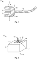
- Fig. 1 shows a first embodiment of an electrical structural member 1.
- the electrical structural member 1 in the form of a plug comprises an injection moulded workpiece 3 in which two contact elements 6 for producing an electrical contact with a mating plug which is not shown are arranged. Electrical currents are fed through a cable 10.
- the injection moulded workpiece 3 is surrounded in one part 140 by an electromagnetic shielding 2.
- the electromagnetic shielding 2 is formed by an electrically conductive coating on the injection moulded workpiece 3.
- the electromagnetic shielding 2 is located on an outer side 15 of the injection moulded workpiece 3. Together with a corresponding shielding on the mating plug, an inner space 70 is shielded.
- the electrically conductive coating 20 can be connected to a shielding element of the cable 10 via a connecting element which is not shown, for example in order to set the electrically conductive coating at ground potential.
- FIG. 2 a second embodiment of an electrical structural member 1 is shown, in which an electromagnetic shielding 2, which is formed by an electrically conductive coating 20, covers almost the entire outer side 15 of the electrical structural member 1 or of the injection moulded workpiece 3.
- a gap is only present in the region of an opening 8 on the upper side 11. This gap serves to emit electromagnetic radiation 13 by means of an antenna 7.
- Such a configuration can be achieved, for example, by a second component 32 which cannot be coated being used in the region of the antenna 7.
- a first component 31 is used which can be coated and which is covered by the electrically conductive coating 20.
- the injection moulded workpiece 3 illustrated in Fig. 3A consists of a first component 31 and a second component 32.
- the first component 31 comprises a material which can be coated
- the second component 32 consists of a material which cannot be coated.
- a part 130 which is to be coated is part of the first component 31.
- Electrical elements, which can be part of the electrical structural member 1, are not illustrated for the sake of simplicity, but can be located at different points on or in the injection moulded workpiece or can be covered or supported by it.
- the injection moulded workpiece 3 is at least partially immersed in a solution 50 which is located in a container 51.
- a solution 50 which is located in a container 51.
- an electrically conductive coating is deposited on the component 31.
- the second component 30 remains uncoated.
- Fig. 3C the fabricated injection moulded workpiece 3 is shown with a partial coating 20 in a part 140 on the first component 31 of the injection moulded workpiece 3.
- Fig. 4 shows a detail of a cross-section through a fifth embodiment.
- An injection moulded workpiece 3 has an electromagnetic shielding 2 which consists of two electrically conductive layers 21. These two layers 21 can have different thicknesses and/or consist of different materials. In particular, they can comprise metals.
- a layer 21, located further on the inside can be an adhesive agent between the plastic of the injection moulded workpiece 3 and a layer 21 located further on the outside.
- the layer 21 located further on the outside can achieve a better shielding effect than the layer 21 located further on the inside, but cannot be attached to the plastic without it.
- This protective coat 12 can consist of an insulating material such as plastic or a metal oxide.
- the injection moulded workpiece 3 again consists of a first component 31 and a second component 32.
- the first component 31 comprises an activatable material 104, in other words a material which becomes able to be coated with the electrically conductive coating by means of activation.
- the second component 32 does not have to be able to be coated nor be activatable.
- a part of the first component 31, i.e. a part 130 which is to be coated or an activation region 40, is activated by an activation radiation 41.
- the first component 31 therefore has become able to be coated, whereas it remains unable to be coated in the other region.
- Fig. 5C which again comprises the at least partial immersion of the injection moulded workpiece 3 in a solution 50 in a container 51, only the activation region 40 is coated with the electrically conductive coating 20.
- Fig. 5D A large part of the electrical structural member 1 is uncoated and only a small part 140 comprises an electromagnetic shielding 2 in the form of the electrically conductive coating 20.
- the structural member 1 can of course also be completely immersed in the solution.
- the electrical structural member 1 comprises a support 81 on which electrical elements 80 such as resistors, processors or the like can be arranged.
- Two shielding elements 60 form an inner space 70 in which the support 81 and the electrical elements 80 are arranged.
- the shielding elements 60 each have an electromagnetic shielding 2 in the form of an electrically conductive coating 20.
- the coatings 20 together form a shielding 90, which is closed on all sides, for the structural member 1 which neither allows electromagnetic radiation to pass through from the outside inwardly nor vice versa.
- the injection moulded workpiece 3 which in this case consists of only one single component 31 which is activatable, is activated by rays 42 made from an activation material 44 in the region of a hole 43 in a mask 49.
- the activation region 40 on the injection moulded workpiece 3 is defined by the hole 43. This therefore is a selective activation in the activation region 40 by means of the mask 49.
- the mask 49 is removed and the activation material 44 is optionally washed off in the activation region 40, as shown in Fig. 7B , the workpiece 3 is exposed to a gas atmosphere 27 which results in the workpiece 3 being coated in the activation region 40, as can be seen in Fig. 7C .
- coating can also be carried out in a selective manner, e.g. by applying a material through a mask 49.
- a selective application in the manner of an ink jet printer is also possible, both for an activation step and for a coating step.
Landscapes
- Engineering & Computer Science (AREA)
- Manufacturing & Machinery (AREA)
- Microelectronics & Electronic Packaging (AREA)
- Mechanical Engineering (AREA)
- Physics & Mathematics (AREA)
- Electromagnetism (AREA)
- Shielding Devices Or Components To Electric Or Magnetic Fields (AREA)
- Injection Moulding Of Plastics Or The Like (AREA)
Abstract
Description
- The invention relates to an electrical structural member with an electromagnetic shielding, and a method of producing an electrical structural member with an electromagnetic shielding.
- Structural members of this type often comprise an injection moulded workpiece, around which a specifically shaped metal sheet is attached for electromagnetic shielding from interference radiation, for example.
- However, such a procedure is complex.
- The problem of the invention is to provide a solution which allows for a simpler production and at the same time sufficient shielding.
- This is solved according to the invention in that the electromagnetic shielding is formed at least in sections by an electrically conductive coating of the injection moulded workpiece.
- In a method according to the invention, an electrically conductive coating is applied on at least a part of an injection moulded workpiece.
- By means of the solution according to the invention, the manufacturing and attachment of specifically shaped metal sheets can be dispensed with.
- The invention can be further improved by the following advantageous further developments, which can be combined freely, and advantageous configurations.
- The injection moulded workpiece can comprise a first component made from a first material and a second component made from a second material, wherein the first component is at least partially coated with an electrically conductive coating. Such a configuration enables a targeted coating in certain regions, for example if only certain parts are intended to be or allowed to be shielded.
- In a method according to the invention, a first component made from a first material and a second component made from a second material can therefore be used for the production, wherein the first component or the first material can be coated with metal.
- The second component can be uncoated. As a result, on the one hand a method step can be saved. On the other hand, it may be necessary that certain parts are not surrounded by a shielding, for example because radiation-emitting parts such as antennas are involved.
- In a corresponding method, only the first component is at least partially coated, while the second component is not coated.
- In a further advantageous configuration, the electrical structural member can comprise more than one injection moulded workpiece, wherein only one injection moulded workpiece is already coated or is being coated at least in sections.
- Advantageously, at least a part and/or a component of the injection moulded workpiece comprises an activatable material which can be activated for applying an electrically conductive coating. An electrically conductive coat, for example made from metal, can be applied in an activated state, whereas such an application is not possible in a non-activated state.
- In a corresponding method, an activatable material can therefore be used for a part or a component of the injection moulded piece.
- In a subsequent step, a part which is to be coated can be activated before the electrically conductive coating is applied. An activator can be applied. This can be, for example, an adhesive agent which enables the electrically conductive coating to adhere to the injection moulded workpiece. The activator can remain on the injection moulded workpiece. Alternatively, an activator can be removed before coating in the coating step.
- In the activation step, alternatively electromagnetic rays, for example, can be employed. These can for example alter the surface, e.g. oxidise, reduce or break bonds.
- The part of the electrical structural member and/or of the injection moulded workpiece which is to be coated can be selectively activated. A geometric selection can take place, for example, by using a mask which has openings at parts which are to be coated and which covers the injection moulded workpiece at parts which are not to be coated. When using radiation, it can be specifically directed at parts which are to be coated.
- Various possibilities are conceivable for carrying out the coating. For example, the injection moulded workpiece can be exposed to a liquid or a gas, for example by spraying, brushing, immersing or by a physical or chemical vapour deposition. If only one part of the injection moulded workpiece or only one component can be coated or is in an active state, only this part is coated. The injection moulded workpiece can also be subjected in its entirety to the coating process and does not have to be selectively coated. For example, the entire injection moulded workpiece can be immersed in a liquid. Non-activated parts and parts which cannot be coated are then not coated.
- In an alternative configuration, the injection moulded workpiece can be selectively coated, for example once again via a geometric selection, e.g. with masks, or by a directed coating, e.g. with a directed ray, for example in the manner of an ink jet printer. This can enable a more precise selection of the region which is to be coated.
- The injection moulded workpiece can comprise at least two components, wherein one component comprises an activatable material. The material or the component can be partially or fully activated in the finished state.
- In order to achieve a complete shielding, the coating can form a shielding, which is closed on all sides, for the structural member. However, it can also have smaller holes or gaps which should, however, be smaller than 10% of the wavelength of a radiation which is to be shielded, for example.
- In order to achieve a current flow and good shielding, different parts can be electrically conductively connected to each other.
- In an advantageous configuration, the coating together with a further electrical shielding on the same or on a different structural member forms a shielding which is closed on all sides. For example, a complete shielding may only be achieved by a plug being mated together with a mating plug. The shieldings can each be incomplete in a non-mated state.
- The electrically conductive coating can have at least two layers. The two layers can consist of different materials, for example in order to achieve a certain resistance in a targeted manner.
- In order to achieve a good shielding effect, the electromagnetic shielding or the electrically conductive coating can be present on an outer side of the structural member or of the injection moulded workpiece.
- In order to protect the coat, further coats can be present on top of the electrically conductive coating, which offer mechanical or chemical protection. These can be electrically insulating and made, for example, from an oxide or a plastic.
- In order to achieve a good shielding, the electrically conductive coat can comprise in particular a metal.
- The electromagnetic shielding or the electrically conductive coating can surround an inner space for receiving electrical structural members.
- The structural member can in particular be a connector or a plug, or a structural member in which electrical conductors of otherwise shielded cables are connected. By means of the electromagnetic shielding, shielding is achieved also in the region of the connection.
- The injection moulded workpiece can be a housing or a terminal block. By means of the solution according to the invention, further parts are saved here.
- The injection moulded workpiece can comprise a plastic. This can be easily reshaped.
- In order to achieve sufficient shielding, the electrically conductive coating can have a thickness of between 1 and 500 µm.
- The injection moulded workpiece can be an extra shield part. In such a configuration, a metal sheet which has been produced previously can be replaced by a coated shield part such that the production is easier and more economical.
- Hereinafter, the invention is explained in greater detail by way of example using advantageous configurations with reference to the drawings. The advantageous further developments and configurations illustrated in this instance are each independent of each other and can be freely combined with each other, depending on how this is necessary in the case of application.
- In the drawings:
-
Fig. 1 shows a schematic cross-sectional view of a first embodiment of an electrical structural member; -
Fig. 2 shows a schematic perspective view of a second embodiment of an electrical structural member; -
Figs. 3A, 3B, 3C show three steps in the production of a third embodiment of an electrical structural member; -
Fig. 4 shows a schematic sectional view of a fourth embodiment in a detail view; -
Figs. 5A, 5B, 5C, 5D show steps of a method of producing an embodiment of an electrical structural member; -
Fig. 6 shows a schematic sectional view of a sixth embodiment of an electrical structural member; -
Fig. 7A, 7B, 7C shows three steps of a method of producing a seventh embodiment of an electrical structural member. -
Fig. 1 shows a first embodiment of an electricalstructural member 1. The electricalstructural member 1 in the form of a plug comprises an injection mouldedworkpiece 3 in which twocontact elements 6 for producing an electrical contact with a mating plug which is not shown are arranged. Electrical currents are fed through acable 10. - In order to shield the connection region between the plug and the mating plug from electromagnetic radiation, for example, the injection moulded
workpiece 3 is surrounded in onepart 140 by anelectromagnetic shielding 2. In the shown exemplary embodiment, theelectromagnetic shielding 2 is formed by an electrically conductive coating on the injection mouldedworkpiece 3. - The
electromagnetic shielding 2 is located on anouter side 15 of the injection mouldedworkpiece 3. Together with a corresponding shielding on the mating plug, aninner space 70 is shielded. - The electrically
conductive coating 20 can be connected to a shielding element of thecable 10 via a connecting element which is not shown, for example in order to set the electrically conductive coating at ground potential. - In
Fig. 2 , a second embodiment of an electricalstructural member 1 is shown, in which anelectromagnetic shielding 2, which is formed by an electricallyconductive coating 20, covers almost the entireouter side 15 of the electricalstructural member 1 or of the injection mouldedworkpiece 3. A gap is only present in the region of anopening 8 on theupper side 11. This gap serves to emitelectromagnetic radiation 13 by means of anantenna 7. Such a configuration can be achieved, for example, by asecond component 32 which cannot be coated being used in the region of theantenna 7. In the other regions, afirst component 31 is used which can be coated and which is covered by the electricallyconductive coating 20. - In
Figures 3A, 3B, 3C , three steps of a method are shown with which an injection mouldedworkpiece 3 is at least partially coated with an electricallyconductive coating 20. - The injection moulded
workpiece 3 illustrated inFig. 3A consists of afirst component 31 and asecond component 32. Thefirst component 31 comprises a material which can be coated, whereas thesecond component 32 consists of a material which cannot be coated. Apart 130 which is to be coated is part of thefirst component 31. Electrical elements, which can be part of the electricalstructural member 1, are not illustrated for the sake of simplicity, but can be located at different points on or in the injection moulded workpiece or can be covered or supported by it. - In the method step illustrated in
Fig. 3B , the injection mouldedworkpiece 3 is at least partially immersed in asolution 50 which is located in acontainer 51. As a result, an electrically conductive coating is deposited on thecomponent 31. By contrast, the second component 30 remains uncoated. - In
Fig. 3C , the fabricated injection mouldedworkpiece 3 is shown with apartial coating 20 in apart 140 on thefirst component 31 of the injection mouldedworkpiece 3. -
Fig. 4 shows a detail of a cross-section through a fifth embodiment. An injection mouldedworkpiece 3 has anelectromagnetic shielding 2 which consists of two electricallyconductive layers 21. These twolayers 21 can have different thicknesses and/or consist of different materials. In particular, they can comprise metals. The injection mouldedworkpiece 3, in turn, preferably consists of a plastic. - A
layer 21, located further on the inside, can be an adhesive agent between the plastic of the injection mouldedworkpiece 3 and alayer 21 located further on the outside. Thelayer 21 located further on the outside can achieve a better shielding effect than thelayer 21 located further on the inside, but cannot be attached to the plastic without it. - Outside the two electrically
conductive layers 21 or the electricallyconductive coating 20, anotherprotective coat 12 is present which protects the twolayers 21, for example, from mechanical or chemical external influences. Thisprotective coat 12 can consist of an insulating material such as plastic or a metal oxide. - In
Figures 5A, 5B, 5C and 5D , different steps of a method of producing a fifth embodiment of an electricalstructural member 1 are shown. - As illustrated in
Fig. 5 , the injection mouldedworkpiece 3 again consists of afirst component 31 and asecond component 32. Thefirst component 31 comprises anactivatable material 104, in other words a material which becomes able to be coated with the electrically conductive coating by means of activation. Thesecond component 32 does not have to be able to be coated nor be activatable. A part of thefirst component 31, i.e. apart 130 which is to be coated or anactivation region 40, is activated by anactivation radiation 41. In theactivation region 40 shown inFig. 5B , thefirst component 31 therefore has become able to be coated, whereas it remains unable to be coated in the other region. - In the coating step shown in
Fig. 5C , which again comprises the at least partial immersion of the injection mouldedworkpiece 3 in asolution 50 in acontainer 51, only theactivation region 40 is coated with the electricallyconductive coating 20. The result can be seen inFig. 5D . A large part of the electricalstructural member 1 is uncoated and only asmall part 140 comprises anelectromagnetic shielding 2 in the form of the electricallyconductive coating 20. - In the procedure shown, the
structural member 1 can of course also be completely immersed in the solution. - In
Fig. 6 , a sixth embodiment is shown. The electricalstructural member 1 comprises asupport 81 on whichelectrical elements 80 such as resistors, processors or the like can be arranged. - Two shielding
elements 60 form aninner space 70 in which thesupport 81 and theelectrical elements 80 are arranged. The shieldingelements 60 each have anelectromagnetic shielding 2 in the form of an electricallyconductive coating 20. Thecoatings 20 together form a shielding 90, which is closed on all sides, for thestructural member 1 which neither allows electromagnetic radiation to pass through from the outside inwardly nor vice versa. - In
Figures 7A, 7B, 7C , a method of producing a seventh embodiment of an electricalstructural member 1 with anelectromagnetic shielding 2 is shown. - In the method step shown in
Fig. 7A , the injection mouldedworkpiece 3, which in this case consists of only onesingle component 31 which is activatable, is activated byrays 42 made from anactivation material 44 in the region of ahole 43 in amask 49. Theactivation region 40 on the injection mouldedworkpiece 3 is defined by thehole 43. This therefore is a selective activation in theactivation region 40 by means of themask 49. - After the
mask 49 is removed and theactivation material 44 is optionally washed off in theactivation region 40, as shown inFig. 7B , theworkpiece 3 is exposed to agas atmosphere 27 which results in theworkpiece 3 being coated in theactivation region 40, as can be seen inFig. 7C . - Similarly to the method shown in
Figures 7A, 7B and 7C , coating can also be carried out in a selective manner, e.g. by applying a material through amask 49. A selective application in the manner of an ink jet printer is also possible, both for an activation step and for a coating step. - Alternatively to the shown coating steps, other methods can also be used, for example brushing with a liquid, gel-like or paste-like material.
-
- 1
- Electrical structural member
- 2
- Electromagnetic shielding
- 3
- Injection moulded workpiece
- 6
- Contact element
- 7
- Antenna
- 8
- Opening
- 10
- Cable
- 11
- Upper side
- 12
- Protective coat
- 13
- Radiation
- 15
- Outer side
- 20
- Electrically conductive coating
- 21
- Electrically conductive layer
- 27
- Gas atmosphere
- 31
- First component
- 32
- Second component
- 40
- Activation region
- 41
- Activation radiation
- 42
- Rays
- 43
- Hole
- 44
- Activation material
- 49
- Mask
- 50
- Solution
- 51
- Container
- 60
- Shielding element
- 70
- Inner space
- 80
- Electrical elements
- 81
- Support
- 90
- Shielding closed on all sides
- 104
- Activatable material
- 130
- Part to be coated
- 140
- Part
Claims (13)
- An electrical structural member (1) with an electromagnetic shielding (2), wherein the structural member (1) comprises an injection moulded workpiece (3), characterised in that the electromagnetic shielding (2) is formed at least in sections by an electrically conductive coating (20) of the injection moulded workpiece (3).
- The electrical structural member (1) according to Claim 1, wherein the injection moulded workpiece (3) comprises a first component (31) made from a first material and a second component (32) made from a second material, and the first component (31) is at least partially coated with an electrically conductive coating (20).
- The electrical structural member (1) according to Claim 2, wherein the second component (32) is uncoated.
- The electrical structural member (1) according to any one of Claims 1 to 3, wherein at least a part (140) of the injection moulded workpiece (3) comprises an activatable material (104) which can be activated for applying an electrically conductive coating (20).
- The electrical structural member (1) according to any one of Claims 1 to 4, wherein the injection moulded workpiece (3) comprises at least two components (31, 32) and at least a component (31) comprises an activatable material (104).
- The electrical structural member (1) according to any one of Claims 1 to 5, wherein the electrically conductive coating (20) forms a shielding (90), which is closed on all sides, for the structural member (1).
- The electrical structural member (1) according to any one of Claims 1 to 6, wherein the electrically conductive coating (20) comprises at least two electrically conductive layers (21).
- A method of producing an electrical structural member (1) with an electromagnetic shielding (2), wherein the structural member (1) comprises an injection moulded workpiece (3), characterised in that it comprises a step in which an electrically conductive coating (20) is applied on at least a part (140) of an injection moulded workpiece.
- The method according to Claim 8, wherein the part (130) which is to be coated is activated for applying an electrically conductive coating (20) before the electrically conductive coating (20) is applied.
- The method according to one of Claims 8 or 9, wherein the part (130) of the structural member (1) which is to be coated is selectively activated.
- The method according to any one of Claims 8 to 10, wherein the part (140) of the structural member (1) is selectively coated.
- The method according to any one of Claims 8 to 11, wherein the entire injection moulded workpiece (3) undergoes an activation step.
- The method according to any one of Claims 8 to 12, wherein the activation step and/or the coating step comprises an immersion in a liquid (50), at least in sections.
Applications Claiming Priority (1)
| Application Number | Priority Date | Filing Date | Title |
|---|---|---|---|
| DE102017201616.7A DE102017201616A1 (en) | 2017-02-01 | 2017-02-01 | Electromagnetic shielded electrical component, method of making an electrical component with electromagnetic shielding |
Publications (1)
| Publication Number | Publication Date |
|---|---|
| EP3357662A1 true EP3357662A1 (en) | 2018-08-08 |
Family
ID=61131987
Family Applications (1)
| Application Number | Title | Priority Date | Filing Date |
|---|---|---|---|
| EP18153560.0A Withdrawn EP3357662A1 (en) | 2017-02-01 | 2018-01-26 | Electrical structural member with an electromagnetic shielding, method of producing an electrical structural member with an electromagnetic shielding |
Country Status (5)
| Country | Link |
|---|---|
| US (1) | US10426066B2 (en) |
| EP (1) | EP3357662A1 (en) |
| JP (1) | JP2018125531A (en) |
| CN (1) | CN108377636A (en) |
| DE (1) | DE102017201616A1 (en) |
Families Citing this family (2)
| Publication number | Priority date | Publication date | Assignee | Title |
|---|---|---|---|---|
| TW202026798A (en) | 2019-01-11 | 2020-07-16 | 和碩聯合科技股份有限公司 | Connector |
| DE102022130663A1 (en) * | 2022-11-21 | 2024-05-23 | Elringklinger Ag | Protective element, component set and method for producing the protective element |
Citations (4)
| Publication number | Priority date | Publication date | Assignee | Title |
|---|---|---|---|---|
| US20040079645A1 (en) * | 2002-10-24 | 2004-04-29 | Chang-Huang Chiu | Method for manufacturing personal digital assistant |
| US20050277340A1 (en) * | 2004-06-10 | 2005-12-15 | Gordon W A | Modular plug assemblies, terminated cable assemblies and methods for forming the same |
| US20090239079A1 (en) * | 2008-03-18 | 2009-09-24 | Mark Wojtaszek | Process for Preventing Plating on a Portion of a Molded Plastic Part |
| US20150077961A1 (en) * | 2013-01-28 | 2015-03-19 | BT Engineering | Controlled impedance pcb encapsulation |
Family Cites Families (3)
| Publication number | Priority date | Publication date | Assignee | Title |
|---|---|---|---|---|
| US5170009A (en) * | 1990-03-22 | 1992-12-08 | Canon Kabushiki Kaisha | Electrically conductive covers and electrically conductive covers of electronic equipment |
| US8822844B1 (en) * | 2010-09-27 | 2014-09-02 | Rockwell Collins, Inc. | Shielding and potting for electrical circuits |
| DE102012001926A1 (en) * | 2012-02-02 | 2013-08-08 | Benteler Automobiltechnik Gmbh | Fuel rail |
-
2017
- 2017-02-01 DE DE102017201616.7A patent/DE102017201616A1/en not_active Withdrawn
-
2018
- 2018-01-26 JP JP2018011403A patent/JP2018125531A/en active Pending
- 2018-01-26 EP EP18153560.0A patent/EP3357662A1/en not_active Withdrawn
- 2018-02-01 CN CN201810102625.7A patent/CN108377636A/en active Pending
- 2018-02-01 US US15/885,899 patent/US10426066B2/en not_active Expired - Fee Related
Patent Citations (4)
| Publication number | Priority date | Publication date | Assignee | Title |
|---|---|---|---|---|
| US20040079645A1 (en) * | 2002-10-24 | 2004-04-29 | Chang-Huang Chiu | Method for manufacturing personal digital assistant |
| US20050277340A1 (en) * | 2004-06-10 | 2005-12-15 | Gordon W A | Modular plug assemblies, terminated cable assemblies and methods for forming the same |
| US20090239079A1 (en) * | 2008-03-18 | 2009-09-24 | Mark Wojtaszek | Process for Preventing Plating on a Portion of a Molded Plastic Part |
| US20150077961A1 (en) * | 2013-01-28 | 2015-03-19 | BT Engineering | Controlled impedance pcb encapsulation |
Non-Patent Citations (1)
| Title |
|---|
| ANONYMOUS: "Plasma (Physik) - Wikipedia", 23 December 2016 (2016-12-23), XP055670686, Retrieved from the Internet <URL:https://de.wikipedia.org/w/index.php?title=Plasma_(Physik)&oldid=160913856> [retrieved on 20200220] * |
Also Published As
| Publication number | Publication date |
|---|---|
| DE102017201616A1 (en) | 2018-08-02 |
| CN108377636A (en) | 2018-08-07 |
| JP2018125531A (en) | 2018-08-09 |
| US10426066B2 (en) | 2019-09-24 |
| US20180220557A1 (en) | 2018-08-02 |
Similar Documents
| Publication | Publication Date | Title |
|---|---|---|
| US10879005B2 (en) | Electronic component and method of manufacturing same | |
| US8764484B2 (en) | Electrical connector with multilayer surface treatment and method for fabricating the same | |
| JP6138265B2 (en) | Insulator with shield cloth | |
| US20150140202A1 (en) | Aluminum Electrical Wire with Crimped Terminal and Method for Producing Aluminum Electrical Wire with Crimped Terminal | |
| US9426936B2 (en) | Systems for assembling electronic devices with internal moisture-resistant coatings | |
| DE112018002672T5 (en) | MICROPHONE HOUSING FOR FULL-COVERED ASIC AND WIRES | |
| JP5946531B2 (en) | Insulator with cross-shaped shield | |
| KR20140027472A (en) | Shielding for cable components and method | |
| JP6468294B2 (en) | Enclosure for electric element and method of manufacturing enclosure for electric element | |
| US10468789B2 (en) | Electrical connector with a sleeve having an electrical device | |
| US10426066B2 (en) | Electrical member with an electromagnetic shielding, method of producing an electrical member with an electromagnetic shielding | |
| JP2015176887A (en) | Electromagnetic shield member and wire harness | |
| US9929518B2 (en) | Assembled electrical cable | |
| US10777912B2 (en) | Electrical contact element and method for altering mechanical and/or electrical properties of at least one area of such | |
| JP5915265B2 (en) | Electronic component and method for manufacturing electronic component | |
| JP6394777B2 (en) | Electromagnetic shield member, wire harness, and method of manufacturing electromagnetic shield member | |
| EP4622008A1 (en) | Coaxial contact system and method for electrically connecting two outer conductors | |
| JP2002359017A (en) | Wire connection structure and method of bleeding air from inside device case | |
| CN113395824B (en) | Flexible circuit board and preparation method thereof | |
| CN115211239A (en) | Method for manufacturing an electrical device | |
| US10903159B2 (en) | Electrical cable | |
| JP2015170434A (en) | Electromagnetic shield member and wire harness | |
| JP3121073U (en) | Covered conductive wire | |
| CN103247852A (en) | Metal cap with antenna function and manufacturing method of metal cap |
Legal Events
| Date | Code | Title | Description |
|---|---|---|---|
| PUAI | Public reference made under article 153(3) epc to a published international application that has entered the european phase |
Free format text: ORIGINAL CODE: 0009012 |
|
| STAA | Information on the status of an ep patent application or granted ep patent |
Free format text: STATUS: THE APPLICATION HAS BEEN PUBLISHED |
|
| AK | Designated contracting states |
Kind code of ref document: A1 Designated state(s): AL AT BE BG CH CY CZ DE DK EE ES FI FR GB GR HR HU IE IS IT LI LT LU LV MC MK MT NL NO PL PT RO RS SE SI SK SM TR |
|
| AX | Request for extension of the european patent |
Extension state: BA ME |
|
| STAA | Information on the status of an ep patent application or granted ep patent |
Free format text: STATUS: REQUEST FOR EXAMINATION WAS MADE |
|
| 17P | Request for examination filed |
Effective date: 20190207 |
|
| RBV | Designated contracting states (corrected) |
Designated state(s): AL AT BE BG CH CY CZ DE DK EE ES FI FR GB GR HR HU IE IS IT LI LT LU LV MC MK MT NL NO PL PT RO RS SE SI SK SM TR |
|
| STAA | Information on the status of an ep patent application or granted ep patent |
Free format text: STATUS: EXAMINATION IS IN PROGRESS |
|
| 17Q | First examination report despatched |
Effective date: 20190517 |
|
| STAA | Information on the status of an ep patent application or granted ep patent |
Free format text: STATUS: THE APPLICATION IS DEEMED TO BE WITHDRAWN |
|
| 18D | Application deemed to be withdrawn |
Effective date: 20200708 |