EP3357630B1 - Verfahren und vorrichtung zum reparieren einer beschädigten schaufelspitze einer gepanzerten und mit einer schaufelbeschichtung versehenen turbinenschaufel - Google Patents
Verfahren und vorrichtung zum reparieren einer beschädigten schaufelspitze einer gepanzerten und mit einer schaufelbeschichtung versehenen turbinenschaufel Download PDFInfo
- Publication number
- EP3357630B1 EP3357630B1 EP18153785.3A EP18153785A EP3357630B1 EP 3357630 B1 EP3357630 B1 EP 3357630B1 EP 18153785 A EP18153785 A EP 18153785A EP 3357630 B1 EP3357630 B1 EP 3357630B1
- Authority
- EP
- European Patent Office
- Prior art keywords
- blade
- blade tip
- repair
- coating
- turbine
- Prior art date
- Legal status (The legal status is an assumption and is not a legal conclusion. Google has not performed a legal analysis and makes no representation as to the accuracy of the status listed.)
- Active
Links
Images
Classifications
-
- F—MECHANICAL ENGINEERING; LIGHTING; HEATING; WEAPONS; BLASTING
- F01—MACHINES OR ENGINES IN GENERAL; ENGINE PLANTS IN GENERAL; STEAM ENGINES
- F01D—NON-POSITIVE DISPLACEMENT MACHINES OR ENGINES, e.g. STEAM TURBINES
- F01D5/00—Blades; Blade-carrying members; Heating, heat-insulating, cooling or antivibration means on the blades or the members
- F01D5/005—Repairing methods or devices
-
- B—PERFORMING OPERATIONS; TRANSPORTING
- B23—MACHINE TOOLS; METAL-WORKING NOT OTHERWISE PROVIDED FOR
- B23K—SOLDERING OR UNSOLDERING; WELDING; CLADDING OR PLATING BY SOLDERING OR WELDING; CUTTING BY APPLYING HEAT LOCALLY, e.g. FLAME CUTTING; WORKING BY LASER BEAM
- B23K10/00—Welding or cutting by means of a plasma
- B23K10/02—Plasma welding
- B23K10/027—Welding for purposes other than joining, e.g. build-up welding
-
- B—PERFORMING OPERATIONS; TRANSPORTING
- B23—MACHINE TOOLS; METAL-WORKING NOT OTHERWISE PROVIDED FOR
- B23K—SOLDERING OR UNSOLDERING; WELDING; CLADDING OR PLATING BY SOLDERING OR WELDING; CUTTING BY APPLYING HEAT LOCALLY, e.g. FLAME CUTTING; WORKING BY LASER BEAM
- B23K15/00—Electron-beam welding or cutting
- B23K15/0046—Welding
- B23K15/0086—Welding welding for purposes other than joining, e.g. build-up welding
-
- B—PERFORMING OPERATIONS; TRANSPORTING
- B23—MACHINE TOOLS; METAL-WORKING NOT OTHERWISE PROVIDED FOR
- B23K—SOLDERING OR UNSOLDERING; WELDING; CLADDING OR PLATING BY SOLDERING OR WELDING; CUTTING BY APPLYING HEAT LOCALLY, e.g. FLAME CUTTING; WORKING BY LASER BEAM
- B23K15/00—Electron-beam welding or cutting
- B23K15/0046—Welding
- B23K15/0093—Welding characterised by the properties of the materials to be welded
-
- B—PERFORMING OPERATIONS; TRANSPORTING
- B23—MACHINE TOOLS; METAL-WORKING NOT OTHERWISE PROVIDED FOR
- B23K—SOLDERING OR UNSOLDERING; WELDING; CLADDING OR PLATING BY SOLDERING OR WELDING; CUTTING BY APPLYING HEAT LOCALLY, e.g. FLAME CUTTING; WORKING BY LASER BEAM
- B23K26/00—Working by laser beam, e.g. welding, cutting or boring
- B23K26/0006—Working by laser beam, e.g. welding, cutting or boring taking account of the properties of the material involved
-
- B—PERFORMING OPERATIONS; TRANSPORTING
- B23—MACHINE TOOLS; METAL-WORKING NOT OTHERWISE PROVIDED FOR
- B23K—SOLDERING OR UNSOLDERING; WELDING; CLADDING OR PLATING BY SOLDERING OR WELDING; CUTTING BY APPLYING HEAT LOCALLY, e.g. FLAME CUTTING; WORKING BY LASER BEAM
- B23K26/00—Working by laser beam, e.g. welding, cutting or boring
- B23K26/34—Laser welding for purposes other than joining
-
- B—PERFORMING OPERATIONS; TRANSPORTING
- B23—MACHINE TOOLS; METAL-WORKING NOT OTHERWISE PROVIDED FOR
- B23K—SOLDERING OR UNSOLDERING; WELDING; CLADDING OR PLATING BY SOLDERING OR WELDING; CUTTING BY APPLYING HEAT LOCALLY, e.g. FLAME CUTTING; WORKING BY LASER BEAM
- B23K31/00—Processes relevant to this subclass, specially adapted for particular articles or purposes, but not covered by any single one of main groups B23K1/00 - B23K28/00
- B23K31/02—Processes relevant to this subclass, specially adapted for particular articles or purposes, but not covered by any single one of main groups B23K1/00 - B23K28/00 relating to soldering or welding
-
- B—PERFORMING OPERATIONS; TRANSPORTING
- B23—MACHINE TOOLS; METAL-WORKING NOT OTHERWISE PROVIDED FOR
- B23K—SOLDERING OR UNSOLDERING; WELDING; CLADDING OR PLATING BY SOLDERING OR WELDING; CUTTING BY APPLYING HEAT LOCALLY, e.g. FLAME CUTTING; WORKING BY LASER BEAM
- B23K31/00—Processes relevant to this subclass, specially adapted for particular articles or purposes, but not covered by any single one of main groups B23K1/00 - B23K28/00
- B23K31/10—Processes relevant to this subclass, specially adapted for particular articles or purposes, but not covered by any single one of main groups B23K1/00 - B23K28/00 relating to cutting or desurfacing
-
- B—PERFORMING OPERATIONS; TRANSPORTING
- B23—MACHINE TOOLS; METAL-WORKING NOT OTHERWISE PROVIDED FOR
- B23K—SOLDERING OR UNSOLDERING; WELDING; CLADDING OR PLATING BY SOLDERING OR WELDING; CUTTING BY APPLYING HEAT LOCALLY, e.g. FLAME CUTTING; WORKING BY LASER BEAM
- B23K9/00—Arc welding or cutting
- B23K9/04—Welding for other purposes than joining, e.g. built-up welding
-
- B—PERFORMING OPERATIONS; TRANSPORTING
- B23—MACHINE TOOLS; METAL-WORKING NOT OTHERWISE PROVIDED FOR
- B23P—METAL-WORKING NOT OTHERWISE PROVIDED FOR; COMBINED OPERATIONS; UNIVERSAL MACHINE TOOLS
- B23P6/00—Restoring or reconditioning objects
- B23P6/002—Repairing turbine components, e.g. moving or stationary blades, rotors
- B23P6/007—Repairing turbine components, e.g. moving or stationary blades, rotors using only additive methods, e.g. build-up welding
-
- F—MECHANICAL ENGINEERING; LIGHTING; HEATING; WEAPONS; BLASTING
- F01—MACHINES OR ENGINES IN GENERAL; ENGINE PLANTS IN GENERAL; STEAM ENGINES
- F01D—NON-POSITIVE DISPLACEMENT MACHINES OR ENGINES, e.g. STEAM TURBINES
- F01D11/00—Preventing or minimising internal leakage of working-fluid, e.g. between stages
- F01D11/08—Preventing or minimising internal leakage of working-fluid, e.g. between stages for sealing space between rotor blade tips and stator
- F01D11/12—Preventing or minimising internal leakage of working-fluid, e.g. between stages for sealing space between rotor blade tips and stator using a rubstrip, e.g. erodible. deformable or resiliently-biased part
- F01D11/122—Preventing or minimising internal leakage of working-fluid, e.g. between stages for sealing space between rotor blade tips and stator using a rubstrip, e.g. erodible. deformable or resiliently-biased part with erodable or abradable material
-
- B—PERFORMING OPERATIONS; TRANSPORTING
- B23—MACHINE TOOLS; METAL-WORKING NOT OTHERWISE PROVIDED FOR
- B23K—SOLDERING OR UNSOLDERING; WELDING; CLADDING OR PLATING BY SOLDERING OR WELDING; CUTTING BY APPLYING HEAT LOCALLY, e.g. FLAME CUTTING; WORKING BY LASER BEAM
- B23K2101/00—Articles made by soldering, welding or cutting
- B23K2101/001—Turbines
-
- F—MECHANICAL ENGINEERING; LIGHTING; HEATING; WEAPONS; BLASTING
- F01—MACHINES OR ENGINES IN GENERAL; ENGINE PLANTS IN GENERAL; STEAM ENGINES
- F01D—NON-POSITIVE DISPLACEMENT MACHINES OR ENGINES, e.g. STEAM TURBINES
- F01D5/00—Blades; Blade-carrying members; Heating, heat-insulating, cooling or antivibration means on the blades or the members
- F01D5/12—Blades
- F01D5/28—Selecting particular materials; Particular measures relating thereto; Measures against erosion or corrosion
- F01D5/288—Protective coatings for blades
-
- F—MECHANICAL ENGINEERING; LIGHTING; HEATING; WEAPONS; BLASTING
- F05—INDEXING SCHEMES RELATING TO ENGINES OR PUMPS IN VARIOUS SUBCLASSES OF CLASSES F01-F04
- F05D—INDEXING SCHEME FOR ASPECTS RELATING TO NON-POSITIVE-DISPLACEMENT MACHINES OR ENGINES, GAS-TURBINES OR JET-PROPULSION PLANTS
- F05D2220/00—Application
- F05D2220/30—Application in turbines
- F05D2220/32—Application in turbines in gas turbines
-
- F—MECHANICAL ENGINEERING; LIGHTING; HEATING; WEAPONS; BLASTING
- F05—INDEXING SCHEMES RELATING TO ENGINES OR PUMPS IN VARIOUS SUBCLASSES OF CLASSES F01-F04
- F05D—INDEXING SCHEME FOR ASPECTS RELATING TO NON-POSITIVE-DISPLACEMENT MACHINES OR ENGINES, GAS-TURBINES OR JET-PROPULSION PLANTS
- F05D2230/00—Manufacture
- F05D2230/20—Manufacture essentially without removing material
- F05D2230/23—Manufacture essentially without removing material by permanently joining parts together
- F05D2230/232—Manufacture essentially without removing material by permanently joining parts together by welding
- F05D2230/237—Brazing
-
- F—MECHANICAL ENGINEERING; LIGHTING; HEATING; WEAPONS; BLASTING
- F05—INDEXING SCHEMES RELATING TO ENGINES OR PUMPS IN VARIOUS SUBCLASSES OF CLASSES F01-F04
- F05D—INDEXING SCHEME FOR ASPECTS RELATING TO NON-POSITIVE-DISPLACEMENT MACHINES OR ENGINES, GAS-TURBINES OR JET-PROPULSION PLANTS
- F05D2230/00—Manufacture
- F05D2230/20—Manufacture essentially without removing material
- F05D2230/23—Manufacture essentially without removing material by permanently joining parts together
- F05D2230/232—Manufacture essentially without removing material by permanently joining parts together by welding
- F05D2230/238—Soldering
-
- F—MECHANICAL ENGINEERING; LIGHTING; HEATING; WEAPONS; BLASTING
- F05—INDEXING SCHEMES RELATING TO ENGINES OR PUMPS IN VARIOUS SUBCLASSES OF CLASSES F01-F04
- F05D—INDEXING SCHEME FOR ASPECTS RELATING TO NON-POSITIVE-DISPLACEMENT MACHINES OR ENGINES, GAS-TURBINES OR JET-PROPULSION PLANTS
- F05D2230/00—Manufacture
- F05D2230/30—Manufacture with deposition of material
- F05D2230/31—Layer deposition
-
- F—MECHANICAL ENGINEERING; LIGHTING; HEATING; WEAPONS; BLASTING
- F05—INDEXING SCHEMES RELATING TO ENGINES OR PUMPS IN VARIOUS SUBCLASSES OF CLASSES F01-F04
- F05D—INDEXING SCHEME FOR ASPECTS RELATING TO NON-POSITIVE-DISPLACEMENT MACHINES OR ENGINES, GAS-TURBINES OR JET-PROPULSION PLANTS
- F05D2230/00—Manufacture
- F05D2230/80—Repairing, retrofitting or upgrading methods
-
- F—MECHANICAL ENGINEERING; LIGHTING; HEATING; WEAPONS; BLASTING
- F05—INDEXING SCHEMES RELATING TO ENGINES OR PUMPS IN VARIOUS SUBCLASSES OF CLASSES F01-F04
- F05D—INDEXING SCHEME FOR ASPECTS RELATING TO NON-POSITIVE-DISPLACEMENT MACHINES OR ENGINES, GAS-TURBINES OR JET-PROPULSION PLANTS
- F05D2230/00—Manufacture
- F05D2230/90—Coating; Surface treatment
-
- F—MECHANICAL ENGINEERING; LIGHTING; HEATING; WEAPONS; BLASTING
- F05—INDEXING SCHEMES RELATING TO ENGINES OR PUMPS IN VARIOUS SUBCLASSES OF CLASSES F01-F04
- F05D—INDEXING SCHEME FOR ASPECTS RELATING TO NON-POSITIVE-DISPLACEMENT MACHINES OR ENGINES, GAS-TURBINES OR JET-PROPULSION PLANTS
- F05D2240/00—Components
- F05D2240/20—Rotors
- F05D2240/30—Characteristics of rotor blades, i.e. of any element transforming dynamic fluid energy to or from rotational energy and being attached to a rotor
- F05D2240/307—Characteristics of rotor blades, i.e. of any element transforming dynamic fluid energy to or from rotational energy and being attached to a rotor related to the tip of a rotor blade
-
- F—MECHANICAL ENGINEERING; LIGHTING; HEATING; WEAPONS; BLASTING
- F05—INDEXING SCHEMES RELATING TO ENGINES OR PUMPS IN VARIOUS SUBCLASSES OF CLASSES F01-F04
- F05D—INDEXING SCHEME FOR ASPECTS RELATING TO NON-POSITIVE-DISPLACEMENT MACHINES OR ENGINES, GAS-TURBINES OR JET-PROPULSION PLANTS
- F05D2300/00—Materials; Properties thereof
- F05D2300/20—Oxide or non-oxide ceramics
- F05D2300/22—Non-oxide ceramics
- F05D2300/228—Nitrides
- F05D2300/2282—Nitrides of boron
-
- F—MECHANICAL ENGINEERING; LIGHTING; HEATING; WEAPONS; BLASTING
- F05—INDEXING SCHEMES RELATING TO ENGINES OR PUMPS IN VARIOUS SUBCLASSES OF CLASSES F01-F04
- F05D—INDEXING SCHEME FOR ASPECTS RELATING TO NON-POSITIVE-DISPLACEMENT MACHINES OR ENGINES, GAS-TURBINES OR JET-PROPULSION PLANTS
- F05D2300/00—Materials; Properties thereof
- F05D2300/50—Intrinsic material properties or characteristics
- F05D2300/506—Hardness
Definitions
- the invention relates to a method for repairing a damaged blade tip of an armored turbine blade of a thermal gas turbine provided with a blade coating.
- the invention further relates to a device for carrying out such a method.
- Such a method and such a device are known from US 5 794 338 A known.
- Armored turbine blades with a blade coating can usually only be repaired a few times, as the material removed when the components are stripped leads to a loss of wall thickness and strength. Accordingly, such turbine blades often have to be scrapped after just a few cases of damage, as they have reached their maximum number of permissible strippings of the blade. This leads to high costs. Additional costs arise because the previous methods for component repair of armored turbine blades, especially HPT blades, include many expensive process steps.
- EP 1 143 030 A1 discloses a material for a turbine blade tip or for repairing a damaged turbine blade tip with a metallic coating. Also disclosed is a method for producing or repairing a turbine blade tip with a metallic coating by restoring the blade tip with a material that corresponds in composition to the metallic coating material used for the turbine blade by bonding the material to the damaged tip.
- the object of the present invention is to provide a method which enables more frequent and more cost-effective repairs of damaged blade tips of armored turbine blades and those provided with a blade coating.
- a further object of the invention is to provide a device for carrying out such a method.
- a first aspect of the invention relates to a method for repairing a damaged blade tip of an armored and blade-coated turbine blade of a thermal gas turbine.
- the method comprises the steps of removing a blade tip armor of the turbine blade at least in the area of the damaged blade tip and producing a repair surface, removing only part of the blade coating of the turbine blade in the area of the repair surface while retaining a part of the blade coating spaced apart from the repair surface, restoring the blade tip armor and restoring the blade coating in the area of the repaired blade tip, wherein in order to restore the blade tip armor, a repair material is applied to the repair surface by a welding process and/or by an additive manufacturing process.
- damaged blade tips of armored and coated turbine blades can be repaired quickly and reliably in a few, cost-effective steps.
- several steps and in particular the complete stripping and subsequent complete recoating of the turbine blade can be dispensed with, so that time and costs are saved to a considerable extent.
- the repair of the armored blade tip is not associated with a loss of wall thickness and strength of the blade, which significantly increases the number of possible repairs and thus the service life of the turbine blade, which leads to further significant time and cost savings.
- a further advantage is better running time behavior of the locally repaired turbine blade as a result of the comparatively gentle repair. Furthermore, it is possible to build up the original or target contour of the blade tip with little mixing and a small heat-affected zone, which reliably restores the original shape and load-bearing capacity of the turbine blade.
- "a"/"an” are to be read as indefinite articles in the context of this disclosure, i.e., unless expressly stated otherwise, always as “at least one"/"at least one".
- the repair material is applied to the repair surface and a target contour of the blade tip is restored. This allows the original geometry of the turbine blade to be completely restored.
- the blade tip armor and/or the blade coating is at least partially removed by means of a separation process.
- This allows the blade tip armor to be partially or completely removed depending on the respective damage pattern. Machining manufacturing processes such as grinding are particularly suitable as separation processes.
- the blade coating can also in the area of the blade tip by means of a separation process in order to prepare the turbine blade for the subsequent application of repair material.
- the repair material is applied to the repair surface by deposition welding. This makes it possible to build up the original or target contour of the blade tip with little mixing and a small heat-affected zone, which reliably restores the original shape and load-bearing capacity of the turbine blade.
- the original or target contour of the blade tip can be restored simply by the step of applying repair material in a targeted manner.
- the blade coating is only removed up to a distance of a maximum of 15%, i.e. a maximum of 1%, 2%, 3%, 4%, 5%, 6%, 7%, 8%, 9%, 10%, 11%, 12%, 13%, 14% or 15% of the height of the blade to the repair surface. This prevents an unnecessary loss of wall thickness and strength of the blade, which significantly increases the number of possible repairs and thus the service life of the turbine blade.
- the target contour of the blade tip is restored by means of a separation process after the repair material has been applied.
- a separation process is particularly advantageous if the repair material was initially applied with an excess in relation to the original or target contour of the blade tip and is then restored by removing excess repair material.
- machining processes such as grinding are particularly suitable as separation processes.
- the blade tip armor is restored using a joining process, in particular by soldering.
- This enables a material-locking and thus particularly high-strength connection between the blade tip of the turbine blade and the blade tip armor.
- the use of a soldering process can advantageously create a surface alloy between the blade or repair material. and the material of the blade tip armor without melting the turbine blade at depth.
- the blade tip armor is restored by producing and/or applying a particle composite material with embedded hard material particles, in particular made of cubic boron nitride (CBN), to the blade tip. This makes it possible to produce a blade tip armor that is particularly thermally, chemically and mechanically resistant.
- CBN cubic boron nitride
- hard material particles made of cubic boron nitride (CBN), which may also be coated with an active element, can be applied.
- the hard material particles can be embedded in an enclosing matrix, for example made of a solder material, which results in a particularly stable connection between the hard material particles and the blade tip.
- the particle composite material can be produced directly on the turbine blade or initially produced separately from it, applied to the turbine blade and connected to it.
- a second aspect of the invention relates to a device for carrying out a method according to the first aspect of the invention.
- the device comprises a first separating device which is designed to remove a blade tip armor of the turbine blade at least in the region of the damaged blade tip and to produce a repair surface, a first repair device which is designed to restore the blade tip armor, and a second repair device which is designed to restore the blade coating in the region of the repaired blade tip.
- the device additionally has a second separating device which is designed to remove only a part of the blade coating of the turbine blade in the region of the repair surface while retaining a part of the blade coating which is spaced apart from the repair surface, and a third repair device which is designed to apply a repair material by a welding process and/or by an additive manufacturing process to the repair surface and to restore a desired contour of the blade tip.
- a second separating device which is designed to remove only a part of the blade coating of the turbine blade in the region of the repair surface while retaining a part of the blade coating which is spaced apart from the repair surface
- a third repair device which is designed to apply a repair material by a welding process and/or by an additive manufacturing process to the repair surface and to restore a desired contour of the blade tip.
- the term "designed to" is generally understood to mean devices that not only have a basic suitability for the relevant action, but that are specifically set up on a hardware and/or software basis in such a way that they actually carry out the relevant action.
- the device can basically have a control device by means of which the individual separating and/or repair devices are to be controlled and/or regulated.
- the control device has a processor device that is set up to carry out an embodiment of the method according to the invention.
- the processor device can have at least one microprocessor and/or at least one microcontroller. Furthermore, the processor device can have program code that is set up to carry out the embodiment of the method according to the invention when executed by the processor device. The program code can be stored in a data memory of the processor device. Further features and their advantages can be found in the descriptions of the first aspect of the invention, wherein advantageous embodiments of the first aspect of the invention are to be regarded as advantageous embodiments of the second aspect of the invention and vice versa.
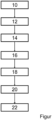
- FIG. 1 shows a flow chart of a method according to the invention for repairing a damaged blade tip of an armored turbine blade provided with a blade coating.
- the single figure shows a flow chart of a method according to the invention for repairing a damaged blade tip of an armored turbine blade provided with a blade coating, for example a high-pressure turbine blade (HPT blade).
- a blade coating for example a high-pressure turbine blade (HPT blade).
- the damaged turbine blade is provided and prepared for repair.
- the blade tip armor of the turbine blade is removed at least in the area of the damaged blade tip and a repair surface is produced. This can be done, for example, by machining such as grinding.
- the blade coating (airfoil coating) of the turbine blade is removed only in the area of the repair surface, retaining a part of the blade coating that is spaced apart from the repair surface, in order to prepare the turbine blade for subsequent welding (step 16).
- This step can also be done, for example, by machining.
- the repair method therefore dispenses with complete stripping. of the turbine blade and therefore does not lead to a loss of wall thickness and strength, especially of the blade which is subjected to high loads during operation. This means that the repair is much gentler on the component and can be carried out several times on the same turbine blade without any problems.
- step 16 repair material is applied to the repair surface by welding and, in a generally optional step 18, it is recontoured by machining (e.g. by grinding) in order to restore the original or target contour of the blade tip. If the desired contour of the blade tip has already been created in step 16, step 18 is not necessary. If the damage pattern in the individual case does not require reconstruction with repair material, step 16 can generally be omitted.
- the blade tip armor is then restored by a step that preferably also only acts locally on the turbine blade, e.g. by local soldering.
- the blade tip armor can be made, for example, from cubic boron nitride (CBN), which is embedded in a matrix.
- a locally limited "touch-up” diffusion coating is applied to restore the blade coating in the area of the repaired blade tip and thus protect the turbine blade against thermal and chemical influences.
- the proposed procedure eliminates several steps, in particular the complete stripping and subsequent recoating of the blade, thus saving time and money to a considerable extent.
- the turbine blade that has only been repaired locally also has an improved service life as a result of a gentle repair in conjunction with comparatively low repair costs.
Landscapes
- Engineering & Computer Science (AREA)
- Mechanical Engineering (AREA)
- Physics & Mathematics (AREA)
- Plasma & Fusion (AREA)
- Optics & Photonics (AREA)
- General Engineering & Computer Science (AREA)
- Chemical & Material Sciences (AREA)
- Materials Engineering (AREA)
- Turbine Rotor Nozzle Sealing (AREA)
Description
- Die Erfindung betrifft ein Verfahren zum Reparieren einer beschädigten Schaufelspitze einer gepanzerten und mit einer Schaufelbeschichtung versehenen Turbinenschaufel einer thermischen Gasturbine. Die Erfindung betrifft weiterhin eine Vorrichtung zum Durchführen eines solchen Verfahrens Ein solches Verfahren und eine solche Vorrichtung sind aus der
US 5 794 338 A bekannt. - Gepanzerte und mit einer Schaufelbeschichtung versehene Turbinenschaufeln (sogenannte HPT Blades/high pressure turbine blades) können in der Regel nur wenige Male repariert werden, da es infolge des jeweiligen Materialabtrags beim Entschichten der Bauteile zu einem Wanddicken- und Festigkeitsverlust kommt. Dementsprechend müssen solche Turbinenschaufeln häufig bereits nach wenigen Schadensfällen verschrottet werden, da sie ihre maximale Anzahl an zulässigen Entschichtungen des Schaufelblattes erreicht haben. Dies führt zu hohen Kosten. Zusätzliche Kosten entstehen dadurch, dass die bisherigen Verfahren zur Bauteilreparatur von gepanzerten Turbinenschaufeln, insbesondere von HPT Blades, viele teure Prozessschritte umfassen.
- Aus der
EP 1 143 030 A1 ist ein Material für eine Spitze einer Turbinenschaufel oder zum Reparieren einer beschädigten Spitze einer Turbinenschaufel mit einer metallischen Beschichtung bekannt. Ebenfalls offenbart ist ein Verfahren zum Herstellen oder Reparieren einer Spitze einer Turbinenschaufel mit einer Metallbeschichtung durch Wiederherstellen der Schaufelspitze mit einem Material, das in der Zusammensetzung dem Metallbeschichtungsmaterial entspricht, das für die Turbinenschaufel verwendet wird, indem das Material mit der beschädigten Spitze verbunden wird. - Aufgabe der vorliegenden Erfindung ist es, ein Verfahren anzugeben, welches häufigere und kostengünstigere Reparaturen von beschädigten Schaufelspitzen von gepanzerten und mit einer Schaufelbeschichtung versehenen Turbinenschaufeln ermöglicht. Eine weitere Aufgabe der Erfindung besteht darin, eine Vorrichtung zum Durchführen eines solchen Verfahrens zu schaffen.
- Die Aufgaben werden erfindungsgemäß durch ein Verfahren mit den Merkmalen des Patentanspruchs 1 sowie durch eine Vorrichtung gemäß Patentanspruch 9 gelöst. Vorteilhafte Ausgestaltungen mit zweckmäßigen Weiterbildungen der Erfindung sind in den Unteransprüchen angegeben, wobei vorteilhafte Ausgestaltungen jedes Erfindungsaspekts als vorteilhafte Ausgestaltungen des jeweils anderen Erfindungsaspekts anzusehen sind.
- Ein erster Aspekt der Erfindung betrifft ein Verfahren zum Reparieren einer beschädigten Schaufelspitze einer gepanzerten und mit einer Schaufelbeschichtung versehenen Turbinenschaufel einer thermischen Gasturbine. Das Verfahren umfasst erfindungsgemäß die Schritte Entfernen einer Schaufelspitzenpanzerung der Turbinenschaufel zumindest im Bereich der beschädigten Schaufelspitze und Herstellung einer Reparaturoberfläche, Entfernen nur eines Teils der Schaufelbeschichtung der Turbinenschaufel im Bereich der Reparaturoberfläche unter Erhalt eines von der Reparaturoberfläche beabstandeten Teils der Schaufelbeschichtung, Wiederherstellen der Schaufelspitzenpanzerung und Wiederherstellen der Schaufelbeschichtung im Bereich der reparierten Schaufelspitze, wobei zum Wiederherstellen der Schaufelspitzenpanzerung ein Reparaturmaterial durch ein Schweißverfahren und/oder durch ein additives Fertigungsverfahren auf die Reparaturoberfläche aufgebracht wird. Mit Hilfe des erfindungsgemäßen Verfahrens können beschädigte Schaufelspitzen von gepanzerten und beschichteten Turbinenschaufeln mit wenigen, kostengünstig durchführbaren Schritten schnell und zuverlässig repariert werden. Im Unterschied zum Stand der Technik kann dabei auf mehrere Schritte und insbesondere auf das vollständige Entschichten und das spätere vollständige Wiederbeschichten der Turbinenschaufel verzichtet werden, so dass Zeit und Kosten in erheblichem Maße eingespart werden. Da zudem nur ein geringer Teil der Schaufelbeschichtung, die auch als Airfoil-Coating bezeichnet wird, in der Nähe der Reparaturoberfläche entfernt wird, ist die Reparatur der gepanzerten Schaufelspitze nicht mit einem Wanddicken- und Festigkeitsverlust des Schaufelblatts verbunden, wodurch die Anzahl möglicher Reparaturen und damit die Lebensdauer der Turbinenschaufel erheblich gesteigert werden, was zu weiteren erheblichen Zeit- und Kosteneinsparungen führt. Ein weiterer Vorteil besteht in einem besseren Laufzeitverhalten der lokal reparierten Turbinenschaufel infolge der vergleichsweise schonend durchgeführten Reparatur. Weiterhin ist ein Aufbau der ursprünglichen Original- oder Soll-Kontur der Schaufelspitze mit geringer Aufmischung und geringer Wärmeeinflusszone möglich, wodurch die ursprüngliche Form und Belastbarkeit der Turbinenschaufel zuverlässig wiederhergestellt werden. Generell sind "ein"/"eine" im Rahmen dieser Offenbarung als unbestimmte Artikel zu lesen, also ohne ausdrücklich gegenteilige Angabe immer auch als "mindestens ein" / "mindestens eine".
- In einer vorteilhaften Ausgestaltung der Erfindung ist vorgesehen, dass das Reparaturmaterial auf die Reparaturoberfläche aufgebracht und eine Soll-Kontur der Schaufelspitze wiederhergestellt wird. Hierdurch kann die ursprüngliche Geometrie der Turbinenschaufel vollständig wiederhergestellt werden.
- In einer weiteren vorteilhaften Ausgestaltung der Erfindung ist vorgesehen, dass die Schaufelspitzenpanzerung und/oder die Schaufelbeschichtung zumindest teilweise mittels eines Trennverfahrens entfernt wird. Hierdurch kann die Schaufelspitzenpanzerung in Abhängigkeit des jeweiligen Schadensbildes teilweise oder vollständig entfernt werden. Als Trennverfahren eignen sich insbesondere zerspanende Fertigungsverfahren wie Schleifen. Ebenso kann die Schaufelbeschichtung im Bereich der Schaufelspitze mittels eines Trennverfahrens entfernt werden, um die Turbinenschaufel für das nachfolgende Aufbringen von Reparaturmaterial vorzubereiten.
- Weitere Vorteile ergeben sich, indem das Reparaturmaterial durch Auftragsschweißen auf die Reparaturoberfläche aufgebracht wird. Hierdurch ist ein Aufbau der ursprünglichen Original- oder Soll-Kontur der Schaufelspitze mit geringer Aufmischung und geringer Wärmeeinflusszone möglich, wodurch die ursprüngliche Form und Belastbarkeit der Turbinenschaufel zuverlässig wiederhergestellt werden. In einer Ausgestaltung kann die Original- oder Soll-Kontur der Schaufelspitze alleine durch den Schritt des gezielten Aufbringens von Reparaturmaterial wiederhergestellt werden.
- In einer weiteren vorteilhaften Ausgestaltung der Erfindung ist vorgesehen, dass die Schaufelbeschichtung nur bis zu einem Abstand von maximal 15 %, das heißt von höchstens 1 %, 2 %, 3 %, 4 %, 5 %, 6 %, 7 %, 8 %, 9 %, 10 %, 11 %, 12 %, 13 %, 14 % oder 15 % der Höhe des Schaufelblatts zur Reparaturoberfläche entfernt wird. Hierdurch wird ein unnötiger Wanddicken- und Festigkeitsverlust des Schaufelblatts verhindert, wodurch die Anzahl möglicher Reparaturen und damit die Lebensdauer der Turbinenschaufel erheblich gesteigert werden.
- In einer weiteren vorteilhaften Ausgestaltung der Erfindung ist vorgesehen, dass die Soll-Kontur der Schaufelspitze nach dem Aufbringen des Reparaturmaterials mittels eines Trennverfahrens wiederhergestellt wird. Dies ist insbesondere dann von Vorteil, wenn das Reparaturmaterial zunächst mit einem Übermaß bezogen auf die Original- oder Soll-Kontur der Schaufelspitze aufgebracht wurde und anschließend durch Abtragen von überschüssigem Reparaturmaterial wiederhergestellt wird. Als Trennverfahren eignen sich auch in diesem Fall insbesondere zerspanende Fertigungsverfahren wie Schleifen.
- Weitere Vorteile ergeben sich dadurch, dass die Schaufelspitzenpanzerung mittels eines Fügeverfahrens, insbesondere durch Löten, wiederhergestellt wird. Dies ermöglicht eine stoffschlüssige und damit besonders hoch belastbare Verbindung zwischen der Schaufelspitze der Turbinenschaufel und der Schaufelspitzenpanzerung. Insbesondere durch die Verwendung eines Lötverfahrens kann vorteilhaft eine Oberflächenlegierung zwischen dem Schaufel- bzw. Reparaturmaterial und dem Material der Schaufelspitzenpanzerung erzeugt werden, ohne die Turbinenschaufel in der Tiefe aufzuschmelzen. Es kann vorgesehen sein, dass die Schaufelspitzenpanzerung durch Erzeugen und/oder Aufbringen eines Teilchenverbundwerkstoffs mit eingebetteten Hartstoffpartikeln, insbesondere aus kubischem Bornitrit (CBN), auf die Schaufelspitze wiederhergestellt wird. Hierdurch kann eine thermisch, chemisch und mechanisch besonders widerstandsfähige Schaufelspitzenpanzerung hergestellt werden. Beispielsweise können Hartstoffpartikel aus kubischem Bornitrit (CBN), die gegebenenfalls zusätzlich mit einem Aktivelement beschichtet sind, aufgebracht werden. Zur besseren Anhaftung können die Hartstoffpartikel in eine umschließende Matrix, beispielsweise aus einem Lotmaterial, eingebettet werden, wodurch sich eine besonders stabile Verbindung der Hartstoffpartikel mit der Schaufelspitze ergibt. Der Teilchenverbundwerkstoff kann unmittelbar auf der Turbinenschaufel erzeugt oder zunächst getrennt von dieser hergestellt, auf die Turbinenschaufel aufgebracht und mit dieser verbunden werden.
- Weitere Vorteile ergeben sich, indem die Schaufelbeschichtung mittels eines Beschichtungsverfahrens, insbesondere durch Diffusionsbeschichten, wiederhergestellt wird. Hierdurch kann der zuvor entfernte Teil der Schaufelbeschichtung lokal wiederhergestellt und mit besonders hohem Heißgaskorrosions- und -oxidationsschutz hergestellt werden. Für das Wiederherstellen der Schaufelbeschichtung können verschiedene Verfahren, vorzugsweise Touch-up Slurry-Beschichtungsverfahren, chemische Abscheidung und Diffusion aus der Dampfphase (CVD-Verfahren), Pulver-Packbeschichtungsverfahren oder andere verwendet werden.
- Ein zweiter Aspekt der Erfindung betrifft eine Vorrichtung zum Durchführen eines Verfahrens gemäß dem ersten Erfindungsaspekt. Die Vorrichtung umfasst hierzu eine erste Trenneinrichtung, welche dazu ausgebildet ist, ein Schaufelspitzenpanzerung der Turbinenschaufel zumindest im Bereich der beschädigten Schaufelspitze zu entfernen und eine Reparaturoberfläche herzustellen, eine erste Reparatureinrichtung, welche dazu ausgebildet ist die Schaufelspitzenpanzerung wiederherzustellen, und eine zweite Reparatureinrichtung, welche dazu ausgebildet ist die Schaufelbeschichtung im Bereich der reparierten Schaufelspitze wiederherzustellen. Erfindungsgemäß weist die Vorrichtung zusätzlich eine zweite Trenneinrichtung, welche dazu ausgebildet ist, nur einen Teil der Schaufelbeschichtung der Turbinenschaufel im Bereich der Reparaturoberfläche unter Erhalt eines von der Reparaturoberfläche beabstandeten Teils der Schaufelbeschichtung zu entfernen, und eine dritte Reparatureinrichtung, welche dazu ausgebildet ist, ein Reparaturmaterial durch ein Schweißverfahren und/oder durch ein additives Fertigungsverfahren auf die Reparaturoberfläche aufzubringen und eine Soll-Kontur der Schaufelspitze wiederherzustellen, auf. Mit Hilfe der erfindungsgemäßen Vorrichtung können beschädigte Schaufelspitzen von gepanzerten und beschichteten Turbinenschaufeln schnell und zuverlässig repariert werden. Durch die dritte Reparatureinrichtung kann die ursprüngliche Geometrie der Turbinenschaufel - beispielsweise in Abhängigkeit des Schadensbilds und der geforderten Endgeometrie - bedarfsweise vollständig wiederhergestellt werden. Im Unterschied zum Stand der Technik kann dabei auf mehrere Schritte und insbesondere auf das vollständige Entschichten und das spätere vollständige Wiederbeschichten der Turbinenschaufel verzichtet werden, so dass Zeit und Kosten in erheblichem Maße eingespart werden. Da zudem nur ein geringer Teil der Schaufelbeschichtung, die auch Airfoil-Coating bezeichnet wird, in der Nähe der Reparaturoberfläche zu entfernen ist, ist die Reparatur der gepanzerten Schaufelspitze nicht mit einem Wanddicken- und Festigkeitsverlust des Schaufelblatts verbunden, wodurch die Anzahl möglicher Reparaturen und damit die Lebensdauer der Turbinenschaufel erheblich gesteigert werden, was zu weiteren erheblichen Zeit- und Kosteneinsparungen führt. Ein weiterer Vorteil besteht in einem besseren Laufzeitverhalten der lokal reparierten Turbinenschaufel infolge der vergleichsweise schonend durchgeführten Reparatur. Dabei kann grundsätzlich vorgesehen sein, dass zwei oder mehr Trenn- und/oder Reparatureinrichtungen integriert ausgebildet sind, so dass die betreffende integrierte Trenn- bzw. Reparatureinrichtung dazu ausgebildet ist, zwei oder mehr der genannten Verfahrensschritte auszuführen. Unter dem Begriff "ausgebildet zu" sind im Rahmen der vorliegenden Offenbarung generell Einrichtungen zu verstehen, die nicht nur eine grundsätzliche Eignung für die betreffende Handlung aufweisen, sondern die konkret hard- und/oder softwarebasiert derart eingerichtet sind, dass sie die betreffende Handlung auch tatsächlich ausführen. Die Vorrichtung kann grundsätzlich eine Steuervorrichtung aufweisen, mittels welcher die einzelnen Trenn- und/oder Reparatureinrichtungen zu steuern und/oder zu regeln sind. Die Steuervorrichtung weist hierzu eine Prozessoreinrichtung auf, die dazu eingerichtet ist, eine Ausführungsform des erfindungsgemäßen Verfahrens durchzuführen. Die Prozessoreinrichtung kann hierzu zumindest einen Mikroprozessor und/oder zumindest einen Mikrocontroller aufweisen. Des Weiteren kann die Prozessoreinrichtung Programmcode aufweisen, der dazu eingerichtet ist, bei Ausführen durch die Prozessoreinrichtung die Ausführungsform des erfindungsgemäßen Verfahrens durchzuführen. Der Programmcode kann in einem Datenspeicher der Prozessoreinrichtung gespeichert sein. Weitere Merkmale und deren Vorteile sind den Beschreibungen des ersten Erfindungsaspekts zu entnehmen, wobei vorteilhafte Ausgestaltungen des ersten Erfindungsaspekts als vorteilhafte Ausgestaltungen des zweiten Erfindungsaspekts und umgekehrt anzusehen sind.
- Weitere Merkmale der Erfindung ergeben sich aus den Ansprüchen, der Figur und der Figurenbeschreibung. Dabei zeigt die einzige Figur ein Ablaufdiagramm eines erfindungsgemäßen Verfahrens zum Reparieren einer beschädigten Schaufelspitze einer gepanzerten und mit einer Schaufelbeschichtung versehenen Turbinenschaufel.
- Die einzige Figur zeigt ein Ablaufdiagramm eines erfindungsgemäßen Verfahrens zum Reparieren einer beschädigten Schaufelspitze einer gepanzerten und mit einer Schaufelbeschichtung versehenen Turbinenschaufel, beispielsweise einer Hochdruckturbinenschaufel (HPT Blade). In einem ersten Schritt 10 wird die beschädigte Turbinenschaufel bereitgestellt und für die Reparatur vorbereitet. Hierzu wird in Schritt 12 die Schaufelspitzenpanzerung der Turbinenschaufel zumindest im Bereich der beschädigten Schaufelspitze entfernt und eine Reparaturoberfläche hergestellt. Dies kann beispielsweise durch spanende Bearbeitung wie etwa Schleifen erfolgen. In Schritt 14 wird die Schaufelbeschichtung (Airfoil-Coating) der Turbinenschaufel lediglich im Bereich der Reparaturoberfläche unter Erhalt eines von der Reparaturoberfläche beabstandeten Teils der Schaufelbeschichtung entfernt, um die Turbinenschaufel für eine anschließende Schweißung (Schritt 16) vorzubereiten. Auch dieser Schritt kann beispielsweise durch eine spanende Bearbeitung erfolgen. Das Reparaturverfahren verzichtet also auf das vollständige Entschichten der Turbinenschaufel und führt somit nicht zu einem Verlust an Wanddicke und Festigkeit insbesondere des im Betrieb hoch belasteten Schaufelblattes. Damit ist die Reparatur wesentlich schonender für das Bauteil und kann ohne Probleme mehrfach an ein und derselben Turbinenschaufel durchgeführt werden.
- Im folgenden Schritt 16 wird Reparaturmaterial durch Auftragsschweißen auf die Reparaturoberfläche aufgebracht und in einem grundsätzlich optionalen Schritt 18 spanend rekonturiert (z. B. durch Schleifen), um eine Original- oder Soll-Kontur der Schaufelspitze wiederherzustellen. Wenn in Schritt 16 bereits die gewünschte Kontur der Schaufelspitze hergestellt wurde, ist Schritt 18 nicht erforderlich. Sollte das Schadensbild im Einzelfall keinen Wiederaufbau mit Reparaturmaterial erfordern, kann generell auch Schritt 16 entfallen.
- In Schritt 20 wird dann die Schaufelspitzenpanzerung durch einen vorzugsweise ebenfalls nur lokal auf die Turbinenschaufel wirkenden Schritt, z. B. durch lokales Löten, wieder hergestellt. Die Schaufelspitzenpanzerung kann beispielsweise aus kubischem Bornitrit (CBN), welches in eine Matrix eingebettet wird, hergestellt werden.
- Zum Abschluss der Reparatur wird in Schritt 22 durch eine lokal begrenzte "Auffrischungs"-("touch-up"-)Diffusionsbeschichtung die Schaufelbeschichtung im Bereich der reparierten Schaufelspitze und damit der Schutz der Turbinenschaufel vor thermischen und chemischen Einflüssen wieder hergestellt.
- Mit der vorgeschlagenen Vorgehensweise kann auf mehrere Schritte, insbesondere auf das vollständige Entschichten und das spätere Wiederbeschichten des Schaufelblattes verzichtet werden, so dass Zeit und Kosten in erheblichem Maße eingespart werden. Neben einer Verminderung der Schrottraten von gepanzerten Turbinenschaufeln, insbesondere von HPT Blades, und den damit verbundenen, sehr hohen Kosteneinsparungen wird auch ein besseres Laufzeitverhalten der nur lokal reparierten Turbinenschaufel infolge einer schonend durchgeführten Reparatur in Verbindung mit vergleichsweise geringen Reparaturkosten erreicht.
- Die in den Unterlagen angegebenen Parameterwerte zur Definition von Prozess- und Messbedingungen für die Charakterisierung von spezifischen Eigenschaften des Erfindungsgegenstands sind auch im Rahmen von Abweichungen - beispielsweise aufgrund von Messfehlern, Systemfehlern, Einwaagefehlern, DIN-Toleranzen und dergleichen - als vom Rahmen der Erfindung mitumfasst anzusehen.
-
- 10 Bereitstellen einer beschädigten Turbinenschaufel
- 12 Entfernen einer Schaufelspitzenpanzerung der Turbinenschaufel und Herstellen einer Reparaturoberfläche
- 14 Entfernen einer Schaufelbeschichtung der Turbinenschaufel lediglich im Bereich der Reparaturoberfläche unter Erhalt eines von der Reparaturoberfläche beabstandeten Teils der Schaufelbeschichtung
- 16 Aufbringen von Reparaturmaterial auf die Reparaturoberfläche
- 18 Rekonturieren des Reparaturmaterials
- 20 Wiederherstellen der Schaufelspitzenpanzerung
- 22 Wiederherstellen der Schaufelbeschichtung
Claims (9)
- Verfahren zum Reparieren einer beschädigten Schaufelspitze einer gepanzerten und mit einer Schaufelbeschichtung versehenen Turbinenschaufel einer thermischen Gasturbine, umfassend die Schritte:- Entfernen einer Schaufelspitzenpanzerung der Turbinenschaufel zumindest im Bereich der beschädigten Schaufelspitze und Herstellung einer Reparaturoberfläche (12);- Wiederherstellen der Schaufelspitzenpanzerung (20); und- Wiederherstellen der Schaufelbeschichtung im Bereich der reparierten Schaufelspitze (22),dadurch gekennzeichnet, dass
vor dem Wiederherstellen der Schaufelspitzenpanzerung (20) nur ein Teil der Schaufelbeschichtung der Turbinenschaufel in der Nähe der Reparaturoberfläche unter Erhalt eines von der Reparaturoberfläche beabstandeten Teils der Schaufelbeschichtung (14) entfernt wird und dass ein Reparaturmaterial durch ein Schweißverfahren auf die Reparaturoberfläche aufgebracht wird (14) und die Schaufelspitzenpanzerung (20) mittels Löten oder durch Erzeugen oder Aufbringen eines Teilchenverbundwerkstoffs mit eingebetteten Hartstoffpartikeln auf die Schaufelspitze wiederhergestellt wird. - Verfahren nach Anspruch 1,
dadurch gekennzeichnet, dass
vor dem Wiederherstellen der Schaufelspitzenpanzerung (20) das Reparaturmaterial auf die Reparaturoberfläche aufgebracht und eine Soll-Kontur der Schaufelspitze (16, 18) wiederhergestellt wird; - Verfahren nach Anspruch 1 oder 2,
dadurch gekennzeichnet, dass
die Schaufelspitzenpanzerung und/oder die Schaufelbeschichtung zumindest teilweise mittels eines Trennverfahrens entfernt wird (12). - Verfahren nach einem der Ansprüche 1 bis 3,
dadurch gekennzeichnet, dass
das Reparaturmaterial durch Auftragsschweißen auf die Reparaturoberfläche aufgebracht wird (14). - Verfahren nach einem der Ansprüche 1 bis 4,
dadurch gekennzeichnet, dass
die Schaufelbeschichtung nur bis zu einem Abstand von maximal 15 % der Höhe des Schaufelblatts zur Reparaturoberfläche entfernt wird (12). - Verfahren nach einem der Ansprüche 1 bis 5,
dadurch gekennzeichnet, dass
die Soll-Kontur der Schaufelspitze nach dem Aufbringen des Reparaturmaterials mittels eines Trennverfahrens wiederhergestellt wird (18). - Verfahren nach einem der Ansprüche 1 bis 6,
dadurch gekennzeichnet, dass
die Schaufelspitzenpanzerung mittels Löten, und durch Erzeugen oder Aufbringen eines Teilchenverbundwerkstoffs aus kubischem Bornitrit (CBN) auf die Schaufelspitze wiederhergestellt wird (20). - Verfahren nach einem der Ansprüche 1 bis 7,
dadurch gekennzeichnet, dass
die Schaufelbeschichtung mittels eines Beschichtungsverfahrens, insbesondere durch Diffusionsbeschichten, wiederhergestellt wird (22). - Vorrichtung zum Durchführen eines Verfahrens nach einem der Ansprüche 1 bis 8, umfassend:- eine erste Trenneinrichtung, welche dazu ausgebildet ist, ein Schaufelspitzenpanzerung der Turbinenschaufel zumindest im Bereich der beschädigten Schaufelspitze zu entfernen und eine Reparaturoberfläche herzustellen;- eine erste Reparatureinrichtung, welche dazu ausgebildet ist die Schaufelspitzenpanzerung wiederherzustellen;- eine zweite Reparatureinrichtung, welche dazu ausgebildet ist die Schaufelbeschichtung im Bereich der reparierten Schaufelspitze wiederherzustellen, eine zweite Trenneinrichtung, welche dazu ausgebildet ist, nur einen Teil der Schaufelbeschichtung der Turbinenschaufel in der Nähe der Reparaturoberfläche unter Erhalt eines von der Reparaturoberfläche beabstandeten Teils der Schaufelbeschichtung zu entfernen, und eine dritte Reparatureinrichtung, welche dazu ausgebildet ist, Reparaturmaterial durch ein Schweißverfahren auf die Reparaturoberfläche aufzubringen und eine Soll-Kontur der Schaufelspitze wiederherzustellen.
Applications Claiming Priority (1)
| Application Number | Priority Date | Filing Date | Title |
|---|---|---|---|
| DE102017201645.0A DE102017201645A1 (de) | 2017-02-02 | 2017-02-02 | Verfahren und Vorrichtung zum Reparieren einer beschädigten Schaufelspitze einer gepanzerten und mit einer Schaufelbeschichtung versehenen Turbinenschaufel |
Publications (2)
| Publication Number | Publication Date |
|---|---|
| EP3357630A1 EP3357630A1 (de) | 2018-08-08 |
| EP3357630B1 true EP3357630B1 (de) | 2024-11-06 |
Family
ID=61054283
Family Applications (1)
| Application Number | Title | Priority Date | Filing Date |
|---|---|---|---|
| EP18153785.3A Active EP3357630B1 (de) | 2017-02-02 | 2018-01-29 | Verfahren und vorrichtung zum reparieren einer beschädigten schaufelspitze einer gepanzerten und mit einer schaufelbeschichtung versehenen turbinenschaufel |
Country Status (3)
| Country | Link |
|---|---|
| US (1) | US11566524B2 (de) |
| EP (1) | EP3357630B1 (de) |
| DE (1) | DE102017201645A1 (de) |
Families Citing this family (1)
| Publication number | Priority date | Publication date | Assignee | Title |
|---|---|---|---|---|
| US11814979B1 (en) | 2022-09-21 | 2023-11-14 | Rtx Corporation | Systems and methods of hybrid blade tip repair |
Family Cites Families (13)
| Publication number | Priority date | Publication date | Assignee | Title |
|---|---|---|---|---|
| US5794338A (en) | 1997-04-04 | 1998-08-18 | General Electric Company | Method for repairing a turbine engine member damaged tip |
| US5972424A (en) * | 1998-05-21 | 1999-10-26 | United Technologies Corporation | Repair of gas turbine engine component coated with a thermal barrier coating |
| EP1143030A1 (de) * | 2000-04-03 | 2001-10-10 | ABB Alstom Power N.V. | Werkstoff für Turbinenschaufelspitze und dessen Herstellungs-oder Reparierungsverfahren |
| US6605160B2 (en) | 2000-08-21 | 2003-08-12 | Robert Frank Hoskin | Repair of coatings and surfaces using reactive metals coating processes |
| US7836594B2 (en) * | 2007-10-16 | 2010-11-23 | United Technologies Corporation | Method for restoring airfoil tip contour |
| EP2286956A1 (de) | 2009-08-20 | 2011-02-23 | Siemens Aktiengesellschaft | Automatisches Reparaturverfahren und System |
| EP2316988B1 (de) * | 2009-11-02 | 2015-07-08 | Alstom Technology Ltd | Verschleiss- und oxidationsbeständige Turbinenschaufel |
| US8807955B2 (en) | 2011-06-30 | 2014-08-19 | United Technologies Corporation | Abrasive airfoil tip |
| US8636890B2 (en) | 2011-09-23 | 2014-01-28 | General Electric Company | Method for refurbishing PtAl coating to turbine hardware removed from service |
| US20130104397A1 (en) | 2011-10-28 | 2013-05-02 | General Electric Company | Methods for repairing turbine blade tips |
| US20150118060A1 (en) * | 2013-10-25 | 2015-04-30 | General Electric Company | Turbine engine blades, related articles, and methods |
| US9511436B2 (en) | 2013-11-08 | 2016-12-06 | General Electric Company | Composite composition for turbine blade tips, related articles, and methods |
| US10024161B2 (en) * | 2015-02-09 | 2018-07-17 | United Technologies Corporation | Turbine blade tip repair |
-
2017
- 2017-02-02 DE DE102017201645.0A patent/DE102017201645A1/de active Pending
-
2018
- 2018-01-29 EP EP18153785.3A patent/EP3357630B1/de active Active
- 2018-01-31 US US15/884,460 patent/US11566524B2/en active Active
Also Published As
| Publication number | Publication date |
|---|---|
| US20180216465A1 (en) | 2018-08-02 |
| EP3357630A1 (de) | 2018-08-08 |
| DE102017201645A1 (de) | 2018-08-02 |
| US11566524B2 (en) | 2023-01-31 |
Similar Documents
| Publication | Publication Date | Title |
|---|---|---|
| DE102017201994A1 (de) | Verfahren und Vorrichtung für den pulverbett-basierten additiven Aufbau einer Mehrzahl gleichartiger Bauteile | |
| EP2038083B1 (de) | Verfahren für die reparatur und/oder den austausch von einzelelementen eines bauteils einer gasturbine | |
| EP2560789B1 (de) | Verfahren zum bearbeiten einer oberfläche eines bauteils | |
| EP2064025A1 (de) | Reparaturverfahren | |
| EP2422051A2 (de) | Verfahren zur herstellung einer panzerung einer schaufespitze sowie gasturbinenschaufel | |
| DE102008011427B4 (de) | Verfahren zur Herstellung und Anwendung einer Schutzschicht | |
| DE102007056451A1 (de) | Verfahren zur Reparatur eines Gasturbinenbauteils | |
| DE102015207017B4 (de) | Verfahren zur Herstellung von gedeckelten Laufrädern | |
| EP1581361B1 (de) | Verfahren zur herstellung eines bauteils | |
| WO2008131724A1 (de) | Halbzeug zum erzeugen einer reparierten schaufel für eine gasturbine und reparaturverfahren für die reparatur einer schaufel für eine gasturbine | |
| EP2837536B1 (de) | Vorrichtung zum Entmanteln eines Rohrendes einer mit einer Kunststoffbeschichtung beschichteten Brems- oder Kraftstoffleitung | |
| EP3357630A1 (de) | Verfahren und vorrichtung zum reparieren einer beschädigten schaufelspitze einer gepanzerten und mit einer schaufelbeschichtung versehenen turbinenschaufel | |
| DE102016207863A1 (de) | Verfahren zum Bearbeiten wenigstens eines Bauteilbereichs eines Bauteils und Maskierungselement zum partiellen Abdecken eines zu bearbeitenden Bauteils | |
| WO2012051978A2 (de) | Bauteil und verfahren zum ausbilden, reparieren und/oder aufbauen eines derartigen bauteils | |
| DE102005044991A1 (de) | Verfahren zur Herstellung einer Schutzschicht, Schutzschicht und Bauteil mit einer Schutzschicht | |
| DE102010050711A1 (de) | Verfahren zum schichtweisen Herstellen eines Bauteils sowie Vorrichtung | |
| DE102009008887A1 (de) | Verfahren zum Herstellen einer Schaufelpanzerung auf einer Schaufel für eine Turbomaschine | |
| EP2787175B1 (de) | Sicherungssystem und Verfahren zur Sicherung eines Befestigungsbereichs wenigstens einer Rotorschaufel oder eines Rotorschaufelsegments in einem Montagebereich eines Rotorgrundkörpers | |
| EP2766149A1 (de) | Verfahren zum reparieren von oberflächenschäden einer strömungsmaschinenkomponente | |
| WO2008154940A1 (de) | Verfahren zur reparatur eines bereichs einer wärmedämmschicht | |
| DE102007022832A1 (de) | Verfahren zur Entschichtung eines Bauteils | |
| EP4168652A1 (de) | Verfahren zum reparieren eines beschädigten vorder- oder hinterkantenbereiches einer metallischen turbinenschaufel | |
| EP3691037A1 (de) | Verfahren zum aufbringen einer elektrischen kontaktstelle auf ein elektrisches verbindungsteil sowie elektrisches verbindungsteil | |
| DE102014220997A1 (de) | EDM-Elektrode mit einkoppelbarem Laserstrahl und Verfahren | |
| DE102014216790A1 (de) | Verfahren zur Herstellung eines Verbindungselements sowie Verbindungselement und CFK-Bauteil mit einem derartigen Verbindungselement |
Legal Events
| Date | Code | Title | Description |
|---|---|---|---|
| PUAI | Public reference made under article 153(3) epc to a published international application that has entered the european phase |
Free format text: ORIGINAL CODE: 0009012 |
|
| STAA | Information on the status of an ep patent application or granted ep patent |
Free format text: STATUS: THE APPLICATION HAS BEEN PUBLISHED |
|
| AK | Designated contracting states |
Kind code of ref document: A1 Designated state(s): AL AT BE BG CH CY CZ DE DK EE ES FI FR GB GR HR HU IE IS IT LI LT LU LV MC MK MT NL NO PL PT RO RS SE SI SK SM TR |
|
| AX | Request for extension of the european patent |
Extension state: BA ME |
|
| STAA | Information on the status of an ep patent application or granted ep patent |
Free format text: STATUS: REQUEST FOR EXAMINATION WAS MADE |
|
| 17P | Request for examination filed |
Effective date: 20190111 |
|
| RBV | Designated contracting states (corrected) |
Designated state(s): AL AT BE BG CH CY CZ DE DK EE ES FI FR GB GR HR HU IE IS IT LI LT LU LV MC MK MT NL NO PL PT RO RS SE SI SK SM TR |
|
| STAA | Information on the status of an ep patent application or granted ep patent |
Free format text: STATUS: EXAMINATION IS IN PROGRESS |
|
| 17Q | First examination report despatched |
Effective date: 20211209 |
|
| RIC1 | Information provided on ipc code assigned before grant |
Ipc: F01D 5/28 20060101ALN20240501BHEP Ipc: F01D 11/12 20060101ALI20240501BHEP Ipc: B23K 31/10 20060101ALI20240501BHEP Ipc: B23K 31/02 20060101ALI20240501BHEP Ipc: B23K 26/34 20140101ALI20240501BHEP Ipc: B23K 26/00 20140101ALI20240501BHEP Ipc: B23K 15/00 20060101ALI20240501BHEP Ipc: B23K 10/02 20060101ALI20240501BHEP Ipc: B23K 9/04 20060101ALI20240501BHEP Ipc: F01D 5/00 20060101ALI20240501BHEP Ipc: B23P 6/00 20060101AFI20240501BHEP |
|
| RIC1 | Information provided on ipc code assigned before grant |
Ipc: F01D 5/28 20060101ALN20240515BHEP Ipc: F01D 11/12 20060101ALI20240515BHEP Ipc: B23K 31/10 20060101ALI20240515BHEP Ipc: B23K 31/02 20060101ALI20240515BHEP Ipc: B23K 26/34 20140101ALI20240515BHEP Ipc: B23K 26/00 20140101ALI20240515BHEP Ipc: B23K 15/00 20060101ALI20240515BHEP Ipc: B23K 10/02 20060101ALI20240515BHEP Ipc: B23K 9/04 20060101ALI20240515BHEP Ipc: F01D 5/00 20060101ALI20240515BHEP Ipc: B23P 6/00 20060101AFI20240515BHEP |
|
| GRAP | Despatch of communication of intention to grant a patent |
Free format text: ORIGINAL CODE: EPIDOSNIGR1 |
|
| STAA | Information on the status of an ep patent application or granted ep patent |
Free format text: STATUS: GRANT OF PATENT IS INTENDED |
|
| INTG | Intention to grant announced |
Effective date: 20240626 |
|
| GRAS | Grant fee paid |
Free format text: ORIGINAL CODE: EPIDOSNIGR3 |
|
| GRAA | (expected) grant |
Free format text: ORIGINAL CODE: 0009210 |
|
| STAA | Information on the status of an ep patent application or granted ep patent |
Free format text: STATUS: THE PATENT HAS BEEN GRANTED |
|
| AK | Designated contracting states |
Kind code of ref document: B1 Designated state(s): AL AT BE BG CH CY CZ DE DK EE ES FI FR GB GR HR HU IE IS IT LI LT LU LV MC MK MT NL NO PL PT RO RS SE SI SK SM TR |
|
| REG | Reference to a national code |
Ref country code: GB Ref legal event code: FG4D Free format text: NOT ENGLISH |
|
| REG | Reference to a national code |
Ref country code: CH Ref legal event code: EP |
|
| REG | Reference to a national code |
Ref country code: DE Ref legal event code: R096 Ref document number: 502018015284 Country of ref document: DE |
|
| REG | Reference to a national code |
Ref country code: IE Ref legal event code: FG4D Free format text: LANGUAGE OF EP DOCUMENT: GERMAN |
|
| REG | Reference to a national code |
Ref country code: LT Ref legal event code: MG9D |
|
| REG | Reference to a national code |
Ref country code: NL Ref legal event code: MP Effective date: 20241106 |
|
| PG25 | Lapsed in a contracting state [announced via postgrant information from national office to epo] |
Ref country code: HR Free format text: LAPSE BECAUSE OF FAILURE TO SUBMIT A TRANSLATION OF THE DESCRIPTION OR TO PAY THE FEE WITHIN THE PRESCRIBED TIME-LIMIT Effective date: 20241106 Ref country code: PT Free format text: LAPSE BECAUSE OF FAILURE TO SUBMIT A TRANSLATION OF THE DESCRIPTION OR TO PAY THE FEE WITHIN THE PRESCRIBED TIME-LIMIT Effective date: 20250306 Ref country code: IS Free format text: LAPSE BECAUSE OF FAILURE TO SUBMIT A TRANSLATION OF THE DESCRIPTION OR TO PAY THE FEE WITHIN THE PRESCRIBED TIME-LIMIT Effective date: 20250306 |
|
| PG25 | Lapsed in a contracting state [announced via postgrant information from national office to epo] |
Ref country code: FI Free format text: LAPSE BECAUSE OF FAILURE TO SUBMIT A TRANSLATION OF THE DESCRIPTION OR TO PAY THE FEE WITHIN THE PRESCRIBED TIME-LIMIT Effective date: 20241106 Ref country code: NL Free format text: LAPSE BECAUSE OF FAILURE TO SUBMIT A TRANSLATION OF THE DESCRIPTION OR TO PAY THE FEE WITHIN THE PRESCRIBED TIME-LIMIT Effective date: 20241106 |
|
| PG25 | Lapsed in a contracting state [announced via postgrant information from national office to epo] |
Ref country code: BG Free format text: LAPSE BECAUSE OF FAILURE TO SUBMIT A TRANSLATION OF THE DESCRIPTION OR TO PAY THE FEE WITHIN THE PRESCRIBED TIME-LIMIT Effective date: 20241106 |
|
| PG25 | Lapsed in a contracting state [announced via postgrant information from national office to epo] |
Ref country code: ES Free format text: LAPSE BECAUSE OF FAILURE TO SUBMIT A TRANSLATION OF THE DESCRIPTION OR TO PAY THE FEE WITHIN THE PRESCRIBED TIME-LIMIT Effective date: 20241106 |
|
| PG25 | Lapsed in a contracting state [announced via postgrant information from national office to epo] |
Ref country code: NO Free format text: LAPSE BECAUSE OF FAILURE TO SUBMIT A TRANSLATION OF THE DESCRIPTION OR TO PAY THE FEE WITHIN THE PRESCRIBED TIME-LIMIT Effective date: 20250206 |
|
| PG25 | Lapsed in a contracting state [announced via postgrant information from national office to epo] |
Ref country code: LV Free format text: LAPSE BECAUSE OF FAILURE TO SUBMIT A TRANSLATION OF THE DESCRIPTION OR TO PAY THE FEE WITHIN THE PRESCRIBED TIME-LIMIT Effective date: 20241106 Ref country code: GR Free format text: LAPSE BECAUSE OF FAILURE TO SUBMIT A TRANSLATION OF THE DESCRIPTION OR TO PAY THE FEE WITHIN THE PRESCRIBED TIME-LIMIT Effective date: 20250207 |
|
| PG25 | Lapsed in a contracting state [announced via postgrant information from national office to epo] |
Ref country code: PL Free format text: LAPSE BECAUSE OF FAILURE TO SUBMIT A TRANSLATION OF THE DESCRIPTION OR TO PAY THE FEE WITHIN THE PRESCRIBED TIME-LIMIT Effective date: 20241106 |
|
| PG25 | Lapsed in a contracting state [announced via postgrant information from national office to epo] |
Ref country code: RS Free format text: LAPSE BECAUSE OF FAILURE TO SUBMIT A TRANSLATION OF THE DESCRIPTION OR TO PAY THE FEE WITHIN THE PRESCRIBED TIME-LIMIT Effective date: 20250206 |
|
| PG25 | Lapsed in a contracting state [announced via postgrant information from national office to epo] |
Ref country code: SM Free format text: LAPSE BECAUSE OF FAILURE TO SUBMIT A TRANSLATION OF THE DESCRIPTION OR TO PAY THE FEE WITHIN THE PRESCRIBED TIME-LIMIT Effective date: 20241106 |
|
| PG25 | Lapsed in a contracting state [announced via postgrant information from national office to epo] |
Ref country code: DK Free format text: LAPSE BECAUSE OF FAILURE TO SUBMIT A TRANSLATION OF THE DESCRIPTION OR TO PAY THE FEE WITHIN THE PRESCRIBED TIME-LIMIT Effective date: 20241106 |
|
| PG25 | Lapsed in a contracting state [announced via postgrant information from national office to epo] |
Ref country code: EE Free format text: LAPSE BECAUSE OF FAILURE TO SUBMIT A TRANSLATION OF THE DESCRIPTION OR TO PAY THE FEE WITHIN THE PRESCRIBED TIME-LIMIT Effective date: 20241106 |
|
| PG25 | Lapsed in a contracting state [announced via postgrant information from national office to epo] |
Ref country code: RO Free format text: LAPSE BECAUSE OF FAILURE TO SUBMIT A TRANSLATION OF THE DESCRIPTION OR TO PAY THE FEE WITHIN THE PRESCRIBED TIME-LIMIT Effective date: 20241106 |
|
| PG25 | Lapsed in a contracting state [announced via postgrant information from national office to epo] |
Ref country code: SK Free format text: LAPSE BECAUSE OF FAILURE TO SUBMIT A TRANSLATION OF THE DESCRIPTION OR TO PAY THE FEE WITHIN THE PRESCRIBED TIME-LIMIT Effective date: 20241106 |
|
| PG25 | Lapsed in a contracting state [announced via postgrant information from national office to epo] |
Ref country code: CZ Free format text: LAPSE BECAUSE OF FAILURE TO SUBMIT A TRANSLATION OF THE DESCRIPTION OR TO PAY THE FEE WITHIN THE PRESCRIBED TIME-LIMIT Effective date: 20241106 |
|
| PG25 | Lapsed in a contracting state [announced via postgrant information from national office to epo] |
Ref country code: IT Free format text: LAPSE BECAUSE OF FAILURE TO SUBMIT A TRANSLATION OF THE DESCRIPTION OR TO PAY THE FEE WITHIN THE PRESCRIBED TIME-LIMIT Effective date: 20241106 |
|
| REG | Reference to a national code |
Ref country code: DE Ref legal event code: R097 Ref document number: 502018015284 Country of ref document: DE |
|
| REG | Reference to a national code |
Ref country code: CH Ref legal event code: PL |
|
| PG25 | Lapsed in a contracting state [announced via postgrant information from national office to epo] |
Ref country code: SE Free format text: LAPSE BECAUSE OF FAILURE TO SUBMIT A TRANSLATION OF THE DESCRIPTION OR TO PAY THE FEE WITHIN THE PRESCRIBED TIME-LIMIT Effective date: 20241106 |
|
| PLBE | No opposition filed within time limit |
Free format text: ORIGINAL CODE: 0009261 |
|
| STAA | Information on the status of an ep patent application or granted ep patent |
Free format text: STATUS: NO OPPOSITION FILED WITHIN TIME LIMIT |
|
| PG25 | Lapsed in a contracting state [announced via postgrant information from national office to epo] |
Ref country code: MC Free format text: LAPSE BECAUSE OF FAILURE TO SUBMIT A TRANSLATION OF THE DESCRIPTION OR TO PAY THE FEE WITHIN THE PRESCRIBED TIME-LIMIT Effective date: 20241106 Ref country code: LU Free format text: LAPSE BECAUSE OF NON-PAYMENT OF DUE FEES Effective date: 20250129 |
|
| 26N | No opposition filed |
Effective date: 20250807 |
|
| PG25 | Lapsed in a contracting state [announced via postgrant information from national office to epo] |
Ref country code: BE Free format text: LAPSE BECAUSE OF NON-PAYMENT OF DUE FEES Effective date: 20250131 |
|
| PG25 | Lapsed in a contracting state [announced via postgrant information from national office to epo] |
Ref country code: CH Free format text: LAPSE BECAUSE OF NON-PAYMENT OF DUE FEES Effective date: 20250131 |
|
| REG | Reference to a national code |
Ref country code: BE Ref legal event code: MM Effective date: 20250131 |
|
| PG25 | Lapsed in a contracting state [announced via postgrant information from national office to epo] |
Ref country code: IE Free format text: LAPSE BECAUSE OF NON-PAYMENT OF DUE FEES Effective date: 20250129 |
|
| REG | Reference to a national code |
Ref country code: AT Ref legal event code: MM01 Ref document number: 1738847 Country of ref document: AT Kind code of ref document: T Effective date: 20250129 |
|
| PGFP | Annual fee paid to national office [announced via postgrant information from national office to epo] |
Ref country code: GB Payment date: 20260122 Year of fee payment: 9 |
|
| PGFP | Annual fee paid to national office [announced via postgrant information from national office to epo] |
Ref country code: DE Payment date: 20260120 Year of fee payment: 9 |
|
| PG25 | Lapsed in a contracting state [announced via postgrant information from national office to epo] |
Ref country code: AT Free format text: LAPSE BECAUSE OF NON-PAYMENT OF DUE FEES Effective date: 20250129 |
|
| PGFP | Annual fee paid to national office [announced via postgrant information from national office to epo] |
Ref country code: FR Payment date: 20260123 Year of fee payment: 9 |