EP3356274B1 - Leistungsverwaltung einer batterie eines treppenliftsystems - Google Patents
Leistungsverwaltung einer batterie eines treppenliftsystems Download PDFInfo
- Publication number
- EP3356274B1 EP3356274B1 EP16777762.2A EP16777762A EP3356274B1 EP 3356274 B1 EP3356274 B1 EP 3356274B1 EP 16777762 A EP16777762 A EP 16777762A EP 3356274 B1 EP3356274 B1 EP 3356274B1
- Authority
- EP
- European Patent Office
- Prior art keywords
- battery
- voltage
- rail
- carriage assembly
- difference
- Prior art date
- Legal status (The legal status is an assumption and is not a legal conclusion. Google has not performed a legal analysis and makes no representation as to the accuracy of the status listed.)
- Active
Links
Images


Classifications
-
- B—PERFORMING OPERATIONS; TRANSPORTING
- B66—HOISTING; LIFTING; HAULING
- B66B—ELEVATORS; ESCALATORS OR MOVING WALKWAYS
- B66B9/00—Kinds or types of lifts in, or associated with, buildings or other structures
- B66B9/06—Kinds or types of lifts in, or associated with, buildings or other structures inclined, e.g. serving blast furnaces
- B66B9/08—Kinds or types of lifts in, or associated with, buildings or other structures inclined, e.g. serving blast furnaces associated with stairways, e.g. for transporting disabled persons
- B66B9/0853—Lifting platforms, e.g. constructional features
-
- B—PERFORMING OPERATIONS; TRANSPORTING
- B66—HOISTING; LIFTING; HAULING
- B66B—ELEVATORS; ESCALATORS OR MOVING WALKWAYS
- B66B1/00—Control systems of elevators in general
- B66B1/24—Control systems with regulation, i.e. with retroactive action, for influencing travelling speed, acceleration, or deceleration
- B66B1/28—Control systems with regulation, i.e. with retroactive action, for influencing travelling speed, acceleration, or deceleration electrical
- B66B1/30—Control systems with regulation, i.e. with retroactive action, for influencing travelling speed, acceleration, or deceleration electrical effective on driving gear, e.g. acting on power electronics, on inverter or rectifier controlled motor
- B66B1/302—Control systems with regulation, i.e. with retroactive action, for influencing travelling speed, acceleration, or deceleration electrical effective on driving gear, e.g. acting on power electronics, on inverter or rectifier controlled motor for energy saving
-
- B—PERFORMING OPERATIONS; TRANSPORTING
- B66—HOISTING; LIFTING; HAULING
- B66B—ELEVATORS; ESCALATORS OR MOVING WALKWAYS
- B66B9/00—Kinds or types of lifts in, or associated with, buildings or other structures
- B66B9/06—Kinds or types of lifts in, or associated with, buildings or other structures inclined, e.g. serving blast furnaces
- B66B9/08—Kinds or types of lifts in, or associated with, buildings or other structures inclined, e.g. serving blast furnaces associated with stairways, e.g. for transporting disabled persons
- B66B9/0807—Driving mechanisms
-
- B—PERFORMING OPERATIONS; TRANSPORTING
- B66—HOISTING; LIFTING; HAULING
- B66B—ELEVATORS; ESCALATORS OR MOVING WALKWAYS
- B66B11/00—Main component parts of lifts in, or associated with, buildings or other structures
- B66B11/04—Driving gear ; Details thereof, e.g. seals
- B66B11/0407—Driving gear ; Details thereof, e.g. seals actuated by an electrical linear motor
-
- B—PERFORMING OPERATIONS; TRANSPORTING
- B66—HOISTING; LIFTING; HAULING
- B66B—ELEVATORS; ESCALATORS OR MOVING WALKWAYS
- B66B9/00—Kinds or types of lifts in, or associated with, buildings or other structures
- B66B9/16—Mobile or transportable lifts specially adapted to be shifted from one part of a building or other structure to another part or to another building or structure
- B66B9/193—Mobile or transportable lifts specially adapted to be shifted from one part of a building or other structure to another part or to another building or structure with inclined liftways
-
- Y—GENERAL TAGGING OF NEW TECHNOLOGICAL DEVELOPMENTS; GENERAL TAGGING OF CROSS-SECTIONAL TECHNOLOGIES SPANNING OVER SEVERAL SECTIONS OF THE IPC; TECHNICAL SUBJECTS COVERED BY FORMER USPC CROSS-REFERENCE ART COLLECTIONS [XRACs] AND DIGESTS
- Y02—TECHNOLOGIES OR APPLICATIONS FOR MITIGATION OR ADAPTATION AGAINST CLIMATE CHANGE
- Y02B—CLIMATE CHANGE MITIGATION TECHNOLOGIES RELATED TO BUILDINGS, e.g. HOUSING, HOUSE APPLIANCES OR RELATED END-USER APPLICATIONS
- Y02B50/00—Energy efficient technologies in elevators, escalators and moving walkways, e.g. energy saving or recuperation technologies
Definitions
- the present invention relates to lift systems of the type which comprise a rail (or track) and a seat or platform for supporting a person to be conveyed along the rail.
- the present invention relates to lift systems commonly referred to in the art as stair lift systems, where the rail is typically installed to convey a person from one position, for example at the base of one or more flights of stairs, to a second position at a different height, for example at the top of one or more flights of GB 2 510 810 , which can be considered as the closest prior art, discloses a lift system comprising a rail; a carriage assembly comprising a seat or platform; drive means controllable to drive the carriage assembly along the rail, energy storage means arranged to power the drive means, and control means arranged to receive said input signal and control said drive means in response to said input signal; and charging means arranged to charge said energy storage means when the carriage assembly is at a first charging position on the rail, wherein the control means is arranged to monitor at least one voltage characteristic of the energy storage means where
- the carriage assembly to comprise drive means and energy storage means (typically in the form of one or more batteries or battery packs, each of which may comprise one or more cells) for powering the drive means under the control of a controller.
- energy storage means typically in the form of one or more batteries or battery packs, each of which may comprise one or more cells
- a lift system to comprise charging means arranged to charge the energy storage means at at least one charging position (or point), for example a plurality of charging positions including a lower charging position at, or near, the bottom of the rail, and at an upper charging position at, or near, the top of the rail.
- lead-acid e.g. sealed lead acid, SLA
- SLA sealed lead acid
- the battery pack Once shut down, the battery pack provides zero output and cannot be used again until it has been recharged.
- the PCM does not provide a warning before it shuts down. If used in a stairlift, a sudden shut down of the battery pack would immediately stop the chair (carriage assembly) leaving the occupant unable to move the lift without outside assistance.
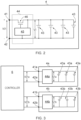
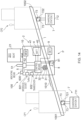
- a lift system 100 in the form of a stairlift, embodying the invention and comprising: at least one rail 1; a carriage assembly 2 comprising a seat or platform 21 for supporting a person to be conveyed along the rail, drive means 3 arranged to engage the rail and controllable to drive the carriage assembly along the rail, at least a first battery pack (module) 4 (as shown in fig. 2 ) arranged to power the drive means, input means 5 operable by a user to provide an input signal indicative of a desired movement of the carriage assembly along the rail, and control means (e.g.
- the seat or platform 21 comprises a seat having a back portion 211 and a base portion 212 for supporting a user seated on the seat 21.
- the drive means, or module, 3 comprises an electric motor, powered from the battery module 4 under the control of the control means 6, which has a rotor shaft 31 connected to a toothed gear 32 which is arranged to engage a toothed portion 1010 of the rail 1 (only a part of which is shown on the figure for clarity) such that rotation of the motor drives the carriage assembly 2 along the rail 1.
- Alternative embodiments may, of course, employ different forms of drive means, and the invention, in its broadest sense, is not limited to using any particular form of drive means.
- the input means 5 comprises a base 52 and joy stick 51 operable by the user, seated on the seat 21, to provide an input signal indicative of a desired direction of movement along the rail.
- different forms of input means may be employed, such as remote control units or handsets, keypads, input units with a plurality of control keys or buttons.
- the carriage assembly further comprises a connector or connection means 8 arranged to engage and provide electrical connection to the corresponding connectors or connection means 721, 722 of the charging means 7 when the carriage assembly is located either at the first, or lower, charge point CP1, or the second, or upper, charge point CP2.
- the connector 8 of the carriage assembly in this example comprises a pair of connection terminals 81 which engage with the corresponding connection terminals 73 of the lower charging means connector 721 or the upper charging connector 722 when the carriage assembly is at the first or second charging positions CP1, CP2 respectively.
- the carriage assembly in this embodiment further comprises a memory or memory means 10 adapted to store data used by the control means in the control of the movement of the carriage assembly along the rail.
- This data may include data indicative, for example, of the slope of the rail, the length of the rail, a map of the rail (particularly in embodiments where the slope and/or shape of the rail is not constant along its length), and data indicative of the programmed or appropriate speed of travel of the carriage assembly along the rail at different positions along its length.
- the carriage assembly also comprises a detector or detection means 9 operable to provide the control means with an indication of the instantaneous position of the carriage assembly along the rail, and/or the instantaneous slope and/or curvature of the rail, and/or the instantaneous speed of travel along the rail.
- Fig 1 the carriage assembly 2 is shown at an intermediate position, IP, between the upper and lower charging positions CP1 and CP2.
- the battery module 4 comprises a plurality of cells 43 connected in electrical parallel with one another, between the positive and negative output terminals 41, 42 of the battery module 4.
- the battery module further comprises a first protection circuit module 44 arranged to monitor a first voltage V1 across the parallel arrangement of the plurality of cells 43 and prevent further discharge of the plurality of cells 43 if that first voltage V1 falls below a first, predetermined threshold.
- the first protection circuit module 41 comprises a controllable switching device 46, in the form of an FET in this example, and a control circuit 45 arranged to monitor the voltage V1 across the cells 43 and open the controllable switching device 46 by means of supplying an appropriate control voltage to its gate terminal if that voltage V1 falls below the predetermined first threshold.
- the protection circuit module 44 disconnects the parallel arrangement of battery cells 43 from the output terminals 41, 42 when the voltage across those cells falls below the predetermined threshold.
- the cells are lithium-ion cells (Li-ion cells).
- alternative embodiments may employ different cells and batteries, including, but not limited to, NiCd, NiMH, Lithium Poly, and lead-acid.
- the control means 6 connected to the battery module 4 is thus able to monitor the voltage V1 across the cells, as, in this example, which comprises just one "pack" of parallel-connected cells, the output voltage VO1 across the output terminals 41, 42 is substantially equal to the cell voltage V1.
- a number of series-connected cell packs may be employed, in which case the output voltage is not equal to the cell voltage across just one of the packs.
- control means is further arranged so that if it detects the output voltage (equal to voltage V1 in this example) dropping below a second predetermined threshold (that second predetermined threshold being higher than the first predetermined threshold at which the protection circuit module 44 "disconnects" the cells and prevents further discharge) the control means in this example is arranged to prevent movement of the carriage assembly upwards along the rail towards the second charging position CP2, even if a user operates the input means 5 to indicate that further upward motion is desired.
- a second predetermined threshold that second predetermined threshold being higher than the first predetermined threshold at which the protection circuit module 44 "disconnects" the cells and prevents further discharge
- the control means is able to detect that the battery pack output voltage is getting dangerously low and prevent further upward movement before that automatic shut-down situation is reached.
- the controller is arranged so that it allows only downward movement of the carriage assembly along the rail, towards the lower charging point CP1, this downward movement of course consuming less power than upward movement.
- the controller when the controller detects that the battery module output voltage VO1 has fallen below the second, upper threshold when the carriage assembly is at an intermediate position, labelled IP in fig. 1 , it simply may allow the user only to move in the downward direction (in other words the user may simply receive no response to an input signal indicating a desire to move upwards, but in response to an input signal indicating a desire to move downwards the carriage assembly may move in that direction).
- the control means when the control means detects this condition, it may provide the user with a suitable indication, alerting the user to the fact that upward movement is not permitted, and indicating that the user should instead operate the input means to move the carriage assembly downwards to the lower charging position CP1.
- control means when the control means detects this condition it may automatically control the drive means to convey the carriage assembly down to the lower charging position CP1. When it reaches that position the controller may then cause the carriage assembly to remain at that position CP1 until the battery module 4 is sufficiently charged to enable travel up the rail to the upper charging point CP2. This may involve the control means monitoring the battery output voltage VO1 to detect when it exceeds the second predetermined threshold.
- the controller may be arranged to allow upward movement of the carriage assembly from the lower charge position CP1 upwards towards the upper charge position CP2 only when the battery output voltage VO1 has exceeded a third predetermined threshold, higher than the second threshold, where that third predetermined threshold has been selected as corresponding to a level of charge sufficient to provide the energy for conveying the carriage assembly all the way to the upper charge point CP2.
- Fig 3 this shows a controller (or control means) 6 and battery module arrangement.
- the controller is arranged to prevent further upward movement of the carriage assembly along the rail, and instead allow only movement in the downward direction, toward the lower charge point CP1. In this way, the carriage assembly is able to reach the lower charge point CP1 without either of the battery modules 4a, 4b being shut down by its respective protection circuit module 44a, 44b.
- embodiments of the invention employ a plurality of battery modules (e.g. 2, 3, or more).
- the battery pack is adapted to provide a warning signal itself.
- each battery pack produces a warning signal (at a cell pack voltage at least a little higher than the threshold voltage at which the PCM nay shut the pack down) which the controller then uses to control/inhibit movement (e.g. prevent upward movement).
- the controller may not need to monitor battery output voltage. Instead, it may inhibit movement in response to receiving the warning signal or alert from any one of the PCMs 44.
- each PCM may be arranged to shut down the respective battery pack at a first cell-pack threshold voltage, but before reaching that shut-down condition, emit a warning or alert signal to the controller in response to a cell-pack voltage alling below a second (higher) threshold voltage.
- the controller may, even without monitoring output voltage directly, receive an early indication of low-battery condition, and thus be able to inhibit motion and prevent battery pack shutdown, damage, and stranding of a user at an intermediate position.
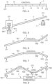
- FIG. 4 this is a highly schematic representation of a modular rail 1 which may be used in embodiments of the invention.
- the rail 1 comprises a plurality of rail sections 11 which are joined to provide the overall rail assembly along which a carriage may be conveyed.
- the rail 1 of Fig. 4 can be described as a horizontal rail with 0° inclination.
- each section 11 may be straight.
- one or more, or indeed all, of the sections 11 may be curved.
- the controller when the carriage assembly is at charge point CP1, or is at a position closer to charge point CP1 than CP2, may prevent movement of the carriage assembly towards charge point CP2 if the battery output voltage is below the appropriate threshold voltage.
- the charging method is inductive (i.e. contactless).
- Each charging station 711, 712 comprises a respective induction coil 701, 702 by means of which a time-varying magnetic field can be generated.
- a corresponding induction coil 601 coupled to the control means 6, senses the changing magnetic field generated by the charging station 1.
- a charging voltage and current can thus be induced in the carriage assembly, which the control means is able to direct so as to charge the battery pack or packs.
- the rail 1 is inclined at a fixed inclination according to the side view.
- the rail may or may not have curved sections, according to different embodiments.
- this shows a multi-sectional rail 1 which may be used in certain embodiments of the invention. It is a combination of a first inclined rail section 101, a horizontal section 102, followed by another inclined section 103 which may have a different inclination to the first inclined section 101. Again, in certain embodiments, such rail systems may or may not have curved sections.
- FIG. 7 shows another multi-sectional rail assembly which may be used in embodiments of the invention.
- the system comprises a first rail section 101 having positive slope, a second horizontal rail section 102, and a third inclined rail section 103 of negative slope.
- Charge point 1 is at the lower end of the first section
- charge point 2 is at the lower end of the third section 103.
- the controller may be arranged so that it inhibits movement away from either charge point CP1 or charge point CP2 if the battery output voltage is below the second predetermined threshold voltage (or other appropriate threshold voltage, in alternative embodiments of the invention) as any such movement would entail travelling first of all in an upwards direction.
- the carriage assembly may be adapted so that it knows its position along the rail, and/or can detect the slope of the portion of rail on which it is currently situated. Thus, when the carriage assembly is on the horizontal section of the rail it may know this, and if the battery output voltage (or one of the battery output voltages) falls below the relevant threshold, the controller may still permit movement of the carriage assembly, in response to user input, towards either the first charge point CP1 or the second charge point CP2, as either journey will involve just travel along a horizontal portion and then down along an inclined portion of the rail system.
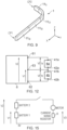
- FIG. 8 this shows part of another stair lift system embodying the invention comprising a multi-sectional rail assembly and a charging system comprising a charging power supply 730 and three charging stations 721, 722, 723, with corresponding charge points CP1, CP2, and CP3.
- the rail assembly comprises two horizontal portions 102 and 104, and three inclined sections 101, 103, and 105. Again, in certain embodiments, such rail systems may or may not have curved sections. If a low battery output voltage condition is detected while the carriage assembly is on horizontal section 102, the controller may be arranged still to allow movement towards either CP1 or CP2, as each journey involves no travel in an upwards direction.
- the controller may be arranged such that in response to detecting a low battery output voltage condition when the carriage assembly is on horizontal section 101, or more particularly at charge point 3, it prevents movement of the carriage assembly upwards along either section 103 or section 105.
- the controller may combine pre-knowledge of the rail profile with measurements of the battery pack output voltage to automatically inhibit motion of the carriage assembly along the rail under certain conditions.
- FIG. 9 shows another rail system 1 which may be used in embodiments of the invention.
- the rail 1 extends upwardly from a first charge point CP1, with two straight inclined sections 11SI.
- the rail then continues upwardly and curves to the left, in curved inclined section 11Cl, and then extends to the upper charge point CP2 along straight, non-inclined section 11S.
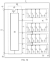
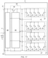
- One, or a plurality of power cells 47 are connected in series to define the voltage output of the battery pack.
- a plurality of cell packs 47 are connected in electrical series between the battery pack output terminals 41, 42, such that, when the transistor 46 is conducting, the voltage at the battery output terminals VO1 is equal to the sum of the cell pack voltages.
- the control circuit (45) is arranged to monitor the voltage of the cells 43 in each power pack 47, thus measuring cell pack voltages V1a, V1b, V1c across V1n. If the voltage of any cell 43 in any power cell (cell pack) 47 falls below the control circuit threshold (I.e. the first threshold) then the switching device 46 will be controlled to disable the battery pack output.
- the controller 6 of the carriage assembly monitors the external voltage, i.e. the output voltage VO1, and uses that voltage to determine whether or not to inhibit movement of the carriage assembly, before any of the cell packs triggers the battery pack to shut down.
- the choice of second threshold voltage has to be balanced between too high a value, where the low battery fault is triggered too early, reducing the number of journeys achievable with a fully charged pack, or too low where there is risk of PCM shutdown.
- the final value was determined by experiments on representative lifts and the number of successful journeys.
- the chosen second threshold voltage is 13.5V in certain embodiments.
- the battery pack voltages are sampled at a rate of 1300 samples per second, and eight samples are averaged so the effective new data rate is approximately 162 readings per second.
- the conversions are performed continuously; it does not matter what the lift is doing.
- the sample rate is high, and may be set at such a value to suit the analogue to digital subsystem which may need to monitor other signals this frequently.
- Fig. 12 this shows part of a lift system embodying the invention, comprising a controller 6 and two battery packs 4A, 4B connected in electrical series between controller input terminals 61 and 62.
- the two battery packs have the same specification.
- two battery packs are wired in series (as shown in fig. 12 ) to achieve the required 32V for the motors. Without controller intervention, one or other of the packs will shut down first. Measuring the 32V with one 'voltmeter' would be insufficient to determine whether a pack was about to shut down due to differences in the pack performance.
- An alternative differential analogue to digital converter could be used where the A/D has two wires per measurement channel and converts the voltage between the two wires rather that the voltage between a single wire and ground (0V). In this case the voltage across pack 4a could be measured directly.
- Methods embodying the invention may be applied to straight lift, curved lifts, and lifts incorporating both straight and curved sections Certain straight lifts use Lead Acid batteries, and like NiCd / NiMh batteries the battery output will just degrade rather than shut down as the batteries do not contain a PCM. Methods embodying the invention may thus be used to monitor the battery voltage in straight stairlifts to prevent the lift stopping halfway up the track.
- This monitoring of at least one voltage characteristic of the energy storage means and/or at least one operational characteristic of the stair lift, and generation of an alert signal in response to one or more of said characteristics, or a difference between one or more said characteristics, fulfilling a defined criterion, criteria, condition, or conditions, may also be employed in embodiments as described above with respect to figs 1 to 12 (i.e. it may be employed in addition to those features relating to prevention of movement away from a charge point to avoid the user being stranded).
- the carriage assembly further comprises indicating means 600 (e.g. an indicator) operable by the controller to provide the alert signal, or an indication that the alert signal has been generated, to a user of the system.
- the indicator may provide the alert signal or indication in any suitable form, for example a visual indication, an audible indication, a haptic indication, or any combination of such forms.
- the user may thus be alerted to a degradation in performance of one or both of the batteries or battery packs, so that she/he may contact a source of assistance before degradation reaches a level at which the user is stranded.
- the carriage assembly further comprises transmitting means in the form of a transceiver 602, by means of which the controller can transmit the alert signal, or an indication that the alert signal has been generated, to a remote location (for example a service or maintenance support centre). An engineer may then be sent out to replace at least one of the batteries/battery packs before failure occurs.
- the transceiver may also be used to receive signals from remote locations, for use by the control means and/or for providing to the user.
- control means has separate connections to the terminal 41a, terminal 42b, and the connected terminals 42a, 41b.
- the control means can monitor the voltages across each battery individually.
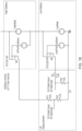
- Fig. 15 is a further illustration of battery measurement techniques in embodiments of the invention, such as that shown in fig. 13 , with energy storage means comprising a plurality of batteries/packs connected in series.
- Fig. 15 illustrates part of a lift powered by two batteries wired in series. The two batteries power the main motor (i.e. of the drive means).
- An additional low value resistor R is included to measure the motor current flow.
- the diagram illustrates the available measurements.
- the three voltages (V1, V2, V3) are sampled, for example at a rate greater than 1000 samples per second. In certain embodiments groups of samples (e.g. eight samples) are averaged to give an effective new data rate.
- the effective new data rate is greater than 100 readings per second.
- the conversions (A to D) are performed continuously in certain embodiments.
- the battery voltage readings may be calibrated during PCB testing resulting in an accuracy of 0.1V and a resolution of 0.02V, for example.
- the two batteries may be nominally identical, having the same specification, and the system may look for differences in battery characteristics/performance as an indication of degradation.
- the two batteries may be different, and instead of monitoring differences in characteristics/performance, one or more characteristic of each battery may be monitored against one or more respective criterion or condition.
- fig. 14 this illustrates another lift system embodying an aspect of the invention.
- the energy storage means comprises a single battery or battery pack 4, having output terminals 41, 42.
- the control means is arranged to monitor at least one voltage characteristic (including the voltage across the terminals 41, 42) of the energy storage means and/or at least one operational characteristic of the stair lift (or, more particularly, of its carriage assembly), and generate an alert signal in response to one or more of said characteristics, or a difference between one or more said characteristics, fulfilling a defined criterion, criteria, condition, or conditions.
- features of the embodiment of fig. 14 may be employed in embodiments also in accordance with those illustrated in figures 1 to 12 .
- Each of the battery monitoring techniques listed below, which may be employed in embodiments of the present invention is used to generate an alert signal (i.e. may result in a signal indication of a fault).
- the indication in certain embodiments may be presented visually, for example on a 7 segment display of the carriage assembly, or via a message sent to a remote location using wireless or other transmission methods. Additionally, logs within the lift may be maintained to allow a service engineer to access the fault history.
- the main motor of the drive means is driven from a Pulse Width Modulated signal (PWM).
- PWM Pulse Width Modulated signal
- the width of the PWM signal controls the average power applied to the motor and hence the motor output.
- the system is able to measure the lift speed.
- a feedback loop can be employed where the PWM drive (width) can be adjusted to maintain the required lift speed.
- the transit time for a bottom to top journey for certain such embodiments should always be the same as the speed is actively controlled.
- the motor effort required to maintain the constant speed will also vary. The variation in effort will be represented as an increase in the PWM width for a heavier passenger.
- a battery may be presented at the charging point with a voltage more than a certain amount (e.g. 2V) below the normal full charge value.
- the battery is charged to the full voltage, for example 13.8V for SLA and 15.2V for Lithium.
- the time taken to charge e.g. from 11.8 to 13.8V or 13.2 to 15.2V is measured.
- a failing battery will take less time than normal to reach 'full' charge. After a number of 'fast' charge cycles the battery can be flagged for replacement.
- the fully charged voltage of two series connected SLA batteries will tend to balance and settle at the same value providing the charger can provide a high enough charging voltage (e.g. at least 27.6V).
- a high enough charging voltage e.g. at least 27.6V.
- Two series connected Lithium battery packs will not naturally balance even with a 30.4V supply and additional active circuitry is required to balance the two Lithium batteries. In either case it should be possible to balance the no load voltage of two serially connected batteries.
- the full battery charge voltage is monitored over many months of service.
- the full battery voltage will reduce as the batteries age. Once the voltage has consistently fallen below a threshold value the batteries can be flagged for replacement.
- stair lifts may utilise Lithium batteries which can shut down during a passenger movement leaving the client stranded in the middle of the track.
- PCM protection circuit module
- a PCM shut down is necessary to prevent damage to the Lithium batteries.
- the PCM shut down must be avoided to prevent marooned passengers. In certain embodiments this is achieved by monitoring the individual battery pack voltages during the lift movement. If the voltage approaches the PCM shut down threshold then the lift is stopped and further upward movement of the lift is prevented. Movement in the downward direction is permitted as the demands on the battery are much lower.
- the battery voltage may be measured when the passenger initiates a movement request. Hence an upward journey is prevented if it is unlikely to be completed.
- the external monitoring of the Lithium battery pack is not always ideal as the only measurement accessible to the lift circuitry may be the nominal 14.8V of the complete battery pack.
- the Lithium battery is constructed from multiple cells. Internally the PCM monitors the individual cell voltage and shuts down the battery output to prevent excessive discharge or overcurrent when only one of the individual cells falls below the voltage threshold. As the lift circuitry of certain embodiments does not have access to the individual cells the lift could potentially sometimes miss the imminent PCM shut down. Conversely if the lift voltage thresholds are set too high above the PCM thresholds then premature PCM shut down warnings are given preventing the use of the full battery capacity.
- the PCM monitors the individual cells to determine when to shut down the output. For example the PCM could be designed to shut down the output if a cell voltage falls below 2.8V. A duplicate of the cell monitoring circuit is added within the battery but configured with a slightly higher threshold voltage of say 3.0V. The additional circuit is arranged to signal an early warning of the imminent PCM shut down allowing the lift to take appropriate action to prevent the real PCM shut down.
- Each battery will now have three connections, the main power and return high current wires, plus an additional low power 'battery good' signal.
- the battery pack (4) is constructed from numerous individual cells connected in a series / parallel format.
- the lift controller monitors the external voltage V1 and the good battery signal Vg.
- Vg is now asserted high (good) at the reduced travel speed
- the journey may be completed (i.e. the controller may not intervene to inhibit further upward movement).
- reducing the speed may allow the batteries to complete the journey and then recharge (e.g. at the higher charging station) without the PCM shut down.
- the battery pack 4 also comprises a second circuit module 48 arranged to monitor said first voltage and generate an output signal Vg indicative of whether said first voltage is above or below a second threshold, the second threshold being higher than the first threshold.
- the control means 6 is arranged to receive that output signal (or warning, or battery condition signal) Vg, and, if the output signal indicates that the first voltage is below the second threshold, prevent movement of the carriage assembly along the rail in a direction away from the first charging position, for example towards the second charging position, but allow movement of the carriage assembly along the rail in a direction towards the first charging position when the carriage assembly is located away from the first charging position, for example between the first and second charging positions.
- the controller may intervene before the voltage across one cell or group of cells of the battery pack has dropped lower enough to trigger shut down by the first circuit module.
- the controller may be further arranged, in response to the output signal indicating that said first voltage is below the second threshold while the carriage assembly is travelling along the rail at a first speed, to control the drive means to reduce the speed of travel to a second speed. Then, the controller may be further arranged to monitor the output signal after reducing the speed of travel, and, if the output signal indicates that the first voltage has risen above the second threshold as a result of that speed reduction, allow movement of the carriage assembly away from the first charging position. Alternatively, if the output signal indicates that the first voltage is still below the second threshold after reducing speed, the controller may prevent movement of the carriage assembly away from the first charging position, allowing movement only towards the first charging position.
Landscapes
- Engineering & Computer Science (AREA)
- Automation & Control Theory (AREA)
- Transportation (AREA)
- Structural Engineering (AREA)
- Mechanical Engineering (AREA)
- Charge And Discharge Circuits For Batteries Or The Like (AREA)
- Secondary Cells (AREA)
- Types And Forms Of Lifts (AREA)
- Electric Propulsion And Braking For Vehicles (AREA)
Claims (10)
- Liftsystem, umfassendeine Schiene (1);eine Wagenanordnung (2), umfassend einen Sitz oder eine Plattform zum Tragen einer Person, die entlang der Schiene befördert werden soll, Antriebseinrichtungen (3), die angeordnet sind, die Schiene einzugreifen und gesteuert werden kann, um die Wagenanordnung entlang der Schiene anzutreiben, Energiespeichereinrichtungen (4), die angeordnet sind, um die Antriebseinrichtungen mit Energie zu versorgen, Eingabeeinrichtungen, die von einem Benutzer betätigt werden können, um ein Eingangssignal bereitzustellen, das indikativ für eine gewünschte Bewegung der Wagenanordnung entlang der Schiene ist, und Steuereinrichtungen (6), die angeordnet sind, um das Eingangssignal zu empfangen und die Antriebseinrichtungen als Reaktion auf das Eingangssignal zu steuern; und Ladeeinrichtungen (7), die angeordnet sind, um die Energiespeichereinrichtungen aufzuladen, wenn die Wagenanordnung an einer ersten Ladeposition auf der Schiene ist,wobei die Steuereinrichtungen angeordnet sind, um mindestens eine Spannungscharakteristik der Energiespeichereinrichtungen zu überwachen und ein Warnsignal zu erzeugen, wenn eine oder mehrere dieser Charakteristiken oder eine Differenz zwischen einer oder mehreren dieser Charakteristiken ein definiertes Kriterium, von definierten Kriterien, einer definierten Bedingung oder von definierten Bedingungen erfüllt, unddie Energiespeichereinrichtungen umfassend eine erste Batterie oder ein erstes Batteriepaket (4a), die/das einen jeweiligen ersten und zweiten Batterieanschluss aufweist, und eine zweite Batterie oder ein zweites Batteriepaket (4b), die/das einen jeweiligen ersten und zweiten Batterieanschluss aufweist, wobei die erste und die zweite Batterie oder Batteriepaket in Reihe miteinander verbunden sind, um einen Antriebsstrom an die Antriebseinrichtungen zuzuführen, wobei die mindestens eine Spannungscharakteristik eine erste Spannung zwischen dem ersten und dem zweiten Batterieanschluss der ersten Batterie oder Batteriepakets und eine zweite Spannung zwischen dem ersten und dem zweiten Batterieanschluss der zweiten Batterie oder Batteriepakets umfasst,wobei ein Erfüllen eines definierten Kriteriums, von definierten Kriterien, einer definierten Bedingung oder von definierten Bedingungen Folgendes umfasst:eine von der ersten und der zweiten Spannung fällt unter einen Schwellenwert; odereine Differenz zwischen der ersten und der zweiten Spannung überschreitet einen Schwellenwert.
- System nach Anspruch 1, wobei die Wagenanordnung ferner einen Speicher umfasst und wobei die Steuereinrichtung angeordnet ist, um das Alarmsignal oder Daten, die indikativ dafür sind, dass das Alarmsignal erzeugt wurde, in dem Speicher zu speichern.
- System nach Anspruch 1 oder Anspruch 2, wobei die Wagenanordnung ferner Angabeeinrichtungen umfasst, die angeordnet sind, um einem Benutzer des Liftsystems das Alarmsignal oder eine Angabe, dass das Alarmsignal erzeugt wurde, bereitzustellen.
- System nach einem der vorhergehenden Ansprüche, wobei die Wagenanordnung ferner eine Sendeeinrichtungen umfasst, die angeordnet sind, um das Alarmsignal oder einen Hinweis darauf, dass das Alarmsignal erzeugt worden ist, zum Empfang an einem vom Liftsystem entfernten Ort zu senden.
- System nach einem der vorhergehenden Ansprüche, wobei die Wagenanordnung ferner eine Schnittstelle umfasst, um das Alarmsignal oder eine Angabe, dass das Alarmsignal erzeugt worden ist, an ein externes Gerät bereitzustellen, wenn es mit der Schnittstelle verbunden ist.
- System nach einem der Ansprüche 1 bis 5, wobei die Differenz zwischen der ersten und der zweiten Spannung eine Differenz bei Nulllast ist.
- System nach einem der Ansprüche 1 bis 5, wobei die Differenz zwischen der ersten und der zweiten Spannung eine Differenz unter Last ist.
- System nach einem der Ansprüche 1 bis 6, wobei die Differenz zwischen der ersten und der zweiten Spannung eine Differenz zwischen den jeweiligen Spannungen ist, auf die die Batterien nach einer Belastung zurückgekehrt sind.
- System nach einem der Ansprüche 1 bis 6, wobei die Differenz zwischen der ersten und der zweiten Spannung eine Differenz nach Laden der ersten und der zweiten Batterie in Reihe und vor einem Laden ist.
- System nach einem der vorherigen Ansprüche, wobei die mindestens eine Spannungscharakteristik der Energiespeichereinrichtungen und/oder mindestens eine Betriebscharakteristik des Liftsystems eine jeweilige Erholungszeit für die Spannung an jedem Paar von Batterieanschlüssen umfasst, um von einem Wert unter Last auf einen stabilen Wert unter Nulllast zurückzukehren.
Applications Claiming Priority (3)
| Application Number | Priority Date | Filing Date | Title |
|---|---|---|---|
| GB1517307.3A GB2542822B (en) | 2015-09-30 | 2015-09-30 | Lift system and method |
| GB1611312.8A GB2542883B (en) | 2015-09-30 | 2016-06-29 | Lift system and method |
| PCT/GB2016/053031 WO2017055849A2 (en) | 2015-09-30 | 2016-09-29 | Lift system and method |
Publications (2)
| Publication Number | Publication Date |
|---|---|
| EP3356274A2 EP3356274A2 (de) | 2018-08-08 |
| EP3356274B1 true EP3356274B1 (de) | 2023-05-31 |
Family
ID=54544360
Family Applications (1)
| Application Number | Title | Priority Date | Filing Date |
|---|---|---|---|
| EP16777762.2A Active EP3356274B1 (de) | 2015-09-30 | 2016-09-29 | Leistungsverwaltung einer batterie eines treppenliftsystems |
Country Status (7)
| Country | Link |
|---|---|
| US (2) | US11254541B2 (de) |
| EP (1) | EP3356274B1 (de) |
| AU (2) | AU2016332625B2 (de) |
| CA (2) | CA3000624C (de) |
| GB (3) | GB2542822B (de) |
| WO (1) | WO2017055849A2 (de) |
| ZA (1) | ZA201802477B (de) |
Families Citing this family (12)
| Publication number | Priority date | Publication date | Assignee | Title |
|---|---|---|---|---|
| GB2542822B (en) | 2015-09-30 | 2021-03-24 | Acorn Mobility Services Ltd | Lift system and method |
| EP3290375B1 (de) * | 2016-08-29 | 2019-06-26 | KONE Corporation | Aufzug |
| GB2558672B (en) * | 2017-01-17 | 2022-02-02 | Stannah Stairlifts Ltd | Improvements in or relating to stairlifts |
| EP3521232A1 (de) * | 2018-02-02 | 2019-08-07 | KONE Corporation | Elektrischer linearmotor |
| CN108258775B (zh) * | 2018-03-16 | 2024-06-21 | 江苏跨境数据科技有限公司 | 一种基于nb-iot通讯协议的多个充电宝借还设备 |
| CN108599108B (zh) | 2018-04-30 | 2023-11-17 | 上海晶丰明源半导体股份有限公司 | 保护电路、驱动系统、芯片及电路保护方法、驱动方法 |
| GB2576150A (en) * | 2018-08-06 | 2020-02-12 | Stannah Stairlifts Ltd | Improvements in or relating to stairlifts |
| EP3738916A1 (de) * | 2019-05-15 | 2020-11-18 | KONE Corporation | Schrägaufzug und verfahren zur herstellung davon |
| USD933330S1 (en) | 2019-05-31 | 2021-10-12 | Bruno Independent Living Aids, Inc. | Stairlift rail |
| US11834302B2 (en) * | 2019-05-31 | 2023-12-05 | Bruno Independent Living Aids, Inc. | Stairlift |
| CA3142279A1 (en) | 2019-05-31 | 2020-12-03 | Bruno Independent Living Aids, Inc. | Stairlift rail and method of forming same |
| US12208993B2 (en) * | 2019-05-31 | 2025-01-28 | Bruno Independent Living Aids, Inc. | Multi-function stairlift connectivity system |
Citations (8)
| Publication number | Priority date | Publication date | Assignee | Title |
|---|---|---|---|---|
| US3786343A (en) | 1973-03-19 | 1974-01-15 | Us Navy | Battery monitor system |
| US4315217A (en) | 1979-09-10 | 1982-02-09 | Sharber John M | Battery analyzer for electric golf carts |
| US4352067A (en) | 1980-06-02 | 1982-09-28 | Dc Electronic Industries, Inc. | Battery analyzer |
| JPH08677A (ja) * | 1994-06-16 | 1996-01-09 | O G Giken Kk | 天井走行リフト |
| EP1235323A1 (de) | 1999-11-17 | 2002-08-28 | Fujitec Co., Ltd | Stromversorgung für wechselstromaufsug |
| GB2397289A (en) * | 2000-08-10 | 2004-07-21 | Minivator Ltd | A stairlift assembly with angled rack and pinion |
| JP2009083978A (ja) | 2007-09-28 | 2009-04-23 | Toshiba Corp | 階段昇降機 |
| GB2510810A (en) * | 2012-12-14 | 2014-08-20 | Stannah Stairlifts Ltd | Improvements in or relating to stairlifts |
Family Cites Families (11)
| Publication number | Priority date | Publication date | Assignee | Title |
|---|---|---|---|---|
| GB2137589B (en) * | 1983-02-17 | 1987-01-14 | Antony Stopher | Stairlift |
| US4904916A (en) * | 1988-05-18 | 1990-02-27 | The Cheney Company | Electrical control system for stairway wheelchair lift |
| JPH05162942A (ja) | 1991-12-17 | 1993-06-29 | Mitsubishi Electric Corp | エレベータの遠隔監視装置 |
| US20080128213A1 (en) * | 2006-11-30 | 2008-06-05 | Harris Timothy R | Combination electrical and battery-powered control system for stairway chairlift |
| CA2767232A1 (en) * | 2009-07-08 | 2011-01-13 | Cwa Constructions Sa | Aerial cable car system having transportation operating equipment for passenger and/or freight transport |
| US20120104818A1 (en) * | 2010-04-30 | 2012-05-03 | Dennis Kimble Morris | Portable, Powered Chair Lift |
| JP5749040B2 (ja) * | 2011-03-04 | 2015-07-15 | ティッセンクルップ・アクセス・ジャパン株式会社 | 階段昇降機および階段昇降機用監視装置 |
| CN102556778B (zh) * | 2011-12-31 | 2014-01-08 | 太仓市康辉科技发展有限公司 | 楼梯升降椅控制装置 |
| GB2536909A (en) * | 2015-03-30 | 2016-10-05 | Stannah Stairlifts Ltd | Improvements in or relating to stairlifts |
| GB2542822B (en) | 2015-09-30 | 2021-03-24 | Acorn Mobility Services Ltd | Lift system and method |
| US10769926B1 (en) * | 2018-03-13 | 2020-09-08 | Alarm.Com Incorporated | Stair lift monitoring |
-
2015
- 2015-09-30 GB GB1517307.3A patent/GB2542822B/en active Active
-
2016
- 2016-06-29 GB GB2102000.3A patent/GB2590028B/en active Active
- 2016-06-29 GB GB1611312.8A patent/GB2542883B/en active Active
- 2016-09-29 WO PCT/GB2016/053031 patent/WO2017055849A2/en not_active Ceased
- 2016-09-29 CA CA3000624A patent/CA3000624C/en active Active
- 2016-09-29 AU AU2016332625A patent/AU2016332625B2/en active Active
- 2016-09-29 EP EP16777762.2A patent/EP3356274B1/de active Active
- 2016-09-29 CA CA3076067A patent/CA3076067C/en active Active
- 2016-09-29 US US15/763,688 patent/US11254541B2/en active Active
-
2018
- 2018-04-16 ZA ZA2018/02477A patent/ZA201802477B/en unknown
-
2020
- 2020-08-24 AU AU2020223642A patent/AU2020223642B2/en active Active
-
2022
- 2022-01-12 US US17/573,795 patent/US11780708B2/en active Active
Patent Citations (8)
| Publication number | Priority date | Publication date | Assignee | Title |
|---|---|---|---|---|
| US3786343A (en) | 1973-03-19 | 1974-01-15 | Us Navy | Battery monitor system |
| US4315217A (en) | 1979-09-10 | 1982-02-09 | Sharber John M | Battery analyzer for electric golf carts |
| US4352067A (en) | 1980-06-02 | 1982-09-28 | Dc Electronic Industries, Inc. | Battery analyzer |
| JPH08677A (ja) * | 1994-06-16 | 1996-01-09 | O G Giken Kk | 天井走行リフト |
| EP1235323A1 (de) | 1999-11-17 | 2002-08-28 | Fujitec Co., Ltd | Stromversorgung für wechselstromaufsug |
| GB2397289A (en) * | 2000-08-10 | 2004-07-21 | Minivator Ltd | A stairlift assembly with angled rack and pinion |
| JP2009083978A (ja) | 2007-09-28 | 2009-04-23 | Toshiba Corp | 階段昇降機 |
| GB2510810A (en) * | 2012-12-14 | 2014-08-20 | Stannah Stairlifts Ltd | Improvements in or relating to stairlifts |
Also Published As
| Publication number | Publication date |
|---|---|
| EP3356274A2 (de) | 2018-08-08 |
| US11254541B2 (en) | 2022-02-22 |
| US11780708B2 (en) | 2023-10-10 |
| AU2016332625A1 (en) | 2018-05-10 |
| WO2017055849A3 (en) | 2017-05-11 |
| GB201517307D0 (en) | 2015-11-11 |
| GB2542822A (en) | 2017-04-05 |
| CA3000624C (en) | 2020-04-28 |
| US20220135376A1 (en) | 2022-05-05 |
| ZA201802477B (en) | 2020-06-24 |
| WO2017055849A2 (en) | 2017-04-06 |
| GB201611312D0 (en) | 2016-08-10 |
| AU2016332625B2 (en) | 2020-05-28 |
| CA3000624A1 (en) | 2017-04-06 |
| AU2020223642B2 (en) | 2022-08-25 |
| CA3076067A1 (en) | 2017-04-06 |
| GB2590028B (en) | 2021-09-01 |
| US20190047825A1 (en) | 2019-02-14 |
| GB2590028A (en) | 2021-06-16 |
| GB2542822B (en) | 2021-03-24 |
| GB2542883B (en) | 2021-03-24 |
| AU2020223642A1 (en) | 2020-09-10 |
| CA3076067C (en) | 2023-03-14 |
| GB2542883A (en) | 2017-04-05 |
| GB202102000D0 (en) | 2021-03-31 |
Similar Documents
| Publication | Publication Date | Title |
|---|---|---|
| US11780708B2 (en) | Power management of a battery of a stair lift system | |
| US10587127B2 (en) | Charging device, charging control method, electricity storage device, power storage device, power system, and electric vehicle | |
| CN101595620B (zh) | 电源系统及电源系统的电力供应控制方法 | |
| US9176195B2 (en) | Method of detecting battery degradation level | |
| EP2161812A1 (de) | Stromversorgungssystem und stromversorgungssteuerverfahren und stromversorgungssteuerprogramm in dem stromversorgungssystem | |
| EP3410558A1 (de) | Batteriesteuerungsvorrichtung | |
| US20020153865A1 (en) | Uninterruptible power supply system having an NiMH or Li-ion battery | |
| US8736232B2 (en) | Full charge capacity correction circuit, charging system, battery pack and full charge capacity correction method | |
| EP2367261A2 (de) | Gleichstromquellenvorrichtung | |
| CN114867627B (zh) | 用于运行电动车辆的方法和电动车辆 | |
| US9658293B2 (en) | Power supply unit, vehicle and storage battery unit equipped with power supply unit, and remaining capacity detecting method of battery | |
| CN106469930A (zh) | 电池系统 | |
| CN101563828A (zh) | 电源系统、电源系统的供电控制方法、程序以及记录该程序的可由计算机读取的记录介质 | |
| JP2015223008A (ja) | 電源装置及びこの電源装置を備える電動車両並びに蓄電装置 | |
| KR101702379B1 (ko) | 모듈형 능동 셀밸런싱 장치, 모듈형 배터리 블록, 배터리 팩, 및 에너지 저장 시스템 | |
| JP2011221012A (ja) | バッテリモジュール状態検出装置、バッテリモジュール状態制御装置、バッテリシステム、電動車両、移動体、電力貯蔵装置および電源装置 | |
| US20230021796A1 (en) | Method for operating an electric vehicle and electric vehicle | |
| KR101373850B1 (ko) | 유선 비행체의 전원공급시스템 | |
| KR20180126168A (ko) | 에너지 저장 시스템의 안정화 및 효율적 관리를 위하여 배터리의 상태를 주기적으로 모니터링 및 제어하는 시스템 | |
| US20150229141A1 (en) | Flowing electrolyte battery maintenance bus system and method | |
| OA21490A (en) | Rechargeable battery discharge device for discharging rechargeable batteries, and method for discharging a plurality of rechargeable batteries. | |
| HK1198361A1 (zh) | 电梯控制装置 | |
| HK1198361B (en) | Elevator control device |
Legal Events
| Date | Code | Title | Description |
|---|---|---|---|
| STAA | Information on the status of an ep patent application or granted ep patent |
Free format text: STATUS: UNKNOWN |
|
| STAA | Information on the status of an ep patent application or granted ep patent |
Free format text: STATUS: THE INTERNATIONAL PUBLICATION HAS BEEN MADE |
|
| PUAI | Public reference made under article 153(3) epc to a published international application that has entered the european phase |
Free format text: ORIGINAL CODE: 0009012 |
|
| STAA | Information on the status of an ep patent application or granted ep patent |
Free format text: STATUS: REQUEST FOR EXAMINATION WAS MADE |
|
| 17P | Request for examination filed |
Effective date: 20180426 |
|
| AK | Designated contracting states |
Kind code of ref document: A2 Designated state(s): AL AT BE BG CH CY CZ DE DK EE ES FI FR GB GR HR HU IE IS IT LI LT LU LV MC MK MT NL NO PL PT RO RS SE SI SK SM TR |
|
| AX | Request for extension of the european patent |
Extension state: BA ME |
|
| DAV | Request for validation of the european patent (deleted) | ||
| DAX | Request for extension of the european patent (deleted) | ||
| STAA | Information on the status of an ep patent application or granted ep patent |
Free format text: STATUS: EXAMINATION IS IN PROGRESS |
|
| PUAG | Search results despatched under rule 164(2) epc together with communication from examining division |
Free format text: ORIGINAL CODE: 0009017 |
|
| 17Q | First examination report despatched |
Effective date: 20200921 |
|
| 17Q | First examination report despatched |
Effective date: 20200925 |
|
| B565 | Issuance of search results under rule 164(2) epc |
Effective date: 20200925 |
|
| RIC1 | Information provided on ipc code assigned before grant |
Ipc: B66B 9/08 20060101AFI20200922BHEP |
|
| GRAP | Despatch of communication of intention to grant a patent |
Free format text: ORIGINAL CODE: EPIDOSNIGR1 |
|
| STAA | Information on the status of an ep patent application or granted ep patent |
Free format text: STATUS: GRANT OF PATENT IS INTENDED |
|
| INTG | Intention to grant announced |
Effective date: 20221209 |
|
| GRAS | Grant fee paid |
Free format text: ORIGINAL CODE: EPIDOSNIGR3 |
|
| GRAA | (expected) grant |
Free format text: ORIGINAL CODE: 0009210 |
|
| STAA | Information on the status of an ep patent application or granted ep patent |
Free format text: STATUS: THE PATENT HAS BEEN GRANTED |
|
| AK | Designated contracting states |
Kind code of ref document: B1 Designated state(s): AL AT BE BG CH CY CZ DE DK EE ES FI FR GB GR HR HU IE IS IT LI LT LU LV MC MK MT NL NO PL PT RO RS SE SI SK SM TR |
|
| REG | Reference to a national code |
Ref country code: GB Ref legal event code: FG4D Ref country code: CH Ref legal event code: EP |
|
| REG | Reference to a national code |
Ref country code: DE Ref legal event code: R096 Ref document number: 602016079714 Country of ref document: DE |
|
| P01 | Opt-out of the competence of the unified patent court (upc) registered |
Effective date: 20230425 |
|
| REG | Reference to a national code |
Ref country code: AT Ref legal event code: REF Ref document number: 1570831 Country of ref document: AT Kind code of ref document: T Effective date: 20230615 |
|
| REG | Reference to a national code |
Ref country code: IE Ref legal event code: FG4D |
|
| REG | Reference to a national code |
Ref country code: LT Ref legal event code: MG9D |
|
| REG | Reference to a national code |
Ref country code: NL Ref legal event code: MP Effective date: 20230531 |
|
| REG | Reference to a national code |
Ref country code: AT Ref legal event code: MK05 Ref document number: 1570831 Country of ref document: AT Kind code of ref document: T Effective date: 20230531 |
|
| PG25 | Lapsed in a contracting state [announced via postgrant information from national office to epo] |
Ref country code: SE Free format text: LAPSE BECAUSE OF FAILURE TO SUBMIT A TRANSLATION OF THE DESCRIPTION OR TO PAY THE FEE WITHIN THE PRESCRIBED TIME-LIMIT Effective date: 20230531 Ref country code: NO Free format text: LAPSE BECAUSE OF FAILURE TO SUBMIT A TRANSLATION OF THE DESCRIPTION OR TO PAY THE FEE WITHIN THE PRESCRIBED TIME-LIMIT Effective date: 20230831 Ref country code: ES Free format text: LAPSE BECAUSE OF FAILURE TO SUBMIT A TRANSLATION OF THE DESCRIPTION OR TO PAY THE FEE WITHIN THE PRESCRIBED TIME-LIMIT Effective date: 20230531 Ref country code: AT Free format text: LAPSE BECAUSE OF FAILURE TO SUBMIT A TRANSLATION OF THE DESCRIPTION OR TO PAY THE FEE WITHIN THE PRESCRIBED TIME-LIMIT Effective date: 20230531 |
|
| PG25 | Lapsed in a contracting state [announced via postgrant information from national office to epo] |
Ref country code: RS Free format text: LAPSE BECAUSE OF FAILURE TO SUBMIT A TRANSLATION OF THE DESCRIPTION OR TO PAY THE FEE WITHIN THE PRESCRIBED TIME-LIMIT Effective date: 20230531 Ref country code: PL Free format text: LAPSE BECAUSE OF FAILURE TO SUBMIT A TRANSLATION OF THE DESCRIPTION OR TO PAY THE FEE WITHIN THE PRESCRIBED TIME-LIMIT Effective date: 20230531 Ref country code: NL Free format text: LAPSE BECAUSE OF FAILURE TO SUBMIT A TRANSLATION OF THE DESCRIPTION OR TO PAY THE FEE WITHIN THE PRESCRIBED TIME-LIMIT Effective date: 20230531 Ref country code: LV Free format text: LAPSE BECAUSE OF FAILURE TO SUBMIT A TRANSLATION OF THE DESCRIPTION OR TO PAY THE FEE WITHIN THE PRESCRIBED TIME-LIMIT Effective date: 20230531 Ref country code: LT Free format text: LAPSE BECAUSE OF FAILURE TO SUBMIT A TRANSLATION OF THE DESCRIPTION OR TO PAY THE FEE WITHIN THE PRESCRIBED TIME-LIMIT Effective date: 20230531 Ref country code: IS Free format text: LAPSE BECAUSE OF FAILURE TO SUBMIT A TRANSLATION OF THE DESCRIPTION OR TO PAY THE FEE WITHIN THE PRESCRIBED TIME-LIMIT Effective date: 20230930 Ref country code: HR Free format text: LAPSE BECAUSE OF FAILURE TO SUBMIT A TRANSLATION OF THE DESCRIPTION OR TO PAY THE FEE WITHIN THE PRESCRIBED TIME-LIMIT Effective date: 20230531 Ref country code: GR Free format text: LAPSE BECAUSE OF FAILURE TO SUBMIT A TRANSLATION OF THE DESCRIPTION OR TO PAY THE FEE WITHIN THE PRESCRIBED TIME-LIMIT Effective date: 20230901 |
|
| PG25 | Lapsed in a contracting state [announced via postgrant information from national office to epo] |
Ref country code: FI Free format text: LAPSE BECAUSE OF FAILURE TO SUBMIT A TRANSLATION OF THE DESCRIPTION OR TO PAY THE FEE WITHIN THE PRESCRIBED TIME-LIMIT Effective date: 20230531 |
|
| PG25 | Lapsed in a contracting state [announced via postgrant information from national office to epo] |
Ref country code: SK Free format text: LAPSE BECAUSE OF FAILURE TO SUBMIT A TRANSLATION OF THE DESCRIPTION OR TO PAY THE FEE WITHIN THE PRESCRIBED TIME-LIMIT Effective date: 20230531 |
|
| PG25 | Lapsed in a contracting state [announced via postgrant information from national office to epo] |
Ref country code: SM Free format text: LAPSE BECAUSE OF FAILURE TO SUBMIT A TRANSLATION OF THE DESCRIPTION OR TO PAY THE FEE WITHIN THE PRESCRIBED TIME-LIMIT Effective date: 20230531 Ref country code: SK Free format text: LAPSE BECAUSE OF FAILURE TO SUBMIT A TRANSLATION OF THE DESCRIPTION OR TO PAY THE FEE WITHIN THE PRESCRIBED TIME-LIMIT Effective date: 20230531 Ref country code: RO Free format text: LAPSE BECAUSE OF FAILURE TO SUBMIT A TRANSLATION OF THE DESCRIPTION OR TO PAY THE FEE WITHIN THE PRESCRIBED TIME-LIMIT Effective date: 20230531 Ref country code: PT Free format text: LAPSE BECAUSE OF FAILURE TO SUBMIT A TRANSLATION OF THE DESCRIPTION OR TO PAY THE FEE WITHIN THE PRESCRIBED TIME-LIMIT Effective date: 20231002 Ref country code: EE Free format text: LAPSE BECAUSE OF FAILURE TO SUBMIT A TRANSLATION OF THE DESCRIPTION OR TO PAY THE FEE WITHIN THE PRESCRIBED TIME-LIMIT Effective date: 20230531 Ref country code: DK Free format text: LAPSE BECAUSE OF FAILURE TO SUBMIT A TRANSLATION OF THE DESCRIPTION OR TO PAY THE FEE WITHIN THE PRESCRIBED TIME-LIMIT Effective date: 20230531 Ref country code: CZ Free format text: LAPSE BECAUSE OF FAILURE TO SUBMIT A TRANSLATION OF THE DESCRIPTION OR TO PAY THE FEE WITHIN THE PRESCRIBED TIME-LIMIT Effective date: 20230531 |
|
| REG | Reference to a national code |
Ref country code: DE Ref legal event code: R026 Ref document number: 602016079714 Country of ref document: DE |
|
| PLBI | Opposition filed |
Free format text: ORIGINAL CODE: 0009260 |
|
| PLAX | Notice of opposition and request to file observation + time limit sent |
Free format text: ORIGINAL CODE: EPIDOSNOBS2 |
|
| 26 | Opposition filed |
Opponent name: STANNAH STAIRLIFTS LIMITED Effective date: 20240228 |
|
| REG | Reference to a national code |
Ref country code: CH Ref legal event code: PL |
|
| PG25 | Lapsed in a contracting state [announced via postgrant information from national office to epo] |
Ref country code: SI Free format text: LAPSE BECAUSE OF FAILURE TO SUBMIT A TRANSLATION OF THE DESCRIPTION OR TO PAY THE FEE WITHIN THE PRESCRIBED TIME-LIMIT Effective date: 20230531 |
|
| PG25 | Lapsed in a contracting state [announced via postgrant information from national office to epo] |
Ref country code: LU Free format text: LAPSE BECAUSE OF NON-PAYMENT OF DUE FEES Effective date: 20230929 |
|
| REG | Reference to a national code |
Ref country code: BE Ref legal event code: MM Effective date: 20230930 |
|
| PG25 | Lapsed in a contracting state [announced via postgrant information from national office to epo] |
Ref country code: SI Free format text: LAPSE BECAUSE OF FAILURE TO SUBMIT A TRANSLATION OF THE DESCRIPTION OR TO PAY THE FEE WITHIN THE PRESCRIBED TIME-LIMIT Effective date: 20230531 Ref country code: LU Free format text: LAPSE BECAUSE OF NON-PAYMENT OF DUE FEES Effective date: 20230929 Ref country code: IT Free format text: LAPSE BECAUSE OF FAILURE TO SUBMIT A TRANSLATION OF THE DESCRIPTION OR TO PAY THE FEE WITHIN THE PRESCRIBED TIME-LIMIT Effective date: 20230531 Ref country code: MC Free format text: LAPSE BECAUSE OF FAILURE TO SUBMIT A TRANSLATION OF THE DESCRIPTION OR TO PAY THE FEE WITHIN THE PRESCRIBED TIME-LIMIT Effective date: 20230531 |
|
| REG | Reference to a national code |
Ref country code: IE Ref legal event code: MM4A |
|
| PG25 | Lapsed in a contracting state [announced via postgrant information from national office to epo] |
Ref country code: IE Free format text: LAPSE BECAUSE OF NON-PAYMENT OF DUE FEES Effective date: 20230929 |
|
| PLBB | Reply of patent proprietor to notice(s) of opposition received |
Free format text: ORIGINAL CODE: EPIDOSNOBS3 |
|
| PG25 | Lapsed in a contracting state [announced via postgrant information from national office to epo] |
Ref country code: CH Free format text: LAPSE BECAUSE OF NON-PAYMENT OF DUE FEES Effective date: 20230930 |
|
| PG25 | Lapsed in a contracting state [announced via postgrant information from national office to epo] |
Ref country code: IE Free format text: LAPSE BECAUSE OF NON-PAYMENT OF DUE FEES Effective date: 20230929 Ref country code: CH Free format text: LAPSE BECAUSE OF NON-PAYMENT OF DUE FEES Effective date: 20230930 |
|
| PG25 | Lapsed in a contracting state [announced via postgrant information from national office to epo] |
Ref country code: BE Free format text: LAPSE BECAUSE OF NON-PAYMENT OF DUE FEES Effective date: 20230930 |
|
| PG25 | Lapsed in a contracting state [announced via postgrant information from national office to epo] |
Ref country code: BG Free format text: LAPSE BECAUSE OF FAILURE TO SUBMIT A TRANSLATION OF THE DESCRIPTION OR TO PAY THE FEE WITHIN THE PRESCRIBED TIME-LIMIT Effective date: 20230531 |
|
| PG25 | Lapsed in a contracting state [announced via postgrant information from national office to epo] |
Ref country code: BG Free format text: LAPSE BECAUSE OF FAILURE TO SUBMIT A TRANSLATION OF THE DESCRIPTION OR TO PAY THE FEE WITHIN THE PRESCRIBED TIME-LIMIT Effective date: 20230531 |
|
| PG25 | Lapsed in a contracting state [announced via postgrant information from national office to epo] |
Ref country code: CY Free format text: LAPSE BECAUSE OF FAILURE TO SUBMIT A TRANSLATION OF THE DESCRIPTION OR TO PAY THE FEE WITHIN THE PRESCRIBED TIME-LIMIT; INVALID AB INITIO Effective date: 20160929 |
|
| PG25 | Lapsed in a contracting state [announced via postgrant information from national office to epo] |
Ref country code: HU Free format text: LAPSE BECAUSE OF FAILURE TO SUBMIT A TRANSLATION OF THE DESCRIPTION OR TO PAY THE FEE WITHIN THE PRESCRIBED TIME-LIMIT; INVALID AB INITIO Effective date: 20160929 |
|
| REG | Reference to a national code |
Ref country code: DE Ref legal event code: R100 Ref document number: 602016079714 Country of ref document: DE |
|
| PGFP | Annual fee paid to national office [announced via postgrant information from national office to epo] |
Ref country code: DE Payment date: 20250903 Year of fee payment: 10 |
|
| PLCK | Communication despatched that opposition was rejected |
Free format text: ORIGINAL CODE: EPIDOSNREJ1 |
|
| PGFP | Annual fee paid to national office [announced via postgrant information from national office to epo] |
Ref country code: GB Payment date: 20250819 Year of fee payment: 10 |
|
| PGFP | Annual fee paid to national office [announced via postgrant information from national office to epo] |
Ref country code: FR Payment date: 20250902 Year of fee payment: 10 |
|
| PG25 | Lapsed in a contracting state [announced via postgrant information from national office to epo] |
Ref country code: TR Free format text: LAPSE BECAUSE OF FAILURE TO SUBMIT A TRANSLATION OF THE DESCRIPTION OR TO PAY THE FEE WITHIN THE PRESCRIBED TIME-LIMIT Effective date: 20230531 |
|
| PLBN | Opposition rejected |
Free format text: ORIGINAL CODE: 0009273 |
|
| STAA | Information on the status of an ep patent application or granted ep patent |
Free format text: STATUS: OPPOSITION REJECTED |
|
| REG | Reference to a national code |
Ref country code: CH Ref legal event code: L18 Free format text: ST27 STATUS EVENT CODE: U-0-0-L10-L18 (AS PROVIDED BY THE NATIONAL OFFICE) Effective date: 20260121 |