EP3355315A1 - X-ray microscope - Google Patents
X-ray microscope Download PDFInfo
- Publication number
- EP3355315A1 EP3355315A1 EP16848678.5A EP16848678A EP3355315A1 EP 3355315 A1 EP3355315 A1 EP 3355315A1 EP 16848678 A EP16848678 A EP 16848678A EP 3355315 A1 EP3355315 A1 EP 3355315A1
- Authority
- EP
- European Patent Office
- Prior art keywords
- mirror
- concave
- ray
- convex
- ray microscope
- Prior art date
- Legal status (The legal status is an assumption and is not a legal conclusion. Google has not performed a legal analysis and makes no representation as to the accuracy of the status listed.)
- Granted
Links
Images





Classifications
-
- G—PHYSICS
- G21—NUCLEAR PHYSICS; NUCLEAR ENGINEERING
- G21K—HANDLING OF PARTICLES OR IONISING RADIATION NOT OTHERWISE PROVIDED FOR; IRRADIATION DEVICES; GAMMA RAY OR X-RAY MICROSCOPES
- G21K7/00—Gamma- or X-ray microscopes
-
- G—PHYSICS
- G21—NUCLEAR PHYSICS; NUCLEAR ENGINEERING
- G21K—HANDLING OF PARTICLES OR IONISING RADIATION NOT OTHERWISE PROVIDED FOR; IRRADIATION DEVICES; GAMMA RAY OR X-RAY MICROSCOPES
- G21K1/00—Arrangements for handling particles or ionising radiation, e.g. focusing or moderating
- G21K1/06—Arrangements for handling particles or ionising radiation, e.g. focusing or moderating using diffraction, refraction or reflection, e.g. monochromators
-
- G—PHYSICS
- G21—NUCLEAR PHYSICS; NUCLEAR ENGINEERING
- G21K—HANDLING OF PARTICLES OR IONISING RADIATION NOT OTHERWISE PROVIDED FOR; IRRADIATION DEVICES; GAMMA RAY OR X-RAY MICROSCOPES
- G21K1/00—Arrangements for handling particles or ionising radiation, e.g. focusing or moderating
- G21K1/06—Arrangements for handling particles or ionising radiation, e.g. focusing or moderating using diffraction, refraction or reflection, e.g. monochromators
- G21K1/065—Arrangements for handling particles or ionising radiation, e.g. focusing or moderating using diffraction, refraction or reflection, e.g. monochromators using refraction, e.g. Tomie lenses
-
- G—PHYSICS
- G21—NUCLEAR PHYSICS; NUCLEAR ENGINEERING
- G21K—HANDLING OF PARTICLES OR IONISING RADIATION NOT OTHERWISE PROVIDED FOR; IRRADIATION DEVICES; GAMMA RAY OR X-RAY MICROSCOPES
- G21K1/00—Arrangements for handling particles or ionising radiation, e.g. focusing or moderating
- G21K1/06—Arrangements for handling particles or ionising radiation, e.g. focusing or moderating using diffraction, refraction or reflection, e.g. monochromators
- G21K1/067—Arrangements for handling particles or ionising radiation, e.g. focusing or moderating using diffraction, refraction or reflection, e.g. monochromators using surface reflection, e.g. grazing incidence mirrors, gratings
-
- G—PHYSICS
- G21—NUCLEAR PHYSICS; NUCLEAR ENGINEERING
- G21K—HANDLING OF PARTICLES OR IONISING RADIATION NOT OTHERWISE PROVIDED FOR; IRRADIATION DEVICES; GAMMA RAY OR X-RAY MICROSCOPES
- G21K2201/00—Arrangements for handling radiation or particles
- G21K2201/06—Arrangements for handling radiation or particles using diffractive, refractive or reflecting elements
- G21K2201/064—Arrangements for handling radiation or particles using diffractive, refractive or reflecting elements having a curved surface
-
- G—PHYSICS
- G21—NUCLEAR PHYSICS; NUCLEAR ENGINEERING
- G21K—HANDLING OF PARTICLES OR IONISING RADIATION NOT OTHERWISE PROVIDED FOR; IRRADIATION DEVICES; GAMMA RAY OR X-RAY MICROSCOPES
- G21K2207/00—Particular details of imaging devices or methods using ionizing electromagnetic radiation such as X-rays or gamma rays
Definitions
- the present invention relates to an X-ray microscope, and particularly relates to an X-ray microscope using a Kirkpatrick-Baez mirror.
- An X-ray microscope is an imaging optical system using electromagnetic wave having an extremely short wavelength, and has, in principle, a sub-nm high resolution significantly higher than that of an optical microscope.
- the high transmission power of an X-ray allows observation of a three-dimensional tomographic image of a thick sample, which is difficult with a transmissive electron microscope.
- the X-ray microscope does not need vacuum formation, and thus, is suitable for observation in an environment (for example, an atmosphere of water solution and gas) in which in-situ measurement is required.
- not only electron density distribution but also a local coupling state and element distribution can be acquired by combining X-ray analysis technologies such as fluorescence X-ray analysis and X-ray absorption spectroscopy.
- the X-ray microscope which has such various advantages, is expected to be used in various scientific fields.
- Examples of promised candidates for an imaging element in the X-ray microscope include a Fresnel zone plate, an X-ray refraction lens, a Kirkpatrick-Baez (KB) mirror, and a Wolter mirror.
- the Fresnel zone plate and the X-ray refraction lens can be sufficiently accurately manufactured to achieve a sub-50-nm resolution.
- the Fresnel zone plate and the refraction lens are not suitable for multicolor imaging because of chromatic aberration occurring due to diffraction.
- the KB mirror employs total reflection and thus does not suffer chromatic aberration.
- the Wolter mirror which solves chromatic aberration and coma, is an excellent X-ray imaging system.
- the state-of-the-art ultraprecise fabrication technology is used, it is difficult to fabricate the Wolter mirror at a shaping accuracy (order of 1 nm) necessary for achieving a resolution at diffraction limit because the Wolter mirror has a mirror surface formed of an ellipsoid surface and a hyperboloid surface disposed on a tubular inner surface.
- wavefront aberration in the Wolter mirror due to shaping error is a serious problem that currently cannot be avoided, and there has been no report so far that the mirror is produced at a shaping accuracy sufficient to achieve high resolution performance (100 nm or less).
- Examples of an X-ray optical system using the KB mirror include an optical system (Advanced KB mirror) using four grazing-incidence total reflection X-ray mirrors of a horizontal elliptical mirror, a vertical elliptical mirror, a horizontal hyperbolic mirror, and a vertical hyperbolic mirror as disclosed in Patent Document 1.
- an optical system Advanced KB mirror
- a horizontal stage and a vertical stage are disposed along the optical axis direction of an X-ray
- the horizontal elliptical mirror and the horizontal hyperbolic mirror are provided on the horizontal stage in a finely adjustable manner
- the vertical elliptical mirror and the vertical hyperbolic mirror are provided on the vertical stage in a finely adjustable manner.
- the optical system includes a mirror manipulator that sets a front-rear positional relation between the horizontal elliptical mirror and the horizontal hyperbolic mirror and a front-rear positional relation between the vertical elliptical mirror and the vertical hyperbolic mirror to be same in the optical axis direction, and an off-line alignment monitoring means that provides a reference for fine adjustment so that the horizontal postures of the horizontal elliptical mirror and the horizontal hyperbolic mirror and the vertical postures of the vertical elliptical mirror and the vertical hyperbolic mirror are ideal within the margin of error.
- the X-ray optical system disclosed in Patent Document 1 achieves scaling up and down of an X-ray of 2 keV or higher at a high resolution of 200 nm or less without aberration.
- Patent Document 1 JP-A-2013-221874
- a Kirkpatrick-Baez (KB) mirror type X-ray microscope allows various kinds of improvement. Unless a problem that cannot be ignored when it is assumed that the X-ray microscope is widely spread and used in various scientific fields is solved, in other words, unless the length of an X-ray microscope device is within two to three meters, it is needed to prepare a facility, for example, a corridor width and an entrance width of which are specially designed to be large to convey the X-ray microscope. When the X-ray microscope is larger than this size, wide use in existing research facilities or the like is hampered for the X-ray microscope even with excellent performance such as a resolution.
- the present invention is intended to provide an X-ray microscope that has a size small enough to be brought into a room and can be widely used.
- the concave KB mirror is disposed on a side closer to the sample holding part, and the convex KB mirror is disposed on a side closer to the light receiving part.
- the distance (front-side focal distance) between the position of the principal plane of a lens system and the sample holding part can be reduced as compared to conventional cases. Accordingly, it is possible to achieve an X-ray microscope in which the rear-side focal distance as the distance between the position of the principal plane of the lens system and the light receiving part can be significantly shortened when it is assumed that the magnification is approximately same as that of a conventional optical system, and that has a length of two to three meters or less.
- the reflection concave surface of the concave KB mirror includes an elliptical curve, and the sample holding part is located at a focal position of the ellipse.
- the reflection convex surface of the convex KB mirror includes one curved line of a hyperbolic curve that is composed of the one curved line and the other curved line, and the light receiving part is located at a focal position of the other curved line side of focal positions of the hyperbolic curve.
- a distance between the concave KB mirror and the light receiving part is longer than a distance between the convex KB mirror and the light receiving part.
- a principal plane of an imaging system including the convex KB mirror and the concave KB mirror is located between the sample holding part and the concave KB mirror.
- a distance between the position of the sample holding part and the position of the light receiving part is 2.5 m or less.
- At least the two convex KB mirrors and at least the two concave KB mirrors are provided, a normal of one of the convex KB mirrors and a normal of the other of the convex KB mirrors are non-parallel to each other, and a normal of one of the concave KB mirrors and a normal of the other of the concave KB mirrors are non-parallel to each other.
- a shortest distance between the sample holding part and the concave KB mirror is 6 mm or more.
- At least one of the convex KB mirror and the concave KB mirror is installed so as to be movable in an optical axis direction.
- a first concave KB mirror and a second concave KB mirror are provided between the sample holding part and the concave KB mirror, a normal of the concave KB mirror and a normal of the first concave KB mirror are non-parallel to each other, and a normal of the convex KB mirror and a normal of the second concave KB mirror are non-parallel to each other.
- the first concave KB mirror is located closer to the sample holding part than the second concave KB mirror, a reflection concave surface of the first concave KB mirror includes a hyperbolic curve, and a reflection concave surface of the second concave KB mirror includes an elliptical curve.
- An X-ray microscope includes an X-ray source, a sample holding part, a concave KB mirror, a convex KB mirror, and a light receiving part located at a position in an imaging relation to the position of the sample holding part in this order along an optical axis, and thus can have a reduced rear-side focal distance of an optical system while the magnification is maintained. Accordingly, a conventional X-ray microscope can be made to have a size that can be brought into a room, in other words, a widely usable size, thereby achieving high industrial applicability due to increased use of X-ray microscopes in various scientific fields.
- An X-ray microscope in an embodiment of the present invention includes at least one of each of an X-ray source, a sample holding part, a concave KB mirror, a convex KB mirror, and a light receiving part located at a position in an imaging relation to the position of the sample holding part in this order along an optical axis.
- the rear-side focal distance of an optical system can be reduced while the magnification of the X-ray microscope is held.
- the following sequentially describes the X-ray source, the sample holding part, the concave KB mirror, the convex KB mirror, and the light receiving part, which are basic requirements of the present invention.
- any device having a function to emit an X-ray is applicable, but a small X-ray tube for laboratory usage is preferably used, and alternatively, a synchrotron radiation facility (such as SPring-8) can be used.
- the X-ray microscope preferably uses Kohler illumination or critical illumination, and it is desirable to use a light source capable of achieving these illuminations. It is difficult to perform complicated Kohler illumination in an X-ray region, and thus, typically, critical illumination is performed, or an X-ray approximately having the range of the field of view is emitted as appropriate. Accordingly, a sample as an observation target can be irradiated with an X-ray having uniform intensity, and clear imaging with little blurring can be obtained.
- the energy of an X-ray is not particularly limited, and a soft X-ray, an X-ray, and a hard X-ray can be used, but it is desirable to use an X-ray or a hard X-ray having energy of 2 keV or higher to obtain a high resolution of 200 nm or less.
- the sample holding part may be any instrument having a function to hold a sample as an observation target on the optical path of an X-ray.
- the sample holding part may be, for example, a table on which a sample is simply placed, two dielectric flat plates for sandwiching a sample therebetween, a dielectric single-plate for fixing a sample, a frame for hanging a sample, or a container for holding a liquid sample.
- An instrument having any configuration having a function to hold a sample on the optical path of an X-ray may be used as the sample holding part.
- the material of the sample holding part is not particularly limited, but it is desirable to use a material that transmits an X-ray when the X-ray is directly incident on the sample holding part. It is also desirable to select a material to which accumulation of electric charge due to X-ray irradiation is unlikely to occur.
- the reflection surface of the above-described Wolter mirror is formed by a rotational locus of a curved line, but, a KB mirror used in the present invention is a one-dimensional condensing mirror having curvature only in one direction.
- the KB mirror has a shape close to a flat plate, and thus it is easier to fabricate a surface thereof as compared to the Wolter mirror.
- the incident angle (angle between the surface of the KB mirror and the optical axis) of an X-ray by the KB mirror is typically several milliradian approximately, and 80 to 90% approximately of an incident X-ray is reflected. When the incident angle is large, a larger fraction of the X-ray transmits the KB mirror.
- the length of the mirror formation interval in the other direction is preferably two to five times, more preferably two to ten times, further preferably two to fifteen times larger than the length of a mirror formation interval in the one direction.
- the accuracy of the shape (JIS B0182 Basics 306) of the reflection surface of the KB mirror is preferably 5 nm or less, more preferably 3 nm or less, further preferably 1 nm or less.
- the surface roughness (JIS B0091: Rms) of the reflection surface is preferably 0.5 nm or less, more preferably 0.3 nm or less, further preferably 0.1 nm or less.
- the term "KB mirror” indicates a pair of mirrors, the directions (for example, X and Y directions) of the normals of which are orthogonal to each other.
- a "KB mirror” used herein indicates a single (one) X-ray mirror.
- the X-ray microscope according to the present invention includes a case in which a single mirror is used, and also includes a case in which a plurality of mirrors, the directions of the normals of which are different from one another are included.
- the normals are desirably angled from each other at a value by dividing 360° by "the number of mirrors" ⁇ 2.
- the X-ray microscope according to the present invention is applicable to a case in which only one pair of one convex KB mirror and one concave KB mirror is included, and also applicable to a case in which a plurality of pairs of a convex KB mirror and a concave KB mirror are used.
- the X-ray microscope according to the present invention only needs to include at least one pair of one convex KB mirror and one concave KB mirror, and may additionally include one or a plurality of pairs of a first concave KB mirror and a second concave KB mirror.
- the X-ray microscope according to the present invention includes at least the concave KB mirror and the convex KB mirror.
- the concave KB mirror is disposed on a side closer to the sample holding part.
- the curvature of a reflection concave surface of the concave KB mirror and the curvature distribution thereof are not particularly limited, but the reflection concave surface may have, for example, an arc shape, an elliptical shape, a hyperbolic shape, or a parabolic shape. Among these shapes, it is preferable to have the elliptical shape to obtain a favorable imaging characteristic.
- the sample holding part is preferably disposed at the focal position of an elliptical mirror, in particular, the position of a focal position close to the sample holding part.
- the X-ray microscope according to the present invention includes at least the concave KB mirror and the convex KB mirror, and the convex KB mirror is disposed on the side closer to the light receiving part.
- a sectional shape of a reflection convex surface is not particularly limited, but may be, for example, an arc shape, an elliptical shape, a hyperbolic shape, or a parabolic shape. Among these shapes, it is desirable to have the hyperbolic shape to obtain a favorable imaging characteristic.
- the reflection convex surface includes one curved line of a hyperbolic curve that is composed of the one curved line and the other curved line, and the light receiving part is preferably located at one of the focal positions of the hyperbolic curve, which is closer to the other curved line.
- the light receiving part in the present invention is a member configured to receive an imaged X-ray image through the convex KB mirror and the concave KB mirror of the X-ray microscope according to the present invention.
- the receiving member is typically an array sensor, and preferably a two-dimensional array sensor. Examples of the two-dimensional array sensor include a CCD element and a CMOS element.
- the pixel pitch of the array sensor is preferably 20 ⁇ m or less, more preferably 9 ⁇ m or less, further preferably 3 ⁇ m or less to clearly receive the imaged X-ray image.
- the light receiving part may be a diffusion plate configured to convert a received X-ray into light having a wavelength longer than that of the X-ray, typically an ultraviolet ray or a visible light ray.
- the diffusion plate include a substrate containing a fluorescence material.
- X-ray imaging at the light receiving part can be acquired by imaging, through a visible light ray lens, light diffused through the diffusion plate and performing image capturing through an array sensor, preferably a two-dimensional array sensor such as a CCD element or a CMOS element.
- Embodiment 1 of the present invention The following describes an X-ray microscope in Embodiment 1 of the present invention.
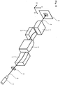
- Fig. 1 is a perspective view of an optical system of an X-ray microscope in Embodiment 1.
- an X-ray 2 emitted from an X-ray source 1 as the origin of the X-ray optical system is incident on a sample holding part 3 holding a sample as a microscopic observation target.
- the X-ray 2 (including light emission and scattering light) having transmitted through the sample holding part 3 is reflected at, in the following order, the reflection concave surface of a concave KB mirror 4, the reflection convex surface of a convex KB mirror 5, the reflection concave surface of a concave KB mirror 6 having a normal orthogonal to the normal of the concave KB mirror 4, and the reflection convex surface of a convex KB mirror 7 having a normal orthogonal to the normal of the convex KB mirror 5.
- the X-ray 2 then arrives at a light receiving part 8 located at a position in an imaging relation to the position of the sample holding part 3.
- a light receiving part 8 located at a position in an imaging relation to the position of the sample holding part 3.
- an elliptical focal position and a hyperbolic focal position coincide with each other.
- light emitted from the reflection concave surface of the concave KB mirror 4 all arrives at the hyperbolic focal position through a total of two times of reflection at the reflection concave surface and the reflection convex surface of the convex KB mirror 5. Accordingly, all optical paths have equal lengths, and thus the X-ray condenses without aberration. The condensing is also possible when the elliptical focal position and the hyperbolic focal position do not coincide with each other.
- the concave KB mirror 4 and the convex KB mirror 5 may be each any other concave or convex surface mirror such as a cylindrical surface mirror, but it is desirable that an elliptical concave surface mirror is used as the concave KB mirror 4 and a hyperbolic concave surface mirror is used as the convex KB mirror 5 as illustrated in Fig. 1 to reduce spherical aberration.
- a "condensing" condition and a "coma suppression" condition are needed for imaging of the X-ray 2 at the light receiving part 8, and the X-ray needs to be reflected an even number of times as illustrated in Fig. 1 to achieve coma suppression.
- the concave KB mirror 4 has elliptical curvature in an X axis direction but no curvature in a Y axis direction, and accordingly has a function to condense an X-ray in the X axis direction.
- the convex KB mirror 5 has hyperbolic curvature in the X axis direction but no curvature in the Y axis direction, and accordingly has a function to change the progressing direction of an X-ray only in the X axis direction.
- the concave KB mirror 6 has elliptical curvature in the Y axis direction but no curvature in the X axis direction, and accordingly has a function to condense an X-ray in the Y axis direction.
- the convex KB mirror 7 has hyperbolic curvature in the Y axis direction but no curvature in the X axis direction, and accordingly has a function to change the progressing direction of an X-ray only in the Y axis direction.
- a magnification in the X axis direction by the concave KB mirror 4 and the convex KB mirror 5 is equal to a magnification in the Y axis direction by the concave KB mirror 6 and the convex KB mirror 7, a sample image without distortion can be obtained on the light receiving part 8.
- a sample image without distortion can be obtained by performing correction through expansion and contraction of a sample image obtained on the light receiving part 8 by an optical system of, for example, visible light or on electronic information, so that the magnification in the X axis direction is equal to the magnification in the Y axis direction.
- Fig. 2 illustrates a geometric pattern diagram (upper part) of the X-ray optical system illustrated in Fig. 1 , and illustrates, for reference, a visible light ray optical system (lower part) having a geometric optical function equivalent to an optical element used in the X-ray optical system.
- the concave KB mirror 6 and the convex KB mirror 7 for condensing in the Y axis direction are not illustrated.
- the X-ray 2 emitted from the X-ray source 1 as the origin of the X-ray optical system is incident on the sample holding part 3 holding a sample as a microscopic observation target.
- the X-ray 2 having transmitted the sample holding part 3 is reflected at the reflection concave surface of the concave KB mirror 4 and the reflection convex surface of the convex KB mirror 5 in this order, and arrives at the light receiving part 8 located at a position in an imaging relation to the position of the sample holding part 3.
- An image of the sample can be determined by specifying the intensity distribution of the X-ray detected at the light receiving part 8.
- the principal plane of a condenser optical system composed of the concave KB mirror 4 and the convex KB mirror 5 is located at a position illustrated with a dotted line in Fig. 2 .
- a distance (front-side focal distance) f between the sample holding part 3 and the principal plane a distance (rear-side focal distance) L between the principal plane and the light receiving part 8
- a magnification Mag of the condenser optical system L / f
- Expression (1) is used in description of an optical system reduction mechanism of the X-ray microscope according to the present invention in Embodiments 3 to 5 to be described later.
- the distance (L + f) between the position of the sample holding part 3 and the position of the light receiving part 8 is preferably 2.5 m or less. This distance is more preferably 2.0 m or less, and further preferably 1.8 m or less.
- the distance f desirably has a smaller value and is preferably 6 mm or more, more preferably 8 mm or more, further preferably 10 mm or more to have an appropriate working distance between the sample holding part 3 and the concave KB mirror 4.
- the value of f has an upper limit of, for example, 40 mm or less, more preferably 20 mm or less, and further preferably 16 mm or less.
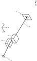
- Fig. 3 is a perspective view of the optical system of the X-ray microscope in Embodiment 2.
- the X-ray microscope in Embodiment 2 is different from the X-ray microscope in Embodiment 1 in that neither concave KB mirror 4 nor convex KB mirror 5 is provided in Embodiment 2.
- the other configuration is same as that of the X-ray microscope in Embodiment 1.
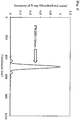
- a point spread function that is distribution of an X-ray intensity at the light receiving part 8 is calculated under a condition that the X-ray source is an ideal point light source.
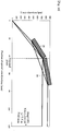
- Fig. 4 illustrates this point spread function.
- the horizontal axis represents a scale (centered at 500 nm) on the Y axis
- the vertical axis represents the X-ray intensity at the light receiving part 8.
- a central peak has a half width (FWHM) of 38 nm, which indicates that a high space resolution is provided.
- FWHM half width
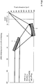
- X-ray optical path simulation was performed, assuming an X-ray microscope in which the concave KB mirror 4 and the convex KB mirror 5 are not provided as in Embodiment 2.
- Fig. 5 illustrates an X-ray optical path up to a place separated by 120 mm from the sample holding part (zero point on the horizontal axis).
- the concave KB mirror 6 and the convex KB mirror 7 are disposed in this order halfway through the X-ray optical path.
- Fig. 6 illustrates an X-ray optical path of an optical system in which two concave KB mirrors (a concave KB mirror 19 and a concave KB mirror 20) as in a conventional case are disposed, in place of the concave KB mirror 6 and the convex KB mirror 7, at positions same as the positions of the concave KB mirror 6 and the convex KB mirror 7 described in Embodiment 3 in the direction of the optical axis.
- two concave KB mirrors a concave KB mirror 19 and a concave KB mirror 20
- X-ray optical path simulation was performed, assuming an X-ray microscope in which the concave KB mirror 4 and the convex KB mirror 5 are not provided as in Embodiment 2.
- Fig. 7 illustrates an X-ray optical path up to a place separated by 120 mm from the sample holding part (zero point on the horizontal axis).
- the concave KB mirror 6 and the convex KB mirror 7 are disposed in this order at a position different from the example of Embodiment 3 and halfway through the X-ray optical path.
- Fig. 8 illustrates an X-ray optical path of an optical system in which two concave KB mirrors (the concave KB mirror 19 and the concave KB mirror 20) as in a conventional case are disposed, in place of the concave KB mirror 6 and the convex KB mirror 7, at positions same as the positions of the concave KB mirror 6 and the convex KB mirror 7 described in Embodiment 4 in the direction of the optical axis.
- X-ray optical path simulation was performed, assuming an X-ray microscope in which the concave KB mirror 4 and the convex KB mirror 5 are not provided as in Embodiment 2.
- Fig. 9 illustrates an X-ray optical path up to a place separated by 120 mm from the sample holding part (zero point on the horizontal axis).
- the concave KB mirror 6 and the convex KB mirror 7 are disposed in this order at a position different from the examples of Embodiments 3 and 4 and halfway through the X-ray optical path.
- Fig. 10 illustrates an X-ray optical path of an optical system in which two concave KB mirrors (the concave KB mirror 19 and the concave KB mirror 20) as in a conventional case are disposed, in place of the concave KB mirror 6 and the convex KB mirror 7, at positions same as the positions of the concave KB mirror 6 and the convex KB mirror 7 described in Embodiment 5 in the direction of the optical axis.
- two concave KB mirrors the concave KB mirror 19 and the concave KB mirror 20
- Fig. 11 is a perspective view of an optical system of an X-ray microscope in Embodiment 6 of the present invention.
- the X-ray microscope in Embodiment 6 is different from the X-ray microscope in Embodiment 1 in that a first concave KB mirror 21 and a second concave KB mirror 22 are used for condensing in the X axis direction in Embodiment 6, whereas the concave KB mirror 4 and the convex KB mirror 5 are used for condensing in the X axis direction in Embodiment 1.
- the other configuration is same as that of the X-ray microscope in Embodiment 1.
- the first concave KB mirror 21 and the second concave KB mirror 22 each have curvature in the X axis direction but no curvature in the Y axis direction, and accordingly has a function to condense an X-ray in the X axis direction.
- the concave KB mirror 6 has curvature in the Y axis direction but no curvature in the X axis direction, and accordingly has a function to condense an X-ray in the Y axis direction.
- the convex KB mirror 7 has curvature in the Y axis direction but no curvature in the X axis direction, and accordingly has a function to change the progressing direction of an X-ray only in the Y axis direction.
- Embodiment 1 The X-ray microscope described above in Embodiment 1 has a high effect of increasing the magnification for a sample, but the magnification is too high when a mirror has a large NA.
- a mirror in Embodiment 1, the concave KB mirror 4 and the convex KB mirror 5 as a pair of mirrors for condensing in the X axis direction
- the magnification is too high.
- longitudinal and transverse (in the X axis direction and the Y axis direction) magnifications are desirably equal to each other.
- the reflection concave surface of the first concave KB mirror 21 located at a place closer to the sample holding part than the second concave KB mirror 22 includes a hyperbolic curve
- the reflection concave surface of the second concave KB mirror 22 includes an ellipse.
- the elliptical focal position of the second concave KB mirror 22 and the hyperbolic focal position of the first concave KB mirror 21 coincide with each other, and thus, similarly to Embodiment 1, X-rays emitted from a single point on a sample condense to a single point on an image plane.
- all optical paths from the sample to the image plane have equal lengths, and accordingly, a sharp image can be obtained.
- Fig. 12 illustrates an X-ray optical path (X-axis projection) near the first concave KB mirror 21 and the second concave KB mirror 22 of the X-ray microscope in Embodiment 6.
- Fig. 13 illustrates an X-ray optical path (Y-axis projection) near the concave KB mirror 6 and the convex KB mirror 7 of the X-ray microscope in Embodiment 6.
- the X-ray microscope has condensing performance as listed in Table 1 below.
- each position of the principal plane of the lens system is illustrated with a dotted line.
- Comparison of Fig. 5 (Embodiment 3) and Fig. 6 (Comparative Embodiment 1) indicates that the position of the principal plane of a lens is separated from the sample holding part by 70 mm (refer to the value of f in Fig. 6 ) in Comparative Embodiment 1, but the position of the principal plane of a lens is separated from the sample holding part by 12 mm (refer to the value of f in Fig. 5 ) in Embodiment 3, which is an extremely reduced value.
- the value of f is small, designing with a reduced value of L is possible on an assumption that the magnification Mag of the microscope is approximately maintained, as indicated by the above-described Expression (1).
- the value of L is 12.6 m in the example illustrated in Fig. 6 , but the value of L is 2.0 m in the example illustrated in Fig. 5 , which is an extremely reduced value.
- the X-ray microscope can be designed to be small enough to be brought into a laboratory.
- Fig. 7 Embodiment 4
- Fig. 8 Comparative Embodiment 2
- the value of f is reduced from 22 mm to 4.0 mm and the position of the principal plane is located closer to the position of the sample holding part 3.
- the value of L is 3.8 m in the example illustrated in Fig. 8
- the value of L is 0.7 m in the example illustrated in Fig. 7 , which is an extremely reduced value.
- the X-ray microscope can be designed to be small enough to be brought into a laboratory.
- Fig. 9 Embodiment 5
- Fig. 10 Comparative Embodiment 3
- the value of f is reduced from 43 mm to 11 mm and the position of the principal plane is located closer to the position of the sample holding part 3.
- the value of L is 7.7 m in the example illustrated in Fig. 10
- the value of L is 2.0 m in the example illustrated in Fig. 9 , which is an extremely reduced value.
- the X-ray microscope can be designed to be small enough to be brought into a laboratory.
- Embodiments 3 to 5 describe above effects of the present invention in an example with a one-dimensional condensing optical system.
- a pair of a concave KB mirror and a convex KB mirror is used in each of the X axis direction and the Y axis direction to achieve two-dimensional condensing.
- a two-dimensional condenser optical system can be formed without interference between the mirrors.
- the rear-side focal distance (the value of L) of the mirror system in Fig. 7 is 0.7 m.
- These rear-side focal distances can be made equal to each other by adjusting, for example, the NA value and magnification of the mirror system in Fig. 7 .
- the magnification in the X direction and the magnification in the Y direction are different from each other in some cases, but distortion of the image plane can be optically or electrically corrected as described in the above-described embodiment.
- an extremely small X-ray microscope including a two-dimensional condenser optical system, the rear-side focal distance of which is 2.0 m, can be achieved.
- Embodiment 6 is an X-ray microscope in which the concave KB mirror 6 and the convex KB mirror 7 are used for condensing in the Y axis direction, and the first concave KB mirror 21 and the second concave KB mirror 22 are used for condensing in the X axis direction.
- Table 1 since the first concave KB mirror 21 and the second concave KB mirror 22, which are located close to the position of the sample holding part 3, each has a concave reflection surface in the X-ray microscope according to the present embodiment, the position of the principal plane can be separated from a sample, and the magnification in the X axis direction can be reduced.
- the distance (L + f) between the position of the sample holding part 3 and the position of the light receiving part 8 is 3127 mm, which indicates downsizing of the entire device.
- the principal plane needs to be separated from the position of the sample holding part 3 to obtain a certain magnification in a conventional X-ray microscope, but in the X-ray microscope according to the present invention, the position of the principal plane is located largely closer to the position of the sample holding part 3, and accordingly, an X-ray microscope with the value of L reduced enough to be brought into a laboratory can be provided.
- the X-ray microscope according to the present invention can have a reduced rear-side focal distance of the optical system while the magnification is maintained.
- the present invention allows a conventional X-ray microscope not having a widely usable size, in other words, a size of which cannot be brought into a room, to have a widely usable small size, and has high industrial applicability by the use of an X-ray microscope in various scientific fields.
Landscapes
- Physics & Mathematics (AREA)
- Engineering & Computer Science (AREA)
- General Engineering & Computer Science (AREA)
- High Energy & Nuclear Physics (AREA)
- Spectroscopy & Molecular Physics (AREA)
- Analysing Materials By The Use Of Radiation (AREA)
Abstract
Description
- The present invention relates to an X-ray microscope, and particularly relates to an X-ray microscope using a Kirkpatrick-Baez mirror.
- An X-ray microscope is an imaging optical system using electromagnetic wave having an extremely short wavelength, and has, in principle, a sub-nm high resolution significantly higher than that of an optical microscope. The high transmission power of an X-ray allows observation of a three-dimensional tomographic image of a thick sample, which is difficult with a transmissive electron microscope. In addition, basically, the X-ray microscope does not need vacuum formation, and thus, is suitable for observation in an environment (for example, an atmosphere of water solution and gas) in which in-situ measurement is required. In addition, not only electron density distribution but also a local coupling state and element distribution can be acquired by combining X-ray analysis technologies such as fluorescence X-ray analysis and X-ray absorption spectroscopy. The X-ray microscope, which has such various advantages, is expected to be used in various scientific fields.
- Examples of promised candidates for an imaging element in the X-ray microscope include a Fresnel zone plate, an X-ray refraction lens, a Kirkpatrick-Baez (KB) mirror, and a Wolter mirror. The Fresnel zone plate and the X-ray refraction lens can be sufficiently accurately manufactured to achieve a sub-50-nm resolution. However, the Fresnel zone plate and the refraction lens are not suitable for multicolor imaging because of chromatic aberration occurring due to diffraction. The KB mirror employs total reflection and thus does not suffer chromatic aberration. However, it is difficult to satisfy the Abbe sine condition with single reflection in an grazing-incidence optical system such as the KB mirror, and accordingly, coma occurs, which leads to decrease of the resolution and the field of view (FOV). The Wolter mirror, which solves chromatic aberration and coma, is an excellent X-ray imaging system.
- However, even when the state-of-the-art ultraprecise fabrication technology is used, it is difficult to fabricate the Wolter mirror at a shaping accuracy (order of 1 nm) necessary for achieving a resolution at diffraction limit because the Wolter mirror has a mirror surface formed of an ellipsoid surface and a hyperboloid surface disposed on a tubular inner surface. Thus, wavefront aberration in the Wolter mirror due to shaping error is a serious problem that currently cannot be avoided, and there has been no report so far that the mirror is produced at a shaping accuracy sufficient to achieve high resolution performance (100 nm or less).
- Examples of an X-ray optical system using the KB mirror include an optical system (Advanced KB mirror) using four grazing-incidence total reflection X-ray mirrors of a horizontal elliptical mirror, a vertical elliptical mirror, a horizontal hyperbolic mirror, and a vertical hyperbolic mirror as disclosed in
Patent Document 1. In this optical system, a horizontal stage and a vertical stage are disposed along the optical axis direction of an X-ray, the horizontal elliptical mirror and the horizontal hyperbolic mirror are provided on the horizontal stage in a finely adjustable manner, and the vertical elliptical mirror and the vertical hyperbolic mirror are provided on the vertical stage in a finely adjustable manner. The optical system includes a mirror manipulator that sets a front-rear positional relation between the horizontal elliptical mirror and the horizontal hyperbolic mirror and a front-rear positional relation between the vertical elliptical mirror and the vertical hyperbolic mirror to be same in the optical axis direction, and an off-line alignment monitoring means that provides a reference for fine adjustment so that the horizontal postures of the horizontal elliptical mirror and the horizontal hyperbolic mirror and the vertical postures of the vertical elliptical mirror and the vertical hyperbolic mirror are ideal within the margin of error. - The X-ray optical system disclosed in
Patent Document 1 achieves scaling up and down of an X-ray of 2 keV or higher at a high resolution of 200 nm or less without aberration. - Patent Document 1:
JP-A-2013-221874 - However, a Kirkpatrick-Baez (KB) mirror type X-ray microscope allows various kinds of improvement. Unless a problem that cannot be ignored when it is assumed that the X-ray microscope is widely spread and used in various scientific fields is solved, in other words, unless the length of an X-ray microscope device is within two to three meters, it is needed to prepare a facility, for example, a corridor width and an entrance width of which are specially designed to be large to convey the X-ray microscope. When the X-ray microscope is larger than this size, wide use in existing research facilities or the like is hampered for the X-ray microscope even with excellent performance such as a resolution. The present invention is intended to provide an X-ray microscope that has a size small enough to be brought into a room and can be widely used.
- An X-ray microscope according to the present invention which solves the above problem comprises an X-ray source, a sample holding part, a Kirkpatrick-Baez mirror having a reflection concave surface (that is hereinafter referred to as a "concave KB mirror"), a Kirkpatrick-Baez mirror having a reflection convex surface (that is hereinafter referred to as a "convex KB mirror"), and a light receiving part located at a position in an imaging relation to a position of the sample holding part in this order.
- Although described later in detail, in the X-ray microscope according to the present invention, the concave KB mirror is disposed on a side closer to the sample holding part, and the convex KB mirror is disposed on a side closer to the light receiving part. Thus, the distance (front-side focal distance) between the position of the principal plane of a lens system and the sample holding part can be reduced as compared to conventional cases. Accordingly, it is possible to achieve an X-ray microscope in which the rear-side focal distance as the distance between the position of the principal plane of the lens system and the light receiving part can be significantly shortened when it is assumed that the magnification is approximately same as that of a conventional optical system, and that has a length of two to three meters or less.
- In the X-ray microscope, it is preferred that the reflection concave surface of the concave KB mirror includes an elliptical curve, and the sample holding part is located at a focal position of the ellipse.
- In the X-ray microscope, it is preferred that the reflection convex surface of the convex KB mirror includes one curved line of a hyperbolic curve that is composed of the one curved line and the other curved line, and the light receiving part is located at a focal position of the other curved line side of focal positions of the hyperbolic curve.
- In the X-ray microscope, it is preferred that a distance between the concave KB mirror and the light receiving part is longer than a distance between the convex KB mirror and the light receiving part.
- In the X-ray microscope, it is preferred that a principal plane of an imaging system including the convex KB mirror and the concave KB mirror is located between the sample holding part and the concave KB mirror.
- In the X-ray microscope, it is preferred that a distance between the position of the sample holding part and the position of the light receiving part is 2.5 m or less.
- In the X-ray microscope, it is preferred that at least the two convex KB mirrors and at least the two concave KB mirrors are provided, a normal of one of the convex KB mirrors and a normal of the other of the convex KB mirrors are non-parallel to each other, and a normal of one of the concave KB mirrors and a normal of the other of the concave KB mirrors are non-parallel to each other.
- In the X-ray microscope, it is preferred that a shortest distance between the sample holding part and the concave KB mirror is 6 mm or more.
- In the X-ray microscope, it is preferred that at least one of the convex KB mirror and the concave KB mirror is installed so as to be movable in an optical axis direction.
- In the X-ray microscope, it is preferred that a first concave KB mirror and a second concave KB mirror are provided between the sample holding part and the concave KB mirror, a normal of the concave KB mirror and a normal of the first concave KB mirror are non-parallel to each other, and a normal of the convex KB mirror and a normal of the second concave KB mirror are non-parallel to each other.
- In the X-ray microscope, it is preferred that the first concave KB mirror is located closer to the sample holding part than the second concave KB mirror, a reflection concave surface of the first concave KB mirror includes a hyperbolic curve, and a reflection concave surface of the second concave KB mirror includes an elliptical curve.
- An X-ray microscope according to the present invention includes an X-ray source, a sample holding part, a concave KB mirror, a convex KB mirror, and a light receiving part located at a position in an imaging relation to the position of the sample holding part in this order along an optical axis, and thus can have a reduced rear-side focal distance of an optical system while the magnification is maintained. Accordingly, a conventional X-ray microscope can be made to have a size that can be brought into a room, in other words, a widely usable size, thereby achieving high industrial applicability due to increased use of X-ray microscopes in various scientific fields.
-
-
Fig. 1 is a perspective view of an optical system of an X-ray microscope inEmbodiment 1 of the present invention. -
Fig. 2 illustrates a geometric pattern diagram (upper part) of an X-ray optical system illustrated inFig. 1 , and illustrates, for reference, a visible light ray optical system (lower part) having a geometric optical function equivalent to an optical element used in the X-ray optical system. -
Fig. 3 is a perspective view of the optical system of the X-ray microscope inEmbodiment 2 of the present invention. -
Fig. 4 illustrates a point spread function by the X-ray microscope inEmbodiment 2. -
Fig. 5 illustrates an X-ray optical path of the X-ray microscope inEmbodiment 3. -
Fig. 6 illustrates an X-ray optical path of the X-ray microscope inComparative Embodiment 1. -
Fig. 7 illustrates an X-ray optical path of the X-ray microscope inEmbodiment 4. -
Fig. 8 illustrates an X-ray optical path of the X-ray microscope inComparative Embodiment 2. -
Fig. 9 illustrates an X-ray optical path of the X-ray microscope inEmbodiment 5. -
Fig. 10 illustrates an X-ray optical path of the X-ray microscope inComparative Embodiment 3. -
Fig. 11 is a perspective view of the optical system of the X-ray microscope inEmbodiment 6 of the present invention. -
Fig. 12 illustrates an X-ray optical path (X-axis projection) of the X-ray microscope inEmbodiment 6. -
Fig. 13 illustrates an X-ray optical path (Y-axis projection) of the X-ray microscope inEmbodiment 6. - An X-ray microscope in an embodiment of the present invention will be described below. An X-ray microscope according to the present invention includes at least one of each of an X-ray source, a sample holding part, a concave KB mirror, a convex KB mirror, and a light receiving part located at a position in an imaging relation to the position of the sample holding part in this order along an optical axis. With this configuration, the rear-side focal distance of an optical system can be reduced while the magnification of the X-ray microscope is held. The following sequentially describes the X-ray source, the sample holding part, the concave KB mirror, the convex KB mirror, and the light receiving part, which are basic requirements of the present invention.
- Any device having a function to emit an X-ray is applicable, but a small X-ray tube for laboratory usage is preferably used, and alternatively, a synchrotron radiation facility (such as SPring-8) can be used. Similarly to a normal optical microscope using a visible light ray, the X-ray microscope preferably uses Kohler illumination or critical illumination, and it is desirable to use a light source capable of achieving these illuminations. It is difficult to perform complicated Kohler illumination in an X-ray region, and thus, typically, critical illumination is performed, or an X-ray approximately having the range of the field of view is emitted as appropriate. Accordingly, a sample as an observation target can be irradiated with an X-ray having uniform intensity, and clear imaging with little blurring can be obtained. The energy of an X-ray is not particularly limited, and a soft X-ray, an X-ray, and a hard X-ray can be used, but it is desirable to use an X-ray or a hard X-ray having energy of 2 keV or higher to obtain a high resolution of 200 nm or less.
- The sample holding part may be any instrument having a function to hold a sample as an observation target on the optical path of an X-ray. The sample holding part may be, for example, a table on which a sample is simply placed, two dielectric flat plates for sandwiching a sample therebetween, a dielectric single-plate for fixing a sample, a frame for hanging a sample, or a container for holding a liquid sample. An instrument having any configuration having a function to hold a sample on the optical path of an X-ray may be used as the sample holding part. The material of the sample holding part is not particularly limited, but it is desirable to use a material that transmits an X-ray when the X-ray is directly incident on the sample holding part. It is also desirable to select a material to which accumulation of electric charge due to X-ray irradiation is unlikely to occur.
- The reflection surface of the above-described Wolter mirror is formed by a rotational locus of a curved line, but, a KB mirror used in the present invention is a one-dimensional condensing mirror having curvature only in one direction. The KB mirror has a shape close to a flat plate, and thus it is easier to fabricate a surface thereof as compared to the Wolter mirror. The incident angle (angle between the surface of the KB mirror and the optical axis) of an X-ray by the KB mirror is typically several milliradian approximately, and 80 to 90% approximately of an incident X-ray is reflected. When the incident angle is large, a larger fraction of the X-ray transmits the KB mirror.
- It is sufficient that a part of the entire of one KB mirror where the reflection surface is formed in a curved surface extends across a range irradiated with an X-ray. However, it is preferable to form a mirror shape continuously for a long interval in the other direction orthogonal to the one direction in which the KB mirror has the curvature so that a surface not irradiated with an X-ray can be used by sliding the KB mirror when the irradiated part degrades while the KB mirror is used. For example, the length of the mirror formation interval in the other direction is preferably two to five times, more preferably two to ten times, further preferably two to fifteen times larger than the length of a mirror formation interval in the one direction.
- The accuracy of the shape (JIS B0182 Basics 306) of the reflection surface of the KB mirror is preferably 5 nm or less, more preferably 3 nm or less, further preferably 1 nm or less. The surface roughness (JIS B0091: Rms) of the reflection surface is preferably 0.5 nm or less, more preferably 0.3 nm or less, further preferably 0.1 nm or less.
- Typically, the term "KB mirror" indicates a pair of mirrors, the directions (for example, X and Y directions) of the normals of which are orthogonal to each other. However, a "KB mirror" used herein indicates a single (one) X-ray mirror. Thus, the X-ray microscope according to the present invention includes a case in which a single mirror is used, and also includes a case in which a plurality of mirrors, the directions of the normals of which are different from one another are included. In the case in which a plurality of mirrors, the directions of the normals of which are different from each other are included, the normals are desirably angled from each other at a value by dividing 360° by "the number of mirrors" × 2. For example, when imaging is achieved by using two KB mirrors, the normals of the mirrors are preferably angled at 360°/(2 × 2) = 90° from each other.
- The X-ray microscope according to the present invention is applicable to a case in which only one pair of one convex KB mirror and one concave KB mirror is included, and also applicable to a case in which a plurality of pairs of a convex KB mirror and a concave KB mirror are used. The X-ray microscope according to the present invention only needs to include at least one pair of one convex KB mirror and one concave KB mirror, and may additionally include one or a plurality of pairs of a first concave KB mirror and a second concave KB mirror.
- As described above, the X-ray microscope according to the present invention includes at least the concave KB mirror and the convex KB mirror. Among these KB mirrors, the concave KB mirror is disposed on a side closer to the sample holding part. The curvature of a reflection concave surface of the concave KB mirror and the curvature distribution thereof are not particularly limited, but the reflection concave surface may have, for example, an arc shape, an elliptical shape, a hyperbolic shape, or a parabolic shape. Among these shapes, it is preferable to have the elliptical shape to obtain a favorable imaging characteristic. The sample holding part is preferably disposed at the focal position of an elliptical mirror, in particular, the position of a focal position close to the sample holding part.
- As described above, the X-ray microscope according to the present invention includes at least the concave KB mirror and the convex KB mirror, and the convex KB mirror is disposed on the side closer to the light receiving part. A sectional shape of a reflection convex surface is not particularly limited, but may be, for example, an arc shape, an elliptical shape, a hyperbolic shape, or a parabolic shape. Among these shapes, it is desirable to have the hyperbolic shape to obtain a favorable imaging characteristic. The reflection convex surface includes one curved line of a hyperbolic curve that is composed of the one curved line and the other curved line, and the light receiving part is preferably located at one of the focal positions of the hyperbolic curve, which is closer to the other curved line.
- The light receiving part in the present invention is a member configured to receive an imaged X-ray image through the convex KB mirror and the concave KB mirror of the X-ray microscope according to the present invention. The receiving member is typically an array sensor, and preferably a two-dimensional array sensor. Examples of the two-dimensional array sensor include a CCD element and a CMOS element. The pixel pitch of the array sensor is preferably 20 µm or less, more preferably 9 µm or less, further preferably 3 µm or less to clearly receive the imaged X-ray image.
- The light receiving part may be a diffusion plate configured to convert a received X-ray into light having a wavelength longer than that of the X-ray, typically an ultraviolet ray or a visible light ray. Examples of the diffusion plate include a substrate containing a fluorescence material. X-ray imaging at the light receiving part can be acquired by imaging, through a visible light ray lens, light diffused through the diffusion plate and performing image capturing through an array sensor, preferably a two-dimensional array sensor such as a CCD element or a CMOS element.
- This application claims the benefit of the priority date of Japanese patent application No.
2015-188850 filed on September 25, 2015 2015-188850 filed on September 25, 2015 - The following describes an X-ray microscope in
Embodiment 1 of the present invention. -
Fig. 1 is a perspective view of an optical system of an X-ray microscope inEmbodiment 1. InFig. 1 , anX-ray 2 emitted from anX-ray source 1 as the origin of the X-ray optical system is incident on asample holding part 3 holding a sample as a microscopic observation target. The X-ray 2 (including light emission and scattering light) having transmitted through thesample holding part 3 is reflected at, in the following order, the reflection concave surface of aconcave KB mirror 4, the reflection convex surface of aconvex KB mirror 5, the reflection concave surface of aconcave KB mirror 6 having a normal orthogonal to the normal of theconcave KB mirror 4, and the reflection convex surface of aconvex KB mirror 7 having a normal orthogonal to the normal of theconvex KB mirror 5. TheX-ray 2 then arrives at alight receiving part 8 located at a position in an imaging relation to the position of thesample holding part 3. In the example illustrated inFig. 1 , an elliptical focal position and a hyperbolic focal position coincide with each other. Thus, light emitted from the reflection concave surface of theconcave KB mirror 4 all arrives at the hyperbolic focal position through a total of two times of reflection at the reflection concave surface and the reflection convex surface of theconvex KB mirror 5. Accordingly, all optical paths have equal lengths, and thus the X-ray condenses without aberration. The condensing is also possible when the elliptical focal position and the hyperbolic focal position do not coincide with each other. Theconcave KB mirror 4 and theconvex KB mirror 5 may be each any other concave or convex surface mirror such as a cylindrical surface mirror, but it is desirable that an elliptical concave surface mirror is used as theconcave KB mirror 4 and a hyperbolic concave surface mirror is used as theconvex KB mirror 5 as illustrated inFig. 1 to reduce spherical aberration. A "condensing" condition and a "coma suppression" condition are needed for imaging of theX-ray 2 at thelight receiving part 8, and the X-ray needs to be reflected an even number of times as illustrated inFig. 1 to achieve coma suppression. - The
concave KB mirror 4 has elliptical curvature in an X axis direction but no curvature in a Y axis direction, and accordingly has a function to condense an X-ray in the X axis direction. Theconvex KB mirror 5 has hyperbolic curvature in the X axis direction but no curvature in the Y axis direction, and accordingly has a function to change the progressing direction of an X-ray only in the X axis direction. Theconcave KB mirror 6 has elliptical curvature in the Y axis direction but no curvature in the X axis direction, and accordingly has a function to condense an X-ray in the Y axis direction. Theconvex KB mirror 7 has hyperbolic curvature in the Y axis direction but no curvature in the X axis direction, and accordingly has a function to change the progressing direction of an X-ray only in the Y axis direction. When a magnification in the X axis direction by theconcave KB mirror 4 and theconvex KB mirror 5 is equal to a magnification in the Y axis direction by theconcave KB mirror 6 and theconvex KB mirror 7, a sample image without distortion can be obtained on thelight receiving part 8. - When the magnification in the X axis direction is not equal to the magnification in the Y axis direction, a sample image without distortion can be obtained by performing correction through expansion and contraction of a sample image obtained on the
light receiving part 8 by an optical system of, for example, visible light or on electronic information, so that the magnification in the X axis direction is equal to the magnification in the Y axis direction. -
Fig. 2 illustrates a geometric pattern diagram (upper part) of the X-ray optical system illustrated inFig. 1 , and illustrates, for reference, a visible light ray optical system (lower part) having a geometric optical function equivalent to an optical element used in the X-ray optical system. In the upper part ofFig. 2 , to facilitate understanding, theconcave KB mirror 6 and theconvex KB mirror 7 for condensing in the Y axis direction are not illustrated. In the upper part ofFig. 2 , theX-ray 2 emitted from theX-ray source 1 as the origin of the X-ray optical system is incident on thesample holding part 3 holding a sample as a microscopic observation target. TheX-ray 2 having transmitted thesample holding part 3 is reflected at the reflection concave surface of theconcave KB mirror 4 and the reflection convex surface of theconvex KB mirror 5 in this order, and arrives at thelight receiving part 8 located at a position in an imaging relation to the position of thesample holding part 3. An image of the sample can be determined by specifying the intensity distribution of the X-ray detected at thelight receiving part 8. - The principal plane of a condenser optical system composed of the
concave KB mirror 4 and theconvex KB mirror 5 is located at a position illustrated with a dotted line inFig. 2 . There is a relation indicated by Expression (1) below among a distance (front-side focal distance) f between thesample holding part 3 and the principal plane, a distance (rear-side focal distance) L between the principal plane and thelight receiving part 8, and a magnification Mag of the condenser optical system.
- Expression (1) is used in description of an optical system reduction mechanism of the X-ray microscope according to the present invention in
Embodiments 3 to 5 to be described later. The distance (L + f) between the position of thesample holding part 3 and the position of thelight receiving part 8 is preferably 2.5 m or less. This distance is more preferably 2.0 m or less, and further preferably 1.8 m or less. To achieve this, the distance f desirably has a smaller value and is preferably 6 mm or more, more preferably 8 mm or more, further preferably 10 mm or more to have an appropriate working distance between thesample holding part 3 and theconcave KB mirror 4. The value of f has an upper limit of, for example, 40 mm or less, more preferably 20 mm or less, and further preferably 16 mm or less. -
Fig. 3 is a perspective view of the optical system of the X-ray microscope inEmbodiment 2. The X-ray microscope inEmbodiment 2 is different from the X-ray microscope inEmbodiment 1 in that neitherconcave KB mirror 4 norconvex KB mirror 5 is provided inEmbodiment 2. The other configuration is same as that of the X-ray microscope inEmbodiment 1. - To evaluate an imaging characteristic of the X-ray microscope in
Embodiment 2, a point spread function (PSF) that is distribution of an X-ray intensity at thelight receiving part 8 is calculated under a condition that the X-ray source is an ideal point light source.Fig. 4 illustrates this point spread function. InFig. 4 , the horizontal axis represents a scale (centered at 500 nm) on the Y axis, and the vertical axis represents the X-ray intensity at thelight receiving part 8. As illustrated inFig. 4 , a central peak has a half width (FWHM) of 38 nm, which indicates that a high space resolution is provided. Detailed conditions used in the calculation are as follows. - Mag: 181 times
- L: 0.7 m
- f: 4.0 mm
- NA of a lens system of the
concave KB mirror 6 and the convex KB mirror 7: 1.3 × 10⁻³ - X-ray optical path simulation was performed, assuming an X-ray microscope in which the
concave KB mirror 4 and theconvex KB mirror 5 are not provided as inEmbodiment 2.Fig. 5 illustrates an X-ray optical path up to a place separated by 120 mm from the sample holding part (zero point on the horizontal axis). Theconcave KB mirror 6 and theconvex KB mirror 7 are disposed in this order halfway through the X-ray optical path. -
Fig. 6 illustrates an X-ray optical path of an optical system in which two concave KB mirrors (aconcave KB mirror 19 and a concave KB mirror 20) as in a conventional case are disposed, in place of theconcave KB mirror 6 and theconvex KB mirror 7, at positions same as the positions of theconcave KB mirror 6 and theconvex KB mirror 7 described inEmbodiment 3 in the direction of the optical axis. - X-ray optical path simulation was performed, assuming an X-ray microscope in which the
concave KB mirror 4 and theconvex KB mirror 5 are not provided as inEmbodiment 2.Fig. 7 illustrates an X-ray optical path up to a place separated by 120 mm from the sample holding part (zero point on the horizontal axis). Theconcave KB mirror 6 and theconvex KB mirror 7 are disposed in this order at a position different from the example ofEmbodiment 3 and halfway through the X-ray optical path. -
Fig. 8 illustrates an X-ray optical path of an optical system in which two concave KB mirrors (theconcave KB mirror 19 and the concave KB mirror 20) as in a conventional case are disposed, in place of theconcave KB mirror 6 and theconvex KB mirror 7, at positions same as the positions of theconcave KB mirror 6 and theconvex KB mirror 7 described inEmbodiment 4 in the direction of the optical axis. - X-ray optical path simulation was performed, assuming an X-ray microscope in which the
concave KB mirror 4 and theconvex KB mirror 5 are not provided as inEmbodiment 2.Fig. 9 illustrates an X-ray optical path up to a place separated by 120 mm from the sample holding part (zero point on the horizontal axis). Theconcave KB mirror 6 and theconvex KB mirror 7 are disposed in this order at a position different from the examples ofEmbodiments -
Fig. 10 illustrates an X-ray optical path of an optical system in which two concave KB mirrors (theconcave KB mirror 19 and the concave KB mirror 20) as in a conventional case are disposed, in place of theconcave KB mirror 6 and theconvex KB mirror 7, at positions same as the positions of theconcave KB mirror 6 and theconvex KB mirror 7 described inEmbodiment 5 in the direction of the optical axis. -
Fig. 11 is a perspective view of an optical system of an X-ray microscope inEmbodiment 6 of the present invention. The X-ray microscope inEmbodiment 6 is different from the X-ray microscope inEmbodiment 1 in that a firstconcave KB mirror 21 and a secondconcave KB mirror 22 are used for condensing in the X axis direction inEmbodiment 6, whereas theconcave KB mirror 4 and theconvex KB mirror 5 are used for condensing in the X axis direction inEmbodiment 1. The other configuration is same as that of the X-ray microscope inEmbodiment 1. - The first
concave KB mirror 21 and the secondconcave KB mirror 22 each have curvature in the X axis direction but no curvature in the Y axis direction, and accordingly has a function to condense an X-ray in the X axis direction. - The
concave KB mirror 6 has curvature in the Y axis direction but no curvature in the X axis direction, and accordingly has a function to condense an X-ray in the Y axis direction. Theconvex KB mirror 7 has curvature in the Y axis direction but no curvature in the X axis direction, and accordingly has a function to change the progressing direction of an X-ray only in the Y axis direction. - The X-ray microscope described above in
Embodiment 1 has a high effect of increasing the magnification for a sample, but the magnification is too high when a mirror has a large NA. In particular, a mirror (inEmbodiment 1, theconcave KB mirror 4 and theconvex KB mirror 5 as a pair of mirrors for condensing in the X axis direction) close to a sample has a large NA, and thus the magnification is too high. In practical use, longitudinal and transverse (in the X axis direction and the Y axis direction) magnifications are desirably equal to each other. In the X-ray microscope inEmbodiment 6, when a pair of mirrors (the firstconcave KB mirror 21 and the second concave KB mirror 22) on a side closer to a sample are both concave mirrors, an appropriate magnification can be obtained in the X axis direction so that the longitudinal and transverse magnifications of the X-ray microscope are adjusted to be equal to each other. - More preferably, it is desirable that the reflection concave surface of the first
concave KB mirror 21 located at a place closer to the sample holding part than the secondconcave KB mirror 22 includes a hyperbolic curve, and the reflection concave surface of the secondconcave KB mirror 22 includes an ellipse. In the example illustrated inFig. 11 , the elliptical focal position of the secondconcave KB mirror 22 and the hyperbolic focal position of the firstconcave KB mirror 21 coincide with each other, and thus, similarly toEmbodiment 1, X-rays emitted from a single point on a sample condense to a single point on an image plane. Thus, all optical paths from the sample to the image plane have equal lengths, and accordingly, a sharp image can be obtained. -
Fig. 12 illustrates an X-ray optical path (X-axis projection) near the firstconcave KB mirror 21 and the secondconcave KB mirror 22 of the X-ray microscope inEmbodiment 6.Fig. 13 illustrates an X-ray optical path (Y-axis projection) near theconcave KB mirror 6 and theconvex KB mirror 7 of the X-ray microscope inEmbodiment 6. The X-ray microscope has condensing performance as listed in Table 1 below.[Table 1] First concave KB mirror 21Second concave KB mirror 21Concave KB mirror 6Convex KB mirror 7Curve Type hyperbolic elliptical elliptical hyperbolic Equation x2/a2-y2/b2=1 x2/a2+y2/b2=1 x2/a2+y2/b2=1 x2/a2-y2/b2= 1 a 0.095 m 1.573 m 0.0845 m 1.479 m b 4.075×10⁻⁴m 5.619×10⁻³m 1.254×10⁻³m 1.853×10⁻³m Prospective angle 16.86 mrad 14.50 mrad 15.68 mrad 5.22 mrad NA 5.057×10⁻³ 5.043×10⁻³ Focal distance f 21.47 mm 22.12 mm Magnification 144.6 times 140.4 times L+f 3127 mm - In
Figs. 5 to 10 , each position of the principal plane of the lens system is illustrated with a dotted line. - Comparison of
Fig. 5 (Embodiment 3) andFig. 6 (Comparative Embodiment 1) indicates that the position of the principal plane of a lens is separated from the sample holding part by 70 mm (refer to the value of f inFig. 6 ) inComparative Embodiment 1, but the position of the principal plane of a lens is separated from the sample holding part by 12 mm (refer to the value of f inFig. 5 ) inEmbodiment 3, which is an extremely reduced value. When the value of f is small, designing with a reduced value of L is possible on an assumption that the magnification Mag of the microscope is approximately maintained, as indicated by the above-described Expression (1). The value of L is 12.6 m in the example illustrated inFig. 6 , but the value of L is 2.0 m in the example illustrated inFig. 5 , which is an extremely reduced value. Thus, the X-ray microscope can be designed to be small enough to be brought into a laboratory. - Similarly, comparison of
Fig. 7 (Embodiment 4) andFig. 8 (Comparative Embodiment 2) indicates that the value of f is reduced from 22 mm to 4.0 mm and the position of the principal plane is located closer to the position of thesample holding part 3. Accordingly, the value of L is 3.8 m in the example illustrated inFig. 8 , but the value of L is 0.7 m in the example illustrated inFig. 7 , which is an extremely reduced value. Thus, the X-ray microscope can be designed to be small enough to be brought into a laboratory. - Similarly, comparison of
Fig. 9 (Embodiment 5) andFig. 10 (Comparative Embodiment 3) indicates that the value of f is reduced from 43 mm to 11 mm and the position of the principal plane is located closer to the position of thesample holding part 3. Accordingly, the value of L is 7.7 m in the example illustrated inFig. 10 , but the value of L is 2.0 m in the example illustrated inFig. 9 , which is an extremely reduced value. Thus, the X-ray microscope can be designed to be small enough to be brought into a laboratory. - The
Embodiments 3 to 5 describe above effects of the present invention in an example with a one-dimensional condensing optical system. As described inEmbodiment 1, a pair of a concave KB mirror and a convex KB mirror is used in each of the X axis direction and the Y axis direction to achieve two-dimensional condensing. For example, when both of the mirror system in Embodiment 3 (Fig. 5 ) and a mirror system obtained by rotating the mirror system in Embodiment 4 (Fig. 7 ) about the optical axis by 90° are used, a two-dimensional condenser optical system can be formed without interference between the mirrors. The rear-side focal distance (the value of L) of the mirror system inFig. 5 is 2.0 m, and the rear-side focal distance (the value of L) of the mirror system inFig. 7 is 0.7 m. These rear-side focal distances can be made equal to each other by adjusting, for example, the NA value and magnification of the mirror system inFig. 7 . In this adjustment, the magnification in the X direction and the magnification in the Y direction are different from each other in some cases, but distortion of the image plane can be optically or electrically corrected as described in the above-described embodiment. In any case, an extremely small X-ray microscope including a two-dimensional condenser optical system, the rear-side focal distance of which is 2.0 m, can be achieved. - The above-described
Embodiment 6 is an X-ray microscope in which theconcave KB mirror 6 and theconvex KB mirror 7 are used for condensing in the Y axis direction, and the firstconcave KB mirror 21 and the secondconcave KB mirror 22 are used for condensing in the X axis direction. As understood from the above-described Table 1, since the firstconcave KB mirror 21 and the secondconcave KB mirror 22, which are located close to the position of thesample holding part 3, each has a concave reflection surface in the X-ray microscope according to the present embodiment, the position of the principal plane can be separated from a sample, and the magnification in the X axis direction can be reduced. Accordingly, a microscopic image, the magnification in the X axis direction and the magnification in the Y axis direction of which are close to each other, in other words, an aspect ratio of which is close to one can be obtained. The distance (L + f) between the position of thesample holding part 3 and the position of thelight receiving part 8 is 3127 mm, which indicates downsizing of the entire device. - As described above, the principal plane needs to be separated from the position of the
sample holding part 3 to obtain a certain magnification in a conventional X-ray microscope, but in the X-ray microscope according to the present invention, the position of the principal plane is located largely closer to the position of thesample holding part 3, and accordingly, an X-ray microscope with the value of L reduced enough to be brought into a laboratory can be provided. - The X-ray microscope according to the present invention can have a reduced rear-side focal distance of the optical system while the magnification is maintained. The present invention allows a conventional X-ray microscope not having a widely usable size, in other words, a size of which cannot be brought into a room, to have a widely usable small size, and has high industrial applicability by the use of an X-ray microscope in various scientific fields.
-
- 1: an X-ray source
- 2: an X-ray
- 3: a sample holding part
- 4: a concave KB mirror
- 5: a convex KB mirror
- 6: a concave KB mirror
- 7: a convex KB mirror
- 8: a light receiving part
- 11: a visible light source
- 12: a visible light ray
- 13: a sample holding part
- 14: a visible light convex lens
- 15: a visible light concave lens
- 18: a light receiving part
- 19: a concave KB mirror
- 20: a concave KB mirror
- 21: a first concave KB mirror
- 22: a second concave KB mirror
Claims (11)
- An X-ray microscope comprising
an X-ray source,
a sample holding part,
a Kirkpatrick-Baez mirror having a reflection concave surface (that is hereinafter referred to as a "concave KB mirror"),
a Kirkpatrick-Baez mirror having a reflection convex surface (that is hereinafter referred to as a "convex KB mirror"), and
a light receiving part located at a position in an imaging relation to a position of the sample holding part in this order. - The X-ray microscope according to claim 1, wherein
the reflection concave surface of the concave KB mirror includes an elliptical curve, and the sample holding part is located at a focal position of the ellipse. - The X-ray microscope according to claim 1 or 2, wherein
the reflection convex surface of the convex KB mirror includes one curved line of a hyperbolic curve that is composed of the one curved line and the other curved line, and
the light receiving part is located at a focal position of the other curved line side of focal positions of the hyperbolic curve. - The X-ray microscope according to any one of claims 1 to 3, wherein
a distance between the concave KB mirror and the light receiving part is longer than a distance between the convex KB mirror and the light receiving part. - The X-ray microscope according to any one of claims 1 to 4, wherein
a principal plane of an imaging system including the convex KB mirror and the concave KB mirror is located between the sample holding part and the concave KB mirror. - The X-ray microscope according to any one of claims 1 to 5, wherein
a distance between the position of the sample holding part and the position of the light receiving part is 2.5 m or less. - The X-ray microscope according to any one of claims 1 to 6, wherein
at least the two convex KB mirrors and at least the two concave KB mirrors are provided,
a normal of one of the convex KB mirrors and a normal of the other of the convex KB mirrors are non-parallel to each other, and
a normal of one of the concave KB mirrors and a normal of the other of the concave KB mirrors are non-parallel to each other. - The X-ray microscope according to any one of claims 1 to 7, wherein
a shortest distance between the sample holding part and the concave KB mirror is 6 mm or more. - The X-ray microscope according to any one of claims 1 to 8, wherein
at least one of the convex KB mirror and the concave KB mirror is installed so as to be movable in an optical axis direction. - The X-ray microscope according to any one of claims 1 to 6, wherein
a first concave KB mirror and a second concave KB mirror are provided between the sample holding part and the concave KB mirror,
a normal of the concave KB mirror and a normal of the first concave KB mirror are non-parallel to each other, and
a normal of the convex KB mirror and a normal of the second concave KB mirror are non-parallel to each other. - The X-ray microscope according to claim 10, wherein
the first concave KB mirror is located closer to the sample holding part than the second concave KB mirror,
a reflection concave surface of the first concave KB mirror includes a hyperbolic curve, and
a reflection concave surface of the second concave KB mirror includes an elliptical curve.
Applications Claiming Priority (2)
| Application Number | Priority Date | Filing Date | Title |
|---|---|---|---|
| JP2015188850 | 2015-09-25 | ||
| PCT/JP2016/078070 WO2017051890A1 (en) | 2015-09-25 | 2016-09-23 | X-ray microscope |
Publications (3)
| Publication Number | Publication Date |
|---|---|
| EP3355315A1 true EP3355315A1 (en) | 2018-08-01 |
| EP3355315A4 EP3355315A4 (en) | 2019-06-26 |
| EP3355315B1 EP3355315B1 (en) | 2025-05-21 |
Family
ID=58386722
Family Applications (1)
| Application Number | Title | Priority Date | Filing Date |
|---|---|---|---|
| EP16848678.5A Active EP3355315B1 (en) | 2015-09-25 | 2016-09-23 | X-ray microscope |
Country Status (6)
| Country | Link |
|---|---|
| US (1) | US11189392B2 (en) |
| EP (1) | EP3355315B1 (en) |
| JP (1) | JP6478433B2 (en) |
| KR (1) | KR102035949B1 (en) |
| CN (1) | CN108028089B (en) |
| WO (1) | WO2017051890A1 (en) |
Cited By (8)
| Publication number | Priority date | Publication date | Assignee | Title |
|---|---|---|---|---|
| EP3627226A1 (en) * | 2018-09-20 | 2020-03-25 | ASML Netherlands B.V. | Optical system, metrology apparatus and associated method |
| CN111122622A (en) * | 2019-12-14 | 2020-05-08 | 同济大学 | Intensity self-calibration multi-channel X-ray imaging system and application method |
| US11125993B2 (en) | 2018-12-10 | 2021-09-21 | Facebook Technologies, Llc | Optical hyperfocal reflective systems and methods, and augmented reality and/or virtual reality displays incorporating same |
| US11221494B2 (en) | 2018-12-10 | 2022-01-11 | Facebook Technologies, Llc | Adaptive viewport optical display systems and methods |
| US11275436B2 (en) | 2017-01-11 | 2022-03-15 | Rpx Corporation | Interface-based modeling and design of three dimensional spaces using two dimensional representations |
| US11513356B2 (en) | 2016-07-08 | 2022-11-29 | Meta Platforms Technologies, Llc | Optical combiner apparatus |
| US11662513B2 (en) | 2019-01-09 | 2023-05-30 | Meta Platforms Technologies, Llc | Non-uniform sub-pupil reflectors and methods in optical waveguides for AR, HMD and HUD applications |
| US11863730B2 (en) | 2021-12-07 | 2024-01-02 | Snap Inc. | Optical waveguide combiner systems and methods |
Families Citing this family (42)
| Publication number | Priority date | Publication date | Assignee | Title |
|---|---|---|---|---|
| US20150117599A1 (en) | 2013-10-31 | 2015-04-30 | Sigray, Inc. | X-ray interferometric imaging system |
| US10297359B2 (en) | 2013-09-19 | 2019-05-21 | Sigray, Inc. | X-ray illumination system with multiple target microstructures |
| US10269528B2 (en) | 2013-09-19 | 2019-04-23 | Sigray, Inc. | Diverging X-ray sources using linear accumulation |
| US10295485B2 (en) | 2013-12-05 | 2019-05-21 | Sigray, Inc. | X-ray transmission spectrometer system |
| US10304580B2 (en) | 2013-10-31 | 2019-05-28 | Sigray, Inc. | Talbot X-ray microscope |
| USRE48612E1 (en) | 2013-10-31 | 2021-06-29 | Sigray, Inc. | X-ray interferometric imaging system |
| US10401309B2 (en) | 2014-05-15 | 2019-09-03 | Sigray, Inc. | X-ray techniques using structured illumination |
| US10352880B2 (en) | 2015-04-29 | 2019-07-16 | Sigray, Inc. | Method and apparatus for x-ray microscopy |
| US10295486B2 (en) | 2015-08-18 | 2019-05-21 | Sigray, Inc. | Detector for X-rays with high spatial and high spectral resolution |
| US10247683B2 (en) | 2016-12-03 | 2019-04-02 | Sigray, Inc. | Material measurement techniques using multiple X-ray micro-beams |
| JP6937380B2 (en) | 2017-03-22 | 2021-09-22 | シグレイ、インコーポレイテッド | Methods for performing X-ray spectroscopy and X-ray absorption spectroscopy systems |
| US10578566B2 (en) | 2018-04-03 | 2020-03-03 | Sigray, Inc. | X-ray emission spectrometer system |
| WO2019236384A1 (en) | 2018-06-04 | 2019-12-12 | Sigray, Inc. | Wavelength dispersive x-ray spectrometer |
| DE112019003777B4 (en) | 2018-07-26 | 2025-09-11 | Sigray, Inc. | HIGH BRIGHTNESS X-RAY REFLECTION SOURCE |
| US10656105B2 (en) | 2018-08-06 | 2020-05-19 | Sigray, Inc. | Talbot-lau x-ray source and interferometric system |
| CN112638261B (en) | 2018-09-04 | 2025-06-27 | 斯格瑞公司 | Systems and methods utilizing filtered x-ray fluorescence |
| US11056308B2 (en) | 2018-09-07 | 2021-07-06 | Sigray, Inc. | System and method for depth-selectable x-ray analysis |
| CN114729907B (en) | 2019-09-03 | 2023-05-23 | 斯格瑞公司 | Systems and methods for computed tomography fluorescence imaging |
| JP7314068B2 (en) | 2020-01-24 | 2023-07-25 | キオクシア株式会社 | IMAGING DEVICE, IMAGE GENERATING DEVICE, AND IMAGING METHOD |
| US11175243B1 (en) | 2020-02-06 | 2021-11-16 | Sigray, Inc. | X-ray dark-field in-line inspection for semiconductor samples |
| CN111562716B (en) * | 2020-04-15 | 2022-06-28 | 同济大学 | Multichannel KB microscope structure with accurate coaxial observation function |
| WO2021237237A1 (en) | 2020-05-18 | 2021-11-25 | Sigray, Inc. | System and method for x-ray absorption spectroscopy using a crystal analyzer and a plurality of detector elements |
| CN111458868B (en) * | 2020-05-28 | 2021-08-24 | 重庆工商大学 | A KB mirror imaging optimization method based on D-H coordinate system |
| JP7640682B2 (en) | 2020-09-17 | 2025-03-05 | シグレイ、インコーポレイテッド | Systems and methods for depth-resolved metrology and analysis using x-rays - Patents.com |
| JP7572033B2 (en) | 2020-10-23 | 2024-10-23 | 株式会社リガク | Imaging X-ray microscope |
| JP7751307B2 (en) * | 2020-11-02 | 2025-10-08 | 国立大学法人大阪大学 | X-ray optical device |
| US12480892B2 (en) | 2020-12-07 | 2025-11-25 | Sigray, Inc. | High throughput 3D x-ray imaging system using a transmission x-ray source |
| WO2022126071A1 (en) | 2020-12-07 | 2022-06-16 | Sigray, Inc. | High throughput 3d x-ray imaging system using a transmission x-ray source |
| JP2023045252A (en) | 2021-09-21 | 2023-04-03 | キオクシア株式会社 | Semiconductor memory device |
| US20250132065A1 (en) | 2021-10-01 | 2025-04-24 | National University Corporation Tokai National Higher Education And Research System | Deformable mirror and x-ray device |
| JP7717578B2 (en) | 2021-11-05 | 2025-08-04 | キオクシア株式会社 | Imaging device and image generating method |
| US12360067B2 (en) | 2022-03-02 | 2025-07-15 | Sigray, Inc. | X-ray fluorescence system and x-ray source with electrically insulative target material |
| DE112023001408T5 (en) | 2022-03-15 | 2025-02-13 | Sigray, Inc. | SYSTEM AND METHOD FOR COMPACT LAMINOGRAPHY USING A MICROFOCUS TRANSMISSION X-RAY SOURCE AND A VARIABLE MAGNIFICATION X-RAY DETECTOR |
| CN119173759A (en) | 2022-05-02 | 2024-12-20 | 斯格瑞公司 | X-ray sequential array wavelength dispersive spectrometer |
| JP2024043971A (en) | 2022-09-20 | 2024-04-02 | キオクシア株式会社 | Imaging device and image generation method |
| WO2024173256A1 (en) | 2023-02-16 | 2024-08-22 | Sigray, Inc. | X-ray detector system with at least two stacked flat bragg diffractors |
| US12181423B1 (en) | 2023-09-07 | 2024-12-31 | Sigray, Inc. | Secondary image removal using high resolution x-ray transmission sources |
| JP2025064687A (en) | 2023-10-06 | 2025-04-17 | キオクシア株式会社 | Imaging device and image generating method |
| WO2025101530A1 (en) | 2023-11-07 | 2025-05-15 | Sigray, Inc. | System and method for x-ray absorption spectroscopy using spectral information from two orthogonal planes |
| US12429436B2 (en) | 2024-01-08 | 2025-09-30 | Sigray, Inc. | X-ray analysis system with focused x-ray beam and non-x-ray microscope |
| WO2025155719A1 (en) | 2024-01-18 | 2025-07-24 | Sigray, Inc. | Sequential array of x-ray imaging detectors |
| US12431256B2 (en) | 2024-02-15 | 2025-09-30 | Sigray, Inc. | System and method for generating a focused x-ray beam |
Family Cites Families (12)
| Publication number | Priority date | Publication date | Assignee | Title |
|---|---|---|---|---|
| JPH0443998A (en) * | 1990-06-11 | 1992-02-13 | Hitachi Ltd | X-ray analyzer, minute X-ray diffractometer, X-ray fluorescence analyzer, and X-ray photoelectron analyzer |
| JP3256773B2 (en) * | 1995-03-23 | 2002-02-12 | 日本電信電話株式会社 | X-ray reduction projection exposure equipment |
| JPH08271697A (en) | 1995-03-28 | 1996-10-18 | Canon Inc | Optical device for X-ray microscope |
| JP3167095B2 (en) * | 1995-07-04 | 2001-05-14 | キヤノン株式会社 | Illumination apparatus, exposure apparatus and microscope apparatus having the same, and device production method |
| JPH09145899A (en) * | 1995-11-29 | 1997-06-06 | Nippon Telegr & Teleph Corp <Ntt> | X-ray focusing system |
| JP3284045B2 (en) * | 1996-04-30 | 2002-05-20 | キヤノン株式会社 | X-ray optical apparatus and device manufacturing method |
| JP2000338299A (en) * | 1999-05-28 | 2000-12-08 | Mitsubishi Electric Corp | X-ray exposure apparatus, X-ray exposure method, X-ray mask, X-ray mirror, synchrotron radiation device, synchrotron radiation method, and semiconductor device |
| DE102005057700A1 (en) * | 2005-11-25 | 2007-06-06 | Axo Dresden Gmbh | X-ray optical element |
| JP5531009B2 (en) * | 2008-04-11 | 2014-06-25 | リガク イノベイティブ テクノロジーズ インコーポレイテッド | X-ray generator having polycapillary optical system |
| JP6048867B2 (en) * | 2012-04-17 | 2016-12-21 | 国立大学法人大阪大学 | X-ray optical system |
| JP6043906B2 (en) | 2012-07-04 | 2016-12-14 | 株式会社ジェイテックコーポレーション | X-ray condensing system with variable condensing diameter and method of using the same |
| CN203069533U (en) * | 2013-02-05 | 2013-07-17 | 山东大学 | Multi-purpose synchronous radiation coherence X-ray diffraction microimaging device |
-
2016
- 2016-09-23 US US15/759,922 patent/US11189392B2/en active Active
- 2016-09-23 KR KR1020187007977A patent/KR102035949B1/en active Active
- 2016-09-23 JP JP2017540926A patent/JP6478433B2/en active Active
- 2016-09-23 CN CN201680054724.1A patent/CN108028089B/en active Active
- 2016-09-23 WO PCT/JP2016/078070 patent/WO2017051890A1/en not_active Ceased
- 2016-09-23 EP EP16848678.5A patent/EP3355315B1/en active Active
Cited By (15)
| Publication number | Priority date | Publication date | Assignee | Title |
|---|---|---|---|---|
| US11513356B2 (en) | 2016-07-08 | 2022-11-29 | Meta Platforms Technologies, Llc | Optical combiner apparatus |
| US11520147B2 (en) | 2016-07-08 | 2022-12-06 | Meta Platforms Technologies, Llc | Optical combiner apparatus |
| US11275436B2 (en) | 2017-01-11 | 2022-03-15 | Rpx Corporation | Interface-based modeling and design of three dimensional spaces using two dimensional representations |
| US11129266B2 (en) | 2018-09-20 | 2021-09-21 | Asml Netherlands B.V. | Optical system, metrology apparatus and associated method |
| EP3627226A1 (en) * | 2018-09-20 | 2020-03-25 | ASML Netherlands B.V. | Optical system, metrology apparatus and associated method |
| TWI773923B (en) * | 2018-09-20 | 2022-08-11 | 荷蘭商Asml荷蘭公司 | Optical system, metrology apparatus and associated method |
| WO2020057870A1 (en) * | 2018-09-20 | 2020-03-26 | Asml Netherlands B.V. | Optical system, metrology apparatus and associated method |
| US11125993B2 (en) | 2018-12-10 | 2021-09-21 | Facebook Technologies, Llc | Optical hyperfocal reflective systems and methods, and augmented reality and/or virtual reality displays incorporating same |
| US11221494B2 (en) | 2018-12-10 | 2022-01-11 | Facebook Technologies, Llc | Adaptive viewport optical display systems and methods |
| US11614631B1 (en) | 2018-12-10 | 2023-03-28 | Meta Platforms Technologies, Llc | Adaptive viewports for a hyperfocal viewport (HVP) display |
| US11668930B1 (en) | 2018-12-10 | 2023-06-06 | Meta Platforms Technologies, Llc | Optical hyperfocal reflective systems and methods, and augmented reality and/or virtual reality displays incorporating same |
| US11662513B2 (en) | 2019-01-09 | 2023-05-30 | Meta Platforms Technologies, Llc | Non-uniform sub-pupil reflectors and methods in optical waveguides for AR, HMD and HUD applications |
| CN111122622A (en) * | 2019-12-14 | 2020-05-08 | 同济大学 | Intensity self-calibration multi-channel X-ray imaging system and application method |
| US11863730B2 (en) | 2021-12-07 | 2024-01-02 | Snap Inc. | Optical waveguide combiner systems and methods |
| US12355933B2 (en) | 2021-12-07 | 2025-07-08 | Snap Inc. | Optical waveguide combiner systems and methods |
Also Published As
| Publication number | Publication date |
|---|---|
| KR20180041224A (en) | 2018-04-23 |
| CN108028089B (en) | 2021-07-06 |
| KR102035949B1 (en) | 2019-10-23 |
| US11189392B2 (en) | 2021-11-30 |
| CN108028089A (en) | 2018-05-11 |
| JP6478433B2 (en) | 2019-03-06 |
| EP3355315A4 (en) | 2019-06-26 |
| WO2017051890A1 (en) | 2017-03-30 |
| EP3355315B1 (en) | 2025-05-21 |
| US20180261352A1 (en) | 2018-09-13 |
| JPWO2017051890A1 (en) | 2018-07-19 |
Similar Documents
| Publication | Publication Date | Title |
|---|---|---|
| EP3355315B1 (en) | X-ray microscope | |
| Lengeler et al. | A microscope for hard x rays based on parabolic compound refractive lenses | |
| US7268945B2 (en) | Short wavelength metrology imaging system | |
| US20150055745A1 (en) | Phase Contrast Imaging Using Patterned Illumination/Detector and Phase Mask | |
| CN108169790B (en) | An Intensity Calibration Method for Grazing Incidence X-ray Microscopy | |
| US7177389B2 (en) | X-ray tomography and laminography | |
| CN103234987B (en) | Time-resolved multicolor single-energy X-ray imaging spectrometer | |
| JP6048867B2 (en) | X-ray optical system | |
| EP2439589B1 (en) | X-ray image photographing method and X-ray image photographing apparatus | |
| Barrett et al. | Dynamically-figured mirror system for high-energy nanofocusing at the ESRF | |
| Voss et al. | Grazing incidence optics for soft x‐ray microscopy | |
| Wang et al. | A sagittally focusing double-multilayer monochromator for ultrafast X-ray imaging applications | |
| KR20250022767A (en) | Illumination optics unit for mask inspection system for use with EUV illumination | |
| JP7751307B2 (en) | X-ray optical device | |
| JP5589555B2 (en) | X-ray analyzer | |
| Nazmov et al. | Multi-field x-ray microscope based on array of refractive lenses | |
| US11762181B2 (en) | Scanning microscope with enhanced FOV and NA | |
| Bianco et al. | Kirkpatrick-Baez elliptical bendable mirrors at the Nanospectroscopy beamline: metrological results and x-ray performance | |
| Schroer et al. | Nanotomography using parabolic refractive x-ray lenses | |
| Kazakov et al. | Experimental investigation of Kumakhov lens with medium focal distances | |
| Welnak et al. | Double-moment Kirkpatrick-Baez condensing mirrors: in situ alignment | |
| US20070070502A1 (en) | Illuminating and imaging system comprising a diffractive beam splitter | |
| Foltyn et al. | Design and development of an optical system for EUV-microscopy | |
| JP2024534800A (en) | Imaging optics that images an object irradiated with X-rays | |
| TW202601680A (en) | System and method for generating a focused x-ray beam |
Legal Events
| Date | Code | Title | Description |
|---|---|---|---|
| STAA | Information on the status of an ep patent application or granted ep patent |
Free format text: STATUS: THE INTERNATIONAL PUBLICATION HAS BEEN MADE |
|
| PUAI | Public reference made under article 153(3) epc to a published international application that has entered the european phase |
Free format text: ORIGINAL CODE: 0009012 |
|
| STAA | Information on the status of an ep patent application or granted ep patent |
Free format text: STATUS: REQUEST FOR EXAMINATION WAS MADE |
|
| 17P | Request for examination filed |
Effective date: 20180322 |
|
| AK | Designated contracting states |
Kind code of ref document: A1 Designated state(s): AL AT BE BG CH CY CZ DE DK EE ES FI FR GB GR HR HU IE IS IT LI LT LU LV MC MK MT NL NO PL PT RO RS SE SI SK SM TR |
|
| AX | Request for extension of the european patent |
Extension state: BA ME |
|
| DAV | Request for validation of the european patent (deleted) | ||
| DAX | Request for extension of the european patent (deleted) | ||
| A4 | Supplementary search report drawn up and despatched |
Effective date: 20190524 |
|
| RIC1 | Information provided on ipc code assigned before grant |
Ipc: G21K 7/00 20060101AFI20190520BHEP Ipc: G21K 1/06 20060101ALI20190520BHEP |
|
| STAA | Information on the status of an ep patent application or granted ep patent |
Free format text: STATUS: EXAMINATION IS IN PROGRESS |
|
| 17Q | First examination report despatched |
Effective date: 20200221 |
|
| GRAP | Despatch of communication of intention to grant a patent |
Free format text: ORIGINAL CODE: EPIDOSNIGR1 |
|
| STAA | Information on the status of an ep patent application or granted ep patent |
Free format text: STATUS: GRANT OF PATENT IS INTENDED |
|
| INTG | Intention to grant announced |
Effective date: 20250103 |
|
| GRAS | Grant fee paid |
Free format text: ORIGINAL CODE: EPIDOSNIGR3 |
|
| GRAA | (expected) grant |
Free format text: ORIGINAL CODE: 0009210 |
|
| STAA | Information on the status of an ep patent application or granted ep patent |
Free format text: STATUS: THE PATENT HAS BEEN GRANTED |
|
| AK | Designated contracting states |
Kind code of ref document: B1 Designated state(s): AL AT BE BG CH CY CZ DE DK EE ES FI FR GB GR HR HU IE IS IT LI LT LU LV MC MK MT NL NO PL PT RO RS SE SI SK SM TR |
|
| REG | Reference to a national code |
Ref country code: GB Ref legal event code: FG4D |
|
| REG | Reference to a national code |
Ref country code: CH Ref legal event code: EP |
|
| REG | Reference to a national code |
Ref country code: DE Ref legal event code: R096 Ref document number: 602016092339 Country of ref document: DE |
|
| REG | Reference to a national code |
Ref country code: IE Ref legal event code: FG4D |
|
| REG | Reference to a national code |
Ref country code: NL Ref legal event code: MP Effective date: 20250521 |
|
| PG25 | Lapsed in a contracting state [announced via postgrant information from national office to epo] |
Ref country code: ES Free format text: LAPSE BECAUSE OF FAILURE TO SUBMIT A TRANSLATION OF THE DESCRIPTION OR TO PAY THE FEE WITHIN THE PRESCRIBED TIME-LIMIT Effective date: 20250521 Ref country code: FI Free format text: LAPSE BECAUSE OF FAILURE TO SUBMIT A TRANSLATION OF THE DESCRIPTION OR TO PAY THE FEE WITHIN THE PRESCRIBED TIME-LIMIT Effective date: 20250521 Ref country code: PT Free format text: LAPSE BECAUSE OF FAILURE TO SUBMIT A TRANSLATION OF THE DESCRIPTION OR TO PAY THE FEE WITHIN THE PRESCRIBED TIME-LIMIT Effective date: 20250922 |
|
| PGFP | Annual fee paid to national office [announced via postgrant information from national office to epo] |
Ref country code: DE Payment date: 20250925 Year of fee payment: 10 |
|
| REG | Reference to a national code |
Ref country code: LT Ref legal event code: MG9D |
|
| PG25 | Lapsed in a contracting state [announced via postgrant information from national office to epo] |
Ref country code: NO Free format text: LAPSE BECAUSE OF FAILURE TO SUBMIT A TRANSLATION OF THE DESCRIPTION OR TO PAY THE FEE WITHIN THE PRESCRIBED TIME-LIMIT Effective date: 20250821 Ref country code: GR Free format text: LAPSE BECAUSE OF FAILURE TO SUBMIT A TRANSLATION OF THE DESCRIPTION OR TO PAY THE FEE WITHIN THE PRESCRIBED TIME-LIMIT Effective date: 20250822 |
|
| PG25 | Lapsed in a contracting state [announced via postgrant information from national office to epo] |
Ref country code: NL Free format text: LAPSE BECAUSE OF FAILURE TO SUBMIT A TRANSLATION OF THE DESCRIPTION OR TO PAY THE FEE WITHIN THE PRESCRIBED TIME-LIMIT Effective date: 20250521 Ref country code: PL Free format text: LAPSE BECAUSE OF FAILURE TO SUBMIT A TRANSLATION OF THE DESCRIPTION OR TO PAY THE FEE WITHIN THE PRESCRIBED TIME-LIMIT Effective date: 20250521 |
|
| PG25 | Lapsed in a contracting state [announced via postgrant information from national office to epo] |
Ref country code: BG Free format text: LAPSE BECAUSE OF FAILURE TO SUBMIT A TRANSLATION OF THE DESCRIPTION OR TO PAY THE FEE WITHIN THE PRESCRIBED TIME-LIMIT Effective date: 20250521 |
|
| PG25 | Lapsed in a contracting state [announced via postgrant information from national office to epo] |
Ref country code: HR Free format text: LAPSE BECAUSE OF FAILURE TO SUBMIT A TRANSLATION OF THE DESCRIPTION OR TO PAY THE FEE WITHIN THE PRESCRIBED TIME-LIMIT Effective date: 20250521 |
|
| PG25 | Lapsed in a contracting state [announced via postgrant information from national office to epo] |
Ref country code: RS Free format text: LAPSE BECAUSE OF FAILURE TO SUBMIT A TRANSLATION OF THE DESCRIPTION OR TO PAY THE FEE WITHIN THE PRESCRIBED TIME-LIMIT Effective date: 20250821 |
|
| PG25 | Lapsed in a contracting state [announced via postgrant information from national office to epo] |
Ref country code: IS Free format text: LAPSE BECAUSE OF FAILURE TO SUBMIT A TRANSLATION OF THE DESCRIPTION OR TO PAY THE FEE WITHIN THE PRESCRIBED TIME-LIMIT Effective date: 20250921 |
|
| PG25 | Lapsed in a contracting state [announced via postgrant information from national office to epo] |
Ref country code: LV Free format text: LAPSE BECAUSE OF FAILURE TO SUBMIT A TRANSLATION OF THE DESCRIPTION OR TO PAY THE FEE WITHIN THE PRESCRIBED TIME-LIMIT Effective date: 20250521 |
|
| REG | Reference to a national code |
Ref country code: AT Ref legal event code: MK05 Ref document number: 1797525 Country of ref document: AT Kind code of ref document: T Effective date: 20250521 |
|
| PG25 | Lapsed in a contracting state [announced via postgrant information from national office to epo] |
Ref country code: AT Free format text: LAPSE BECAUSE OF FAILURE TO SUBMIT A TRANSLATION OF THE DESCRIPTION OR TO PAY THE FEE WITHIN THE PRESCRIBED TIME-LIMIT Effective date: 20250521 Ref country code: DK Free format text: LAPSE BECAUSE OF FAILURE TO SUBMIT A TRANSLATION OF THE DESCRIPTION OR TO PAY THE FEE WITHIN THE PRESCRIBED TIME-LIMIT Effective date: 20250521 Ref country code: SM Free format text: LAPSE BECAUSE OF FAILURE TO SUBMIT A TRANSLATION OF THE DESCRIPTION OR TO PAY THE FEE WITHIN THE PRESCRIBED TIME-LIMIT Effective date: 20250521 |
|
| PG25 | Lapsed in a contracting state [announced via postgrant information from national office to epo] |
Ref country code: CZ Free format text: LAPSE BECAUSE OF FAILURE TO SUBMIT A TRANSLATION OF THE DESCRIPTION OR TO PAY THE FEE WITHIN THE PRESCRIBED TIME-LIMIT Effective date: 20250521 |
|
| PG25 | Lapsed in a contracting state [announced via postgrant information from national office to epo] |
Ref country code: EE Free format text: LAPSE BECAUSE OF FAILURE TO SUBMIT A TRANSLATION OF THE DESCRIPTION OR TO PAY THE FEE WITHIN THE PRESCRIBED TIME-LIMIT Effective date: 20250521 |
|
| PG25 | Lapsed in a contracting state [announced via postgrant information from national office to epo] |
Ref country code: RO Free format text: LAPSE BECAUSE OF FAILURE TO SUBMIT A TRANSLATION OF THE DESCRIPTION OR TO PAY THE FEE WITHIN THE PRESCRIBED TIME-LIMIT Effective date: 20250521 Ref country code: SK Free format text: LAPSE BECAUSE OF FAILURE TO SUBMIT A TRANSLATION OF THE DESCRIPTION OR TO PAY THE FEE WITHIN THE PRESCRIBED TIME-LIMIT Effective date: 20250521 |
|
| PG25 | Lapsed in a contracting state [announced via postgrant information from national office to epo] |
Ref country code: IT Free format text: LAPSE BECAUSE OF FAILURE TO SUBMIT A TRANSLATION OF THE DESCRIPTION OR TO PAY THE FEE WITHIN THE PRESCRIBED TIME-LIMIT Effective date: 20250521 |
|
| REG | Reference to a national code |
Ref country code: DE Ref legal event code: R097 Ref document number: 602016092339 Country of ref document: DE |
|
| PLBE | No opposition filed within time limit |
Free format text: ORIGINAL CODE: 0009261 |
|
| STAA | Information on the status of an ep patent application or granted ep patent |
Free format text: STATUS: NO OPPOSITION FILED WITHIN TIME LIMIT |
|
| REG | Reference to a national code |
Ref country code: CH Ref legal event code: L10 Free format text: ST27 STATUS EVENT CODE: U-0-0-L10-L00 (AS PROVIDED BY THE NATIONAL OFFICE) Effective date: 20260402 |
|
| 26N | No opposition filed |
Effective date: 20260224 |
|
| REG | Reference to a national code |
Ref country code: CH Ref legal event code: H13 Free format text: ST27 STATUS EVENT CODE: U-0-0-H10-H13 (AS PROVIDED BY THE NATIONAL OFFICE) Effective date: 20260504 |
|
| PG25 | Lapsed in a contracting state [announced via postgrant information from national office to epo] |
Ref country code: LU Free format text: LAPSE BECAUSE OF NON-PAYMENT OF DUE FEES Effective date: 20250923 |
|
| GBPC | Gb: european patent ceased through non-payment of renewal fee |
Effective date: 20250923 |
|
| REG | Reference to a national code |
Ref country code: BE Ref legal event code: MM Effective date: 20250930 |
|
| PG25 | Lapsed in a contracting state [announced via postgrant information from national office to epo] |
Ref country code: LT Free format text: LAPSE BECAUSE OF FAILURE TO SUBMIT A TRANSLATION OF THE DESCRIPTION OR TO PAY THE FEE WITHIN THE PRESCRIBED TIME-LIMIT Effective date: 20250521 |
|
| PG25 | Lapsed in a contracting state [announced via postgrant information from national office to epo] |
Ref country code: MC Free format text: LAPSE BECAUSE OF FAILURE TO SUBMIT A TRANSLATION OF THE DESCRIPTION OR TO PAY THE FEE WITHIN THE PRESCRIBED TIME-LIMIT Effective date: 20250521 |
|
| PG25 | Lapsed in a contracting state [announced via postgrant information from national office to epo] |
Ref country code: GB Free format text: LAPSE BECAUSE OF NON-PAYMENT OF DUE FEES Effective date: 20250923 |
|
| PG25 | Lapsed in a contracting state [announced via postgrant information from national office to epo] |
Ref country code: CH Free format text: LAPSE BECAUSE OF NON-PAYMENT OF DUE FEES Effective date: 20250930 Ref country code: BE Free format text: LAPSE BECAUSE OF NON-PAYMENT OF DUE FEES Effective date: 20250930 Ref country code: IE Free format text: LAPSE BECAUSE OF NON-PAYMENT OF DUE FEES Effective date: 20250923 |
|
| PG25 | Lapsed in a contracting state [announced via postgrant information from national office to epo] |
Ref country code: FR Free format text: LAPSE BECAUSE OF NON-PAYMENT OF DUE FEES Effective date: 20250930 |
|
| PG25 | Lapsed in a contracting state [announced via postgrant information from national office to epo] |
Ref country code: SE Free format text: LAPSE BECAUSE OF FAILURE TO SUBMIT A TRANSLATION OF THE DESCRIPTION OR TO PAY THE FEE WITHIN THE PRESCRIBED TIME-LIMIT Effective date: 20250521 |