EP3355178A1 - Ultrasound diagnosis apparatus - Google Patents
Ultrasound diagnosis apparatus Download PDFInfo
- Publication number
- EP3355178A1 EP3355178A1 EP18153290.4A EP18153290A EP3355178A1 EP 3355178 A1 EP3355178 A1 EP 3355178A1 EP 18153290 A EP18153290 A EP 18153290A EP 3355178 A1 EP3355178 A1 EP 3355178A1
- Authority
- EP
- European Patent Office
- Prior art keywords
- finger
- touch panel
- diagnosis apparatus
- ultrasound diagnosis
- association information
- Prior art date
- Legal status (The legal status is an assumption and is not a legal conclusion. Google has not performed a legal analysis and makes no representation as to the accuracy of the status listed.)
- Granted
Links
- 238000002604 ultrasonography Methods 0.000 title claims abstract description 80
- 238000003745 diagnosis Methods 0.000 title claims abstract description 57
- 238000012545 processing Methods 0.000 claims description 15
- 238000001514 detection method Methods 0.000 claims description 13
- 210000003811 finger Anatomy 0.000 description 105
- 238000012986 modification Methods 0.000 description 25
- 230000004048 modification Effects 0.000 description 25
- 238000010586 diagram Methods 0.000 description 19
- 210000003813 thumb Anatomy 0.000 description 8
- 230000006870 function Effects 0.000 description 7
- 239000000523 sample Substances 0.000 description 7
- 238000000034 method Methods 0.000 description 4
- 238000005070 sampling Methods 0.000 description 3
- 238000006243 chemical reaction Methods 0.000 description 2
- 238000007906 compression Methods 0.000 description 2
- 238000005401 electroluminescence Methods 0.000 description 2
- 230000003287 optical effect Effects 0.000 description 2
- 230000005540 biological transmission Effects 0.000 description 1
- 239000000470 constituent Substances 0.000 description 1
- 238000013461 design Methods 0.000 description 1
- 238000007519 figuring Methods 0.000 description 1
- 238000001914 filtration Methods 0.000 description 1
- 239000004973 liquid crystal related substance Substances 0.000 description 1
- 210000004932 little finger Anatomy 0.000 description 1
- 238000005259 measurement Methods 0.000 description 1
- 230000004044 response Effects 0.000 description 1
- 238000012216 screening Methods 0.000 description 1
- 238000006467 substitution reaction Methods 0.000 description 1
Images


Classifications
-
- A—HUMAN NECESSITIES
- A61—MEDICAL OR VETERINARY SCIENCE; HYGIENE
- A61B—DIAGNOSIS; SURGERY; IDENTIFICATION
- A61B8/00—Diagnosis using ultrasonic, sonic or infrasonic waves
- A61B8/46—Ultrasonic, sonic or infrasonic diagnostic devices with special arrangements for interfacing with the operator or the patient
- A61B8/467—Ultrasonic, sonic or infrasonic diagnostic devices with special arrangements for interfacing with the operator or the patient characterised by special input means
-
- A—HUMAN NECESSITIES
- A61—MEDICAL OR VETERINARY SCIENCE; HYGIENE
- A61B—DIAGNOSIS; SURGERY; IDENTIFICATION
- A61B8/00—Diagnosis using ultrasonic, sonic or infrasonic waves
- A61B8/54—Control of the diagnostic device
-
- G—PHYSICS
- G06—COMPUTING; CALCULATING OR COUNTING
- G06F—ELECTRIC DIGITAL DATA PROCESSING
- G06F3/00—Input arrangements for transferring data to be processed into a form capable of being handled by the computer; Output arrangements for transferring data from processing unit to output unit, e.g. interface arrangements
- G06F3/01—Input arrangements or combined input and output arrangements for interaction between user and computer
- G06F3/03—Arrangements for converting the position or the displacement of a member into a coded form
- G06F3/041—Digitisers, e.g. for touch screens or touch pads, characterised by the transducing means
- G06F3/042—Digitisers, e.g. for touch screens or touch pads, characterised by the transducing means by opto-electronic means
- G06F3/0425—Digitisers, e.g. for touch screens or touch pads, characterised by the transducing means by opto-electronic means using a single imaging device like a video camera for tracking the absolute position of a single or a plurality of objects with respect to an imaged reference surface, e.g. video camera imaging a display or a projection screen, a table or a wall surface, on which a computer generated image is displayed or projected
-
- G—PHYSICS
- G06—COMPUTING; CALCULATING OR COUNTING
- G06F—ELECTRIC DIGITAL DATA PROCESSING
- G06F3/00—Input arrangements for transferring data to be processed into a form capable of being handled by the computer; Output arrangements for transferring data from processing unit to output unit, e.g. interface arrangements
- G06F3/01—Input arrangements or combined input and output arrangements for interaction between user and computer
- G06F3/048—Interaction techniques based on graphical user interfaces [GUI]
- G06F3/0487—Interaction techniques based on graphical user interfaces [GUI] using specific features provided by the input device, e.g. functions controlled by the rotation of a mouse with dual sensing arrangements, or of the nature of the input device, e.g. tap gestures based on pressure sensed by a digitiser
- G06F3/0488—Interaction techniques based on graphical user interfaces [GUI] using specific features provided by the input device, e.g. functions controlled by the rotation of a mouse with dual sensing arrangements, or of the nature of the input device, e.g. tap gestures based on pressure sensed by a digitiser using a touch-screen or digitiser, e.g. input of commands through traced gestures
-
- A—HUMAN NECESSITIES
- A61—MEDICAL OR VETERINARY SCIENCE; HYGIENE
- A61B—DIAGNOSIS; SURGERY; IDENTIFICATION
- A61B8/00—Diagnosis using ultrasonic, sonic or infrasonic waves
- A61B8/44—Constructional features of the ultrasonic, sonic or infrasonic diagnostic device
-
- A—HUMAN NECESSITIES
- A61—MEDICAL OR VETERINARY SCIENCE; HYGIENE
- A61B—DIAGNOSIS; SURGERY; IDENTIFICATION
- A61B8/00—Diagnosis using ultrasonic, sonic or infrasonic waves
- A61B8/48—Diagnostic techniques
Definitions
- Embodiments described herein relate generally to an ultrasound diagnosis apparatus.
- Some conventional ultrasound diagnosis apparatuses receive operation instructions from an operator via physical operation switches such as button switches and dials and a touch command screen (TCS).
- the touch command screen includes a touch panel, and is an operation device that displays soft keys on the touch panel and receives an operation instruction corresponding to a soft key at a position where an operator's finger or the like has touched.
- the touch command screen and the touch panel may sometimes be equated for the sake of explanation.
- ultrasound diagnosis apparatuses that receive operation instructions via a touch command screen without the aforementioned physical operation switches.
- Such an ultrasound diagnosis apparatus displays soft keys each corresponding to a function that has been implemented by an operation instruction provided via a physical operation switch on the touch panel.
- the layout of the soft keys displayed on the touch panel can be dynamically changed according to various operation modes of the ultrasound diagnosis apparatus and operation instructions from the operator.
- an ultrasound diagnosis apparatus is capable of receiving an operation instruction via a touch panel.
- the ultrasound diagnosis apparatus includes a storage, an identification unit, and a controller.
- the storage stores association information in which operation instructions are each associated with a finger type.
- the identification unit identifies the finger type of a finger that has touched any position on the touch panel.
- the controller performs one of the operation instructions associated with the finger type identified based on the association information.
- Fig. 1 is a block diagram illustrating a configuration of an ultrasound diagnosis apparatus according to a first embodiment.
- the ultrasound diagnosis apparatus of the first embodiment includes an ultrasound probe 1, a transmitting/receiving circuit 2, an image generating circuit 3, a touch panel 4, a memory circuit 5, a sensor 6, an identification circuit 7, a system control circuit 8, a display control circuit 9, and a display 10.
- the ultrasound probe 1 transmits ultrasound waves to a subject and receives reflected waves therefrom.
- the ultrasound probe 1 outputs an echo signal based on the reflected waves from the subject to the transmitting/receiving circuit 2.
- the transmitting/receiving circuit 2 supplies an electric signal to the ultrasound probe 1 according to a control signal from the system control circuit 8 to cause it to transmit ultrasound waves that have been beamformed to a predetermined focal point (i.e., subjected to transmission beamforming). Further, the transmitting/receiving circuit 2 receives the echo signal from the ultrasound probe 1. The transmitting/receiving circuit 2 performs a delay process on the echo signal, thereby converting the analog echo signal into a received signal with phased addition. The transmitting/receiving circuit 2 outputs the received signal to the image generating circuit 3.
- the image generating circuit 3 generates an ultrasound image based on the received signal from the transmitting/receiving circuit 2. For example, the image generating circuit 3 performs band-pass filtering on the received signal. Thereafter, the image generating circuit 3 detects the envelope of the output signal, and performs a compression process on the detected data by logarithmic conversion. The image generating circuit 3 converts the received signal subjected to the compression process (ultrasound raster data) into a coordinate system for display (scan conversion), thereby generating an ultrasound image. The ultrasound image is displayed on the display 10 by the system control circuit 8 and the display control circuit 9.
- the touch panel 4 receives an operation by an operator such as a doctor or a technician, and outputs an operation instruction corresponding to the content of the operation to the system control circuit 8. For example, in a general operation state, the touch panel 4 displays soft keys and detects a touch of the operator's finger or the like. The touch panel 4 outputs an operation instruction corresponding to a soft key displayed at the touched position detected to the system control circuit 8. In another operation state, the touch panel 4 receives an operation instruction by touch typing (details will be described later).
- the memory circuit 5 is an example of the storage in the claims.
- the memory circuit 5 stores association information in which the type of a finger is associated with an operation instruction.
- Fig. 2 schematically illustrates the association information.
- the association information T1 is table information.
- the finger type Finger: finger 1 to finger 5
- the operation instruction Switch CODE: 0 ⁇ 1000, 0 ⁇ 1500, 0 ⁇ 1300, 0 ⁇ 1400, 0 ⁇ 1A00
- Specific types (thumb, index finger, ..., little finger) assigned to the finger type (each Finger) can be set and changed as appropriate by the operator or the like.
- specific operation instructions Freeze, SET, NEXT, etc. assigned to the operation instruction (each Switch CODE) can be set and changed as appropriate by the operator or the like.
- the memory circuit 5 may store the association information in a plurality of tables.
- the operator selects a desired one of the tables, and the association information of the selected table is used.
- the operator can select a desired table from a plurality of tables having different associations between the finger type and the operation instruction.
- the sensor 6 detects the shape and size of the operator's hand.
- Example of the hardware used for the sensor 6 include an optical sensor, a camera, and the like.
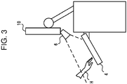
- Fig. 3 is a schematic diagram illustrating the relationship between the sensor 6 and the touch panel 4.
- the sensor 6 is appropriately installed in a position where it can detect the hand H of the operator near the touch panel 4 (the detection range of the sensor 6 is schematically indicated by a broken line).
- the sensor 6 detects the shape and size of the hand at every predetermined sampling rate, and outputs detection information indicating the shape and size detected to the identification circuit 7.
- the identification circuit 7 is a processor that identifies the type of finger having touched the touch panel 4. For example, the identification circuit 7 stores in advance statistical information in which the shape and size of the hand are associated with the finger type. The identification circuit 7 compares the detection information from the sensor 6 with the statistical information, and thereby identifies the type of each finger of the hand detected by the sensor 6. In this manner, the identification circuit 7 can identify the type of each finger located around the touch panel 4. The identification circuit 7 performs this identification process at every predetermined sampling rate.
- the system control circuit 8 is a processor that controls each part of the ultrasound diagnosis apparatus.
- the system control circuit 8 stores a program for controlling each part of the ultrasound diagnosis apparatus and executes it.
- the system control circuit 8 outputs an ultrasound image generated by the image generating circuit 3 to the display control circuit 9.
- the system control circuit 8 performs an operation instruction associated with the finger type identified by the identification circuit 7 based on the association information stored in the memory circuit 5. This operation instruction corresponds to an operation instruction provided by touch typing. Described below is the process performed in response to an operation instruction provided by touch typing.
- the touch panel 4 in the operation state for receiving touch typing need not display soft keys. Having detected a touch of the operator's finger, the touch panel 4 outputs a touched position signal indicating the touched position on the touch panel 4 to the system control circuit 8 and the identification circuit 7.
- the identification circuit 7 compares the touched position signal with the type of the finger near the touch panel 4, and thereby identifies the type of the finger that has touched the touch panel 4.
- the system control circuit 8 compares the type of the finger that has touched the touch panel 4 with the association information stored in the memory circuit 5, and thereby specifies an operation instruction associated with the type of the finger that has touched the touch panel 4.
- the system control circuit 8 uses the association information of selected one of the tables. Then, the system control circuit 8 controls each part of the ultrasound diagnosis apparatus so as to perform the operation instruction specified.
- the display control circuit 9 is a processor that displays ultrasound images and other information on the display 10.
- the display 10 is an example of the display in the claims.
- the display 10 is formed of a display device such as a liquid crystal display (LCD) or an organic electro-luminescence (EL) display.
- the display control circuit 9 displays association information on the display 10.
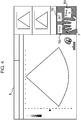
- Fig. 4 is a schematic diagram of association information displayed on the display 10.
- the display control circuit 9 displays association information alongside the ultrasound image.
- a schematic illustration P of the hand and texts TX1, TX2, TX3 each indicating an operation instruction associated with each finger are displayed at the lower right of the display screen D.
- the specific design for displaying the association information is not limited to such an illustration and text information, but may be set appropriately.
- the operation instruction is associated with the finger type, and the operation instruction specified by the type of the finger having touched the touch panel 4 is performed. This facilitates operator's touch typing without looking at the touch panel 4.
- an operation instruction "Freeze" is associated with the middle finger as a finger type
- the operator wishes to perform the Freeze operation during an ultrasound examination he/she can perform the Freeze operation by touching the touch panel 4 with the middle finger.
- the operation instruction of Freeze is entered.
- the operator can perform a simple operation of touching any position on the touch panel 4 with the middle finger without looking at the touch panel 4.
- the operator may touch the touch panel 4 with the finger in association with the operation instruction.
- the operation instructions set in the association information may include a switch instruction for switching on/off of the touch typing operation.
- the switch instruction is associated with the thumb as a finger type
- the operator wishes to perform touch typing he/she can turn on the touch typing operation by touching the touch panel 4 with the thumb.
- the touch typing operation can be switched on no matter where the thumb touches on the touch panel 4.
- the identification circuit 7 identifies the type of another finger that has touched the touch panel 4 with the finger associated with the switch instruction.
- the system control circuit 8 compares the type of the other finger thus identified with the association information, and thereby specifies an operation instruction associated with the type of the other finger. Then, the system control circuit 8 controls each part of the ultrasound diagnosis apparatus so as to perform the operation instruction specified.
- the display control circuit 9 displays soft keys each corresponding to an operation instruction on the touch panel 4. In this state, the touch typing operation is OFF. In this OFF state, the operator performs operation input by touching a soft key corresponding to a desired operation instruction in the same manner as the conventional soft key input.
- the operator can perform operation input on the ultrasound diagnosis apparatus while suitably switching between the touch typing operation and the conventional soft key operation.
- the operator can operate the touch panel while appropriately switching the operation input mode.
- the operability of the touch panel can be improved.
- operation instructions provided by touch typing may include the display and movement of a cursor on the display 10.
- the cursor include various cursors used by common pointing devices, measurement calipers for measuring the dimension of tissue depicted in an ultrasound image, and the like.
- the display control circuit 9 moves the position of the cursor according to the movement of the finger. Thereby, while viewing an ultrasound image displayed on the display 10, the operator can move the cursor by moving the finger touching the touch panel 4 without looking at the touch panel 4.
- an operation instruction may be associated with a combination of the two or more types of fingers.
- the display control circuit 9 moves the cursor according to the movement of these two fingers.
- the identification circuit 7 identifies the types of all fingers that are touching the touch panel 4 at the same time.
- Fig. 5 is a flowchart illustrating the operation of the ultrasound diagnosis apparatus according to the first embodiment.
- the operator performs touch typing while watching an ultrasound image during an ultrasound examination.
- Step S101 When the touch typing operation is ON, the display control circuit 9 sequentially displays ultrasound images with association information in which the finger type and the operation instruction are associated with each other on the display 10.
- Step S102 When the operator puts his/her hand close to the touch panel 4, the sensor 6 detects the shape and size of the hand of the operator. The sensor 6 outputs detection information indicating the shape and size detected to the identification circuit 7.
- Step S103 The identification circuit 7 compares the detection information from the sensor 6 with statistical information in which the shape and size of the hand are associated with the finger type, and thereby identifies the type of each finger of the hand detected by the sensor 6.
- Step S 104 The touch panel 4 outputs a touched position signal indicating the position where the finger touched to the system control circuit 8 and the identification circuit 7.
- the identification circuit 7 identifies the type of the finger that has touched the touch panel 4 by comparing the touched position signal with the type of the finger near the touch panel 4.
- Step S105 The system control circuit 8 compares the type of the finger that has touched the touch panel 4 with the association information stored in the memory circuit 5, and thereby specifies an operation instruction associated with the type of the finger that has touched the touch panel 4. Then, the system control circuit 8 controls each part of the ultrasound diagnosis apparatus so as to perform the operation instruction specified.
- the operator can perform easy and convenient touch typing by touching any position on the touch panel 4 with a finger corresponding to a desired operation instruction without looking at the touch panel 4. Thereby, even when a flat touch panel is used, it is possible to improve the quickness and accuracy of operation input using the touch panel.
- An ultrasound diagnosis apparatus according to a first modification of the first embodiment will be described. In the following, differences from the ultrasound diagnosis apparatus of the first embodiment will be mainly described. The same description as already described in the first embodiment may not be repeated.
- the memory circuit 5 of the first modification stores association information for each partial area of the touch panel 4.
- Fig. 6 is a schematic diagram illustrating the relationship between the partial area and the association information stored in the memory circuit 5 of the first modification.
- a partial area A1 is set at the lower right of the touch panel 4 and the partial area A2 is set at the lower left of the touch panel 4.
- These partial areas (A1, A2) may be preset or may be set by operator's operation.
- association information T2 the finger type (Finger: finger 1 to finger 5) and the operation instruction (Switch CODE: 0 ⁇ 1000, 0 ⁇ 1500, 0 ⁇ 1300, 0 ⁇ 1400, 0 ⁇ 1A00) are associated with each other with respect to each of the partial areas A1 and A2.
- the system control circuit 8 specifies a partial area touched by the finger based on the touched position signal from the touch panel 4.
- the system control circuit 8 compares association information corresponding to the partial area with the type of the finger that has touched the touch panel 4 to thereby specify an operation instruction associated with the type of the finger that has touched the touch panel 4 in the association information. Then, the system control circuit 8 controls each part of the ultrasound diagnosis apparatus so as to perform the operation instruction specified.
- the association information can be set in a partial area of the touch panel where the operator can easily touch according to the positional relationship. Thereby, it is possible to improve the operability for performing operation input according to the positional relationship between the ultrasound diagnosis apparatus and the bed.
- An ultrasound diagnosis apparatus according to a second modification of the first embodiment will be described. In the following, differences from the ultrasound diagnosis apparatus of the first embodiment will be mainly described. The same description as already described in the first embodiment may not be repeated.
- Fig. 7 is a block diagram illustrating a configuration of a second modification.
- the identification circuit 7 of the second modification includes a specifying circuit 71.
- the specifying circuit 71 is a processor that specifies the operator based on a detection result obtained by the sensor. For example, the specifying circuit 71 stores shape and size information indicating the shape and size of the hand with respect to each operator ID. The specifying circuit 71 compares detection information from the sensor 6 with the shape and size information, and thereby specifies the operator. The specifying circuit 71 outputs the operator ID of the operator specified to the system control circuit 8.
- the memory circuit 5 stores association information with respect to each operator ID. For example, the operator can prepare association information according to the habit and preference of his/her operation and store it in the memory circuit 5 in advance.
- the system control circuit 8 performs an operation instruction based on the association information corresponding to the operator ID from the specifying circuit 71. For example, when the operator puts his/her hand close to the touch panel 4, the sensor 6 outputs detection information to the specifying circuit 71.
- the specifying circuit 71 specifies the operator based on the detection information, and outputs the operator ID of the operator specified to the system control circuit 8.
- the system control circuit 8 compares the type of the finger that has touched the touch panel 4 with the association information corresponding to the operator ID, and thereby specifies an operation instruction associated with the type of the finger that has touched the touch panel 4. Then, the system control circuit 8 controls each part of the ultrasound diagnosis apparatus so as to perform the operation instruction specified.
- association information is automatically selected according to the preference of each operator. Thereby, the operability of the touch panel for operation input can be improved according to the preference of each operator.
- Fig. 8 is a block diagram illustrating a configuration of an ultrasound diagnosis apparatus according to a third modification.
- the ultrasound diagnosis apparatus of the third modification identifies the type of the finger without using the sensor 6.
- differences from the ultrasound diagnosis apparatus of the first embodiment will be mainly described. The same description as already described in the first embodiment may not be repeated.
- the touch panel 4 detects a position touched by each of the fingers and outputs touched position information to the system control circuit 8 and the identification circuit 7. Thereby, the identification circuit 7 detects the positions of the fingers that are touching the touch panel 4.
- the identification circuit 7 identifies the type of each of the fingers based on the positional relationship of the fingers detected.
- Fig. 9 is a schematic diagram of a plurality of fingers touching the touch panel 4.
- the identification circuit 7 stores in advance statistical information on the shape of the hand.
- the statistical information includes the ratio of the lengths of the fingers and the like. With this, the relative positional relationship when each finger touches the touch panel 4 can be obtained.
- the identification circuit 7 compares the statistical information with the touched position information on the touch panel 4, and thereby individually identifies the type of each finger that has touched each touched position.
- the touched position is indicated by coordinates (finger X1 to finger X5, finger Y1 to finger Y4) with respect to each finger type identified.
- the operator can once release a finger corresponding to a desired operation instruction from the touch panel 4. At this time, the other fingers are still touching the touch panel 4. Then, the operator can enter a desired operation instruction by touching again the touch panel 4 with the finger corresponding to the desired operation instruction.
- the identification circuit 7 compares touched position information indicating a position touched by the finger that has touched again the touch panel 4 with the coordinates of the fingers identified before the finger has touched again the touch panel 4, and identifies the type of the finger that has touched again the touch panel 4. For example, in the example of Fig. 9 , when the touched position information of the finger that has touched again the touch panel 4 indicates the coordinates of "finger X3, finger Y1", the identification circuit 7 identifies the type of the finger that has touched again as "middle finger”. Incidentally, when a finger touches again the touch panel 4, the coordinates may differ from the previous coordinates. The allowable range of difference used for the identification may be appropriately set. Then, the system control circuit 8 controls each part of the ultrasound diagnosis apparatus so as to perform an operation instruction associated with the type of the finger identified.
- the operator can perform easy and convenient touch typing by touching any position on the touch panel 4 with a finger corresponding to a desired operation instruction without looking at the touch panel 4. Thereby, even when a flat touch panel is used, it is possible to improve the quickness and accuracy of operation input using the touch panel.
- Fig. 10 is a block diagram illustrating a configuration of an ultrasound diagnosis apparatus according to a fourth modification.
- the ultrasound diagnosis apparatus of the fourth modification is configured to be capable of receiving operation instructions without using a touch panel.
- differences from the first embodiment will be mainly described. The same description as already described in the first embodiment may not be repeated.
- a projector 11 projects light indicating a predetermined operation area.
- the projected light may be visible light or non-visible light.
- the light projected by the projector 11 is only required to indicate at least the outer edge of the operation area.
- a general light source, an optical modulator, a lens, and the like may be appropriately used for the hardware configuration of the projector 11.
- the sensor 6 detects the shape and size of the operator's hand in the vicinity of the operation area.
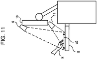
- Fig. 11 is a schematic diagram illustrating the relationship between the projector 11 and the sensor 6 and the operation area A3.
- the projector 11 projects light that indicates the operation area A3 onto a nearby flat plate or a bed.
- the function of the operation area A3 thus indicated corresponds to the function of the operation surface of the touch panel 4 in the above embodiment.
- the sensor 6 is appropriately installed in a position where it can detect the hand H of the operator in the vicinity of the operation area A3.
- the detection range of the sensor 6 is determined so as to detect the hand H located within a predetermined distance from the flat plate B and in the operation area A3. Specific numerical values of the detection range may be determined as appropriate.
- the senor 6 detects the shape and size of the hand H of the operator at each predetermined sampling rate, and outputs detection information indicating the shape and size detected to the identification circuit 7.
- the identification circuit 7 identifies a finger in the vicinity of the operation area A3 as in the above embodiment.
- operation instructions can be provided without using the touch panel 4 by projecting an operation area on a flat plate, a desk, a wall, a bed, or the like around the ultrasound diagnosis apparatus and using the operation area as the operation surface of the touch panel 4.
- the operation area as the operation surface of the touch panel 4.
- processor refers to a circuit such as, for example, a central processing unit (CPU), a graphics processing unit (GPU), an application specific integrated circuit (ASIC), a programmable logic device including a simple programmable logic device (SPLD) and a complex programmable logic device (CPLD), a field programmable gate array (FPGA), or the like.
- the processor reads programs out of a memory circuit and executes them to thereby realize the functions.
- the programs need not necessarily be stored in a memory circuit, but may be directly incorporated in the circuit of the processor. In this case, the processor realizes the functions by reading and executing the programs incorporated in the circuit.
- Each processor of the embodiments need not necessarily be configured as a single circuit.
- a plurality of independent circuits may be combined to form a single processor for implementing the functions.
- a plurality of constituent elements in Fig. 1 may be integrated into one processor to realize the functions.
- the ultrasound diagnosis apparatus of at least one embodiment described above it is possible to improve the operability of the touch panel for operation input.
Abstract
Description
- Embodiments described herein relate generally to an ultrasound diagnosis apparatus.
- Some conventional ultrasound diagnosis apparatuses receive operation instructions from an operator via physical operation switches such as button switches and dials and a touch command screen (TCS). The touch command screen includes a touch panel, and is an operation device that displays soft keys on the touch panel and receives an operation instruction corresponding to a soft key at a position where an operator's finger or the like has touched. Hereinafter, the touch command screen and the touch panel may sometimes be equated for the sake of explanation.
- There are also known ultrasound diagnosis apparatuses that receive operation instructions via a touch command screen without the aforementioned physical operation switches. Such an ultrasound diagnosis apparatus displays soft keys each corresponding to a function that has been implemented by an operation instruction provided via a physical operation switch on the touch panel. The layout of the soft keys displayed on the touch panel can be dynamically changed according to various operation modes of the ultrasound diagnosis apparatus and operation instructions from the operator.
- However, when the operator provides an operation instruction via the touch panel, inconvenience may occur in the operation. As one example may be cited the case where the operator performs touch typing. When using physical operation switches, the operator can perform touch typing while feeling the unevenness of the operation switches by the sense of touch in his/her fingers. On the other hand, when using a flat touch panel, it is difficult to perform touch typing while figuring out the position of each soft key, and the operator may make a mistake in providing an operation instruction. For example, when the ultrasound diagnosis apparatus is used in mass screening, operation instructions are provided according to a roughly determined routine, and quickness and accuracy are required in performing as many examinations as possible in a short period of time. The operation input method using the touch panel sometimes makes the operator feel inconvenient in such cases.
-
-
Fig. 1 is a block diagram illustrating a configuration of an ultrasound diagnosis apparatus according to a first embodiment; -
Fig. 2 is a schematic diagram of association information according to the first embodiment; -
Fig. 3 is a schematic diagram illustrating a relationship between a sensor and a touch panel according to the first embodiment; -
Fig. 4 is a schematic diagram of the association information displayed on a display according to the first embodiment; -
Fig. 5 is a flowchart illustrating the operation of the ultrasound diagnosis apparatus according to the first embodiment; -
Fig. 6 is a schematic diagram illustrating a relationship between association information and partial areas according to a first modification; -
Fig. 7 is a block diagram illustrating a configuration of a second modification; -
Fig. 8 is a block diagram illustrating a configuration of an ultrasound diagnosis apparatus according to a third modification; -
Fig. 9 is a schematic diagram of a plurality of fingers touching on a touch panel according to the third modification; -
Fig. 10 is a block diagram illustrating a configuration of an ultrasound diagnosis apparatus according to a fourth modification; and -
Fig. 11 is a schematic diagram illustrating a relationship between a projector and a sensor and an operation area according to the fourth modification. - In general, according to one embodiment, an ultrasound diagnosis apparatus is capable of receiving an operation instruction via a touch panel. The ultrasound diagnosis apparatus includes a storage, an identification unit, and a controller. The storage stores association information in which operation instructions are each associated with a finger type. The identification unit identifies the finger type of a finger that has touched any position on the touch panel. The controller performs one of the operation instructions associated with the finger type identified based on the association information.
- Referring now to the drawings, a description is given of an ultrasound diagnosis apparatus according to embodiments.
-
Fig. 1 is a block diagram illustrating a configuration of an ultrasound diagnosis apparatus according to a first embodiment. The ultrasound diagnosis apparatus of the first embodiment includes anultrasound probe 1, a transmitting/receiving circuit 2, animage generating circuit 3, atouch panel 4, amemory circuit 5, asensor 6, anidentification circuit 7, a system control circuit 8, adisplay control circuit 9, and adisplay 10. - The
ultrasound probe 1 transmits ultrasound waves to a subject and receives reflected waves therefrom. Theultrasound probe 1 outputs an echo signal based on the reflected waves from the subject to the transmitting/receivingcircuit 2. - The transmitting/receiving
circuit 2 supplies an electric signal to theultrasound probe 1 according to a control signal from the system control circuit 8 to cause it to transmit ultrasound waves that have been beamformed to a predetermined focal point (i.e., subjected to transmission beamforming). Further, the transmitting/receivingcircuit 2 receives the echo signal from theultrasound probe 1. The transmitting/receivingcircuit 2 performs a delay process on the echo signal, thereby converting the analog echo signal into a received signal with phased addition. The transmitting/receivingcircuit 2 outputs the received signal to theimage generating circuit 3. - The image generating
circuit 3 generates an ultrasound image based on the received signal from the transmitting/receivingcircuit 2. For example, theimage generating circuit 3 performs band-pass filtering on the received signal. Thereafter, theimage generating circuit 3 detects the envelope of the output signal, and performs a compression process on the detected data by logarithmic conversion. The image generatingcircuit 3 converts the received signal subjected to the compression process (ultrasound raster data) into a coordinate system for display (scan conversion), thereby generating an ultrasound image. The ultrasound image is displayed on thedisplay 10 by the system control circuit 8 and thedisplay control circuit 9. - The
touch panel 4 receives an operation by an operator such as a doctor or a technician, and outputs an operation instruction corresponding to the content of the operation to the system control circuit 8. For example, in a general operation state, thetouch panel 4 displays soft keys and detects a touch of the operator's finger or the like. Thetouch panel 4 outputs an operation instruction corresponding to a soft key displayed at the touched position detected to the system control circuit 8. In another operation state, thetouch panel 4 receives an operation instruction by touch typing (details will be described later). - The
memory circuit 5 is an example of the storage in the claims. Thememory circuit 5 stores association information in which the type of a finger is associated with an operation instruction.Fig. 2 schematically illustrates the association information. For example, the association information T1 is table information. In the association information T1, the finger type (Finger:finger 1 to finger 5) and the operation instruction (Switch CODE: 0×1000, 0×1500, 0×1300, 0×1400, 0×1A00) are associated with each other. Specific types (thumb, index finger, ..., little finger) assigned to the finger type (each Finger) can be set and changed as appropriate by the operator or the like. In addition, specific operation instructions (Freeze, SET, NEXT, etc.) assigned to the operation instruction (each Switch CODE) can be set and changed as appropriate by the operator or the like. - Incidentally, the
memory circuit 5 may store the association information in a plurality of tables. In this case, for example, the operator selects a desired one of the tables, and the association information of the selected table is used. Thereby, the operator can select a desired table from a plurality of tables having different associations between the finger type and the operation instruction. - The
sensor 6 detects the shape and size of the operator's hand. Example of the hardware used for thesensor 6 include an optical sensor, a camera, and the like.Fig. 3 is a schematic diagram illustrating the relationship between thesensor 6 and thetouch panel 4. Thesensor 6 is appropriately installed in a position where it can detect the hand H of the operator near the touch panel 4 (the detection range of thesensor 6 is schematically indicated by a broken line). For example, thesensor 6 detects the shape and size of the hand at every predetermined sampling rate, and outputs detection information indicating the shape and size detected to theidentification circuit 7. - The
identification circuit 7 is a processor that identifies the type of finger having touched thetouch panel 4. For example, theidentification circuit 7 stores in advance statistical information in which the shape and size of the hand are associated with the finger type. Theidentification circuit 7 compares the detection information from thesensor 6 with the statistical information, and thereby identifies the type of each finger of the hand detected by thesensor 6. In this manner, theidentification circuit 7 can identify the type of each finger located around thetouch panel 4. Theidentification circuit 7 performs this identification process at every predetermined sampling rate. - The system control circuit 8 is a processor that controls each part of the ultrasound diagnosis apparatus. For example, the system control circuit 8 stores a program for controlling each part of the ultrasound diagnosis apparatus and executes it. For example, the system control circuit 8 outputs an ultrasound image generated by the
image generating circuit 3 to thedisplay control circuit 9. The system control circuit 8 performs an operation instruction associated with the finger type identified by theidentification circuit 7 based on the association information stored in thememory circuit 5. This operation instruction corresponds to an operation instruction provided by touch typing. Described below is the process performed in response to an operation instruction provided by touch typing. - The
touch panel 4 in the operation state for receiving touch typing need not display soft keys. Having detected a touch of the operator's finger, thetouch panel 4 outputs a touched position signal indicating the touched position on thetouch panel 4 to the system control circuit 8 and theidentification circuit 7. Theidentification circuit 7 compares the touched position signal with the type of the finger near thetouch panel 4, and thereby identifies the type of the finger that has touched thetouch panel 4. The system control circuit 8 compares the type of the finger that has touched thetouch panel 4 with the association information stored in thememory circuit 5, and thereby specifies an operation instruction associated with the type of the finger that has touched thetouch panel 4. When thememory circuit 5 stores the association information in a plurality of tables, the system control circuit 8 uses the association information of selected one of the tables. Then, the system control circuit 8 controls each part of the ultrasound diagnosis apparatus so as to perform the operation instruction specified. - The
display control circuit 9 is a processor that displays ultrasound images and other information on thedisplay 10. Thedisplay 10 is an example of the display in the claims. Thedisplay 10 is formed of a display device such as a liquid crystal display (LCD) or an organic electro-luminescence (EL) display. For example, thedisplay control circuit 9 displays association information on thedisplay 10. -
Fig. 4 is a schematic diagram of association information displayed on thedisplay 10. For example, thedisplay control circuit 9 displays association information alongside the ultrasound image. In the example ofFig. 4 , a schematic illustration P of the hand and texts (TX1, TX2, TX3) each indicating an operation instruction associated with each finger are displayed at the lower right of the display screen D. The specific design for displaying the association information is not limited to such an illustration and text information, but may be set appropriately. - As described above, the operation instruction is associated with the finger type, and the operation instruction specified by the type of the finger having touched the
touch panel 4 is performed. This facilitates operator's touch typing without looking at thetouch panel 4. For example, in the case where an operation instruction "Freeze" is associated with the middle finger as a finger type, when the operator wishes to perform the Freeze operation during an ultrasound examination, he/she can perform the Freeze operation by touching thetouch panel 4 with the middle finger. At this time, regardless of the position where the middle finger touches on thetouch panel 4, the operation instruction of Freeze is entered. Thus, while viewing an ultrasound image displayed on thedisplay 10, the operator can perform a simple operation of touching any position on thetouch panel 4 with the middle finger without looking at thetouch panel 4. When the operator wishes to enter another operation instruction, the operator may touch thetouch panel 4 with the finger in association with the operation instruction. - The operation instructions set in the association information may include a switch instruction for switching on/off of the touch typing operation. For example, in the case where the switch instruction is associated with the thumb as a finger type, when the operator wishes to perform touch typing, he/she can turn on the touch typing operation by touching the
touch panel 4 with the thumb. At this time, the touch typing operation can be switched on no matter where the thumb touches on thetouch panel 4. Then, while touching thetouch panel 4 with the thumb, the operator touches thetouch panel 4 with another finger to enter an operation instruction. - While the finger associated with the switch instruction (the thumb in this example) is touching the
touch panel 4, theidentification circuit 7 identifies the type of another finger that has touched thetouch panel 4 with the finger associated with the switch instruction. The system control circuit 8 compares the type of the other finger thus identified with the association information, and thereby specifies an operation instruction associated with the type of the other finger. Then, the system control circuit 8 controls each part of the ultrasound diagnosis apparatus so as to perform the operation instruction specified. - When the finger associated with the switch instruction (the thumb in this example) is not touching the
touch panel 4, that is, when theidentification circuit 7 does not identify the thumb, thedisplay control circuit 9 displays soft keys each corresponding to an operation instruction on thetouch panel 4. In this state, the touch typing operation is OFF. In this OFF state, the operator performs operation input by touching a soft key corresponding to a desired operation instruction in the same manner as the conventional soft key input. - As described above, with the configuration that the operator can operate while switching on/off the touch typing operation, the operator can perform operation input on the ultrasound diagnosis apparatus while suitably switching between the touch typing operation and the conventional soft key operation. Thereby, the operator can operate the touch panel while appropriately switching the operation input mode. Thus, the operability of the touch panel can be improved.
- Besides, operation instructions provided by touch typing may include the display and movement of a cursor on the
display 10. Examples of the cursor include various cursors used by common pointing devices, measurement calipers for measuring the dimension of tissue depicted in an ultrasound image, and the like. For example, as a result of finger type identification by theidentification circuit 7, when the finger is the one associated with the movement operation, thedisplay control circuit 9 moves the position of the cursor according to the movement of the finger. Thereby, while viewing an ultrasound image displayed on thedisplay 10, the operator can move the cursor by moving the finger touching thetouch panel 4 without looking at thetouch panel 4. - Further, an operation instruction may be associated with a combination of the two or more types of fingers. For example, when the above-described cursor movement operation is associated with the index finger and the middle finger and both the index finger and the middle finger touch the
touch panel 4, thedisplay control circuit 9 moves the cursor according to the movement of these two fingers. In this case, theidentification circuit 7 identifies the types of all fingers that are touching thetouch panel 4 at the same time. -
Fig. 5 is a flowchart illustrating the operation of the ultrasound diagnosis apparatus according to the first embodiment. In the following, an example will be described in which the operator performs touch typing while watching an ultrasound image during an ultrasound examination. - Step S101: When the touch typing operation is ON, the
display control circuit 9 sequentially displays ultrasound images with association information in which the finger type and the operation instruction are associated with each other on thedisplay 10. - Step S102: When the operator puts his/her hand close to the
touch panel 4, thesensor 6 detects the shape and size of the hand of the operator. Thesensor 6 outputs detection information indicating the shape and size detected to theidentification circuit 7. - Step S103: The
identification circuit 7 compares the detection information from thesensor 6 with statistical information in which the shape and size of the hand are associated with the finger type, and thereby identifies the type of each finger of the hand detected by thesensor 6. - Step S 104: The
touch panel 4 outputs a touched position signal indicating the position where the finger touched to the system control circuit 8 and theidentification circuit 7. Theidentification circuit 7 identifies the type of the finger that has touched thetouch panel 4 by comparing the touched position signal with the type of the finger near thetouch panel 4. - Step S105: The system control circuit 8 compares the type of the finger that has touched the
touch panel 4 with the association information stored in thememory circuit 5, and thereby specifies an operation instruction associated with the type of the finger that has touched thetouch panel 4. Then, the system control circuit 8 controls each part of the ultrasound diagnosis apparatus so as to perform the operation instruction specified. - With the ultrasound diagnosis apparatus according to the first embodiment, the operator can perform easy and convenient touch typing by touching any position on the
touch panel 4 with a finger corresponding to a desired operation instruction without looking at thetouch panel 4. Thereby, even when a flat touch panel is used, it is possible to improve the quickness and accuracy of operation input using the touch panel. - An ultrasound diagnosis apparatus according to a first modification of the first embodiment will be described. In the following, differences from the ultrasound diagnosis apparatus of the first embodiment will be mainly described. The same description as already described in the first embodiment may not be repeated.
- The
memory circuit 5 of the first modification stores association information for each partial area of thetouch panel 4.Fig. 6 is a schematic diagram illustrating the relationship between the partial area and the association information stored in thememory circuit 5 of the first modification. In the following, an example will be described in which a partial area A1 is set at the lower right of thetouch panel 4 and the partial area A2 is set at the lower left of thetouch panel 4. These partial areas (A1, A2) may be preset or may be set by operator's operation. In association information T2, the finger type (Finger:finger 1 to finger 5) and the operation instruction (Switch CODE: 0×1000, 0×1500, 0×1300, 0×1400, 0×1A00) are associated with each other with respect to each of the partial areas A1 and A2. - At the time of the touch typing operation, the system control circuit 8 specifies a partial area touched by the finger based on the touched position signal from the
touch panel 4. The system control circuit 8 compares association information corresponding to the partial area with the type of the finger that has touched thetouch panel 4 to thereby specify an operation instruction associated with the type of the finger that has touched thetouch panel 4 in the association information. Then, the system control circuit 8 controls each part of the ultrasound diagnosis apparatus so as to perform the operation instruction specified. - Normally, when diagnosing with an ultrasound diagnosis apparatus, the operator holds an ultrasound probe on the right hand and performs operation input on the touch panel with the left hand. However, depending on the positional relationship between the ultrasound diagnosis apparatus and the bed, there are cases where the operator holds an ultrasound probe on the left hand and performs operation input on the touch panel with the right hand. With the ultrasound diagnosis apparatus of the first modification, the association information can be set in a partial area of the touch panel where the operator can easily touch according to the positional relationship. Thereby, it is possible to improve the operability for performing operation input according to the positional relationship between the ultrasound diagnosis apparatus and the bed.
- An ultrasound diagnosis apparatus according to a second modification of the first embodiment will be described. In the following, differences from the ultrasound diagnosis apparatus of the first embodiment will be mainly described. The same description as already described in the first embodiment may not be repeated.
-
Fig. 7 is a block diagram illustrating a configuration of a second modification. Theidentification circuit 7 of the second modification includes a specifyingcircuit 71. The specifyingcircuit 71 is a processor that specifies the operator based on a detection result obtained by the sensor. For example, the specifyingcircuit 71 stores shape and size information indicating the shape and size of the hand with respect to each operator ID. The specifyingcircuit 71 compares detection information from thesensor 6 with the shape and size information, and thereby specifies the operator. The specifyingcircuit 71 outputs the operator ID of the operator specified to the system control circuit 8. - The
memory circuit 5 stores association information with respect to each operator ID. For example, the operator can prepare association information according to the habit and preference of his/her operation and store it in thememory circuit 5 in advance. The system control circuit 8 performs an operation instruction based on the association information corresponding to the operator ID from the specifyingcircuit 71. For example, when the operator puts his/her hand close to thetouch panel 4, thesensor 6 outputs detection information to the specifyingcircuit 71. The specifyingcircuit 71 specifies the operator based on the detection information, and outputs the operator ID of the operator specified to the system control circuit 8. The system control circuit 8 compares the type of the finger that has touched thetouch panel 4 with the association information corresponding to the operator ID, and thereby specifies an operation instruction associated with the type of the finger that has touched thetouch panel 4. Then, the system control circuit 8 controls each part of the ultrasound diagnosis apparatus so as to perform the operation instruction specified. - With the ultrasound diagnosis apparatus of the second modification, association information is automatically selected according to the preference of each operator. Thereby, the operability of the touch panel for operation input can be improved according to the preference of each operator.
-
Fig. 8 is a block diagram illustrating a configuration of an ultrasound diagnosis apparatus according to a third modification. Differently from the first embodiment, the ultrasound diagnosis apparatus of the third modification identifies the type of the finger without using thesensor 6. In the following, differences from the ultrasound diagnosis apparatus of the first embodiment will be mainly described. The same description as already described in the first embodiment may not be repeated. - When the operator touches the
touch panel 4 with a plurality of fingers, thetouch panel 4 detects a position touched by each of the fingers and outputs touched position information to the system control circuit 8 and theidentification circuit 7. Thereby, theidentification circuit 7 detects the positions of the fingers that are touching thetouch panel 4. - The
identification circuit 7 identifies the type of each of the fingers based on the positional relationship of the fingers detected.Fig. 9 is a schematic diagram of a plurality of fingers touching thetouch panel 4. Theidentification circuit 7 stores in advance statistical information on the shape of the hand. The statistical information includes the ratio of the lengths of the fingers and the like. With this, the relative positional relationship when each finger touches thetouch panel 4 can be obtained. Theidentification circuit 7 compares the statistical information with the touched position information on thetouch panel 4, and thereby individually identifies the type of each finger that has touched each touched position. InFig. 9 , the touched position is indicated by coordinates (finger X1 to finger X5, finger Y1 to finger Y4) with respect to each finger type identified. - Among the fingers touching the
touch panel 4, the operator can once release a finger corresponding to a desired operation instruction from thetouch panel 4. At this time, the other fingers are still touching thetouch panel 4. Then, the operator can enter a desired operation instruction by touching again thetouch panel 4 with the finger corresponding to the desired operation instruction. - At this time, the
identification circuit 7 compares touched position information indicating a position touched by the finger that has touched again thetouch panel 4 with the coordinates of the fingers identified before the finger has touched again thetouch panel 4, and identifies the type of the finger that has touched again thetouch panel 4. For example, in the example ofFig. 9 , when the touched position information of the finger that has touched again thetouch panel 4 indicates the coordinates of "finger X3, finger Y1", theidentification circuit 7 identifies the type of the finger that has touched again as "middle finger". Incidentally, when a finger touches again thetouch panel 4, the coordinates may differ from the previous coordinates. The allowable range of difference used for the identification may be appropriately set. Then, the system control circuit 8 controls each part of the ultrasound diagnosis apparatus so as to perform an operation instruction associated with the type of the finger identified. - Also with the ultrasound diagnosis apparatus of the third modification, the operator can perform easy and convenient touch typing by touching any position on the
touch panel 4 with a finger corresponding to a desired operation instruction without looking at thetouch panel 4. Thereby, even when a flat touch panel is used, it is possible to improve the quickness and accuracy of operation input using the touch panel. -
Fig. 10 is a block diagram illustrating a configuration of an ultrasound diagnosis apparatus according to a fourth modification. Differently from the first embodiment, the ultrasound diagnosis apparatus of the fourth modification is configured to be capable of receiving operation instructions without using a touch panel. In the following, differences from the first embodiment will be mainly described. The same description as already described in the first embodiment may not be repeated. - A
projector 11 projects light indicating a predetermined operation area. The projected light may be visible light or non-visible light. The light projected by theprojector 11 is only required to indicate at least the outer edge of the operation area. A general light source, an optical modulator, a lens, and the like may be appropriately used for the hardware configuration of theprojector 11. - The
sensor 6 detects the shape and size of the operator's hand in the vicinity of the operation area.Fig. 11 is a schematic diagram illustrating the relationship between theprojector 11 and thesensor 6 and the operation area A3. Theprojector 11 projects light that indicates the operation area A3 onto a nearby flat plate or a bed. The function of the operation area A3 thus indicated corresponds to the function of the operation surface of thetouch panel 4 in the above embodiment. Thesensor 6 is appropriately installed in a position where it can detect the hand H of the operator in the vicinity of the operation area A3. For example, the detection range of thesensor 6 is determined so as to detect the hand H located within a predetermined distance from the flat plate B and in the operation area A3. Specific numerical values of the detection range may be determined as appropriate. For example, thesensor 6 detects the shape and size of the hand H of the operator at each predetermined sampling rate, and outputs detection information indicating the shape and size detected to theidentification circuit 7. Theidentification circuit 7 identifies a finger in the vicinity of the operation area A3 as in the above embodiment. - With the ultrasound diagnosis apparatus according to the fourth modification, operation instructions can be provided without using the
touch panel 4 by projecting an operation area on a flat plate, a desk, a wall, a bed, or the like around the ultrasound diagnosis apparatus and using the operation area as the operation surface of thetouch panel 4. Thus, it is possible to perform touch typing input using the flat operation area, and the quickness and accuracy of operation input can be improved. - The term "processor" as used herein refers to a circuit such as, for example, a central processing unit (CPU), a graphics processing unit (GPU), an application specific integrated circuit (ASIC), a programmable logic device including a simple programmable logic device (SPLD) and a complex programmable logic device (CPLD), a field programmable gate array (FPGA), or the like. The processor reads programs out of a memory circuit and executes them to thereby realize the functions. The programs need not necessarily be stored in a memory circuit, but may be directly incorporated in the circuit of the processor. In this case, the processor realizes the functions by reading and executing the programs incorporated in the circuit. Each processor of the embodiments need not necessarily be configured as a single circuit. A plurality of independent circuits may be combined to form a single processor for implementing the functions. Besides, a plurality of constituent elements in
Fig. 1 may be integrated into one processor to realize the functions. - According to the ultrasound diagnosis apparatus of at least one embodiment described above, it is possible to improve the operability of the touch panel for operation input.
- While certain embodiments have been described, these embodiments have been presented by way of example only, and are not intended to limit the scope of the inventions. Indeed, the novel embodiments described herein may be embodied in a variety of other forms; furthermore, various omissions, substitutions and changes in the form of the embodiments described herein may be made without departing from the spirit of the inventions. The accompanying claims and their equivalents are intended to cover such forms or modifications as would fall within the scope and spirit of the inventions.
Claims (10)
- An ultrasound diagnosis apparatus capable of receiving an operation instruction via a touch panel, the apparatus comprising:a storage configured to store association information in which operation instructions are each associated with a finger type; andprocessing circuitry configured toidentify finger type of a finger that has touched any position on the touch panel, andperform one of the operation instructions associated with the finger type identified based on the association information.
- The ultrasound diagnosis apparatus of claim 1, wherein
the operation instructions include a switch instruction for turning on and off touch typing operation, and
the processing circuitry is further configured to perform one of the operation instructions associated with the finger type identified based on the association information when the touch typing operation is turned on. - The ultrasound diagnosis apparatus of claim 1, wherein
in the association information, a switch instruction for switching control state of the processing circuitry is associated with a predetermined finger type as one of the operation instruction, and
the processing circuitry is further configured toidentify finger types of a plurality of fingers that have touched the touch panel, andwhen the finger types identified include the predetermined finger type, perform an operation instruction associated with another of the finger types identified. - The ultrasound diagnosis apparatus of claim 3, wherein the processing circuitry is further configured to display soft keys according to the operation instructions on the touch panel when the finger types identified do not include the predetermined finger type.
- The ultrasound diagnosis apparatus of claim 1, wherein
the processing circuitry is further configured to display a cursor on a display,
the operation instructions include a move instruction to move the cursor, and
when the finger type identified is associated with the move instruction, the processing circuitry move display position of the cursor according to movement of the finger. - The ultrasound diagnosis apparatus of claim 1, wherein the processing circuitry is further configured to
detect positions of a plurality of fingers that are touching the touch panel,
identify finger type of each of the fingers based on positional relationship of the fingers, and
compare position of a finger that has touched the touch panel again with the positional relationship to identify finger type of the finger. - The ultrasound diagnosis apparatus of claim 1, wherein the processing circuitry is further configured to display the association information on a display.
- The ultrasound diagnosis apparatus of claim 1, wherein
the storage is further configured to store the association information with respect to each partial area of the touch panel, and
the processing circuitry is further configured to identify finger type of a finger that has touched the partial area. - The ultrasound diagnosis apparatus of claim 1, further comprising a sensor configured to detect shape and size of a hand of an operator, wherein
the processing circuitry is further configured to specify the operator based on a detection result obtained by the sensor,
the storage is further configured to store the association information with respect to each operator ID, and
the processing circuitry is further configured to perform the operation instructions based on the association information corresponding to the operator ID of the operator specified. - An ultrasound diagnosis apparatus capable of receiving an operation instruction via a predetermined operation area, the apparatus comprising:a storage configured to store association information in which operation instructions are each associated with a finger type; andprocessing circuitry configured toidentify finger type of a finger that has entered an operation instruction via any position in the operation area, andperform one of the operation instructions associated with the finger type identified based on the association information.
Applications Claiming Priority (2)
| Application Number | Priority Date | Filing Date | Title |
|---|---|---|---|
| JP2017010847 | 2017-01-25 | ||
| JP2017247135A JP7175605B2 (en) | 2017-01-25 | 2017-12-25 | ultrasound diagnostic equipment |
Publications (2)
| Publication Number | Publication Date |
|---|---|
| EP3355178A1 true EP3355178A1 (en) | 2018-08-01 |
| EP3355178B1 EP3355178B1 (en) | 2023-05-24 |
Family
ID=61024692
Family Applications (1)
| Application Number | Title | Priority Date | Filing Date |
|---|---|---|---|
| EP18153290.4A Active EP3355178B1 (en) | 2017-01-25 | 2018-01-24 | Ultrasound diagnosis apparatus |
Country Status (2)
| Country | Link |
|---|---|
| US (1) | US20180206822A1 (en) |
| EP (1) | EP3355178B1 (en) |
Citations (5)
| Publication number | Priority date | Publication date | Assignee | Title |
|---|---|---|---|---|
| EP0949578A2 (en) * | 1998-04-08 | 1999-10-13 | Nec Corporation | Input device and method utilizing fingerprints of a user |
| US20040085300A1 (en) * | 2001-05-02 | 2004-05-06 | Alec Matusis | Device and method for selecting functions based on intrinsic finger features |
| WO2013148730A2 (en) * | 2012-03-26 | 2013-10-03 | Teratech Corporation | Tablet ultrasound system |
| US20140160035A1 (en) * | 2012-12-10 | 2014-06-12 | Dietmar Michael Sauer | Finger-specific input on touchscreen devices |
| EP3114999A1 (en) * | 2015-07-07 | 2017-01-11 | Samsung Medison Co., Ltd. | Apparatus and method of processing medical image |
Family Cites Families (2)
| Publication number | Priority date | Publication date | Assignee | Title |
|---|---|---|---|---|
| JP4702959B2 (en) * | 2005-03-28 | 2011-06-15 | パナソニック株式会社 | User interface system |
| EP2825938A1 (en) * | 2012-03-15 | 2015-01-21 | Ibrahim Farid Cherradi El Fadili | Extending the free fingers typing technology and introducing the finger taps language technology |
-
2018
- 2018-01-24 EP EP18153290.4A patent/EP3355178B1/en active Active
- 2018-01-25 US US15/879,946 patent/US20180206822A1/en not_active Abandoned
Patent Citations (5)
| Publication number | Priority date | Publication date | Assignee | Title |
|---|---|---|---|---|
| EP0949578A2 (en) * | 1998-04-08 | 1999-10-13 | Nec Corporation | Input device and method utilizing fingerprints of a user |
| US20040085300A1 (en) * | 2001-05-02 | 2004-05-06 | Alec Matusis | Device and method for selecting functions based on intrinsic finger features |
| WO2013148730A2 (en) * | 2012-03-26 | 2013-10-03 | Teratech Corporation | Tablet ultrasound system |
| US20140160035A1 (en) * | 2012-12-10 | 2014-06-12 | Dietmar Michael Sauer | Finger-specific input on touchscreen devices |
| EP3114999A1 (en) * | 2015-07-07 | 2017-01-11 | Samsung Medison Co., Ltd. | Apparatus and method of processing medical image |
Also Published As
| Publication number | Publication date |
|---|---|
| US20180206822A1 (en) | 2018-07-26 |
| EP3355178B1 (en) | 2023-05-24 |
Similar Documents
| Publication | Publication Date | Title |
|---|---|---|
| KR101313218B1 (en) | Handheld ultrasound system | |
| US11428808B2 (en) | Ultrasonic detection method, ultrasonic detection system, and related apparatus | |
| CN103505240A (en) | Ultrasonic imaging device and device and method for automatically adjusting user interface layout | |
| US20170091404A1 (en) | Graphical virtual controls of an ultrasound imaging system | |
| KR20140120540A (en) | Portable ultrasound apparatus, portable ultrasound system and method for diagnosis using ultrasound | |
| US20110242031A1 (en) | Display device with touch function and 2d sensing method thereof | |
| US10042464B2 (en) | Display apparatus including touchscreen device for detecting proximity touch and method for controlling the same | |
| JP2007044519A (en) | Control panel for ultrasonic diagnosis apparatus | |
| CN111297394A (en) | Ultrasonic imaging apparatus, control method thereof, and recording medium | |
| EP3355178A1 (en) | Ultrasound diagnosis apparatus | |
| US11801038B2 (en) | Ultrasound imaging system touch panel with multiple different clusters of controls | |
| JP2010142399A (en) | Ultrasonic diagnostic apparatus | |
| JP7175605B2 (en) | ultrasound diagnostic equipment | |
| JPH0511913A (en) | Keyboard for display device | |
| US20180103926A1 (en) | Ultrasound diagnosis apparatus and medical image processing method | |
| CN111904462B (en) | Method and system for presenting functional data | |
| US10146908B2 (en) | Method and system for enhanced visualization and navigation of three dimensional and four dimensional medical images | |
| JP2010279453A (en) | Medical electronic device and control method of medical electronic device | |
| JP2011072532A (en) | Medical diagnostic imaging apparatus and ultrasonograph | |
| JP2017074213A (en) | Ultrasonic diagnostic apparatus | |
| CN109069104B (en) | Ultrasonic medical detection equipment, imaging control method, imaging system and controller | |
| KR101005797B1 (en) | Control panel of ultrasonic diagnostic apparatus | |
| CN219921084U (en) | Ultrasonic imaging apparatus | |
| KR20140100213A (en) | A probe table, a ultrasound imaging apparatus and method for controlling the ultrasound imaging apparatus | |
| KR20170075999A (en) | Device, method, and ultrasound system for providing personalized user interface |
Legal Events
| Date | Code | Title | Description |
|---|---|---|---|
| PUAI | Public reference made under article 153(3) epc to a published international application that has entered the european phase |
Free format text: ORIGINAL CODE: 0009012 |
|
| STAA | Information on the status of an ep patent application or granted ep patent |
Free format text: STATUS: REQUEST FOR EXAMINATION WAS MADE |
|
| 17P | Request for examination filed |
Effective date: 20180124 |
|
| AK | Designated contracting states |
Kind code of ref document: A1 Designated state(s): AL AT BE BG CH CY CZ DE DK EE ES FI FR GB GR HR HU IE IS IT LI LT LU LV MC MK MT NL NO PL PT RO RS SE SI SK SM TR |
|
| AX | Request for extension of the european patent |
Extension state: BA ME |
|
| STAA | Information on the status of an ep patent application or granted ep patent |
Free format text: STATUS: EXAMINATION IS IN PROGRESS |
|
| 17Q | First examination report despatched |
Effective date: 20190219 |
|
| STAA | Information on the status of an ep patent application or granted ep patent |
Free format text: STATUS: EXAMINATION IS IN PROGRESS |
|
| STAA | Information on the status of an ep patent application or granted ep patent |
Free format text: STATUS: EXAMINATION IS IN PROGRESS |
|
| GRAP | Despatch of communication of intention to grant a patent |
Free format text: ORIGINAL CODE: EPIDOSNIGR1 |
|
| STAA | Information on the status of an ep patent application or granted ep patent |
Free format text: STATUS: GRANT OF PATENT IS INTENDED |
|
| INTG | Intention to grant announced |
Effective date: 20221202 |
|
| GRAS | Grant fee paid |
Free format text: ORIGINAL CODE: EPIDOSNIGR3 |
|
| GRAA | (expected) grant |
Free format text: ORIGINAL CODE: 0009210 |
|
| STAA | Information on the status of an ep patent application or granted ep patent |
Free format text: STATUS: THE PATENT HAS BEEN GRANTED |
|
| AK | Designated contracting states |
Kind code of ref document: B1 Designated state(s): AL AT BE BG CH CY CZ DE DK EE ES FI FR GB GR HR HU IE IS IT LI LT LU LV MC MK MT NL NO PL PT RO RS SE SI SK SM TR |
|
| REG | Reference to a national code |
Ref country code: GB Ref legal event code: FG4D |
|
| REG | Reference to a national code |
Ref country code: CH Ref legal event code: EP |
|
| REG | Reference to a national code |
Ref country code: DE Ref legal event code: R096 Ref document number: 602018050086 Country of ref document: DE |
|
| REG | Reference to a national code |
Ref country code: AT Ref legal event code: REF Ref document number: 1569939 Country of ref document: AT Kind code of ref document: T Effective date: 20230615 |
|
| REG | Reference to a national code |
Ref country code: IE Ref legal event code: FG4D |
|
| P01 | Opt-out of the competence of the unified patent court (upc) registered |
Effective date: 20230607 |
|
| REG | Reference to a national code |
Ref country code: LT Ref legal event code: MG9D |
|
| REG | Reference to a national code |
Ref country code: NL Ref legal event code: MP Effective date: 20230524 |
|
| REG | Reference to a national code |
Ref country code: AT Ref legal event code: MK05 Ref document number: 1569939 Country of ref document: AT Kind code of ref document: T Effective date: 20230524 |
|
| PG25 | Lapsed in a contracting state [announced via postgrant information from national office to epo] |
Ref country code: SE Free format text: LAPSE BECAUSE OF FAILURE TO SUBMIT A TRANSLATION OF THE DESCRIPTION OR TO PAY THE FEE WITHIN THE PRESCRIBED TIME-LIMIT Effective date: 20230524 Ref country code: PT Free format text: LAPSE BECAUSE OF FAILURE TO SUBMIT A TRANSLATION OF THE DESCRIPTION OR TO PAY THE FEE WITHIN THE PRESCRIBED TIME-LIMIT Effective date: 20230925 Ref country code: NO Free format text: LAPSE BECAUSE OF FAILURE TO SUBMIT A TRANSLATION OF THE DESCRIPTION OR TO PAY THE FEE WITHIN THE PRESCRIBED TIME-LIMIT Effective date: 20230824 Ref country code: NL Free format text: LAPSE BECAUSE OF FAILURE TO SUBMIT A TRANSLATION OF THE DESCRIPTION OR TO PAY THE FEE WITHIN THE PRESCRIBED TIME-LIMIT Effective date: 20230524 Ref country code: ES Free format text: LAPSE BECAUSE OF FAILURE TO SUBMIT A TRANSLATION OF THE DESCRIPTION OR TO PAY THE FEE WITHIN THE PRESCRIBED TIME-LIMIT Effective date: 20230524 Ref country code: AT Free format text: LAPSE BECAUSE OF FAILURE TO SUBMIT A TRANSLATION OF THE DESCRIPTION OR TO PAY THE FEE WITHIN THE PRESCRIBED TIME-LIMIT Effective date: 20230524 |
|
| PG25 | Lapsed in a contracting state [announced via postgrant information from national office to epo] |
Ref country code: RS Free format text: LAPSE BECAUSE OF FAILURE TO SUBMIT A TRANSLATION OF THE DESCRIPTION OR TO PAY THE FEE WITHIN THE PRESCRIBED TIME-LIMIT Effective date: 20230524 Ref country code: PL Free format text: LAPSE BECAUSE OF FAILURE TO SUBMIT A TRANSLATION OF THE DESCRIPTION OR TO PAY THE FEE WITHIN THE PRESCRIBED TIME-LIMIT Effective date: 20230524 Ref country code: LV Free format text: LAPSE BECAUSE OF FAILURE TO SUBMIT A TRANSLATION OF THE DESCRIPTION OR TO PAY THE FEE WITHIN THE PRESCRIBED TIME-LIMIT Effective date: 20230524 Ref country code: LT Free format text: LAPSE BECAUSE OF FAILURE TO SUBMIT A TRANSLATION OF THE DESCRIPTION OR TO PAY THE FEE WITHIN THE PRESCRIBED TIME-LIMIT Effective date: 20230524 Ref country code: IS Free format text: LAPSE BECAUSE OF FAILURE TO SUBMIT A TRANSLATION OF THE DESCRIPTION OR TO PAY THE FEE WITHIN THE PRESCRIBED TIME-LIMIT Effective date: 20230924 Ref country code: HR Free format text: LAPSE BECAUSE OF FAILURE TO SUBMIT A TRANSLATION OF THE DESCRIPTION OR TO PAY THE FEE WITHIN THE PRESCRIBED TIME-LIMIT Effective date: 20230524 Ref country code: GR Free format text: LAPSE BECAUSE OF FAILURE TO SUBMIT A TRANSLATION OF THE DESCRIPTION OR TO PAY THE FEE WITHIN THE PRESCRIBED TIME-LIMIT Effective date: 20230825 |
|
| PG25 | Lapsed in a contracting state [announced via postgrant information from national office to epo] |
Ref country code: FI Free format text: LAPSE BECAUSE OF FAILURE TO SUBMIT A TRANSLATION OF THE DESCRIPTION OR TO PAY THE FEE WITHIN THE PRESCRIBED TIME-LIMIT Effective date: 20230524 |
|
| PG25 | Lapsed in a contracting state [announced via postgrant information from national office to epo] |
Ref country code: SK Free format text: LAPSE BECAUSE OF FAILURE TO SUBMIT A TRANSLATION OF THE DESCRIPTION OR TO PAY THE FEE WITHIN THE PRESCRIBED TIME-LIMIT Effective date: 20230524 |
|
| PG25 | Lapsed in a contracting state [announced via postgrant information from national office to epo] |
Ref country code: SM Free format text: LAPSE BECAUSE OF FAILURE TO SUBMIT A TRANSLATION OF THE DESCRIPTION OR TO PAY THE FEE WITHIN THE PRESCRIBED TIME-LIMIT Effective date: 20230524 Ref country code: SK Free format text: LAPSE BECAUSE OF FAILURE TO SUBMIT A TRANSLATION OF THE DESCRIPTION OR TO PAY THE FEE WITHIN THE PRESCRIBED TIME-LIMIT Effective date: 20230524 Ref country code: RO Free format text: LAPSE BECAUSE OF FAILURE TO SUBMIT A TRANSLATION OF THE DESCRIPTION OR TO PAY THE FEE WITHIN THE PRESCRIBED TIME-LIMIT Effective date: 20230524 Ref country code: EE Free format text: LAPSE BECAUSE OF FAILURE TO SUBMIT A TRANSLATION OF THE DESCRIPTION OR TO PAY THE FEE WITHIN THE PRESCRIBED TIME-LIMIT Effective date: 20230524 Ref country code: DK Free format text: LAPSE BECAUSE OF FAILURE TO SUBMIT A TRANSLATION OF THE DESCRIPTION OR TO PAY THE FEE WITHIN THE PRESCRIBED TIME-LIMIT Effective date: 20230524 Ref country code: CZ Free format text: LAPSE BECAUSE OF FAILURE TO SUBMIT A TRANSLATION OF THE DESCRIPTION OR TO PAY THE FEE WITHIN THE PRESCRIBED TIME-LIMIT Effective date: 20230524 |
|
| REG | Reference to a national code |
Ref country code: DE Ref legal event code: R097 Ref document number: 602018050086 Country of ref document: DE |
|
| PLBE | No opposition filed within time limit |
Free format text: ORIGINAL CODE: 0009261 |
|
| STAA | Information on the status of an ep patent application or granted ep patent |
Free format text: STATUS: NO OPPOSITION FILED WITHIN TIME LIMIT |