EP3355158B1 - Élément de couplage, ensemble boîtier et dispositif électronique - Google Patents
Élément de couplage, ensemble boîtier et dispositif électronique Download PDFInfo
- Publication number
- EP3355158B1 EP3355158B1 EP18152072.7A EP18152072A EP3355158B1 EP 3355158 B1 EP3355158 B1 EP 3355158B1 EP 18152072 A EP18152072 A EP 18152072A EP 3355158 B1 EP3355158 B1 EP 3355158B1
- Authority
- EP
- European Patent Office
- Prior art keywords
- housing
- hinge
- coupling member
- auxiliary
- hinge elements
- Prior art date
- Legal status (The legal status is an assumption and is not a legal conclusion. Google has not performed a legal analysis and makes no representation as to the accuracy of the status listed.)
- Active
Links
- 230000008878 coupling Effects 0.000 title claims description 155
- 238000010168 coupling process Methods 0.000 title claims description 155
- 238000005859 coupling reaction Methods 0.000 title claims description 155
- 238000013016 damping Methods 0.000 claims description 88
- 230000007246 mechanism Effects 0.000 claims description 9
- 230000000903 blocking effect Effects 0.000 description 49
- 238000003466 welding Methods 0.000 description 13
- 238000005452 bending Methods 0.000 description 10
- 239000002184 metal Substances 0.000 description 4
- 239000000463 material Substances 0.000 description 3
- 230000003647 oxidation Effects 0.000 description 3
- 238000007254 oxidation reaction Methods 0.000 description 3
- 230000008859 change Effects 0.000 description 2
- 238000000034 method Methods 0.000 description 2
- 230000008569 process Effects 0.000 description 2
- 229910000831 Steel Inorganic materials 0.000 description 1
- 238000004891 communication Methods 0.000 description 1
- 230000003068 static effect Effects 0.000 description 1
- 239000010959 steel Substances 0.000 description 1
- 230000000007 visual effect Effects 0.000 description 1
Images


Classifications
-
- G—PHYSICS
- G06—COMPUTING; CALCULATING OR COUNTING
- G06F—ELECTRIC DIGITAL DATA PROCESSING
- G06F1/00—Details not covered by groups G06F3/00 - G06F13/00 and G06F21/00
- G06F1/16—Constructional details or arrangements
- G06F1/1613—Constructional details or arrangements for portable computers
- G06F1/1633—Constructional details or arrangements of portable computers not specific to the type of enclosures covered by groups G06F1/1615 - G06F1/1626
- G06F1/1675—Miscellaneous details related to the relative movement between the different enclosures or enclosure parts
- G06F1/1681—Details related solely to hinges
-
- E—FIXED CONSTRUCTIONS
- E05—LOCKS; KEYS; WINDOW OR DOOR FITTINGS; SAFES
- E05D—HINGES OR SUSPENSION DEVICES FOR DOORS, WINDOWS OR WINGS
- E05D11/00—Additional features or accessories of hinges
- E05D11/0054—Covers, e.g. for protection
-
- E—FIXED CONSTRUCTIONS
- E05—LOCKS; KEYS; WINDOW OR DOOR FITTINGS; SAFES
- E05D—HINGES OR SUSPENSION DEVICES FOR DOORS, WINDOWS OR WINGS
- E05D3/00—Hinges with pins
- E05D3/06—Hinges with pins with two or more pins
-
- E—FIXED CONSTRUCTIONS
- E05—LOCKS; KEYS; WINDOW OR DOOR FITTINGS; SAFES
- E05F—DEVICES FOR MOVING WINGS INTO OPEN OR CLOSED POSITION; CHECKS FOR WINGS; WING FITTINGS NOT OTHERWISE PROVIDED FOR, CONCERNED WITH THE FUNCTIONING OF THE WING
- E05F5/00—Braking devices, e.g. checks; Stops; Buffers
- E05F5/06—Buffers or stops limiting opening of swinging wings, e.g. floor or wall stops
- E05F5/08—Buffers or stops limiting opening of swinging wings, e.g. floor or wall stops with springs
-
- G—PHYSICS
- G06—COMPUTING; CALCULATING OR COUNTING
- G06F—ELECTRIC DIGITAL DATA PROCESSING
- G06F1/00—Details not covered by groups G06F3/00 - G06F13/00 and G06F21/00
- G06F1/16—Constructional details or arrangements
- G06F1/1613—Constructional details or arrangements for portable computers
- G06F1/1615—Constructional details or arrangements for portable computers with several enclosures having relative motions, each enclosure supporting at least one I/O or computing function
- G06F1/1616—Constructional details or arrangements for portable computers with several enclosures having relative motions, each enclosure supporting at least one I/O or computing function with folding flat displays, e.g. laptop computers or notebooks having a clamshell configuration, with body parts pivoting to an open position around an axis parallel to the plane they define in closed position
-
- G—PHYSICS
- G06—COMPUTING; CALCULATING OR COUNTING
- G06F—ELECTRIC DIGITAL DATA PROCESSING
- G06F1/00—Details not covered by groups G06F3/00 - G06F13/00 and G06F21/00
- G06F1/16—Constructional details or arrangements
- G06F1/1613—Constructional details or arrangements for portable computers
- G06F1/1633—Constructional details or arrangements of portable computers not specific to the type of enclosures covered by groups G06F1/1615 - G06F1/1626
- G06F1/1637—Details related to the display arrangement, including those related to the mounting of the display in the housing
- G06F1/1641—Details related to the display arrangement, including those related to the mounting of the display in the housing the display being formed by a plurality of foldable display components
-
- G—PHYSICS
- G06—COMPUTING; CALCULATING OR COUNTING
- G06F—ELECTRIC DIGITAL DATA PROCESSING
- G06F1/00—Details not covered by groups G06F3/00 - G06F13/00 and G06F21/00
- G06F1/16—Constructional details or arrangements
- G06F1/1613—Constructional details or arrangements for portable computers
- G06F1/1633—Constructional details or arrangements of portable computers not specific to the type of enclosures covered by groups G06F1/1615 - G06F1/1626
- G06F1/1637—Details related to the display arrangement, including those related to the mounting of the display in the housing
- G06F1/1652—Details related to the display arrangement, including those related to the mounting of the display in the housing the display being flexible, e.g. mimicking a sheet of paper, or rollable
-
- H—ELECTRICITY
- H04—ELECTRIC COMMUNICATION TECHNIQUE
- H04M—TELEPHONIC COMMUNICATION
- H04M1/00—Substation equipment, e.g. for use by subscribers
- H04M1/02—Constructional features of telephone sets
- H04M1/0202—Portable telephone sets, e.g. cordless phones, mobile phones or bar type handsets
- H04M1/0206—Portable telephones comprising a plurality of mechanically joined movable body parts, e.g. hinged housings
- H04M1/0208—Portable telephones comprising a plurality of mechanically joined movable body parts, e.g. hinged housings characterized by the relative motions of the body parts
- H04M1/0214—Foldable telephones, i.e. with body parts pivoting to an open position around an axis parallel to the plane they define in closed position
- H04M1/0216—Foldable in one direction, i.e. using a one degree of freedom hinge
- H04M1/022—The hinge comprising two parallel pivoting axes
-
- E—FIXED CONSTRUCTIONS
- E05—LOCKS; KEYS; WINDOW OR DOOR FITTINGS; SAFES
- E05D—HINGES OR SUSPENSION DEVICES FOR DOORS, WINDOWS OR WINGS
- E05D11/00—Additional features or accessories of hinges
- E05D11/0054—Covers, e.g. for protection
- E05D2011/0072—Covers, e.g. for protection for the gap between hinge parts
-
- E—FIXED CONSTRUCTIONS
- E05—LOCKS; KEYS; WINDOW OR DOOR FITTINGS; SAFES
- E05Y—INDEXING SCHEME ASSOCIATED WITH SUBCLASSES E05D AND E05F, RELATING TO CONSTRUCTION ELEMENTS, ELECTRIC CONTROL, POWER SUPPLY, POWER SIGNAL OR TRANSMISSION, USER INTERFACES, MOUNTING OR COUPLING, DETAILS, ACCESSORIES, AUXILIARY OPERATIONS NOT OTHERWISE PROVIDED FOR, APPLICATION THEREOF
- E05Y2999/00—Subject-matter not otherwise provided for in this subclass
Definitions
- the present disclosure relates to the field of consumer electronics in general. More particularly, and without limitation, the disclosed embodiments relate to a coupling member, a housing assembly and an electronic device.
- a foldable electronic device may have a large display panel.
- the large display panel can satisfy demand of a user for larger screen.
- the large display panel can be folded so that a size of the foldable electronic device is reduced.
- the foldable electronic device includes a first body and a second body and a hinge member.
- the hinge member is located between and connected to the first body and the second body. The first body is rotated relative to the second body by the hinge member so that the folded electronic device is folded.
- WO 2015/191411 A1 discloses a coupling member in accordance with the preamble of claim 1. More specifically, WO 2015/191411 A1 teaches a device, such as a computing device that has hinged portions.
- a device such as a computing device that has hinged portions.
- One example can include a first portion and a second portion and a flexible display secured to the first and second portions.
- This example can also include a hinge assembly rotatably securing the first and second portions.
- the hinge assembly can be fixedly secured to the second portion and movably secured to the first portion such that a length of the hinge assembly can change when the first portion and second portion are rotated relative to one another.
- EP 3 109 847 A1 describes a foldable device including first and second bodies that respectively support a first and a second part of a flexible display and are foldably connected to each other between a folded position and an unfolded position, and a movable supporting member that continuously near-supports a third part of the flexible display between the first and the second part when the first and the second body change from the folded position to the unfolded position.
- US 2015/077917 A1 discloses a flexible display device having a guide member.
- the flexible display device having a guide member according to the present invention includes a first plate and a second plate for attaching a flexible display screen having bending capability on the front side, a hinge member for connecting the first plate and the second plate and performing a folding operation while being bent or spread, and a variable means formed at each of the first plate and the second plate, configured of movable plates connected to the hinge member and the guide members combined with the movable plates to guide forward and backward movement of the movable plates, and associated with the folding operation of the first plate and the second plate.
- a coupling member configured to couple a first housing to a second housing.
- the coupling member may include a first connection part, a second connection part and a linkage part.
- the first connection part is configured to be coupled to the first housing.
- the second connection part is configured to be coupled to the second housing.
- the linkage part includes at least one first hinge element, at least one second hinge element and a hinge shaft.
- the at least one first hinge element is configured to be coupled to the first connection part.
- the at least one second hinge element is configured to be coupled to the second connection part.
- the hinge shaft pivotally couples the at least one first hinge element and the at least one second hinge element.
- the first connection part and the second connection part are either close to or far away from each other by rotation of at least one of the at least one first hinge element and the at least one second hinge element around the hinge shaft.
- a housing assembly in one embodiment of the present disclosure, includes a first housing, a second housing and a coupling member.
- the coupling member includes a first connection part, a second connection part and a linkage part.
- the first connection part is coupled to the first housing.
- the second connection part is coupled to the second housing.
- the linkage part includes at least one first hinge element, at least one second hinge element and a hinge shaft.
- the at least one first hinge element is configured to be coupled to the first connection part.
- the at least one second hinge element is configured to be coupled to the second connection part.
- the hinge shaft pivotally couples the at least one first hinge element and the at least one second hinge element.
- the first housing is rotatable with respect to the second housing by rotation of at least one of the at least one first hinge element and the at least one second hinge element around the hinge shaft.
- an electronic device may include a housing assembly, a flexible display panel and an electronic component group.
- the housing assembly may include a first housing, a second housing and a coupling member.
- the coupling member includes a first connection part, a second connection part and a linkage part.
- the first connection part is coupled to the first housing.
- the second connection part is coupled to the second housing.
- the linkage part includes at least one first hinge element, at least one second hinge element and a hinge shaft.
- the at least one first hinge element is configured to be coupled to the first connection part.
- the at least one second hinge element is configured to be coupled to the second connection part.
- the hinge shaft pivotally couples the at least one first hinge element and the at least one second hinge element
- the first connection part and the second connection part are either close to or far away from each other by the linkage part.
- the flexible display panel is positioned on the first housing and the second housing.
- the electronic component group is positioned in the first housing and the second housing and electrically connected to the flexible display panel.
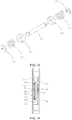
- FIG. 1 illustrates an exploded view of an electronic device, in accordance with an embodiment of the present disclosure.
- the electronic devices can be a mobile terminal 900, the mobile terminal is described as an example in the present embodiment.
- the electronic device can be, for example, smart mobile phones, tablets (PDA), laptops, etc.
- the mobile terminal 900 may include a housing assembly 100.
- the housing assembly 100 may include a first housing 10, a second housing 20 and a connecting module 30.
- the connecting module 30 may be located between the first housing 10 and the second housing 20.
- the connecting module 30 can be configured for coupling the first housing 10 to the second housing 20.
- the second housing 20 can be rotated with respect to the first housing 10 via the connecting module 30.
- the housing assembly 100 can be in a folded configuration, an angular configuration or an unfolded mold.
- the second housing 20 can be rotated with respect to the first housing 10, and then be turned over and stacked onto the first housing 10.
- the first housing 10 and the second housing 20 can be substantially arranged in a plane.
- the angular configuration is a status between the unfolded configuration and the folded configuration.
- the first housing 10 and the second housing 20 may form an angle between 0 and 180°.
- the first housing 10 and the second housing 20 may form an angle more than 180°.
- the connecting module 30 may be flexible or bendable, or even foldable.
- the connecting module 30 When the connecting module 30 is bended, the housing assembly 100 can be in the folded configuration or in the angular configuration. When the connecting module 30 is straight, the housing assembly 100 can be in the unfolded configuration.
- the connecting module 30 can also be configured to prevent a detachment of the second housing 20 and the first housing 10 in the folded configuration or the angular configuration.
- the connecting module 30 may include a connecting member 31 and a coupling member 32.
- the connecting member 31 is bendable, and even foldable.
- the first housing 10 and the second housing 20 can be angular or stacked by bending the connecting member 31.
- the first housing 10 and the second housing 20 can be arranged in a plane.
- the coupling member 32 of the connecting module 30 may also be bendable, and even foldable. In the folded configuration, the coupling member 32 can be folded to support the folded connecting member 31. In the unfolded configuration, the coupling member 32 can also be unfolded to support the unfolded connecting member 31.
- the coupling member 32 may be slidably coupled to the first housing 10 and the second housing 20. From the unfolded configuration to the folded configuration, the coupling member 32 can slide towards the first housing 10 and the second housing 20. For example, the coupling member 32 can slide into the first housing 10 and the second housing 20. Otherwise, from the unfolded configuration to the folded configuration, the coupling member 32 can slide away from the first housing 10 and the second housing 20. For example, the coupling member 32 can slide out of the first housing 10 and the second housing 20. In another example, the coupling member 32 may be slidably coupled to one of the first housing 10 and the second housing 20.
- the coupling member 32 can slide towards one of the first housing 10 or the second housing 20. For example, the coupling member 32 can slide into one of the first housing 10 and the second housing 20. From the unfolded configuration to the folded configuration, the coupling member 32 can slide away from one of the first housing 10 or the second housing 20. For example, the coupling member 32 can slide out of the first housing 10 and the second housing 20.
- the housing assembly 100 can be configured to install a display device 200 including a flexible display panel 40.
- the housing assembly 100 can also be configured to protect other components such as an electronic component group 300.
- the first housing 10 and the second housing 20 of the housing assembly 100 may be made of a rigid material.
- the housing assembly 100 can provide support and protection to the flexible display panel 40.
- the flexible display panel 40 may include a first portion 41, a second portion 42 and a third portion 43.
- the third portion 43 can be located between the first portion 41 and the second portion 42.
- One side of the third portion 43 can be coupled to the first portion 41, the other side of the third portion 43 can be coupled to the second portion 42.
- the first housing 10 can be configured for supporting the first portion 41
- the second housing 20 can be configured for supporting the second portion 42.
- the connecting module 30 can be configured for supporting the third portion 43.
- the connecting module 30 includes the connecting member 31 and the coupling member 32.
- the connecting member 31 can be located between the first housing 10 and the second housing 20. One side of the connecting member 31 is coupled to the first housing 10, the other side of the connecting member 31 is coupled to the second housing 20.
- the coupling member 32 may face the connecting member 31.
- the coupling member 32 can be located between the first housing 10 and the second housing 20. One side of the coupling member 32 is slidably coupled to the first housing 10, the other side of the coupling member 32 is slidably coupled to the second housing 20.
- the coupling member 32 can be configured to support the connecting member 31. In the folded configuration, the coupling member 32 can be in contact with the connecting member 31 to support the connecting member 31.
- the first housing 10, as illustrated in FIG.2-FIG.3 may include a first front cover 11 and a first rear cover 12.
- the first rear cover 12 can be coupled with the first front cover 11 to form a first accommodating cavity 13.
- the first accommodating cavity 13 can be configured for accommodating the electronic component group 300 (as illustrated in FIG. 1 ).
- the first front cover 11 may have a first supporting surface 111.
- the first supporting surface 111 can be configured for supporting the first portion 41 of the flexible display panel 40.
- the first rear cover 12 can be coupled to the first front cover 11 and located on a side of the first front cover 11 opposite to the first supporting surface 111.
- the first rear cover 12 may have a first rear surface 121 far away from the first front cover 11.
- the first housing 10 may include a first interior portion 14 and a first exterior portion 15.
- the first interior portion 14 can be coupled to the connecting module 30, and the first exterior portion 15 can be far away from the connecting module 30.
- the first interior portion 14 is coupled to the connecting member 31 and the coupling member 32.
- the connecting member 31 is fixed to the first interior portion 14, and the coupling member 32 is slidably coupled to the first interior portion 14.
- the first exterior portion 15 is configured to be coupled to the first portion 41 of the flexible display panel 40.
- an edge of the first portion 41 far away from the second portion 42 is coupled to the first exterior portion 15 of the first housing 10.
- the first portion 41 of the flexible display panel 40 can be positioned on the first supporting surface 111.
- the first housing 10 can support the first portion 41 of the flexible display panel 40 effectively.
- the coupling member 32 is slidably coupled to the first interior portion 14.
- the first interior portion 14 may have a first groove 16.
- the coupling member 32 can be partially received in the first groove 16.
- the coupling member 32 can slide with respect to the first interior portion 14.
- the coupling member 32 can slide either into or out of the first groove 16. As a result, the coupling member 32 will not be compressed by the first housing 10 from the unfolded configuration to the folded configuration, thereby avoiding a deformation of the coupling member 32.
- the coupling member 32 can have a groove for partially receiving the first interior portion 14.
- the first interior portion 14 can be partially received in the groove of the coupling member 32.
- the coupling member 32 can slide with respect to the first interior portion 14.
- the first interior portion 14 can slide either into or out of the groove of the coupling member 32.
- the first groove 16 includes two first guiding grooves 141 and a number of first auxiliary guiding grooves 142.
- the first auxiliary guiding grooves 142 are arranged between the two first guiding grooves 141.
- the two first guiding grooves 141 and the first auxiliary guiding grooves 142 extend through the first interior portion 14, thereby forming a number of openings 147 at first interior portion 14.
- Each of the two first guiding grooves 141 extends from the first interior portion 14 toward the first exterior portion 15.
- Each of the first auxiliary guiding grooves 142 also extends from the first interior portion 14 toward the first exterior portion 15.
- An extending direction of each of the two first guiding grooves 141 is substantially parallel to an extending direction of each of the first auxiliary guiding grooves 142.
- the two first guiding grooves 141 are configured to guide the coupling member 32.
- the coupling member 32 can slide along the extending direction of the two first guiding grooves 141, thereby avoiding a movement along a direction perpendicular to the extending direction of the first guiding grooves 141 (i.e., a longitudinal direction of the first interior portion 14).
- the first auxiliary guiding grooves 142 are also configured to guide the coupling member 32.
- the coupling member 32 can slide along the extending direction of the first auxiliary guiding grooves 142, thereby avoiding a movement along a direction perpendicular to the extending direction of the first auxiliary guiding grooves 142 (i.e., a longitudinal direction of the first interior portion 14).
- the coupling member 32 can slide with respect to the first interior portion 14 of the first housing 10 smoothly.
- the first interior portion 14 defines two first mounting grooves 143, thereby forming a first mounting portion 144 between the two first mounting grooves 143.
- the first front cover 11 has a first inner sidewall 112 on the first mounting portion 144.
- the two first mounting grooves 143 are located at two ends of the first inner sidewall 112.
- the two first mounting grooves 143 are arranged along a longitudinal direction of the first inner sidewall 112.
- the first housing 10 includes a number of first bearings 145 (for example three bearings 145 are illustrated in FIG. 4 ) located in each of the two first mounting grooves 143.
- the first housing 10 further includes two second bearings 146 disposed on the first inner sidewall 112 face to face. The two second bearings 146 are separated along the longitudinal direction of the first inner sidewall 112.
- the first housing 10 may include two first supporters 17 and a first auxiliary supporter 18.
- the two first supporters 17 can be mounted in the two first mounting grooves 143 one by one.
- the first auxiliary supporter 18 can be mounted on the first mounting portion 144.
- each of the two first supporters 17 is installed into the corresponding first mounting groove 143 and coupled to the first bearings 145 by screws.
- the first rear cover 12 may be configured to support the first supporter 17 exposed from the first front cover 11.
- the first auxiliary supporter 18 is coupled to the first mounting portion 144.
- first auxiliary supporter 18 is coupled to the one of the two second bearings 146 by screw; the other end of the first auxiliary supporter 18 is coupled to the other of the two second bearings 146 by screw.
- one of the two first supporters 17 is also coupled to one of the two second bearings 146 by screw; the other of the two first supporters 17 is also coupled to the other of the two second bearings 146 by screw.
- the first housing 10 can have a simple structure and the structure strength of the first housing 10 can be further enhanced.
- Each of the two first supporters 17 can have one first guiding groove 141 formed therein.
- the first auxiliary guiding grooves 142 can be formed in the first auxiliary supporter 18.
- the coupling member 32 can pass through the two first supporters 17 and the first auxiliary supporter 18 to be partially received in the two first guiding grooves 141 and the first auxiliary guiding grooves 142 and can slide along the two first guiding grooves 141 and the first auxiliary guiding grooves 142. It is easy to assemble the two first supporters 17 and the first auxiliary supporter 18 with the coupling member 32. Otherwise, it is also easy to disassemble the two first supporters 17 and the first auxiliary supporter 18 from the first front cover 11 to be repaired.
- the first housing 10 can be rotated with respect to the second housing 20 by the coupling member 32.
- the coupling member 32 can slide with respect to the first interior portion 14 of the first housing 10.
- a sliding distance of the coupling member 32 relative to the first interior portion 14 can be determined by a rotating angle of the first housing 10 relative to the second housing 20. In general, the larger the rotating angle is, the longer the sliding distance of the coupling member 32 is.
- the mobile terminal 900 is in the folded configuration.
- the first housing 10 can be stacked onto the second housing 20 so as to fold the mobile terminal 900.
- the coupling member 32 may slide from the first interior portion 14 to the first exterior portion 15. That is, the coupling member 32 may slide into the first housing 10.
- the coupling member 32 may stop sliding from the first interior portion 14 to the first exterior portion 15 until the first housing 10 is stacked onto the second housing 20.
- the first guiding grooves 141 may have a predetermined length along a direction from the first interior portion 14 to the first exterior portion 15(i.e., the extending direction of the first guiding grooves 141).
- the predetermined length is represented by H.
- the predetermined length is more than the sliding distance of the coupling member 32 relative to the first interior portion 14.
- the coupling member 32 sliding into the first guiding grooves 141 will not be in contact with the first front cover 11.
- the coupling member 32 sliding into the first guiding grooves 141 will not damage the first front cover 11.
- the mobile terminal 900 is in the unfolded configuration. From the folded configuration to the unfolded configuration, the first housing 10 may be rotated with respect to the second housing 20. And then, the first housing 10 and the second housing 20 are substantially in a plane. During a process from the folded configuration to the unfolded configuration, the coupling member 32 may slide from the first exterior portion 15 to the first interior portion 14.
- the coupling member 32 may slide away from the first exterior portion 15. Furthermore, the first housing 10 can be continually rotated with respect to the second housing 20 of the mobile terminal 900 in the unfolded configuration. Thus, the mobile terminal 900 can be from the unfolded configuration to the angular configuration.
- the coupling member 32 may continually slide from the first exterior portion 15 to the first interior portion 14. A distance of the first interior portion 14 (i.e., the openings 147) and a side of the coupling member 32 in the angular configuration is nearer than a distance of the first interior portion 14 (i.e., the openings 147) and the side of the coupling member 32 in the unfolded configuration.
- each of the two the first supporters 17 includes the first blocking element 19.
- the first blocking element 19 is configured to block the coupling member 32 to be detached from the first guiding grooves 141 of the first interior portion 14 of the first housing 10.
- the first housing 10 may include two first blocking elements 19.
- the two first blocking elements 19 can be configured to block two ends of a side of the coupling member 32 to be detached from the first housing 10.
- a blocking element may be not necessary for the first auxiliary supporter 18.
- the first auxiliary supporter 18 can have a simple structure..
- the first housing 10 may further include a first blocking element 19.
- the first blocking element 19 is configured to block the coupling member 32 sliding towards to the first interior portion 14. Thus, the coupling member 32 will not be detached from the first interior portion 14 of the first housing 10.
- the first housing 10 may further include at least one first locating element 110.
- a location of the coupling member 32 relative to the first housing 10 can be fixed by the first locating element. That is, the first locating element 100 is configured for locating a location of the first connection part 3211 along the sliding direction of first connection part 3211.
- An angle between the first housing 10 and the second housing 20 of the mobile terminal 900 in the angular configuration is depended on the location of the coupling member 32 relative to the first housing 10. It is noted that, the angle between the first housing 10 and the second housing 20 of the mobile terminal 900 can be in a range from 0 to 240°. For example, the angle can be 15°, 26°, 30°, 38°, 109°, 120°, or 201°.
- the first locating element 110 is disposed on the first supporter 17.
- the first locating element 110 is configured to locate the coupling member 32 in the first guiding groove 141.
- the coupling member 32 can be located at a predetermined location relative to the first housing 10.
- two first locating elements 110 can be disposed on the first supporter 17. That is, the first locating element 110 may be not necessary for the first auxiliary supporter 18.
- the first housing 10 can have a simple structure.
- Each of the first locating element 110 may include a locating pin 1101 and a compressible elastic unit 1102.
- the compressible elastic unit 1102 can be a spring.
- the compressible elastic unit 1102 is disposed in the through-hole 17122 and is configured for providing a force to the locating pin 1101 to away from a shielding plate 1717 of a first supporter 17 (i.e., towards the first sliding plate 3211).
- the locating pin 1101 is inserted in the compressible elastic unit 1102.
- the locating pin 1101 can slide away from the shielding plate 1717 or towards the shielding plate 1717.
- the compressible elastic unit 1102 provides a force to the locating pin 1101 so that the locating pin 1101 can slide away from the shielding plate 1717.
- the locating pin 1101 can be in contact with the coupling member 32.
- the locating pin 1101 can be located in a recess 325 (as illustrated in FIG. 14 ) of the coupling member 32.
- the coupling member 32 in the first guiding grooves 141 can stop sliding.
- the end of the locating pin 1101 is in contact with the sliding surface 3221(as illustrated in FIG. 14 ) of the coupling member 32, the compressible elastic unit 1102 can be still compressed and provide a force perpendicular to the extending direction of the first guiding grooves 141 to the locating pin 1101.
- the locating pin 1101 can slide on the sliding surface 3221.
- the coupling member 32 in the first guiding groove 141 can slide.
- the first housing 10 can include a supporter (i.e., one of the first supporter 17 and the first auxiliary supporter 18, or other supporters with different structure) for coupling to the coupling member 32.
- the coupling member 32 can include a sliding plate (i.e., one of the first sliding plate 3213 and the first auxiliary sliding plate 3214, or other sliding plate with different structure) for coupling to the first housing 10.
- the second housing 20 includes a second front cover 21 and a second rear cover 22.
- the second rear cover 22 is coupled to the second front cover 21 to form a second accommodating cavity 23.
- the second accommodating cavity 23 is configured for accommodating the electronic component group 300 (as illustrated in FIG. 1 ).
- the second front cover 21 includes a second supporting surface 211.
- the second supporting surface 211 is configured for supporting the second portion 42 of the flexible display panel 40 (as illustrated in FIG. 1 ).
- the second rear cover 22 may be coupled to the second front cover 21 and located on a side of the second front cover 21 opposite to the second supporting surface 211.
- the second rear cover 22 has a second rear surface 221 far away from the second front cover 21.
- the first supporting surface 111 and the second supporting surface 221 are configured for supporting the flexible display panel 40.
- the second housing 20 includes a second interior portion 24 and a second exterior portion 25.
- the second interior portion 24 is coupled to the connecting module 30, and the second exterior portion 25 is far away from the connecting module 30.
- the second interior portion 24 is coupled to the connecting member 31 and the coupling member 32.
- the connecting member 31 is fixed to the second interior portion 24, and the coupling member 32 is slidably coupled to the second interior portion 24.
- the second exterior portion 25 is configured to be coupled to the second portion 42 of the flexible display panel 40.
- an edge of the second portion 42 far away from the first portion 41 is coupled to the second exterior portion 25 of the second housing 20.
- the second portion 42 of the flexible display panel 40 is positioned on the second supporting surface 211.
- the second housing 20 can support the second portion 42 of the flexible display panel 40 effectively.
- the second housing 20 is similar to the first housing 10, according to the description of the first housing 10 (including the first supporter 17, the first auxiliary supporter 18, the first blocking element 19, the first locating member 110, etc.), the corresponding structure of the second housing 20 can be understood and not described here.
- the second housing 20 may include a second groove similar to the first groove 16 for partially receiving the coupling member 32. That is, the second housing 20 is configured for receiving the second connection part 3212 of the coupling member 32.
- the coupling member 32 can be partially received in at least one of the first groove 16 and the second groove and is slidable with respect to the first housing 10 and the second housing 20.
- the mobile terminal 900 can be in the folded configuration, the angular configuration, or the unfolded configuration. From the unfolded configuration to the folded configuration or the angular configuration, the first housing 10 and the second housing 20 are close to each other by bending the connecting member 31 of the connecting module 30. From the folded configuration to the unfolded configuration or the angular configuration, the first housing 10 and the second housing 20 are far away from each other.
- the connecting member 31 is configured to couple the first housing 10 to the second housing 20.
- the connecting member 31 may include a first connecting portion 311, a second connecting portion 312 and a body portion 318 between the first connecting portion 311 and the second connecting portion 312.
- the first connecting portion 311 and the second connecting portion 312 are located at two opposite sides of a longitudinal central line of the body portion 318.
- the first connecting portion 311 is configured to be coupled to the first housing 10, and the second connecting portion 312 is configured to be coupled to the second housing 20.
- the connecting member 31 is bendable, and even foldable.
- the first housing 10 and the second housing 20 can be angular or stacked by bending the connecting member 31.
- the first connecting portion 311, the second connecting portion 312 and the body portion 318 can be integrally formed. In some embodiments, the first connecting portion 311, the second connecting portion 312 and the body portion 318 can be individually formed and coupled.
- the body portion 318 may include a first connecting side 313 and a second connecting side 313'.
- the first connecting portion 311 and the second connecting portion 312 are located two opposite sides of the connecting member 31.
- the first connecting side 313 and the second connecting side 313' are opposite and located between the first connecting portion 311 and the second connecting portion 312.
- a length of the first connecting portion 311 is equal to a length of the second connecting portion 312.
- the length of the first connecting portion 311 is more than a length of each of the first connecting side 313 and the second connecting side 313'.
- the first connecting portion 311 is configured to be coupled to the first interior portion 14 of the first housing 10 (as illustrated in FIG. 2 ).
- the second connecting portion 312 is configured to be coupled to the second interior portion 24 of second housing 20.
- the first connecting portion 311 is welded to the first interior portion 14, i.e., the first connecting portion 311 is welded to the second cover plate 182 and the first cover plate 172.
- the second connecting portion 312 is welded to the second interior portion 24.
- the body portion 318 defines a number of through holes 314 therein.
- the through holes 314 are arranged along a longitudinal direction of the body portion 318.
- the through holes 314 are equally spaced.
- Each of the through holes 314 is strip-shaped, a longitudinal direction of each of the through holes 314 is perpendicular to a longitudinal direction of the body portion 318. That is, the longitudinal direction of each of the through holes 314 is substantially parallel to the first connecting side 313 and the second connecting side 313'.
- the through holes 314 can reduce an elastic stress of the connecting member 31 during bending the body portion 318. Thus, a force applied to the flexible display panel 40 by the connecting member 31 can be reduced. It is noted that, a configuration of each of the through holes 314 can be circle.
- the first connecting portion 311 and the second connecting portion 312 may be close to each other by bending the body portion 318.
- the first housing 10 can move with the first connecting portion 311, and the second housing 20 can move with the second connecting portion 312.
- the first housing 10 can be rotated relative to the second housing 20 to be close to each other, and then the mobile terminal 900 is folded by bending the body portion 318. Otherwise, the first housing 10 can be rotated relative to the second housing 20 to be far away from each other, and then the mobile terminal 900 is unfolded.
- the coupling member 32 can be also folded or unfolded during bending or unbending the body portion 318 correspondingly.
- the first connecting side 313 and the second connecting side 313' are overlapped with two opposite sides of the flexible display panel 40.
- the connecting member 31 can support the flexible display panel 40 and the housing assembly 100 can have a good appearance.
- the connecting member 31 can be made of an elastic steel sheet.
- the connecting member 31 can support the flexible display panel 40 effectively.
- first connecting portion 311 of the connecting member 31 can be coupled to the first housing 10 by means of screw.
- the second connecting portion 312 of the connecting member 31 can be coupled to the first housing 10 by means of screw.
- the body portion 318 may define a number of welding holes 315 therein.
- the welding holes 315 can be arranged along a longitudinal direction of the body portion 318.
- Each of the welding holes 315 has a geometric center, the geometric centers of the welding holes 315 are arranged along the longitudinal central line of the body portion 318.
- the welding holes 315 are configured for welding the coupling member 32 to the body portion 318.
- the coupling member 32 welded to the body portion 318 can be prevented from a movement along a direction perpendicular to the longitudinal direction of the body portion 318 (i.e., perpendicular to a sliding direction of the coupling member 32) with respect to the connecting member 31.
- the coupling member 32 may include a first connection part 3211 (a part in a region defined by a dotted line) and a second connection part 3212 (a part in a region defined by a dotted line).
- the first connection part 3211 is slidably coupled to the first housing 10
- the second connection part 3212 is slidably coupled to the second housing 20.
- the first connection part 3211 may include two first sliding plates 3213 and a number of first auxiliary sliding plates 3214 located between the two first sliding plates 3213.
- the two first sliding plates 3213 are located in the two first guiding grooves 141 respectively and can slide in the corresponding first guiding groove 141 (as illustrated in FIG.
- Each of the first auxiliary sliding plates 3214 is located in the corresponding first auxiliary guiding groove 142 and can slide in the corresponding first auxiliary guiding groove 142 with respect to the first housing 10.
- a longitudinal direction of each of the two the first sliding plates 3213 is substantially parallel to the longitudinal direction of the guiding bar 173. Additionally, each of the two first sliding plates 3213 is substantially parallel to the first supporting surface 111.
- Each of the two first sliding plate 3213 includes two sliding surfaces 3221. The two sliding surfaces 3221 are located on two opposite sides of the first sliding plate 3213. The two sliding surfaces 3221 are parallel to each other, and parallel to the longitudinal direction of the first sliding plate 3213.
- the two side surfaces 3221 are in contact with the surfaces of the guiding bar 173 in the two grooves 175.
- the first sliding plate 3211 can slide in the first guiding groove 141 formed by the grooves 175 of the two guiding bars 173.
- a sliding direction of the first connection part 3211 with respect to the first housing 10 is perpendicular to the hinge shaft 329.
- Each of the first auxiliary sliding plate 3214 is also substantially parallel to the first supporting surface 111.
- a longitudinal direction of each of the first auxiliary sliding plate 3214 is substantially parallel to the longitudinal direction of the first sliding plate 3213.
- the first auxiliary sliding plates 3214 are spaced and arranged between the two first sliding plate 3213.
- the first auxiliary sliding plate 3214 can slide in the first auxiliary guiding groove 142.
- a lateral surface of the first auxiliary sliding plate 3214 is in contact with the first auxiliary guiding grooves 142.
- the first auxiliary sliding plate 3214 can slide with respect to the first housing 10 smoothly.
- a sliding direction of the second connection part 3212 with respect to the second housing 20 is substantially perpendicular to the hinge shaft 329.
- the second connection part 3212 may include two second sliding plates 3215 and a number of second auxiliary sliding plates 3216.
- the second auxiliary sliding plates 3216 are located between the two second sliding plates 3215.
- the two second sliding plates 3215 are slidably coupled to the second housing 20 (i.e., the second supporter of the second housing 20, the second supporter is similar to the first supporter 17 and not described here).
- the two second sliding plates 3215 can slide in two first guiding grooves 141 defined in the second supporter of the second housing 20.
- the second auxiliary sliding plates 3216 are slidably coupled to the second housing 20 (i.e., the second auxiliary supporter of the second housing 20, the second auxiliary supporter is similar to the first auxiliary supporter 18 and not described here).
- the second auxiliary sliding plates 3216 can slide in a number of first auxiliary guiding grooves 142 defined in the second auxiliary supporter of the second housing 20.
- Each of the second sliding plates 3215 is similar to the first sliding plate 3213, and each of the second auxiliary sliding plates 3216 is similar to the first auxiliary sliding plate 3214.
- the first housing 10 may include the first blocking element 19 (as illustrated in FIG. 5 and FIG. 6 ) so as to prevent a detachment of the first connection part 3211 of the coupling member 32 and the first housing 10 and a detachment of the second connection part 3212 of the coupling member 32 and the second housing 20.
- the first connection part 3211 may define a first blocking groove 324.
- the first blocking element 19 of the first housing 10 is disposed in the first blocking groove 324 and can slide along a longitudinal direction of the first blocking groove 324.
- the second connection part 3212 may define a second blocking groove coupled to the second blocking element of the second housing 20.
- the second blocking element can be disposed at the second supporter, the second sliding plate of the second connection part 3212 can define a second blocking groove.
- the second blocking element is slidably disposed in the second blocking groove, a longitudinal direction of the second blocking groove is parallel to a sliding direction of the second sliding plate of the second connection part 3212.
- the second blocking groove is similar to the first blocking groove 324, and the second blocking member is similar to the first blocking element 19.
- a longitudinal direction of the second blocking groove is parallel to a sliding direction of the second sliding plate 3212.
- the first blocking groove 324 is defined in the first sliding plate 3213.
- a profile of the first blocking groove 324 is runway-shaped.
- the first blocking groove 324 is substantially striped-shaped.
- Each of two ends of the first blocking groove 324 has a profile of semicircle-shaped.
- the longitudinal direction of the first blocking groove 324 is substantially parallel to the longitudinal direction of the first sliding plate 3213 (i.e., a sliding direction of the first sliding plate 3213 of the first connection part 3211).
- the first blocking element 19 can penetrate through the first blocking groove 324 and slide in the first blocking groove 324 along the longitudinal direction of the first blocking groove 324.
- a diameter of the blocking rod 191 of the first blocking element 19 is substantially equal to a width of the first blocking groove 324.
- the blocking rod 191 can only slide in the first blocking groove 324 along the longitudinal direction of the first blocking groove 324. That is, the blocking rod 191 can not slide in the first blocking groove 324 along a direction perpendicular to the longitudinal direction of the first blocking groove 324.
- the blocking rod 191 is located at the end of the first blocking groove 324 towards the first exterior portion 15.
- the first sliding plate 3213 can not slide towards the first exterior portion 15 due to the blocking rod 191.
- the first sliding plate 3213 is prevented from sliding out of the first guiding groove 141.
- the coupling member 32 will not be detached from the first housing 10 and the second housing 20.
- a first connection part 3211 may include a first sliding plate 3213.
- the first sliding plate 3213 can have a first blocking rod 324' disposed thereon.
- the first housing 10 may define a blocking groove The first locating rod 324' can be slidably located in the blocking groove.
- the first housing 10 may include the first locating element 110 (as illustrated in FIG. 5 and FIG. 6 ) so as to locate the first connection part 3211 and the second connection part 3212 in a predetermined position.
- the mobile terminal 900 can be in the angular configuration with a predetermined angel.
- the first connection part 3211 may define a number of first locating recesses 325.
- a sliding distance of the first connection part 3211 of the coupling member 32 relative to the first housing 10 can be determined by a position of each of the first locating recesses 325. The sliding distance can be depended on an angle between the first housing 10 and the second housing 20 of the mobile terminal 900 in the angular configuration.
- the first locating element 110 can be located into one of the first locating recesses 325.
- the second connection part 3212 may define a number of second locating recesses
- the second housing 20 may include a second locating element coupled to one of the second locating recesses.
- the second locating member can be disposed at the second supporter.
- the second sliding plate defines a number of second locating recesses.
- the second locating member is configured to couple to one of the number of second locating recesses so that the coupling member 32 can stop sliding with respect to the second housing 20.
- the second locating recesses are similar to the first locating recesses 325, and the second locating element is similar to the first locating element 110.
- the second locating element is configured for locating a location of the second connection part 3212 along the sliding direction of second connection part 3212.
- the first locating recesses 325 are defined at the two sliding surfaces 3221.
- the first locating recesses 325 are spaced and arranged along the longitudinal direction of the first sliding plate 3213 (i.e., the sliding direction of the first sliding plate 3213).
- the first housing 10 can be rotated with respect to the second housing 20.
- the first connection part 3211 of the coupling member 32 can slide with respect to the first housing 10.
- the first sliding plate 3213 can slide in the first guiding groove 141 in a condition of a force parallel to the longitudinal direction of the first sliding plate 3213.
- the first connection part 3211 of the coupling member 32 can slide until the locating pin 1101 enters into the locating recess 325.
- the compressible elastic unit 1102 can provide a force perpendicular to the longitudinal direction of the first sliding plate 3213 to the locating pin 1101.
- the locating pin 1101 can be received in the locating recess 325.
- the first sliding plate 3213 stop sliding in the first guiding groove 141.
- the angle of the first housing 10 and the second housing 20 can be maintained.
- the mobile terminal 900 can be in the angular configuration.
- the coupling member 32 includes a linkage part 326 (a part located in a region defined by a dotted line in FIG. 13 ).
- the linkage part 326 includes at least one first hinge element 327, at least one second hinge element 328 and a hinge shaft 329 for pivotally coupling the first hinge element 327 and the second hinge element 328.
- the first hinge element 327 can be rotated with respect to the second hinge element 328 by the hinge shaft 329.
- the first connection part 3211 and the second connection part 3212 can be either close to or far away from each other by a rotation of one of the first hinge element 327 of the linkage part 326 and the second hinge element 328 of the linkage part 326 around the hinge shaft 329.
- the first connection part 3211 is configured to be slidably coupled the first housing 10
- the second connection part 3212 is configured to be slidably coupled the second housing 20.
- An arrangement direction of the two first sliding plate 3213 of each of the first connection part 3211 is substantially parallel to the hinge shaft 329.
- the first connection part 3211 and the second connection part 3212 of the coupling member 32 are symmetrical with respect to the hinge shaft 329.
- a distance of the hinge shaft 329 and the first housing 10 is substantially equal to a distance of the hinge shaft 329 and the second housing 20.
- the hinge shaft 329 is substantially overlapped with a geometric central line of the connecting member 31.
- the linkage part 326 can be folded and unfolded by rotating one of the first hinge element 327 and the second hinge element 328 around the hinge shaft 329.
- the linkage part 326 can be configured to support the connecting member 31.
- the linkage part 326 may include a number of first hinge elements 327 and a number of second hinge elements 328.
- the first hinge elements 327 are arranged along the longitudinal direction of the hinge shaft 329.
- the second hinge elements 328 are arranged along the longitudinal direction of the hinge shaft 329.
- the first hinge elements 327 and the second hinge elements 328 are alternatively arranged along the longitudinal direction of the hinge shaft 329.
- the linkage part 326 may include one first hinge element 327 and one second hinge element 328.
- the first hinge element 327 can define a groove
- the second hinge element 328 can have a protrusion received into the groove.
- the first shaft 329 may pass the groove and penetrate the protrusion so that the hinge shaft 329 can pivotally couple the first hinge element 327 and the second hinge element 328.
- the first hinge element 327 may include a first interior side 3271, a first exterior side 3272 and two first sidewalls 3273.
- the first interior side 3271 and the first exterior side 3272 are located at two opposite sides of the first hinge element 327.
- the two first sidewalls 3273 are located on two opposite sides of the first hinge element 327.
- Each of the two first sidewalls 3273 is adjacent to the first interior side 3271 and the first exterior side 3272.
- One of the two first sidewalls 3273 defines a shaft hole near to the first interior side 3271.
- the hinge shaft 329 can pass through the shaft hole.
- the hinge shaft 329 can penetrate through first interior side 3271 of the first hinge element 327.
- the first hinge element 327 can be rotated around the hinge shaft 329.
- the first interior side 3271 is rotatably coupled to the hinge shaft 329.
- the first interior side 3271 can have a curved surface.
- a profile of a cross-section of the curved surface is semicircle-shaped.
- a central axis of the semicircle-shaped profile can be overlapped with the axis of the hinge shaft 329.
- the first exterior side 3272 can have a similar structure so as to avoid an interference caused by the first exterior side 3272 to the other component.
- the first exterior side 3272 can also be pivotally coupled with the first connection part 3211.
- the first hinge element 327 can be made of metal.
- first hinge element 327 can have a good appearance.
- first hinge element 327 can be curved.
- the first hinge element 327 can provide a support to the connecting member 31.
- the second hinge element 328 may include a second interior side 3281, a second exterior side 3282 and two second sidewalls 3283.
- the second interior side 3281 and the second exterior side 3282 are located at two opposite sides of the second hinge element 328.
- the two second sidewalls 3283 are located on two opposite sides of the second hinge element 328.
- Each of the two second sidewalls 3283 is adjacent to the second interior side 3281 and the second exterior side 3282.
- One of the two second sidewalls 3283 defines a shaft hole near to the second interior side 3281.
- the hinge shaft 329 can pass through the shaft hole.
- the hinge shaft 329 can penetrate through second interior side 3281 of the second hinge element 328.
- the second interior side 3281 is rotatably coupled to the hinge shaft 329.
- the second sidewall 3283 is substantially parallel to the first sidewall 3273.
- a gap is formed between the second sidewall 3283 and the first sidewall 3273.
- the second hinge element 328 can be rotated around the hinge shaft 329 with respect to the first hinge element 327 smoothly.
- the second interior side 3281 can have a curved surface.
- a profile of a cross-section of the curved surface is semicircle-shaped.
- a central axis of the semicircle-shaped profile can be overlapped with the axis of the hinge shaft 329.
- the second exterior side 3282 can have a similar structure so as to avoid an interference caused by the second exterior side 3282 to the other component.
- the second exterior side 3282 can also be pivotally coupled with the second connection part 3212.
- the second hinge element 328 can be made of metal. An anodic oxidation treatment can be applied to a surface of the second hinge element 328. Thus, the second hinge element 328 can have a good appearance.
- the coupling member 32 may include a damping mechanism 33.
- the damping mechanism 33 is configured to provide a damping force to the first hinge element 327 and the second hinge element 328 during rotating the first hinge element 327 with respect to the second hinge element 328. In a condition of the damping force, a position of the first hinge element 327 relative to the second hinge element 328 can be maintained. Thus, the angle of the first housing 10 and the second housing 20 can be maintained. That is, the mobile terminal 900 can be maintained in the folded configuration or the angular configuration.
- the damping mechanism 33 may include a damping member 331.
- the damping member 331 includes a first damping ring 3311 and a second damping ring 3312.
- the first damping ring 3311 is sleeved on the hinge shaft 329 and is coupled to the first hinge element 327.
- the first damping ring 3311 can be rotated with the first hinge element 327.
- the second damping ring 3312 is sleeved on the hinge shaft 329 and is coupled to the second hinge element 328.
- the second damping ring 3312 can be rotated with the second hinge element 328.
- the first damping ring 3311 has a rough surface
- the second damping ring 3312 also has a rough surface.
- the first damping ring 3311 is in contact with the second damping ring 3312 to generate a damping force.
- the first damping ring 3311 is made of wear resistant material.
- the second damping ring 3312 is also made of wear resistant material.
- the damping mechanism 33 may include a number of damping members 331. Each of the damping members 331 is located between the first hinge element 327 and the second hinge element 328 adjacent to the first hinge element 327.
- Each of the first damping rings 3311 is in contact with the corresponding second damping ring 3312.
- a damping force can be generated due to a rotation of the first damping ring 3311 with respect to the second damping ring 3312.
- the first damping ring 3311 is fixed to the first sidewall 3273 of the first hinge element 327
- the second damping ring 3312 is fixed to the second sidewall 3283 of the second hinge element 328 adjacent to the first hinge element 327 along the hinge shaft 329.
- the damping force generated can be transmitted to the first hinge element 327 and the second hinge element 328.
- the first hinge element 327 and the second hinge element 328 can stop rotating in a condition of the damping force.
- the first hinge element 327 can be static relative to the second hinge element 328.
- the connecting member 31 can maintain a predetermined configuration.
- a position of the first housing 10 relative to the second housing 20 is not changed.
- the first hinge element 327 can be rotated relative to the second hinge element 328.
- the connecting member 31 can be bent and the configuration of the connecting member 31 is changed.
- the first housing 10 can also be rotated relative to the second housing 20. That is, a position of the first housing 10 relative to the second housing 20 can be changed.
- the damping member 331 can further include the first elastic ring 3313, a second elastic ring 3314, a first clasp ring 3315 and a second clasp ring 3316.
- the first elastic ring 3313 is sleeved on the hinge shaft 329, and is located between the first sidewall 3273 of the first hinge element 327 and the first damping ring 3311.
- the second elastic ring 3314 is sleeved on the hinge shaft 329, and is located between the second sidewall 3283 of the second hinge element 328 and the second damping ring 3312.
- the first elastic ring 3313 can apply a force to the first damping ring 3311, and the second elastic ring 3314 can apply a force to the second damping ring 3312.
- the first clasp ring 3315 is also sleeved on the hinge shaft 329.
- the first elastic ring 3313 is compressed and located between the first damping ring 3311 and the first clasp ring 3315.
- the first clasp ring 3315 is configured to block the first elastic ring 3313. That is, the first clasp ring 3315 is configured to prevent the first elastic ring 3313 from moving along the hinge shaft 329.
- the second clasp ring 3316 is also sleeved on the hinge shaft 329.
- the second elastic ring 3314 is compressed and located between the second damping ring 3312 and the second clasp ring 3316.
- the second clasp ring 3316 is configured to block the second elastic ring 3314. That is, the second clasp ring 3316 is configured to prevent the second elastic ring 3314 from moving along the hinge shaft 329.
- the hinge shaft 329 may include a number of short rods. Each of the short rods penetrates the first hinge element 327 and the second hinge element 328.
- the first clasp ring 3315 and the second clasp ring 3316 are sleeved on the short rod and located at two ends of the short rod.
- the first sidewall 3273 defines a first depression 3274
- the second sidewall 3283 defines a second depression 3284.
- the first hinge element 327 has a first inner surface in the first depression 3274
- the second hinge element 328 has a second inner surface in the second depression 3284.
- the first damping ring 3311 is located in the first depression 3274 and the second damping ring 3312 is located in the second depression 3284.
- the first damping ring 3311 is prevented from being rotated relative to the first hinge element 327 in the first depression 3274, and the second damping ring 3312 is prevented from being rotated relative to the second hinge element 328 in the second depression 3284.
- the first elastic ring 3313 is also located in the first depression 3274, and the second elastic ring 3314 is also located in the second depression 3284.
- a gap between the first hinge element 327 and the second hinge element 328 adjacent to the first hinge element 327 along the hinge shaft 329 can be reduced.
- a performance of the linkage part 326 for supporting the connecting member 31 can be improved.
- the first clasp ring 3315 is located at an end of the first depression 3274 far away from the second hinge element 328, and the second clasp ring 3316 is located at an end of the second depression 3284 far away from the first hinge element 327.
- a gap can be formed between the first clasp ring 3315 and the first inner surface of the first hinge element 327, and a gap can be formed between the second clasp ring 3316 and the second inner surface of the second hinge element 328.
- the first elastic ring 3313 will not damage the first hinge element 327
- the second elastic ring 3314 will not damage the second hinge element 328.
- the first elastic ring 3313 can also be a spring
- the second elastic ring 3314 can be a spring.
- the linkage part 326 can further include a third hinge element 333, a fourth hinge element 334, a first auxiliary hinge shaft 335 and a second auxiliary hinge shaft 336.
- the third hinge element 333 can be made of metal.
- An anodic oxidation treatment can be applied to a surface of the third hinge element 333.
- the fourth hinge element 334 can be made of metal.
- An anodico xidation treatment can be applied to a surface of the fourth hinge element 334.
- the fourth hinge element 334 and the first hinge element 327 can have identical appearance.
- the first hinge element 327 can be curved.
- the third hinge element 333 is pivotally coupled with the first exterior side 3271 of the first hinge element 327 by the first auxiliary hinge shaft 335.
- the fourth hinge element 334 is pivotally coupled with the second exterior side 3282 of the second hinge element 328 by the second auxiliary hinge shaft 336.
- the first auxiliary hinge shaft 335 is substantially parallel to the hinge shaft 329.
- the third hinge element 333 includes a third interior side 3331, a third exterior side 3332 and two third sidewalls 3333.
- the third interior side 3331 and the third exterior side 3332 are located at two opposite sides of the third hinge element 333.
- the two third sidewalls 3333 are located on two opposite sides of the third hinge element 333.
- Each of the two third sidewalls 3333 is adjacent to the third interior side 3331 and the third exterior side 3332.
- One of the two third sidewalls 3333 defines a shaft hole near to the third interior side 3331.
- the first auxiliary hinge shaft 335 can pass through the shaft hole.
- the third hinge element 333 can be rotated around the first auxiliary hinge shaft 335.
- the third hinge element 333 is pivotally coupled with the first hinge element 327 by the first auxiliary hinge shaft 335.
- the first auxiliary hinge shaft 335 can pass through the shaft hole formed in the first exterior side 3272 of the first hinge element 327.
- the third coupling member 333 is pivotally coupled with the first hinge element 327 by the first auxiliary hinge shaft 335.
- the third coupling member 333 can be rotated relative to the first hinge element 327.
- the linkage part 326 can further include a number of third hinge elements 333 and a number of first hinge elements 327.
- the third hinge elements 333 and the first hinge elements 327 are arranged alternatively along the first auxiliary hinge shaft 335.
- one of the two third sidewalls 3333 of the third hinge element 333 may have a first extending portion 3334.
- An extending direction of the first extending portion 3334 is substantially parallel to the first auxiliary hinge shaft 335.
- An extending length is substantially equal to a distance of the two first sidewalls 3273 of the two adjacent first hinge elements 327 along the first auxiliary hinge shaft 335.
- the first extending portion 3334 of one of the two adjacent third hinge elements 333 along the first auxiliary hinge shaft 335 is in contact with the third sidewall 3333 of the other of the two adjacent third hinge elements 333 along the first auxiliary hinge shaft 335.
- a contact area of the linkage part 326 and the connecting member 31 can be increased.
- the performance of the linkage part 326 for supporting the connecting member 31 can be improved.
- the first connection part 3211 is coupled to the first hinge element 327 by the third hinge element 333.
- the two first sliding plate 3213 are coupled to the third exterior sides 3332 of the third hinge elements 333 at two ends of the first auxiliary hinge shaft 335 respectively.
- Each of the first sliding plates 3213 can be integrated with the corresponding third hinge element 333 at the end of the first auxiliary hinge shaft 335.
- the third exterior side 3213 has a side surface.
- the side surface is a plane.
- the first sliding plate 3213 is substantially perpendicular to the side surface of the third exterior side 3213.
- the first auxiliary sliding plates 3214 are coupled to the third exterior sides 3332 of the third hinge elements 333 except the third hinge element 333 at the end of the first auxiliary hinge shaft 335.
- the third hinge elements 333 can be slidably coupled to the first housing 10 by the first sliding plate 3213 and the first auxiliary sliding plates 3214.
- the first connection part 3211 of the coupling member 32 can be slidably coupled to the first housing 10.
- the third sidewall 3333 of the third hinge element 333 can be substantially parallel to the first sidewall 3273 of the first hinge element 327.
- a gap can be formed between the third sidewall 3333 of the third hinge element 333 and the first sidewall 3273 of the first hinge element 327 adjacent to the third hinge element 333 along the first auxiliary hinge shaft 335.
- the first hinge element 327 can be rotated relative to the third hinge element 333 smoothly.
- the third interior side 3331 can be have a curved surface.
- a profile of a cross-section of the curved surface is semicircle-shaped.
- a central axis of the semicircle-shaped profile can be overlapped with the axis of the first auxiliary hinge shaft 335.
- the first hinge element 327 and the third hinge element 333 will not be interfered with each other.
- the first extending portion 3334 may have a curved surface facing the first hinge element 327. A profile of a cross-section of the curved surface is also semicircle-shaped.
- the damping mechanism 33 may further include a first auxiliary damping member 332.
- Each of the first auxiliary damping members 332 is located between the first hinge element 327 and the third hinge element 333 adjacent to the first hinge element 327 along the first auxiliary hinge shaft 335.
- the first auxiliary damping member 332 is configured to provide a damping force to the first hinge element 327 and the third hinge element 333 during rotating the first hinge element 327 with respect to the third hinge element 333. In a condition of the damping force, a position of the third hinge element 333 relative to the first hinge element 327 can be maintained. Thus, the angle of the first housing 10 and the second housing 20 can be maintained.
- the first auxiliary damping member 332 is similar to the damping member 331.
- a first elastic ring 3315 of the first auxiliary damping member 332 is sleeved on the first auxiliary hinge shaft 325 and located between the first hinge element 327 and a first damping ring 3311 of the first auxiliary damping member 332.
- a second elastic ring 3314 of the first auxiliary damping member 332 is sleeved on the first auxiliary hinge shaft 325 and located between the third hinge element 333 and the second damping ring 3312 of the first auxiliary damping member 332.
- the fourth hinge element 334 is similar to the third hinge element 333.
- a second extending portion 3344 of the fourth hinge element 334 and the first extending portion 3334 of the third hinge element 333 are in opposite directions.
- the fourth hinge element 334 and the second hinge element 328 are alternatively arranged along the second auxiliary hinge shaft 336.
- the second connection part 3212 of the coupling member 32 can be slidably coupled to the second housing 20.
- the damping mechanism 33 may further include a second auxiliary damping member 340.
- the first housing 10 and the second housing 20 can be in the angular configuration with a predetermined angle.
- the second auxiliary damping member 340 is configured for providing a damping force to the fourth hinge element 334 and the second hinge element 328 to prevent the fourth hinge element 334 from rotating relative to the second hinge element 328.
- the fourth damping member 340 is similar to the first damping member 331.
- the first elastic ring 3313 of the second auxiliary damping member 340 is sleeved on the second auxiliary hinge shaft 326, and is located between the second hinge element 328 and a first damping ring 3311 of the second auxiliary damping member 340.
- a second elastic ring 3314 of the second auxiliary damping member 340 is sleeved on the second auxiliary hinge shaft 326, and is located between the fourth hinge element 334 and a second damping ring 3312 of the second auxiliary damping member 340.
- the first connection part 3211 of the coupling member 32 is slidably coupled to the first housing 10 (see FIG.1 ) and the second connection part 3212 of the coupling member 32 is slidably coupled to the second housing 20 (see FIG.1 ).
- the coupling member 32 is connect to the connecting member 31.
- the coupling member 32 is prevented from sliding along a direction perpendicular to the hinge shaft 329 with respect to the connecting member 31. That is, the coupling member 32 and the connecting member 31 should be slide either from the first interior portion 14 to the first exterior portion 15 together or from the first exterior portion 15 to the first interior portion 14 together.
- the connecting module 30 may further include a positioning member 34.
- the positioning member 34 includes a first end 341 and a second end 342 opposite the first end 341.
- the first end 341 is coupled to the connecting member 31, and the second end 344 is coupled to the coupling member 32.
- the positioning member 34 is configured to prevent the coupling member 32 from moving to the first housing 10 or the second housing 20 with respect to the connecting member 31.
- the first end 341 is coupled to the connecting member 31, and the second end 342 is configured to prevent the coupling member 32 from moving with respect to the connecting member 31.
- a distance of the positioning member 34 and the first housing 10 is substantially equal to a distance of the positioning member 34 and the second housing 20.
- the coupling member 32 is coupled to the connecting member 31 by the positioning member 34. Thus, the coupling member 32 will not move towards the first housing 10 or the second housing 20 relative to the connecting member 31.
- the first end 341 includes a raised portion 343.
- the raised portion 343 is raised far away from the second end 342.
- the second end 342 have a through hole 344.
- a central axis of through hole 344 is substantially perpendicular to a raising direction of the raised portion 343.
- the central axis of through hole 344 is substantially parallel to the hinge shaft 329.
- the connecting member 31 defines a number of welding holes 315.
- Each of the welding holes 315 has a geometric center.
- the geometric centers of the welding holes 315 are arranged along a longitudinal geometric central line of the connecting member 31.
- the raised portion 343 of the positioning member 34 of the first hinge element 327 received in the welding hole 315 and welded to the connecting member 31.
- the first interior side 3271 of the first hinge element 327 have a cutout 3275 facing the connecting member 31.
- the second end 342 of the positioning member 34 is received in the cutout 3275.
- the hinge shaft 329 pass through the through hole 344 and the cutout 3275.
- the second end 342 is coupled to the hinge shaft 329. That is, the positioning member 34 will not be rotated around the hinge shaft 329.
- the positioning member 342 can be rotated with respect to the first hinge element 327 by rotating the hinge shaft 329 in the cutout 3275.
- the longitudinal geometric central line of the connecting member 31 may be substantially parallel to and overlapped with the longitudinal geometric central line of the coupling member 32.
- the coupling member 32 will not move towards the first housing 10 or the second housing 20 relative to the connecting member 31.
- the coupling member 32 can provide a support to the connecting member 31 effectively.
- the connecting module 30 can provided a support to the flexible display panel 40 effectively.
- the connecting member 31 may define a number of welding holes 315. Each of the welding holes 315 faces one first hinge element 327. It is noted that, the connecting member 31 may define a number of welding holes 315 facing the second hinge element 328. Correspondingly, the second hinge element 328 can define cutout 3275.
- the connecting module 34 may include a number of positioning members 34.
- the flexible display panel 40 includes a first portion 41, a second portion 42 and a bendable portion 43 between the first portion 41 and the second portion 42.
- the first portion 41 is attached to the first supporting surface 111
- the second display portion is attached to the second supporting surface 121.
- the first portion 41 can move with the first housing 10
- the second portion 42 can move with the second housing 20.
- the mobile terminal 900 may include a first display portion 901, a second display portion 902 and a bending display portion 903.
- the first display portion 901 is equipped with the first portion 41
- the second display portion 902 is equipped with the second portion 42
- the bending display portion 903 is equipped with the third portion 43.
- the first display portion 901 includes a first display surface 9011 and a first rear surface 121(i.e., the first rear surface 121 of the first housing 10, see FIG. 3 ).
- the second display portion 902 includes a second display surface 9021 and a second rear surface 121(i.e., the second rear surface 221 of the first housing 20, see FIG. 3 ). It is noted that, the first display surface 9011 and the second display surface 9021 are parts of a display surface of the flexible display panel 40.
- the first display surface 9011 of the first portion 41 can be positioned on the first housing 10
- the second display surface 9021 of the second portion 42 can be positioned on the second housing 20.
- the mobile terminal 900 in the unfolded configuration can be used with a large display area.
- the first housing 10 and the second housing 20 are arranged in a plane (i.e., the first display portion 901 and the second display portion 902 are arranged in a plane), the mobile terminal 900 can be used as a tablet computer.
- the mobile terminal 900 can provide a large display area to the user, thereby improving the user's experience.
- the mobile terminal 900 in the folded configuration can be used with a small display area.
- the first housing 10 is stacked on the second housing 20 (i.e., the first display portion 901 is stacked on the second display portion 902).
- the mobile terminal 900 can be used as a mobile phone. It is convenient for a user to carry the mobile terminal 900 in the folded configuration. As illustrated in FIG. 24 and FIG. 25 , the mobile terminal 900 in the angular configuration can be used with a bent display area.
- the angle of the first housing 10 and the second housing 20 is formed.
- the rotating angle of the first housing 10 with respect to the second housing 20 can be more than 180° (the rotating angle illustrated in FIG.24 is 270°).
- the rotating angle of the first housing 10 with respect to the second housing 20 can be in a range from 0 to 180° (the rotating angle illustrated in FIG.25 is 90°).
- the mobile terminal 900 can be used as a notebook computer.
Landscapes
- Engineering & Computer Science (AREA)
- Computer Hardware Design (AREA)
- Theoretical Computer Science (AREA)
- Physics & Mathematics (AREA)
- Human Computer Interaction (AREA)
- General Engineering & Computer Science (AREA)
- General Physics & Mathematics (AREA)
- Mechanical Engineering (AREA)
- Signal Processing (AREA)
- Mathematical Physics (AREA)
- Telephone Set Structure (AREA)
Claims (14)
- Organe de couplage (32) configuré pour accoupler un premier boîtier (10) à un deuxième boîtier (20), l'organe de couplage (32) comprenant :une première partie de connexion (3211) configurée pour être accouplée au premier boîtier (10), la première partie de connexion (3211) comprenant deux plaques coulissantes (3213) et un certain nombre de premières plaques coulissantes auxiliaires (3214) situées entre les deux premières plaques coulissantes (3213) ; etune deuxième partie de connexion (3212) configurée pour être accouplée au deuxième boîtier (20), la deuxième partie de connexion (3212) comprenant deux deuxièmes plaques coulissantes (3215) et un certain nombre de deuxièmes plaques coulissantes auxiliaires (3216) situées entre les deux deuxièmes plaques coulissantes (3215) ;l'organe de couplage (32) étant caractérisé en ce qu'il comprend en outre :une partie de liaison (326), la partie de liaison (326) comprenant :un arbre d'articulation (329) ;un certain nombre de premiers éléments d'articulation (327) ;un certain nombre de troisièmes éléments d'articulation (333) comprenant chacun une première portion d'extension (3334), une direction d'extension de la première portion d'extension (3334) étant sensiblement parallèle à un premier arbre d'articulation auxiliaire (335), la première portion d'extension (3334) de l'un parmi deux troisièmes éléments d'articulation adjacents (333) étant en contact avec une paroi latérale (3333) de l'autre parmi les deux troisièmes éléments d'articulation adjacents (333), les premières plaques coulissantes (3213) et les premières plaques coulissantes auxiliaires (3214) étant chacune accouplées de manière correspondante à un côté extérieur (3332) de l'un des troisièmes éléments d'articulation (333) ;le premier arbre d'articulation auxiliaire (335) sensiblement parallèle à l'arbre d'articulation (329), les troisièmes éléments d'articulation (333) et les premiers éléments d'articulation (327) étant disposés en alternance et étant accouplés de manière pivotante au premier arbre d'articulation auxiliaire (335) ;un certain nombre de deuxièmes éléments d'articulation (328), les premiers éléments d'articulation (327) et les deuxièmes éléments d'articulation (328) étant disposés en alternance le long d'une direction longitudinale de l'arbre d'articulation (329), les premiers éléments d'articulation (327) et les deuxièmes éléments d'articulation (328) s'accouplant de manière pivotante à l'arbre d'articulation (329) ;un certain nombre de quatrièmes éléments d'articulation (334) comprenant chacun une deuxième portion d'extension (3344), la première portion d'extension (3334) et la deuxième portion d'extension (3344) étant dans des directions opposées, une direction d'extension de la deuxième portion d'extension (3344) étant sensiblement parallèle à un deuxième arbre auxiliaire (336), la deuxième portion d'extension (3344) de l'un parmi deux quatrièmes éléments d'articulation adjacents (334) étant en contact avec la paroi latérale de l'autre parmi les deux quatrièmes éléments d'articulation adjacents (334),les deuxièmes plaques coulissantes (3215) et les deuxièmes plaques coulissantes auxiliaires (3216) étant chacune accouplées de manière correspondante à un côté extérieur de l'un des quatrièmes éléments d'articulation (334) ; etle deuxième arbre d'articulation auxiliaire (336) sensiblement parallèle à l'arbre d'articulation (329), les quatrièmes éléments d'articulation (334) et les deuxièmes éléments d'articulation (328) étant disposés en alternance et étant accouplés de manière pivotante au deuxième arbre d'articulation auxiliaire (336) ;la première partie de connexion (3211) et la deuxième partie de connexion (3212) étant soit proches soit éloignées l'une de l'autre par la rotation des premiers éléments d'articulation (327) ou des deuxièmes éléments d'articulation (328) autour de l'arbre d'articulation (329).
- Organe de couplage (32) selon la revendication 1, caractérisé en ce que chacun des premiers éléments d'articulation (327) comprend un premier côté intérieur (3271) et un premier côté extérieur (3272) opposé au premier côté intérieur (3271), le premier côté intérieur (3271) étant connecté de manière rotative à l'arbre d'articulation (329), des surfaces extérieures du premier côté intérieur (3271) et du premier côté extérieur (3272) étant des surfaces courbes.
- Organe de couplage (32) selon la revendication 2, caractérisé en ce que chacun des deuxièmes éléments d'articulation (328) comprend un deuxième côté intérieur (3281) et un deuxième côté extérieur (3282) opposé au deuxième côté intérieur (3281), le deuxième côté intérieur (3281) étant connecté de manière rotative à l'arbre d'articulation (329), des surfaces extérieures du deuxième côté intérieur (3281) et du deuxième côté extérieur (3282) étant des surfaces courbes.
- Organe de couplage (32) selon la revendication 3, caractérisé en ce qu'un axe central du premier côté intérieur (3271) est superposé par l'axe de l'arbre d'articulation (329), et un axe central du deuxième côté intérieur (3281) est superposé par l'axe de l'arbre d'articulation (329).
- Organe de couplage (32) selon la revendication 4, caractérisé en ce qu'un profil d'une section transversale de la surface courbe est en forme de demi-cercle.
- Organe de couplage (32) selon l'une quelconque des revendications 1 à 5, caractérisé en ce que la première portion d'extension (3334) présente une surface courbe faisant face au premier élément d'articulation (327).
- Organe de couplage (32) selon l'une quelconque des revendications 3 à 5, caractérisé en ce que chacun des premiers éléments d'articulation (327) et des deuxièmes éléments d'articulation (328) définit un trou d'arbre et l'arbre d'articulation (329) passe à travers le trou d'arbre.
- Organe de couplage (32) selon l'une quelconque des revendications 1 à 7, caractérisé en ce que l'organe de couplage (32) comprend en outre un mécanisme d'amortissement (33) disposé entre les premiers éléments d'articulation (327) et les deuxièmes éléments d'articulation (328), le mécanisme d'amortissement (33) étant configuré pour fournir une force d'amortissement aux premiers éléments d'articulation (327) et aux deuxièmes éléments d'articulation (328) au cours de la rotation des premiers éléments d'articulation (327) par rapport aux deuxièmes éléments d'articulation (328).
- Organe de couplage (32) selon la revendication 8, caractérisé en ce que le mécanisme d'amortissement (33) comprend un certain nombre d'organes d'amortissement (331), chacun des organes d'amortissement (331) comprenant :une première bague d'amortissement (3311) enfilée sur l'arbre d'articulation (329) et accouplée à un premier élément d'articulation (327) ; etune deuxième bague d'amortissement (3312) en contact avec la première bague d'amortissement (3311), enfilée sur l'arbre d'articulation (329) et accouplée à un deuxième élément d'articulation adjacent (328) .
- Organe de couplage (32) selon la revendication 9, caractérisé en ce que chacun des organes d'amortissement (331) comprend :une première bague élastique (3313) enfilée sur l'arbre d'articulation (329) et située entre la première bague d'amortissement (3311) et le premier élément d'articulation (327) ; etune deuxième bague élastique (3314) enfilée sur l'arbre d'articulation (329) et située entre la deuxième bague d'amortissement (3312) et le deuxième élément d'articulation (328).
- Ensemble boîtier (100), comprenant :un premier boîtier (10) ; etun deuxième boîtier (20) ;l'ensemble boîtier (100) étant caractérisé en ce qu'il comprend en outre un organe de couplage (32) selon l'une quelconque des revendications 1 à 10 ;le premier boîtier (10) pouvant tourner par rapport au deuxième boîtier (20) par la rotation des premiers éléments d'articulation (327) ou des deuxièmes éléments d'articulation (328) autour de l'arbre d'articulation (329).
- Ensemble boîtier (100) selon la revendication 11, caractérisé en ce que l'ensemble boîtier (100) comprend en outre un organe de connexion (31), l'organe de connexion (31) étant accouplé entre le premier boîtier (10) et le deuxième boîtier (20) et faisant face à l'organe de couplage (32), l'organe de couplage (32) étant configuré pour supporter l'organe de connexion (31).
- Ensemble boîtier (100) selon la revendication 12, caractérisé en ce que l'ensemble boîtier (100) comprend en outre un organe de positionnement (34), l'organe de positionnement (34) comprenant une première extrémité (341) et une deuxième extrémité (342) opposée à la première extrémité (341), la première extrémité (341) étant fixée à l'organe de connexion (31), la deuxième extrémité (342) étant accouplée à l'arbre d'articulation (329), l'organe de positionnement (34) étant configuré pour empêcher un mouvement de l'organe de couplage (32) le long d'une direction perpendiculaire à l'arbre d'articulation (329) par rapport à l'organe de connexion (31).
- Dispositif électronique (900), caractérisé en ce qu'il comprend :un ensemble boîtier (100) selon l'une quelconque des revendications 11 à 13 ;un panneau d'affichage flexible (40) positionné sur le premier boîtier (10) et le deuxième boîtier (20) de l'ensemble boîtier (100) ; etun groupe de composants électroniques (300) positionné dans le premier boîtier (10) et le deuxième boîtier (20) et connecté électriquement au panneau d'affichage flexible (40).
Applications Claiming Priority (2)
| Application Number | Priority Date | Filing Date | Title |
|---|---|---|---|
| CN201720098831.6U CN206585598U (zh) | 2017-01-26 | 2017-01-26 | 连接件、壳体组件、显示装置及移动终端 |
| CN201710057600.5A CN107071096B (zh) | 2017-01-26 | 2017-01-26 | 连接件、壳体组件、显示装置及移动终端 |
Publications (2)
| Publication Number | Publication Date |
|---|---|
| EP3355158A1 EP3355158A1 (fr) | 2018-08-01 |
| EP3355158B1 true EP3355158B1 (fr) | 2020-08-19 |
Family
ID=61007488
Family Applications (1)
| Application Number | Title | Priority Date | Filing Date |
|---|---|---|---|
| EP18152072.7A Active EP3355158B1 (fr) | 2017-01-26 | 2018-01-17 | Élément de couplage, ensemble boîtier et dispositif électronique |
Country Status (3)
| Country | Link |
|---|---|
| US (1) | US10274996B2 (fr) |
| EP (1) | EP3355158B1 (fr) |
| WO (1) | WO2018137533A1 (fr) |
Families Citing this family (20)
| Publication number | Priority date | Publication date | Assignee | Title |
|---|---|---|---|---|
| US10268237B2 (en) * | 2017-01-26 | 2019-04-23 | Guangdong Oppo Mobile Telecommunications Corp., Ltd. | Housing assembly and electronic device |
| US10268244B2 (en) * | 2017-01-26 | 2019-04-23 | Guangdong Oppo Mobile Telecommunications Corp., Ltd | Housing assembly and electronic device |
| CN109936648B (zh) * | 2017-12-18 | 2020-08-07 | 华为技术有限公司 | 转动机构及折叠终端 |
| WO2019210766A1 (fr) * | 2018-05-02 | 2019-11-07 | Guangdong Oppo Mobile Telecommunications Corp., Ltd. | Ensemble écran pliable et dispositif électronique |
| US10802549B2 (en) * | 2018-07-31 | 2020-10-13 | Dell Products, L.P. | Multi-form factor information handling system (IHS) with multi-layered hinge |
| KR102165772B1 (ko) * | 2018-10-26 | 2020-10-14 | (주)파인테크닉스 | 플렉서블 디스플레이를 갖는 휴대단말기 |
| KR102578842B1 (ko) * | 2018-11-27 | 2023-09-14 | 엘지디스플레이 주식회사 | 디스플레이 장치 |
| TWI693500B (zh) * | 2018-12-06 | 2020-05-11 | 兆利科技工業股份有限公司 | 折疊式裝置之轉軸模組 |
| US10817030B2 (en) * | 2019-01-14 | 2020-10-27 | Dell Products L.P. | Portable information handling system flexible display with alternating slide support frame |
| US10928863B2 (en) | 2019-01-14 | 2021-02-23 | Dell Products L.P. | Portable information handling system midframe to sliding frame assembly |
| US10754395B2 (en) * | 2019-01-17 | 2020-08-25 | Dell Products L.P. | Multi-axis hinge translation to adjust housing position relative to flexible display position |
| KR102587589B1 (ko) * | 2019-02-19 | 2023-10-12 | 삼성전자주식회사 | 힌지 구조물 및 이를 포함하는 전자 장치 |
| JP6758442B2 (ja) * | 2019-02-26 | 2020-09-23 | レノボ・シンガポール・プライベート・リミテッド | 携帯用情報機器 |
| TWI748647B (zh) * | 2019-09-17 | 2021-12-01 | 仁寶電腦工業股份有限公司 | 電子裝置及樞紐結構 |
| KR20210059445A (ko) * | 2019-11-15 | 2021-05-25 | 삼성전자주식회사 | 폴더블 전자 장치 |
| KR20210092862A (ko) * | 2020-01-16 | 2021-07-27 | 삼성디스플레이 주식회사 | 폴더블 표시 장치 |
| US10904371B1 (en) * | 2020-07-24 | 2021-01-26 | Lg Electronics Inc. | Mobile terminal |
| JP2022067198A (ja) * | 2020-10-20 | 2022-05-06 | レノボ・シンガポール・プライベート・リミテッド | 携帯用情報機器及びディスプレイアセンブリ |
| JP7170086B2 (ja) * | 2021-04-22 | 2022-11-11 | レノボ・シンガポール・プライベート・リミテッド | 電子機器 |
| US11681334B2 (en) * | 2021-06-30 | 2023-06-20 | Microsoft Technology Licensing, Llc | Low profile friction hinge |
Citations (2)
| Publication number | Priority date | Publication date | Assignee | Title |
|---|---|---|---|---|
| US20140196254A1 (en) * | 2013-01-11 | 2014-07-17 | Prexco Co., Ltd. | Foldable flexible display device |
| WO2016178659A1 (fr) * | 2015-05-04 | 2016-11-10 | Hewlett-Packard Development Company, L.P. | Charnière pour éléments pliables |
Family Cites Families (22)
| Publication number | Priority date | Publication date | Assignee | Title |
|---|---|---|---|---|
| CN100483299C (zh) | 2007-02-02 | 2009-04-29 | 杨来 | 便携式计算机 |
| CN201850890U (zh) | 2010-10-27 | 2011-06-01 | 宁波生久柜锁有限公司 | 阻尼可调式铰链 |
| KR101839615B1 (ko) * | 2011-04-14 | 2018-03-19 | 삼성전자주식회사 | 연성 표시부를 구비한 휴대용 통신 장치 |
| US9176535B2 (en) * | 2011-06-03 | 2015-11-03 | Microsoft Technology Licensing, Llc | Flexible display flexure assembly |
| EP3428774A1 (fr) * | 2011-07-11 | 2019-01-16 | Samsung Electronics Co., Ltd. | Affichage flexible comportant un support d'affichage |
| US8971031B2 (en) * | 2012-08-07 | 2015-03-03 | Creator Technology B.V. | Display system with a flexible display |
| US9013864B2 (en) * | 2012-11-02 | 2015-04-21 | Blackberry Limited | Support for a flexible display |
| KR101547640B1 (ko) | 2013-09-16 | 2015-08-27 | (주) 프렉코 | 가이드부재를 갖는 플렉시블 디스플레이장치 |
| KR101875855B1 (ko) | 2014-02-17 | 2018-07-06 | 삼성전자주식회사 | 힌지장치 및 이를 구비하는 폴더블 디스플레이 장치 |
| KR101727971B1 (ko) | 2014-02-21 | 2017-04-18 | 삼성전자주식회사 | 접철식 기기 |
| KR102244807B1 (ko) * | 2014-03-07 | 2021-04-26 | 엘지디스플레이 주식회사 | 접이식 디스플레이 장치 |
| US10975603B2 (en) | 2014-06-12 | 2021-04-13 | Microsoft Technology Licensing, Llc | Flexible display computing device |
| KR102318656B1 (ko) * | 2015-01-05 | 2021-10-28 | 삼성디스플레이 주식회사 | 표시 패널의 지지 장치 |
| CN105065431B (zh) * | 2015-07-20 | 2017-12-29 | 联想(北京)有限公司 | 一种电子设备和柔性连接装置 |
| CN106557118A (zh) * | 2015-09-30 | 2017-04-05 | 联想(北京)有限公司 | 电子设备和柔性装置 |
| CN106920472B (zh) * | 2015-12-25 | 2020-06-23 | 联想(北京)有限公司 | 柔性装置和电子设备 |
| CN105491193B (zh) | 2015-12-29 | 2018-03-27 | 广东欧珀移动通信有限公司 | 一种具有柔性屏的可折叠终端 |
| CN205423518U (zh) | 2016-03-16 | 2016-08-03 | 北京灵铱科技有限公司 | 一种三块显示屏表链式无序自由翻转180度的折叠装置 |
| US9860999B1 (en) * | 2016-12-14 | 2018-01-02 | First Dome Corporation | Bendable display apparatus and supporting device |
| CN206585598U (zh) | 2017-01-26 | 2017-10-24 | 广东欧珀移动通信有限公司 | 连接件、壳体组件、显示装置及移动终端 |
| CN107071096B (zh) | 2017-01-26 | 2023-07-04 | Oppo广东移动通信有限公司 | 连接件、壳体组件、显示装置及移动终端 |
| CN106603773B (zh) | 2017-01-26 | 2023-04-11 | Oppo广东移动通信有限公司 | 显示装置及移动终端 |
-
2018
- 2018-01-12 US US15/869,295 patent/US10274996B2/en active Active
- 2018-01-17 EP EP18152072.7A patent/EP3355158B1/fr active Active
- 2018-01-17 WO PCT/CN2018/073105 patent/WO2018137533A1/fr active Application Filing
Patent Citations (2)
| Publication number | Priority date | Publication date | Assignee | Title |
|---|---|---|---|---|
| US20140196254A1 (en) * | 2013-01-11 | 2014-07-17 | Prexco Co., Ltd. | Foldable flexible display device |
| WO2016178659A1 (fr) * | 2015-05-04 | 2016-11-10 | Hewlett-Packard Development Company, L.P. | Charnière pour éléments pliables |
Also Published As
| Publication number | Publication date |
|---|---|
| WO2018137533A1 (fr) | 2018-08-02 |
| EP3355158A1 (fr) | 2018-08-01 |
| US10274996B2 (en) | 2019-04-30 |
| US20180210512A1 (en) | 2018-07-26 |
Similar Documents
| Publication | Publication Date | Title |
|---|---|---|
| EP3355158B1 (fr) | Élément de couplage, ensemble boîtier et dispositif électronique | |
| EP3355159B1 (fr) | Ensemble logement et dispositif électronique | |
| EP3355156B1 (fr) | Ensemble logement et dispositif électronique | |
| EP3355157B1 (fr) | Ensemble logement et dispositif électronique | |
| EP3355161B1 (fr) | Élément de connexion, ensemble boîtier et dispositif électronique | |
| EP3355155B1 (fr) | Ensemble logement et dispositif électronique | |
| EP3355154B1 (fr) | Dispositif électronique | |
| EP3355160B1 (fr) | Élément de recouvrement, ensemble boîtier et dispositif électronique | |
| US8700099B2 (en) | Hinge unit and portable terminal | |
| US8947875B2 (en) | Portable device | |
| EP4044565A1 (fr) | Dispositif électronique | |
| CN111526230B (zh) | 柔性机壳组件与电子设备 |
Legal Events
| Date | Code | Title | Description |
|---|---|---|---|
| PUAI | Public reference made under article 153(3) epc to a published international application that has entered the european phase |
Free format text: ORIGINAL CODE: 0009012 |
|
| STAA | Information on the status of an ep patent application or granted ep patent |
Free format text: STATUS: THE APPLICATION HAS BEEN PUBLISHED |
|
| AK | Designated contracting states |
Kind code of ref document: A1 Designated state(s): AL AT BE BG CH CY CZ DE DK EE ES FI FR GB GR HR HU IE IS IT LI LT LU LV MC MK MT NL NO PL PT RO RS SE SI SK SM TR |
|
| AX | Request for extension of the european patent |
Extension state: BA ME |
|
| STAA | Information on the status of an ep patent application or granted ep patent |
Free format text: STATUS: REQUEST FOR EXAMINATION WAS MADE |
|
| 17P | Request for examination filed |
Effective date: 20190125 |
|
| RBV | Designated contracting states (corrected) |
Designated state(s): AL AT BE BG CH CY CZ DE DK EE ES FI FR GB GR HR HU IE IS IT LI LT LU LV MC MK MT NL NO PL PT RO RS SE SI SK SM TR |
|
| STAA | Information on the status of an ep patent application or granted ep patent |
Free format text: STATUS: EXAMINATION IS IN PROGRESS |
|
| 17Q | First examination report despatched |
Effective date: 20190508 |
|
| RAP1 | Party data changed (applicant data changed or rights of an application transferred) |
Owner name: GUANGDONG OPPO MOBILE TELECOMMUNICATIONS CORP., LT |
|
| GRAP | Despatch of communication of intention to grant a patent |
Free format text: ORIGINAL CODE: EPIDOSNIGR1 |
|
| STAA | Information on the status of an ep patent application or granted ep patent |
Free format text: STATUS: GRANT OF PATENT IS INTENDED |
|
| INTG | Intention to grant announced |
Effective date: 20200424 |
|
| GRAS | Grant fee paid |
Free format text: ORIGINAL CODE: EPIDOSNIGR3 |
|
| GRAA | (expected) grant |
Free format text: ORIGINAL CODE: 0009210 |
|
| STAA | Information on the status of an ep patent application or granted ep patent |
Free format text: STATUS: THE PATENT HAS BEEN GRANTED |
|
| AK | Designated contracting states |
Kind code of ref document: B1 Designated state(s): AL AT BE BG CH CY CZ DE DK EE ES FI FR GB GR HR HU IE IS IT LI LT LU LV MC MK MT NL NO PL PT RO RS SE SI SK SM TR |
|
| REG | Reference to a national code |
Ref country code: CH Ref legal event code: EP |
|
| REG | Reference to a national code |
Ref country code: DE Ref legal event code: R096 Ref document number: 602018006930 Country of ref document: DE |
|
| REG | Reference to a national code |
Ref country code: AT Ref legal event code: REF Ref document number: 1304689 Country of ref document: AT Kind code of ref document: T Effective date: 20200915 |
|
| REG | Reference to a national code |
Ref country code: IE Ref legal event code: FG4D |
|
| REG | Reference to a national code |
Ref country code: LT Ref legal event code: MG4D |
|
| REG | Reference to a national code |
Ref country code: NL Ref legal event code: MP Effective date: 20200819 |
|
| PG25 | Lapsed in a contracting state [announced via postgrant information from national office to epo] |
Ref country code: HR Free format text: LAPSE BECAUSE OF FAILURE TO SUBMIT A TRANSLATION OF THE DESCRIPTION OR TO PAY THE FEE WITHIN THE PRESCRIBED TIME-LIMIT Effective date: 20200819 Ref country code: GR Free format text: LAPSE BECAUSE OF FAILURE TO SUBMIT A TRANSLATION OF THE DESCRIPTION OR TO PAY THE FEE WITHIN THE PRESCRIBED TIME-LIMIT Effective date: 20201120 Ref country code: FI Free format text: LAPSE BECAUSE OF FAILURE TO SUBMIT A TRANSLATION OF THE DESCRIPTION OR TO PAY THE FEE WITHIN THE PRESCRIBED TIME-LIMIT Effective date: 20200819 Ref country code: PT Free format text: LAPSE BECAUSE OF FAILURE TO SUBMIT A TRANSLATION OF THE DESCRIPTION OR TO PAY THE FEE WITHIN THE PRESCRIBED TIME-LIMIT Effective date: 20201221 Ref country code: LT Free format text: LAPSE BECAUSE OF FAILURE TO SUBMIT A TRANSLATION OF THE DESCRIPTION OR TO PAY THE FEE WITHIN THE PRESCRIBED TIME-LIMIT Effective date: 20200819 Ref country code: BG Free format text: LAPSE BECAUSE OF FAILURE TO SUBMIT A TRANSLATION OF THE DESCRIPTION OR TO PAY THE FEE WITHIN THE PRESCRIBED TIME-LIMIT Effective date: 20201119 Ref country code: NO Free format text: LAPSE BECAUSE OF FAILURE TO SUBMIT A TRANSLATION OF THE DESCRIPTION OR TO PAY THE FEE WITHIN THE PRESCRIBED TIME-LIMIT Effective date: 20201119 Ref country code: SE Free format text: LAPSE BECAUSE OF FAILURE TO SUBMIT A TRANSLATION OF THE DESCRIPTION OR TO PAY THE FEE WITHIN THE PRESCRIBED TIME-LIMIT Effective date: 20200819 |
|
| REG | Reference to a national code |
Ref country code: AT Ref legal event code: MK05 Ref document number: 1304689 Country of ref document: AT Kind code of ref document: T Effective date: 20200819 |
|
| PG25 | Lapsed in a contracting state [announced via postgrant information from national office to epo] |
Ref country code: IS Free format text: LAPSE BECAUSE OF FAILURE TO SUBMIT A TRANSLATION OF THE DESCRIPTION OR TO PAY THE FEE WITHIN THE PRESCRIBED TIME-LIMIT Effective date: 20201219 Ref country code: LV Free format text: LAPSE BECAUSE OF FAILURE TO SUBMIT A TRANSLATION OF THE DESCRIPTION OR TO PAY THE FEE WITHIN THE PRESCRIBED TIME-LIMIT Effective date: 20200819 Ref country code: RS Free format text: LAPSE BECAUSE OF FAILURE TO SUBMIT A TRANSLATION OF THE DESCRIPTION OR TO PAY THE FEE WITHIN THE PRESCRIBED TIME-LIMIT Effective date: 20200819 Ref country code: NL Free format text: LAPSE BECAUSE OF FAILURE TO SUBMIT A TRANSLATION OF THE DESCRIPTION OR TO PAY THE FEE WITHIN THE PRESCRIBED TIME-LIMIT Effective date: 20200819 Ref country code: PL Free format text: LAPSE BECAUSE OF FAILURE TO SUBMIT A TRANSLATION OF THE DESCRIPTION OR TO PAY THE FEE WITHIN THE PRESCRIBED TIME-LIMIT Effective date: 20200819 |
|
| PG25 | Lapsed in a contracting state [announced via postgrant information from national office to epo] |
Ref country code: EE Free format text: LAPSE BECAUSE OF FAILURE TO SUBMIT A TRANSLATION OF THE DESCRIPTION OR TO PAY THE FEE WITHIN THE PRESCRIBED TIME-LIMIT Effective date: 20200819 Ref country code: CZ Free format text: LAPSE BECAUSE OF FAILURE TO SUBMIT A TRANSLATION OF THE DESCRIPTION OR TO PAY THE FEE WITHIN THE PRESCRIBED TIME-LIMIT Effective date: 20200819 Ref country code: DK Free format text: LAPSE BECAUSE OF FAILURE TO SUBMIT A TRANSLATION OF THE DESCRIPTION OR TO PAY THE FEE WITHIN THE PRESCRIBED TIME-LIMIT Effective date: 20200819 Ref country code: RO Free format text: LAPSE BECAUSE OF FAILURE TO SUBMIT A TRANSLATION OF THE DESCRIPTION OR TO PAY THE FEE WITHIN THE PRESCRIBED TIME-LIMIT Effective date: 20200819 Ref country code: SM Free format text: LAPSE BECAUSE OF FAILURE TO SUBMIT A TRANSLATION OF THE DESCRIPTION OR TO PAY THE FEE WITHIN THE PRESCRIBED TIME-LIMIT Effective date: 20200819 |
|
| REG | Reference to a national code |
Ref country code: DE Ref legal event code: R097 Ref document number: 602018006930 Country of ref document: DE |
|
| PG25 | Lapsed in a contracting state [announced via postgrant information from national office to epo] |
Ref country code: ES Free format text: LAPSE BECAUSE OF FAILURE TO SUBMIT A TRANSLATION OF THE DESCRIPTION OR TO PAY THE FEE WITHIN THE PRESCRIBED TIME-LIMIT Effective date: 20200819 Ref country code: AT Free format text: LAPSE BECAUSE OF FAILURE TO SUBMIT A TRANSLATION OF THE DESCRIPTION OR TO PAY THE FEE WITHIN THE PRESCRIBED TIME-LIMIT Effective date: 20200819 Ref country code: AL Free format text: LAPSE BECAUSE OF FAILURE TO SUBMIT A TRANSLATION OF THE DESCRIPTION OR TO PAY THE FEE WITHIN THE PRESCRIBED TIME-LIMIT Effective date: 20200819 |
|
| PLBE | No opposition filed within time limit |
Free format text: ORIGINAL CODE: 0009261 |
|
| STAA | Information on the status of an ep patent application or granted ep patent |
Free format text: STATUS: NO OPPOSITION FILED WITHIN TIME LIMIT |
|
| PG25 | Lapsed in a contracting state [announced via postgrant information from national office to epo] |
Ref country code: SK Free format text: LAPSE BECAUSE OF FAILURE TO SUBMIT A TRANSLATION OF THE DESCRIPTION OR TO PAY THE FEE WITHIN THE PRESCRIBED TIME-LIMIT Effective date: 20200819 |
|
| 26N | No opposition filed |
Effective date: 20210520 |
|
| PG25 | Lapsed in a contracting state [announced via postgrant information from national office to epo] |
Ref country code: IT Free format text: LAPSE BECAUSE OF FAILURE TO SUBMIT A TRANSLATION OF THE DESCRIPTION OR TO PAY THE FEE WITHIN THE PRESCRIBED TIME-LIMIT Effective date: 20200819 |
|
| PG25 | Lapsed in a contracting state [announced via postgrant information from national office to epo] |
Ref country code: MC Free format text: LAPSE BECAUSE OF FAILURE TO SUBMIT A TRANSLATION OF THE DESCRIPTION OR TO PAY THE FEE WITHIN THE PRESCRIBED TIME-LIMIT Effective date: 20200819 Ref country code: SI Free format text: LAPSE BECAUSE OF FAILURE TO SUBMIT A TRANSLATION OF THE DESCRIPTION OR TO PAY THE FEE WITHIN THE PRESCRIBED TIME-LIMIT Effective date: 20200819 |
|
| REG | Reference to a national code |
Ref country code: CH Ref legal event code: PL |
|
| PG25 | Lapsed in a contracting state [announced via postgrant information from national office to epo] |
Ref country code: LU Free format text: LAPSE BECAUSE OF NON-PAYMENT OF DUE FEES Effective date: 20210117 |
|
| REG | Reference to a national code |
Ref country code: BE Ref legal event code: MM Effective date: 20210131 |
|
| PG25 | Lapsed in a contracting state [announced via postgrant information from national office to epo] |
Ref country code: CH Free format text: LAPSE BECAUSE OF NON-PAYMENT OF DUE FEES Effective date: 20210131 Ref country code: LI Free format text: LAPSE BECAUSE OF NON-PAYMENT OF DUE FEES Effective date: 20210131 |
|
| PG25 | Lapsed in a contracting state [announced via postgrant information from national office to epo] |
Ref country code: IE Free format text: LAPSE BECAUSE OF NON-PAYMENT OF DUE FEES Effective date: 20210117 |
|
| PG25 | Lapsed in a contracting state [announced via postgrant information from national office to epo] |
Ref country code: BE Free format text: LAPSE BECAUSE OF NON-PAYMENT OF DUE FEES Effective date: 20210131 |
|
| PGFP | Annual fee paid to national office [announced via postgrant information from national office to epo] |
Ref country code: FR Payment date: 20221219 Year of fee payment: 6 |
|
| P01 | Opt-out of the competence of the unified patent court (upc) registered |
Effective date: 20230412 |
|
| PG25 | Lapsed in a contracting state [announced via postgrant information from national office to epo] |
Ref country code: CY Free format text: LAPSE BECAUSE OF FAILURE TO SUBMIT A TRANSLATION OF THE DESCRIPTION OR TO PAY THE FEE WITHIN THE PRESCRIBED TIME-LIMIT Effective date: 20200819 |
|
| PG25 | Lapsed in a contracting state [announced via postgrant information from national office to epo] |
Ref country code: HU Free format text: LAPSE BECAUSE OF FAILURE TO SUBMIT A TRANSLATION OF THE DESCRIPTION OR TO PAY THE FEE WITHIN THE PRESCRIBED TIME-LIMIT; INVALID AB INITIO Effective date: 20180117 |
|
| PG25 | Lapsed in a contracting state [announced via postgrant information from national office to epo] |
Ref country code: MK Free format text: LAPSE BECAUSE OF FAILURE TO SUBMIT A TRANSLATION OF THE DESCRIPTION OR TO PAY THE FEE WITHIN THE PRESCRIBED TIME-LIMIT Effective date: 20200819 |
|
| PGFP | Annual fee paid to national office [announced via postgrant information from national office to epo] |
Ref country code: DE Payment date: 20240124 Year of fee payment: 7 Ref country code: GB Payment date: 20240122 Year of fee payment: 7 |