EP3355103A1 - Procédé mis en uvre par ordinateur destiné à déterminer des paramètres de centrage - Google Patents
Procédé mis en uvre par ordinateur destiné à déterminer des paramètres de centrage Download PDFInfo
- Publication number
- EP3355103A1 EP3355103A1 EP17153560.2A EP17153560A EP3355103A1 EP 3355103 A1 EP3355103 A1 EP 3355103A1 EP 17153560 A EP17153560 A EP 17153560A EP 3355103 A1 EP3355103 A1 EP 3355103A1
- Authority
- EP
- European Patent Office
- Prior art keywords
- computer
- spectacle frame
- parameters
- implemented method
- describing
- Prior art date
- Legal status (The legal status is an assumption and is not a legal conclusion. Google has not performed a legal analysis and makes no representation as to the accuracy of the status listed.)
- Withdrawn
Links
Images

Classifications
-
- G—PHYSICS
- G02—OPTICS
- G02C—SPECTACLES; SUNGLASSES OR GOGGLES INSOFAR AS THEY HAVE THE SAME FEATURES AS SPECTACLES; CONTACT LENSES
- G02C13/00—Assembling; Repairing; Cleaning
- G02C13/003—Measuring during assembly or fitting of spectacles
-
- G—PHYSICS
- G02—OPTICS
- G02C—SPECTACLES; SUNGLASSES OR GOGGLES INSOFAR AS THEY HAVE THE SAME FEATURES AS SPECTACLES; CONTACT LENSES
- G02C13/00—Assembling; Repairing; Cleaning
- G02C13/003—Measuring during assembly or fitting of spectacles
- G02C13/005—Measuring geometric parameters required to locate ophtalmic lenses in spectacles frames
-
- G—PHYSICS
- G05—CONTROLLING; REGULATING
- G05B—CONTROL OR REGULATING SYSTEMS IN GENERAL; FUNCTIONAL ELEMENTS OF SUCH SYSTEMS; MONITORING OR TESTING ARRANGEMENTS FOR SUCH SYSTEMS OR ELEMENTS
- G05B13/00—Adaptive control systems, i.e. systems automatically adjusting themselves to have a performance which is optimum according to some preassigned criterion
- G05B13/02—Adaptive control systems, i.e. systems automatically adjusting themselves to have a performance which is optimum according to some preassigned criterion electric
- G05B13/0265—Adaptive control systems, i.e. systems automatically adjusting themselves to have a performance which is optimum according to some preassigned criterion electric the criterion being a learning criterion
-
- G—PHYSICS
- G05—CONTROLLING; REGULATING
- G05B—CONTROL OR REGULATING SYSTEMS IN GENERAL; FUNCTIONAL ELEMENTS OF SUCH SYSTEMS; MONITORING OR TESTING ARRANGEMENTS FOR SUCH SYSTEMS OR ELEMENTS
- G05B19/00—Programme-control systems
- G05B19/02—Programme-control systems electric
- G05B19/18—Numerical control [NC], i.e. automatically operating machines, in particular machine tools, e.g. in a manufacturing environment, so as to execute positioning, movement or co-ordinated operations by means of programme data in numerical form
- G05B19/4097—Numerical control [NC], i.e. automatically operating machines, in particular machine tools, e.g. in a manufacturing environment, so as to execute positioning, movement or co-ordinated operations by means of programme data in numerical form characterised by using design data to control NC machines, e.g. CAD/CAM
-
- G—PHYSICS
- G06—COMPUTING; CALCULATING OR COUNTING
- G06T—IMAGE DATA PROCESSING OR GENERATION, IN GENERAL
- G06T7/00—Image analysis
- G06T7/60—Analysis of geometric attributes
-
- G—PHYSICS
- G06—COMPUTING; CALCULATING OR COUNTING
- G06T—IMAGE DATA PROCESSING OR GENERATION, IN GENERAL
- G06T7/00—Image analysis
- G06T7/70—Determining position or orientation of objects or cameras
-
- H—ELECTRICITY
- H04—ELECTRIC COMMUNICATION TECHNIQUE
- H04N—PICTORIAL COMMUNICATION, e.g. TELEVISION
- H04N23/00—Cameras or camera modules comprising electronic image sensors; Control thereof
- H04N23/50—Constructional details
- H04N23/51—Housings
-
- H—ELECTRICITY
- H04—ELECTRIC COMMUNICATION TECHNIQUE
- H04N—PICTORIAL COMMUNICATION, e.g. TELEVISION
- H04N23/00—Cameras or camera modules comprising electronic image sensors; Control thereof
- H04N23/56—Cameras or camera modules comprising electronic image sensors; Control thereof provided with illuminating means
-
- H—ELECTRICITY
- H04—ELECTRIC COMMUNICATION TECHNIQUE
- H04N—PICTORIAL COMMUNICATION, e.g. TELEVISION
- H04N23/00—Cameras or camera modules comprising electronic image sensors; Control thereof
- H04N23/90—Arrangement of cameras or camera modules, e.g. multiple cameras in TV studios or sports stadiums
-
- G—PHYSICS
- G05—CONTROLLING; REGULATING
- G05B—CONTROL OR REGULATING SYSTEMS IN GENERAL; FUNCTIONAL ELEMENTS OF SUCH SYSTEMS; MONITORING OR TESTING ARRANGEMENTS FOR SUCH SYSTEMS OR ELEMENTS
- G05B2219/00—Program-control systems
- G05B2219/30—Nc systems
- G05B2219/35—Nc in input of data, input till input file format
- G05B2219/35134—3-D cad-cam
-
- G—PHYSICS
- G06—COMPUTING; CALCULATING OR COUNTING
- G06T—IMAGE DATA PROCESSING OR GENERATION, IN GENERAL
- G06T2207/00—Indexing scheme for image analysis or image enhancement
- G06T2207/10—Image acquisition modality
- G06T2207/10028—Range image; Depth image; 3D point clouds
-
- G—PHYSICS
- G06—COMPUTING; CALCULATING OR COUNTING
- G06T—IMAGE DATA PROCESSING OR GENERATION, IN GENERAL
- G06T2207/00—Indexing scheme for image analysis or image enhancement
- G06T2207/30—Subject of image; Context of image processing
- G06T2207/30196—Human being; Person
- G06T2207/30201—Face
Definitions
- the invention relates to a computer-implemented method for determining centering parameters according to the preamble of claim 1.
- Centering parameters are used to correctly position or center lenses in a spectacle frame so that the lenses are positioned in the correct position relative to the eyes of the person wearing the spectacles. These are in part anatomical parameters of the person concerned, such as the pupil distance, in part to purely barrel-specific parameters such as the lens width or the mounting disc height and partly to combinations of anatomical and revision-specific parameters, such as the corneal vertex distance and the transom level.
- anatomical parameters of the person concerned such as the pupil distance
- anatomical and revision-specific parameters such as the corneal vertex distance and the transom level.
- centering devices for the centering of spectacle lenses, the measurement of distances and dimensions is made, which are relevant for the manufacture and the grinding of the lenses.
- trouble-free as possible operation with high precision of automatic procedures is necessary. This can be achieved using methods of digital image analysis, machine learning and model knowledge.
- the centering device is with several Equipped cameras that simultaneously record multiple images of the end customer. In the previous centering the customer uses a socket.
- features such as the center of the pupil and the edge of the frame are automatically detected and their subpixel-precise position determined.
- the relevant parameters for the lens centering can then be determined with the aid of centering algorithms. Centering measurements with spectacle frames that are not available in the optician's shop are not possible.
- the invention is based on the idea to make also Zentrier horren the customer with spectacle frames that are not available in the shop but only as a 3D data set.
- you can offer the customer a much larger amount of eyeglass frames to choose from, which would find no place in a store.
- eyewear frames specially customized for the customer can be measured before they are even made. This allows the customer to try out a much wider range of eyeglass frames and have them measured immediately without having to put on the eyeglass frame at all.
- the data set describing the geometrical parameters of the spectacle frame which describe the geometry of the spectacle frame is provided as at least one three-dimensional point cloud - no metadata such as tracer contour of the spectacle lenses, etc. are required. In this case, calibrated images are provided.
- Their calibration includes the extrinsic properties of the cameras taking the pictures or the camera taking the pictures such as the relative orientation of their optical axes and the relative position of each other in space, as well as their intrinsic properties, ie the properties of the camera or the camera itself, which define how a point in the space located in the internal coordinate system of the respective camera is mapped to the coordinates of the pixels of the captured image.
- their intrinsic properties ie the properties of the camera or the camera itself, which define how a point in the space located in the internal coordinate system of the respective camera is mapped to the coordinates of the pixels of the captured image.
- Geometric position determination is used to determine geometric parameters that describe the position of the eyes.
- a three-dimensional data record describing a geometrical parameter of the eyeglass frame is provided, and by means of a rigid transformation the geometrical parameters of the eyeglass frame and the geometrical parameters describing the position of the eyes are related to one another. From the geometrical parameters describing the spectacle frame and describing the position of the eyes, the centering parameters are subsequently calculated.
- a rigid transformation is understood to mean a translation, rotation or mirroring or combinations thereof.
- the data record describing the geometrical parameters of the spectacle frame can be provided in the form of a plurality of point clouds, each point cloud describing a part of the spectacle frame.
- the dataset describing the geometrical parameters of the spectacle frame comprises the orientation of the point cloud in space.
- the orientation of the point cloud in space is calculated by automatically recognizing the individual parts of the socket and then moving the stirrups in a preferred direction, e.g. be oriented to the rear.
- the data set describing the geometrical parameters of the spectacle frame expediently includes prominent points, in particular a distinctive point sequence, the spectacle frame, which are predetermined. These may be the position and / or the orientation of the axes for the hinges of the stirrups and / or the bridge center and / or the ear pads and / or the socket inner edge and / or the glass outer edge and / or the end points of the bracket.
- the glass rims belonging to the spectacle frame are determined from the dataset describing the geometrical parameters of the spectacle frame.
- This three-dimensional model for the spectacle lenses may comprise glass surfaces and / or glass planes or, in a simpler variant, consist of glass planes.
- the three-dimensional model may be a parametric model whose parameters are determined by means of optimization methods to the three-dimensional data set, e.g. contains the point cloud or the plurality of point clouds.
- the geometric position determination comprises a triangulation method.
- the computer-implemented method according to the invention is carried out with a device as described in principle in claim 13 and in detail in the following description of the figures.
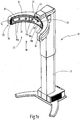
- the device 10 shown in the drawing is used to determine Zentrierparametern for spectacle fitting. It has a column 12 which carries a rigid camera support 14 which is height adjustable and in turn carries a number of cameras 16a, 16b.
- the camera carrier 14 is bent approximately circular in plan view and extends between two free ends 18, which are arranged at a distance to each other.
- an inner surface 20 of the camera carrier 14 encloses an interior space 22 in which the head of a subject is located when taking pictures by the cameras 16a, 16b.
- the inner surface 20 is concavely bent in a direction extending between the free ends 18 and has, for example, the shape of a portion of a cylindrical surface, wherein the cylinder may have a circular or oval base.
- a lifting device is arranged in the column 12, with which the camera support 14 can be moved up and down by a motor.
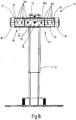
- All cameras 16a, 16b are arranged in a camera arrangement 26 extending between the free ends 18.
- the camera assembly 26 is formed as a camera row 26, the cameras 16a, 16b are all at the same height, with their optical axes are directed to the interior 22.
- the camera row 26 comprises a front camera 16a, which is arranged in the center of the camera carrier 14 and whose optical axis is frontal is directed to the face of the subject, as well as eight pairs symmetrically with respect to a running through the optical axis of the front camera 16a perpendicular plane of symmetry side cameras 16b of which four are directed from the left and right to the face of the subject.
- the cameras 16a, 16b are also calibrated so that they can simultaneously take calibrated images of the subject.
- the calibration includes the extrinsic properties such as the relative orientation of their optical axes and the relative arrangement of each other in space, as well as their intrinsic properties, ie the properties of the cameras themselves, which define, like a point in space, the internal coordinate system of the respective camera is located on the coordinates of the pixels of the recorded image is mapped.
- the camera support 14 encloses the interior 22 only forward, towards the column 12, and to the sides, so left and right of the head of the subject. Upwards, downwards and toward a rear side 30, it is open, the free ends 18 being at a distance of at least 25 cm from one another, so that the test person can easily approach from the rear side. In the illustrated embodiment, the distance is 70 to 80cm.
- a lighting device is provided with an upper light bar 32 extending above the camera row 26 and a lower light bar 34 extending below the camera row 26, which each have a multiplicity of LEDs as lighting means.
- the upper light bar 32 and the lower light bar 34 each extend continuously or intermittently over a length which is at least as long as the length of the circumferentially between the free ends 18 measured length of the camera row 26. This corresponds to a circumferential angle of at least 160 degrees , Near the free ends 18, the upper light bar 32 and the lower light bar 34 are each connected to each other by means of a vertically extending further light bar 36.
- the camera row 26 is thus completely framed by at least one row of LEDs.
- the device 10 also has a not-shown in the drawing control or regulating device, with the the light intensity emitted by the LEDs can be controlled or regulated as a function of the light intensity detected by the cameras 16a, 16b.
- the LEDs of the light strips 32, 34, 36 are combined into sectors whose radiated light intensities can be controlled or regulated separately from each other.
- the light intensities emitted by the individual LEDs can also be controlled or regulated separately from one another by means of the control or regulating device.
- the two side cameras 16b closest to the front camera 16a are set up to measure the distance of the subject's head from the center 38 of the camera carrier 14.
- the display unit has a plurality of differently colored light sources, which are arranged in a row.
- the middle light source glows green when the subject is correct. Starting from the middle light source, there is a yellow, an orange and a red light source in each direction in this order, which indicates the color according to the subject a little, clear or too far away from the center 38 of the camera support 14 or a little, clear, or too close to mid-38.
- a fixation device 42 arranged on the camera carrier 14 which generates a fixation pattern for the subject in the form of a speckle pattern.
- the fixation pattern is arranged slightly higher than the front camera 16a, so that the subject looks over them. So that his face can be taken up to the maximum extent.
- the device 10 is also particularly suitable for producing an avatar of the subject's head, which can be used to determine the centering parameters.
- a suitable process for geometric position determination such as triangulation
- a depth profile of the head is created, which approximates it very well.
- the head is represented by a multitude of points, which can be connected to each other by means of a net pattern or can be stored as a point cloud.
- the avatar determined in this way can be used to determine centering parameters which can not be determined or can only be approximately determined on the basis of the geometric properties of the spectacles or spectacle frame which the test person wears.
- a wide frame strap can obscure the eye in a side view to such an extent that the corneal vertex distance can not or only very inaccurately be determined.
- colored or highly specular lenses can not or only very poorly recognize the eyes.
- the depth profile of the avatar is projected onto the images taken by the cameras 16a, 16b of the subjects wearing the spectacles or spectacle frame, and the centering parameters, which can only be determined insufficiently due to the view restricted by the spectacles or spectacle frame, become determined by the image data of the avatar.
- the avatar can be adapted to the images of the subjects wearing the glasses or spectacle frame to minimize deviations.
- the apparatus 10 may be used to perform a computer-implemented method for determining centering parameters as follows.
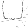
- the cameras 16a, 16b simultaneously provide calibrated images of the subject's head. From these images, geometrical position determination, in particular by means of triangulation, is used to determine geometric parameters which describe the position of the eyes. In particular, the avatar described above can also be used for this purpose. Then, a three-dimensional data record describing the geometrical parameters of the spectacle frame is provided, as in FIG. 2a illustrated by a spectacle frame 50.
- the spectacle frame 50 which is present as a three-dimensional point cloud, simplified with solid lines and not shown in the form of dots.
- FIG. 2b illustrates the rotation in the coordinate system of the cameras 16a, 16b, wherein the z-direction is given by the viewing direction of the front camera 16a.
- centering parameters are calculated, such as the corneal vertex distance.
- the glasses of the glasses are approximately represented by planes 52, as in FIG FIG. 3 shown, in which the spectacle frame 50 is also shown as a point cloud.
- the glass rims belonging to the spectacle frame are determined from the dataset describing the geometrical parameters of the spectacle frame, and a three-dimensional model for the spectacles of the spectacles is approximately adapted to the specific glass rims, this model consisting of the glass planes 52.
Landscapes
- Physics & Mathematics (AREA)
- Engineering & Computer Science (AREA)
- General Physics & Mathematics (AREA)
- Health & Medical Sciences (AREA)
- Computer Vision & Pattern Recognition (AREA)
- Geometry (AREA)
- Ophthalmology & Optometry (AREA)
- Optics & Photonics (AREA)
- Multimedia (AREA)
- Signal Processing (AREA)
- Theoretical Computer Science (AREA)
- Artificial Intelligence (AREA)
- Automation & Control Theory (AREA)
- Evolutionary Computation (AREA)
- Medical Informatics (AREA)
- Software Systems (AREA)
- Human Computer Interaction (AREA)
- Manufacturing & Machinery (AREA)
- Eyeglasses (AREA)
- Length Measuring Devices By Optical Means (AREA)
Priority Applications (5)
| Application Number | Priority Date | Filing Date | Title |
|---|---|---|---|
| EP17153560.2A EP3355103A1 (fr) | 2017-01-27 | 2017-01-27 | Procédé mis en uvre par ordinateur destiné à déterminer des paramètres de centrage |
| CN201880022350.4A CN110446968A (zh) | 2017-01-27 | 2018-01-24 | 用于确定定心参数的计算机实施的方法 |
| EP18702189.4A EP3574369A1 (fr) | 2017-01-27 | 2018-01-24 | Procédé mis en oeuvre par ordinateur pour déterminer des paramètres de centrage |
| PCT/EP2018/051751 WO2018138165A1 (fr) | 2017-01-27 | 2018-01-24 | Procédé mis en oeuvre par ordinateur pour déterminer des paramètres de centrage |
| US16/523,075 US11397339B2 (en) | 2017-01-27 | 2019-07-26 | Computer-implemented method for determining centring parameters |
Applications Claiming Priority (1)
| Application Number | Priority Date | Filing Date | Title |
|---|---|---|---|
| EP17153560.2A EP3355103A1 (fr) | 2017-01-27 | 2017-01-27 | Procédé mis en uvre par ordinateur destiné à déterminer des paramètres de centrage |
Publications (1)
| Publication Number | Publication Date |
|---|---|
| EP3355103A1 true EP3355103A1 (fr) | 2018-08-01 |
Family
ID=57909542
Family Applications (2)
| Application Number | Title | Priority Date | Filing Date |
|---|---|---|---|
| EP17153560.2A Withdrawn EP3355103A1 (fr) | 2017-01-27 | 2017-01-27 | Procédé mis en uvre par ordinateur destiné à déterminer des paramètres de centrage |
| EP18702189.4A Pending EP3574369A1 (fr) | 2017-01-27 | 2018-01-24 | Procédé mis en oeuvre par ordinateur pour déterminer des paramètres de centrage |
Family Applications After (1)
| Application Number | Title | Priority Date | Filing Date |
|---|---|---|---|
| EP18702189.4A Pending EP3574369A1 (fr) | 2017-01-27 | 2018-01-24 | Procédé mis en oeuvre par ordinateur pour déterminer des paramètres de centrage |
Country Status (4)
| Country | Link |
|---|---|
| US (1) | US11397339B2 (fr) |
| EP (2) | EP3355103A1 (fr) |
| CN (1) | CN110446968A (fr) |
| WO (1) | WO2018138165A1 (fr) |
Cited By (1)
| Publication number | Priority date | Publication date | Assignee | Title |
|---|---|---|---|---|
| US11215845B2 (en) | 2017-06-01 | 2022-01-04 | Carl Zeiss Vision International Gmbh | Method, device, and computer program for virtually adjusting a spectacle frame |
Families Citing this family (1)
| Publication number | Priority date | Publication date | Assignee | Title |
|---|---|---|---|---|
| EP4227732A1 (fr) | 2022-02-14 | 2023-08-16 | Carl Zeiss Vision International GmbH | Procédé d'enregistrement d'image de tête et dispositif mobile correspondant |
Citations (4)
| Publication number | Priority date | Publication date | Assignee | Title |
|---|---|---|---|---|
| US20030081173A1 (en) * | 2001-10-25 | 2003-05-01 | Dreher Andreas W. | Custom eyeglass manufacturing method |
| US6792401B1 (en) * | 2000-10-31 | 2004-09-14 | Diamond Visionics Company | Internet-based modeling kiosk and method for fitting and selling prescription eyeglasses |
| FR2987908A1 (fr) * | 2012-03-12 | 2013-09-13 | Digiteyezer | Scanner automatique et procede de numerisation 3d d'une portion peripherique cephalique humaine |
| US20150055085A1 (en) * | 2013-08-22 | 2015-02-26 | Bespoke, Inc. | Method and system to create products |
Family Cites Families (1)
| Publication number | Priority date | Publication date | Assignee | Title |
|---|---|---|---|---|
| US20130088490A1 (en) | 2011-04-04 | 2013-04-11 | Aaron Rasmussen | Method for eyewear fitting, recommendation, and customization using collision detection |
-
2017
- 2017-01-27 EP EP17153560.2A patent/EP3355103A1/fr not_active Withdrawn
-
2018
- 2018-01-24 EP EP18702189.4A patent/EP3574369A1/fr active Pending
- 2018-01-24 WO PCT/EP2018/051751 patent/WO2018138165A1/fr unknown
- 2018-01-24 CN CN201880022350.4A patent/CN110446968A/zh active Pending
-
2019
- 2019-07-26 US US16/523,075 patent/US11397339B2/en active Active
Patent Citations (4)
| Publication number | Priority date | Publication date | Assignee | Title |
|---|---|---|---|---|
| US6792401B1 (en) * | 2000-10-31 | 2004-09-14 | Diamond Visionics Company | Internet-based modeling kiosk and method for fitting and selling prescription eyeglasses |
| US20030081173A1 (en) * | 2001-10-25 | 2003-05-01 | Dreher Andreas W. | Custom eyeglass manufacturing method |
| FR2987908A1 (fr) * | 2012-03-12 | 2013-09-13 | Digiteyezer | Scanner automatique et procede de numerisation 3d d'une portion peripherique cephalique humaine |
| US20150055085A1 (en) * | 2013-08-22 | 2015-02-26 | Bespoke, Inc. | Method and system to create products |
Cited By (2)
| Publication number | Priority date | Publication date | Assignee | Title |
|---|---|---|---|---|
| US11215845B2 (en) | 2017-06-01 | 2022-01-04 | Carl Zeiss Vision International Gmbh | Method, device, and computer program for virtually adjusting a spectacle frame |
| US11262597B2 (en) | 2017-06-01 | 2022-03-01 | Carl Zeiss Vision International Gmbh | Method, device, and computer program for virtually adjusting a spectacle frame |
Also Published As
| Publication number | Publication date |
|---|---|
| US20200057316A1 (en) | 2020-02-20 |
| US11397339B2 (en) | 2022-07-26 |
| EP3574369A1 (fr) | 2019-12-04 |
| WO2018138165A1 (fr) | 2018-08-02 |
| CN110446968A (zh) | 2019-11-12 |
Similar Documents
| Publication | Publication Date | Title |
|---|---|---|
| EP3574371B1 (fr) | Procédé mis en oeuvre par ordinateur destiné à déterminer des paramètres de centrage | |
| EP3588175B1 (fr) | Dispositif de détermination des paramètres de centrage pour l'adaptation de lunettes | |
| EP3354190B1 (fr) | Procédé mis en uvre par ordinateur destiné à la détection d'un sommet de la cornée | |
| EP3183616B1 (fr) | Détermination de données d'utilisateur avec prise en compte de données d'image d'une monture de lunettes choisie | |
| EP3210071B1 (fr) | Dispositif et procédé de détermination de paramètres optiques | |
| EP3256036B1 (fr) | Dispositif et procédé de détermination de distance et/ou de centrage à l'aide des réflexions cornéennes | |
| EP2282232A1 (fr) | Dispositif et procédé pour déterminer des paramètres optiques d'un utilisateur, et produit de programme informatique | |
| DE102006033491A1 (de) | Vorrichtung und Verfahren zum Bestimmen einer Trageposition einer Brille, Computerprogrammvorrichtung | |
| EP3413122B1 (fr) | Procédé, dispositif et programme informatique destinés à déterminer un point de vue proche | |
| EP3574370B1 (fr) | Procédé assisté par ordinateur destiné à déterminer une représentation d'un bord de monture de lunette ou d'une représentation des bords de verres de lunettes | |
| DE102011115239A1 (de) | Bestimmung der Scheibenform unter Berücksichtigung von Tracerdaten | |
| EP3497509A1 (fr) | Procédé et dispositif de vérification du centrage d'au moins un verre de lunettes | |
| DE102013010684B4 (de) | Ein Verfahren und eine Messvorrichtung zur verbesserten Erfassung von Fassungsparametern einer Brillenfassung sowie Stützscheibe | |
| EP3355103A1 (fr) | Procédé mis en uvre par ordinateur destiné à déterminer des paramètres de centrage | |
| EP2228585A2 (fr) | Unité de réception pour un système de centrage vidéo |
Legal Events
| Date | Code | Title | Description |
|---|---|---|---|
| PUAI | Public reference made under article 153(3) epc to a published international application that has entered the european phase |
Free format text: ORIGINAL CODE: 0009012 |
|
| AK | Designated contracting states |
Kind code of ref document: A1 Designated state(s): AL AT BE BG CH CY CZ DE DK EE ES FI FR GB GR HR HU IE IS IT LI LT LU LV MC MK MT NL NO PL PT RO RS SE SI SK SM TR |
|
| AX | Request for extension of the european patent |
Extension state: BA ME |
|
| STAA | Information on the status of an ep patent application or granted ep patent |
Free format text: STATUS: THE APPLICATION IS DEEMED TO BE WITHDRAWN |
|
| 18D | Application deemed to be withdrawn |
Effective date: 20190202 |