EP3354990A1 - Bedienelement für ein haushaltsgerät mit einem 2k-kunststoffgehäuse oder einem 1k-kunststoffgehäuse sowie bedienvorrichtung und haushaltsgerät - Google Patents
Bedienelement für ein haushaltsgerät mit einem 2k-kunststoffgehäuse oder einem 1k-kunststoffgehäuse sowie bedienvorrichtung und haushaltsgerät Download PDFInfo
- Publication number
- EP3354990A1 EP3354990A1 EP18151410.0A EP18151410A EP3354990A1 EP 3354990 A1 EP3354990 A1 EP 3354990A1 EP 18151410 A EP18151410 A EP 18151410A EP 3354990 A1 EP3354990 A1 EP 3354990A1
- Authority
- EP
- European Patent Office
- Prior art keywords
- housing
- operating
- control
- operating device
- plastic
- Prior art date
- Legal status (The legal status is an assumption and is not a legal conclusion. Google has not performed a legal analysis and makes no representation as to the accuracy of the status listed.)
- Granted
Links
Images


Classifications
-
- F—MECHANICAL ENGINEERING; LIGHTING; HEATING; WEAPONS; BLASTING
- F24—HEATING; RANGES; VENTILATING
- F24C—DOMESTIC STOVES OR RANGES ; DETAILS OF DOMESTIC STOVES OR RANGES, OF GENERAL APPLICATION
- F24C7/00—Stoves or ranges heated by electric energy
- F24C7/08—Arrangement or mounting of control or safety devices
- F24C7/082—Arrangement or mounting of control or safety devices on ranges, e.g. control panels, illumination
- F24C7/086—Arrangement or mounting of control or safety devices on ranges, e.g. control panels, illumination touch control
-
- H—ELECTRICITY
- H03—ELECTRONIC CIRCUITRY
- H03K—PULSE TECHNIQUE
- H03K17/00—Electronic switching or gating, i.e. not by contact-making and –breaking
- H03K17/94—Electronic switching or gating, i.e. not by contact-making and –breaking characterised by the way in which the control signals are generated
- H03K17/96—Touch switches
- H03K17/962—Capacitive touch switches
- H03K17/9622—Capacitive touch switches using a plurality of detectors, e.g. keyboard
-
- H—ELECTRICITY
- H03—ELECTRONIC CIRCUITRY
- H03K—PULSE TECHNIQUE
- H03K2217/00—Indexing scheme related to electronic switching or gating, i.e. not by contact-making or -breaking covered by H03K17/00
- H03K2217/94—Indexing scheme related to electronic switching or gating, i.e. not by contact-making or -breaking covered by H03K17/00 characterised by the way in which the control signal is generated
- H03K2217/96—Touch switches
- H03K2217/96015—Constructional details for touch switches
- H03K2217/96023—Details of electro-mechanic connections between different elements, e.g.: sensing plate and integrated circuit containing electronics
-
- H—ELECTRICITY
- H03—ELECTRONIC CIRCUITRY
- H03K—PULSE TECHNIQUE
- H03K2217/00—Indexing scheme related to electronic switching or gating, i.e. not by contact-making or -breaking covered by H03K17/00
- H03K2217/94—Indexing scheme related to electronic switching or gating, i.e. not by contact-making or -breaking covered by H03K17/00 characterised by the way in which the control signal is generated
- H03K2217/96—Touch switches
- H03K2217/9607—Capacitive touch switches
- H03K2217/960755—Constructional details of capacitive touch and proximity switches
-
- H—ELECTRICITY
- H03—ELECTRONIC CIRCUITRY
- H03K—PULSE TECHNIQUE
- H03K2217/00—Indexing scheme related to electronic switching or gating, i.e. not by contact-making or -breaking covered by H03K17/00
- H03K2217/94—Indexing scheme related to electronic switching or gating, i.e. not by contact-making or -breaking covered by H03K17/00 characterised by the way in which the control signal is generated
- H03K2217/96—Touch switches
- H03K2217/9607—Capacitive touch switches
- H03K2217/960785—Capacitive touch switches with illumination
Definitions
- the invention relates to an operating element for a household appliance.
- the operating element has a capacitive sensor key.
- This capacitive sensor key has a housing, which is at least partially formed of an electrically conductive plastic.
- the invention also relates to an operating device with such a control element as well as a household appliance.
- Capacitive sensor keys are known in the art. For example, the DE 10 2012 010 321 A1 such.
- the local capacitive sensor button is part of an operating device of a hob.
- the capacitive sensor key with its housing is formed there in particular as a 3K injection component.
- One aspect of the invention relates to an operating element for a household appliance, wherein the operating element is designed as a capacitive sensor button.
- This capacitive sensor key has a housing, which is at least partially formed of an electrically conductive plastic.
- the housing is designed as a 2K plastic housing or as a 1K plastic housing. This means that the housing is designed as a spray component and is injected at most from two different plastics.
- a Such a configuration simplifies the manufacturability of this operating element and nevertheless maintains the capacitive active function unrestricted. By such a configuration of a control element, the production can therefore also be faster and, moreover, the operating element is also more cost-effective.
- the housing is not elastic.
- the housing has contact pins, which are designed for passage in plated-through holes in a printed circuit board, wherein these contact pins are formed from the electrically conductive plastic.
- the mechanically stable attachment to the printed circuit board on the one hand and the electrical connection on the other hand is then realized in a multifunctional manner.
- the housing has a control housing area for operation with a finger, and has a representational own display housing area for optically displaying light information, wherein the control housing area and the display housing area are integrally formed or manufactured.
- this embodiment also realizes two other objectively different and thus separated large areas of the one-piece housing, which are assigned different functions.
- the housing is touched, the display of the optical light information then generated at the same time is not covered, as is the case in embodiments in which the operating housing area and the display housing area are the same areas.
- the individual housing areas can then also be manufactured individually, in particular with regard to their wall thicknesses.
- the display housing area can then be formed, for example, with thinner walls and / or smaller. As a result, material can be saved, whereby a weight reduction is achieved.
- the operating housing area and the display housing area are formed adjacent to one another and directly adjacent to one another. As a result of this embodiment which does not overlap, the abovementioned advantages are again improved and nevertheless a compact housing is created.
- a certain mechanical stabilization of the individual housing portions is mutually achieved by this configuration.
- a housing wall is part of the operating housing area and the display housing area and these housing areas are spatially separated from each other by this housing wall.
- each enclosed by the housing areas volume are therefore separated from each other and by this one housing wall is assigned functionally two housing areas, material can be saved here again.
- the housing wall of the housing separating the operating housing area and the display housing area is arranged in a seated manner on the printed circuit board, the printed circuit board being part of the operating device.
- the housing is partially formed of the electrically conductive plastic and partially made of an electrically non-conductive plastic.
- An electrical conductivity which is achieved for example by adding graphite particles or soot particles or metal powder, is therefore only locally formed here.
- the control element can be designed without illumination or light symbols and thus be designed only as regards the electrical functionality as a capacitive sensor key.
- At least one light source may also be assigned to this operating element, with which optical displays, in particular also light information, can take place, which represent, for example, an operating setting which is accompanied by touching the capacitive sensor key.
- the invention also relates to an operating device for a household appliance, which has a control element according to the above-mentioned aspect or an advantageous embodiment thereof.
- the invention also relates to a household appliance, in particular a cooking appliance, which has a corresponding operating device.
- the cooking appliance may for example be a hob.
- the housing of the capacitive sensor key can be formed geometrically diverse. Both in the geometry and thus the specific shape as well as in the dimensions, and thus the height, the width and the depth, a wide variety of specifications can be realized.
- the housing may be quadrangular or pentagonal, hexagonal or beyond an even higher number of corners have. It may be closed on the side facing away from the circuit board or may be open. In the closed state, a ceiling wall is thus formed, which can be completely closed.
- the top wall can also have locally individual perforations, which in turn can have individual shapes, for example a corner-free contour or even an angular contour. It is also possible that this ceiling wall is very filigree and, for example, designed only as a circumferential frame. This frame can then be formed square, pentagonal, hexagonal or beyond with even more corners. Likewise, a corner-free form, such as a circle or an oval is also possible here.
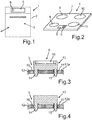
- Fig. 1 is shown in a simplified front view of a household appliance 1, which is designed as a cooking appliance, for example, is designed as a baking oven.
- This household appliance 1 has a housing in which a cooking chamber 3 is formed, which is bounded by walls of a muffle. Front side of the cooking chamber 3 is closed by a door 4, which is shown here in the closed state.
- the household appliance 1 also has an operating device 5, which has at least one operating element 6, which is designed as a capacitive sensor button.
- a further embodiment of a household appliance 1 is shown, which is designed as a cooking appliance and is designed here as a hob.
- This household appliance 1 according to Fig. 2 has a cooktop plate 7, on the number and size of only exemplary and not conclusive to understand several cooking zones 8, 9, 10 and 11 are formed.
- This household appliance 1 also has an operating device 5, which likewise has at least one operating element 6, which is a capacitive sensor button.
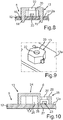
- FIG. 3 is an embodiment of an operating device 5 is shown in a vertical sectional view, in which case partial elements are shown.
- the operating device 5 has a printed circuit board 12 on which the operating element 6 is arranged in the form of the capacitive sensor key.
- This capacitive sensor button has a housing 13, which is formed in the embodiment shown as 1K plastic housing.
- This housing 13 also has contact pins 14 and 15 in an integral configuration, which are inserted through plated-through holes 16 and 17 of the printed circuit board 12 and are electrically connected to corresponding electrical leads.
- the housing 13 is formed of an electrically conductive plastic and rigid in itself, so that the housing 13 is not elastic.
- the control element 6 shown here in the form of the capacitive sensor key is formed without illumination and thus also without light symbols.
- FIG. 4 a further embodiment of an operating device 5 is shown in a corresponding vertical sectional view.
- the housing 13 In contrast to the representation according to Fig. 3 is the housing 13 not with an upwardly open trough 18th trained as they are in Fig. 3 is shown, but formed in this regard closed solid block.
- FIG. 5a, 5b, 5c and 5d perspective views of possible embodiments of the housing 13 are shown.
- Fig. 5a an embodiment of a 1K plastic housing is shown, which on the circuit board 12 facing away from the upper end has a peripheral frame 19 which is formed here quadrangular.
- a frame 19 is formed, which is, however, designed hexagonal here.
- Fig. 5c is a perspective view of a housing 13, as shown in FIG Fig. 4 is trained.
- the housing 13 is completely closed at its upper end facing away from the printed circuit board 12 and designed plate-like, so that here is a closed ceiling wall 20, which is preferably formed here quadrangular realized.
- Fig. 5d an alternative embodiment is shown, in which the ceiling wall 20 is formed rounded at the corners.
- Fig. 6 is a further embodiment of an operating device 5 is shown in a further vertical sectional view, in which case also in this embodiment, the housing 13 is formed as a 1K plastic housing.
- the one-piece housing 13 is not formed here as a solid block, which sits with a central area over the entire surface on the top 12a of the circuit board 12, but it sits here only the edge. Through the housing 13 and the top 12a, a volume space 21 is then limited.
- the housing 13 is thus formed as a cover and thus as a hollow body.
- Fig. 7a is shown in a perspective view of a possible shape design of the housing 13.
- a square shape realized is that as shown in Fig. 7b this case 13, as it is in Fig. 6 is shown in section, is hexagonal.
- the comments according to Fig. 4 to Fig. 7b show capacitive sensor buttons that are designed without illumination and thus without light symbols.
- the operating element 6 and thus the capacitive sensor key has a lighting and thus at least also comprises a light source.
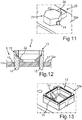
- FIG. 8 in a sectional view, another embodiment of an operating device 5 is shown.
- This embodiment is in particular geometrically according to the embodiment Fig. 6 adapted, in contrast, on a ceiling wall 20, an opening 22 is formed through which light of a arranged on the circuit board 12 light source 23 can escape.
- Fig. 9 is a perspective view of the embodiment according to Fig. 8 shown.
- the housing 13 according to the embodiment in FIG Fig. 7b realized and in the top wall 20 to recognize the opening 22.
- the housing 13 may also, for example, according to the embodiment in Fig. 7a be realized and there in the ceiling wall 20 a corresponding opening 22 may be formed.
- FIG. 10 A particularly advantageous embodiment is in Fig. 10 shown, wherein also a vertical sectional view is shown here. Also in this embodiment, the operating element 6 is formed with a lighting or luminous symbols.
- the operating element 6 has a housing 13, which has a control housing area 24 and additionally a display housing area 25.
- the housing 13 is integrally formed and may preferably be formed as a 1K plastic housing. It can be seen that the two housing areas 24 and 25 are viewed in the horizontal direction next to each other and each designed as a hood-like components, so that below volume 26 and 27 are formed.
- the housing 13 has a housing wall 28, which is both a component of the operating housing area 24 and of the display housing area 25. This housing wall 28 separates the volumes 26 and 27. In particular, this housing wall 28 sitting on the top 12a of the circuit board 12.
- the housing areas 24 and 25 are arranged without overlapping to each other and directly adjacent to each other, wherein they share in particular the housing wall 28.
- the display housing area 25 in the vertical direction and thus seen in the height direction is lower than the operating housing area 24. Also in the horizontal extent, this display housing area 25 is shorter or smaller than the operating housing area 24.
- a ceiling wall 29 of the display housing portion 25 is an opening 30 is formed, through which the light of the at least one light source 23 can pass.
- the opening 22 may also preferably be closed by a light-transmitting element. Likewise, this may also be the embodiments according to FIGS. 8 and 9 be realized.
- the housing 13 is formed as a 1K plastic housing and thus formed from an electrically conductive plastic.
- Fig. 11 is an embodiment of the housing 13 is shown in a perspective view, in which case the operating housing portion 24 is formed hexagonal and the display housing portion 25 is formed quadrangular. However, this is only to be understood as an exemplary embodiment.
- this operating device 5 is below the hob plate 7 in the execution of the household appliance 1 as a hob, as it is in Fig. 2 is shown arranged.
- the control housing portion 24 can then be marked on the top of the hob plate 7 by a print, so that a user then knows exactly at what point on the top of the hob plate 2 he has to squeeze or make a touch to operate the capacitive sensor key.
- a further embodiment of an operating device 5 is shown in a vertical sectional view.
- the housing 13 of the control element 6 is formed as a 2K plastic housing.
- An outer housing region 31 is formed here from an electrically conductive plastic and an insert or an inner housing region 32 is formed from a non-electrically conductive plastic.
- the inner housing portion 32 is, as it is in Fig. 12 is shown, at least partially funnel-shaped and extends only partially over the height of the outer housing portion 31.
- a Fig. 13 is shown in a perspective view in an exemplary quadrangular geometry of the housing 13, this control element 6 without illumination and thus formed without light symbols.
- the capacitive sensor button is formed with a lighting
- the operating device 5 has an operating element 6, as explained above, and additionally has a further operating element, which has a capacitive sensor button, which has a 3K plastic housing.
- Another advantage of the embodiment as a maximum 2K plastic housing is also to be seen in that many smaller structures of the electrically conductive components can be performed, which brings functional advantages.
Landscapes
- Engineering & Computer Science (AREA)
- Chemical & Material Sciences (AREA)
- Combustion & Propulsion (AREA)
- Mechanical Engineering (AREA)
- General Engineering & Computer Science (AREA)
- Push-Button Switches (AREA)
- Switches That Are Operated By Magnetic Or Electric Fields (AREA)
Abstract
Description
- Die Erfindung betrifft ein Bedienelement für ein Haushaltsgerät. Das Bedienelement weist eine kapazitive Sensortaste auf. Diese kapazitive Sensortaste weist ein Gehäuse auf, das zumindest bereichsweise aus einem elektrisch leitfähigen Kunststoff ausgebildet ist. Des Weiteren betrifft die Erfindung auch eine Bedienvorrichtung mit einem derartigen Bedienelement als auch ein Haushaltsgerät.
- Kapazitive Sensortasten sind aus dem Stand der Technik bekannt. Beispielsweise offenbart die
DE 10 2012 010 321 A1 eine derartige. Die dortige kapazitive Sensortaste ist Bestandteil einer Bedieneinrichtung eines Kochfelds. Die kapazitive Sensortaste mit ihrem Gehäuse ist dort insbesondere als 3K-Spritzbauteil ausgebildet. - Derartige Bedienelemente sind in der Herstellung sehr aufwendig und auch bei komplexeren Formgebungen des Gehäuses ist die Ausgestaltung der jeweiligen Teilbereiche der verschiedenen Kunststoffe dieses 3K-Spritzbauteils schwierig.
- Es ist Aufgabe der vorliegenden Erfindung, ein Bedienelement als kapazitive Sensortaste zu schaffen, bei welchem das Gehäuse einfacher herstellbar ist und dennoch bezüglich der kapazitiven Funktionalität uneingeschränkt wirkend ist.
- Diese Aufgabe wird durch ein Bedienelement, eine Bedienvorrichtung und ein Haushaltsgerät gemäß den unabhängigen Ansprüchen gelöst.
- Ein Aspekt der Erfindung betrifft ein Bedienelement für ein Haushaltsgerät, wobei das Bedienelement als kapazitive Sensortaste ausgebildet ist. Diese kapazitive Sensortaste weist ein Gehäuse auf, das zumindest bereichsweise aus einem elektrisch leitfähigen Kunststoff ausgebildet ist. Das Gehäuse ist als 2K-Kunststoffgehäuse oder als 1K-Kunststoffgehäuse ausgebildet. Dies bedeutet, dass das Gehäuse als Spritzbauteil ausgebildet ist und maximal aus zwei verschiedenen Kunststoffen gespritzt ist. Eine derartige Ausgestaltung ist die Herstellbarkeit dieses Bedienelements vereinfacht und dennoch die kapazitive Wirkfunktion uneingeschränkt aufrechterhalten. Durch eine derartige Ausgestaltung eines Bedienelements kann somit die Fertigung auch schneller erfolgen und darüber hinaus ist das Bedienelement dann auch kostengünstiger.
- Vorzugsweise ist vorgesehen, dass das Gehäuse nicht elastisch ausgebildet ist. Durch eine derartige Ausgestaltung ist dann auch die positionsgenaue Montage auf einer Leiterplatte einer Bedienvorrichtung einfach ermöglicht.
- Vorzugsweise weist das Gehäuse Kontaktstifte auf, die zum Hindurchführen in Durchkontaktierungen in einer Leiterplatte ausgebildet sind, wobei diese Kontaktstifte aus dem elektrisch leitfähigen Kunststoff ausgebildet sind. Für eine derartige Ausgestaltung wird dann in multifunktioneller Weise die mechanisch stabile Befestigung an der Leiterplatte einerseits und die elektrische Verbindung andererseits realisiert.
- Vorzugsweise ist vorgesehen, dass das Gehäuse einen Bediengehäusebereich zum Bedienen mit einem Finger aufweist, und einen gegenständlich eigenen Anzeigegehäusebereich zum optischen Anzeigen von Lichtinformationen aufweist, wobei der Bediengehäusebereich und der Anzeigegehäusebereich einstückig ausgebildet sind beziehungsweise hergestellt sind. Durch diese Ausgestaltung sind somit zwei auch gegenständlich andere und somit separierte große Bereiche des einstückigen Gehäuses realisiert, denen unterschiedliche Funktionen zugeordnet sind. Durch diese Ausgestaltung wird bei einem Berühren des Gehäuses die dann zugleich erzeugte Anzeige der optischen Lichtinformation nicht verdeckt, wie es bei Ausführungen der Fall ist, bei denen der Bediengehäusebereich und der Anzeigegehäusebereich die gleichen Bereiche sind.
- Durch diese Ausgestaltung lässt sich ein zuverlässiges Betätigen und gleichzeitiges Wahrnehmen von Lichtinformationen realisieren. Darüber hinaus können die einzelnen Gehäusebereiche dann auch individuell gefertigt werden, insbesondere im Hinblick auf ihre Wanddicken. Insbesondere der Anzeigegehäusebereich kann dann beispielsweise auch mit dünneren Wänden und/oder kleiner ausgebildet werden. Dadurch kann auch Material eingespart werden, wodurch auch eine Gewichtsreduzierung erzielt ist. Vorzugsweise ist vorgesehen, dass der Bediengehäusebereich und der Anzeigegehäusebereich nebeneinander und direkt aneinander angrenzend ausgebildet sind. Durch diese überlappungsfreie Ausgestaltung werden die oben genannten Vorteile nochmals verbessert und dennoch ein kompaktes Gehäuse geschaffen. Darüber hinaus ist durch diese Ausgestaltung auch eine gewisse mechanische Stabilisierung der einzelnen Gehäusebereiche gegenseitig erreicht.
- Vorzugsweise ist vorgesehen, dass eine Gehäusewand Bestandteil des Bediengehäusebereichs und des Anzeigegehäusebereichs ist und diese Gehäusebereiche durch diese Gehäusewand voneinander räumlich getrennt sind. Insbesondere die jeweils durch die Gehäusebereiche umschlossenen Volumen sind somit getrennt voneinander und indem diese eine Gehäusewand funktionell beiden Gehäusebereichen zugeordnet ist, kann auch hier wiederum Material eingespart werden.
- Vorzugsweise ist die den Bediengehäusebereich und den Anzeigegehäusebereich trennende Gehäusewand des Gehäuses auf der Leiterplatte aufsitzend angeordnet, wobei die Leiterplatte Bestandteil der Bedienvorrichtung ist.
- Insbesondere ist vorgesehen, dass bei einer Ausgestaltung als 2K-Kunststoffhäuse das Gehäuse bereichsweise aus dem elektrisch leitfähigen Kunststoff und bereichsweise aus einem elektrisch nicht leitfähigen Kunststoff ausgebildet ist. Eine elektrische Leitfähigkeit, die beispielsweise durch Zugabe von Graphitpartikeln oder Rußpartikeln oder Metallpulver erreicht ist, ist somit hier nur lokal ausgebildet.
- Das Bedienelement kann ohne Beleuchtung beziehungsweise Leuchtsymbole ausgebildet sein und somit lediglich nur bezüglich der elektrischen Funktionalität als kapazitive Sensortaste ausgebildet sein.
- Bei einer alternativen Ausgestaltung kann jedoch auch zumindest eine Lichtquelle diesem Bedienelement zugeordnet sein, mit welcher dann optische Anzeigen, insbesondere auch Lichtinformationen erfolgen können, die beispielsweise eine Bedieneinstellung, die durch Berühren der kapazitiven Sensortaste einhergeht, darstellen.
- Des Weiteren betrifft die Erfindung auch eine Bedienvorrichtung für ein Haushaltsgerät, welches ein Bedienelement gemäß dem oben genannten Aspekt oder einer vorteilhaften Ausgestaltung davon aufweist.
- Des Weiteren betrifft die Erfindung auch ein Haushaltsgerät, insbesondere ein Gargerät, welches eine entsprechende Bedienvorrichtung aufweist. Das Gargerät kann beispielsweise ein Kochfeld sein.
- Das Gehäuse der kapazitiven Sensortaste kann geometrisch vielfältigst ausgebildet sein. Sowohl in der Geometrie und somit der spezifischen Formgebung als auch bezüglich der Ausmaße, und somit der Höhe, der Breite und der Tiefe, können unterschiedlichste Spezifikationen realisiert sein. Das Gehäuse kann viereckig sein oder auch fünfeckig, sechseckig oder darüber hinausgehend eine noch höhere Eckenzahl aufweisen. Es kann an der der Leiterplatte abgewandten Oberseite geschlossen sein oder auch geöffnet sein. In geschlossenem Zustand ist somit eine Deckenwand ausgebildet, die vollkommen geschlossen sein kann. Die Deckenwand kann andererseits jedoch auch lokal individuelle Durchbrechungen aufweisen, die wiederum individuelle Formgebungen, beispielsweise eine eckenfreie Kontur oder aber auch eine eckige Kontur, aufweisen können. Ebenso ist es möglich, dass diese Deckenwand sehr filigran ausgebildet ist und beispielsweise nur als umlaufender Rahmen gestaltet ist. Auch dieser Rahmen kann dann viereckig, fünfeckig, sechseckig oder darüber hinausgehend mit noch mehreren Ecken ausgebildet sein. Ebenso ist auch hier eine eckenfreie Form, beispielsweise ein Kreis oder ein Oval möglich.
- Ein Ausführungsbeispiel der Erfindung wird nachfolgend anhand schematischer Zeichnungen näher erläutert. Es zeigen:
- Fig. 1
- eine vereinfachte Frontansicht eines Ausführungsbeispiels eines erfindungsgemäßen Haushaltsgeräts;
- Fig. 2
- eine perspektivische Darstellung eines weiteren Ausführungsbeispiels eines erfindungsgemäßen Haushaltsgeräts;
- Fig. 3
- eine Schnittdarstellung durch ein Ausführungsbeispiel einer erfindungsgemäßen Bedienvorrichtung;
- Fig. 4
- eine Schnittdarstellung durch ein weiteres Ausführungsbeispiel einer erfindungsgemäßen Bedienvorrichtung;
- Fig. 5a bis 5d
- perspektivische Darstellungen von verschiedenen Ausführungsbeispielen von Gehäusen eines Ausführungsbeispiels eines Bedienelements, wie es bei einer Bedienvorrichtung für ein Haushaltsgerät verbaut sein kann;
- Fig. 6
- eine Schnittdarstellung eines weiteren Ausführungsbeispiels einer erfindungsgemäßen Bedienvorrichtung;
- Fig. 7a und 7b
- perspektive Darstellungen zu der Bedienvorrichtung gemäß
Fig. 6 ; - Fig. 8
- eine Schnittdarstellung für ein weiteres Ausführungsbeispiel einer erfindungsgemäßen Bedienvorrichtung;
- Fig. 9
- eine perspektivische Darstellung des Ausführungsbeispiels der Bedienvorrichtung gemäß
Fig. 8 ; - Fig. 10
- eine weitere Schnittdarstellung durch ein weiteres Ausführungsbeispiel einer erfindungsgemäßen Bedienvorrichtung;
- Fig. 11
- eine perspektivische Darstellung eines Ausführungsbeispiels der Bedienvorrichtung gemäß
Fig. 10 ; - Fig. 12
- eine weitere Schnittdarstellung durch ein weiteres Ausführungsbeispiel einer erfindungsgemäßen Bedienvorrichtung; und
- Fig. 13
- eine perspektivische Darstellung der Bedienvorrichtung gemäß
Fig. 12 . - In den Figuren werden gleiche oder funktionsgleiche Elemente mit den gleichen Bezugszeichen versehen.
- In
Fig. 1 ist in einer vereinfachten Frontansicht ein Haushaltsgerät 1 gezeigt, welches als Gargerät ausgebildet ist, beispielsweise als Backofen ausgebildet ist. Dieses Haushaltsgerät 1 weist ein Gehäuse auf, in dem ein Garraum 3 ausgebildet ist, der durch Wände einer Muffel begrenzt ist. Frontseitig ist der Garraum 3 durch eine Tür 4 verschließbar, die hier in geschlossenem Zustand gezeigt ist. Das Haushaltsgerät 1 weist darüber hinaus eine Bedienvorrichtung 5 auf, die zumindest ein Bedienelement 6 aufweist, welches als kapazitive Sensortaste ausgebildet ist. - In
Fig. 2 ist ein weiteres Ausführungsbeispiel eines Haushaltsgeräts 1 gezeigt, welches als Gargerät ausgebildet ist und hier als Kochfeld ausgebildet ist. Dieses Haushaltsgerät 1 gemäßFig. 2 weist eine Kochfeldplatte 7 auf, auf der in Anzahl und Größe lediglich beispielhaft und nicht abschließend zu verstehen mehrere Kochzonen 8, 9, 10 und 11 ausgebildet sind. Dieses Haushaltsgerät 1 weist ebenfalls eine Bedienvorrichtung 5 auf, welche ebenfalls zumindest ein Bedienelement 6 aufweist, das eine kapazitive Sensortaste ist. - In
Fig. 3 ist in einer Vertikalschnittdarstellung ein Ausführungsbeispiel einer Bedienvorrichtung 5 gezeigt, wobei hier Teilelemente dargestellt sind. Die Bedienvorrichtung 5 weist eine Leiterplatte 12 auf, auf welcher das Bedienelement 6 in Form der kapazitiven Sensortaste angeordnet ist. Diese kapazitive Sensortaste weist ein Gehäuse 13 auf, welches in der gezeigten Ausführung als 1K-Kunststoffgehäuse ausgebildet ist. Dieses Gehäuse 13 weist in einer einstückigen Ausgestaltung auch Kontaktstifte 14 und 15 auf, welche durch Durchkontaktierungen 16 und 17 der Leiterplatte 12 hindurchgesteckt sind und mit entsprechenden elektrischen Leitungen elektrisch verbunden sind. Das Gehäuse 13 ist aus einem elektrisch leitfähigen Kunststoff ausgebildet und in sich starr, sodass das Gehäuse 13 nicht elastisch ausgebildet ist. Das hier gezeigte Bedienelement 6 in Form der kapazitiven Sensortaste ist ohne Beleuchtung und somit auch ohne Leuchtsymbole ausgebildet. - In
Fig. 4 ist in einer entsprechenden Vertikalschnittdarstellung ein weiteres Ausführungsbeispiel einer Bedienvorrichtung 5 gezeigt. Im Unterschied zur Darstellung gemäßFig. 3 ist das Gehäuse 13 nicht mit einer nach obenhin offenen Mulde 18 ausgebildet, wie sie inFig. 3 gezeigt ist, sondern als diesbezüglich geschlossener massiver Block ausgebildet. - In
Fig. 5a, 5b, 5c und 5d sind perspektivische Darstellungen von möglichen Ausgestaltungen des Gehäuses 13 gezeigt. InFig. 5a ist eine Ausführungsform eines 1K-Kunststoffgehäuses gezeigt, welches auf dem der Leiterplatte 12 abgewandten oberen Ende einen umlaufenden Rahmen 19 aufweist, der hier viereckig ausgebildet ist. - In
Fig. 5b hingegen ist eine Ausgestaltung gezeigt, bei der ebenfalls ein Rahmen 19 ausgebildet ist, der hier jedoch sechseckig gestaltet ist. - In
Fig. 5c ist eine perspektivische Darstellung eines Gehäuses 13 gezeigt, wie es inFig. 4 ausgebildet ist. Hier ist das Gehäuse 13 an seinem der Leiterplatte 12 abgewandten oberen Ende vollständig geschlossen und plattenartig gestaltet, sodass hier eine geschlossene Deckenwand 20, die vorzugsweise hier viereckig ausgebildet ist, realisiert ist. - In
Fig. 5d ist eine alternative Ausgestaltung dazu gezeigt, bei welcher die Deckenwand 20 an den Eckbereichen abgerundet ausgebildet ist. - In
Fig. 6 ist in einer weiteren Vertikalschnittdarstellung ein weiteres Ausführungsbeispiel einer Bedienvorrichtung 5 gezeigt, wobei hier auch bei dieser Ausführung das Gehäuse 13 als 1K-Kunststoffgehäuse ausgebildet ist. - Im Unterschied zu den Ausgestaltungen gemäß
Fig. 3 und Fig. 4 ist das einstückige Gehäuse 13 hier nicht als massiver Block ausgebildet, der mit einem Zentralbereich vollflächig auf der Oberseite 12a der Leiterplatte 12 aufsitzt, sondern es sitzt hier nur der Rand auf. Durch das Gehäuse 13 und die Oberseite 12a ist dann ein Volumenraum 21 begrenzt. Bei dieser Ausgestaltung ist das Gehäuse 13 somit als Abdeckhaube und somit als Hohlkörper ausgebildet. - In
Fig. 7a ist in einer perspektivischen Darstellung eine mögliche Formgestaltung des Gehäuses 13 gezeigt. Hier ist eine viereckige Form realisiert. Ebenso möglich ist es, dass gemäß der Darstellung inFig. 7b dieses Gehäuse 13, wie es inFig. 6 im Schnitt gezeigt ist, sechseckig ausgebildet ist. - Auch die Ausführungen gemäß
Fig. 4 bis Fig. 7b zeigen kapazitive Sensortasten, die ohne Beleuchtung und somit ohne Leuchtsymbole ausgebildet sind. Es kann jedoch vorgesehen sein, dass das Bedienelement 6 und somit die kapazitive Sensortaste eine Beleuchtung aufweist und somit zumindest auch eine Lichtquelle umfasst. - Dazu ist in
Fig. 8 in einer Schnittdarstellung ein weiteres Ausführungsbeispiel einer Bedienvorrichtung 5 gezeigt. Diese Ausführungsform ist insbesondere geometrisch an die Ausgestaltung gemäßFig. 6 angepasst, wobei im Unterschied dazu an einer Deckenwand 20 eine Durchbrechung 22 ausgebildet ist, durch welche Licht einer auf der Leiterplatte 12 angeordneten Lichtquelle 23 austreten kann. - In
Fig. 9 ist eine perspektivische Darstellung der Ausführung gemäßFig. 8 gezeigt. Beispielhaft ist hier das Gehäuse 13 entsprechend der Ausgestaltung inFig. 7b realisiert und in der Deckenwand 20 die Durchbrechung 22 zu erkennen. Das Gehäuse 13 kann jedoch auch beispielsweise gemäß der Ausgestaltung inFig. 7a realisiert sein und auch dort in der Deckenwand 20 eine entsprechende Durchbrechung 22 ausgebildet sein. - Ein besonders vorteilhaftes Ausführungsbeispiel ist in
Fig. 10 gezeigt, wobei hier ebenfalls eine Vertikalschnittdarstellung gezeigt ist. Auch bei dieser Ausführungsform ist das Bedienelement 6 mit einer Beleuchtung bzw. Leuchtsymbolen ausgebildet. - Bei einer derartigen Ausgestaltung wie es in
Fig. 10 gezeigt ist, weist das Bedienelement 6 ein Gehäuse 13 auf, welches einen Bediengehäusebereich 24 und zusätzlich einen Anzeigegehäusebereich 25 aufweist. Auch hier ist das Gehäuse 13 einstückig ausgebildet und kann vorzugsweise als 1K-Kunststoffgehäuse ausgebildet sein. Es ist zu erkennen, dass die beiden Gehäusebereiche 24 und 25 in horizontaler Richtung betrachtet nebeneinander ausgebildet sind und jeweils als haubenartige Komponenten gestaltet sind, so dass darunter Volumen 26 und 27 ausgebildet sind. Wie zu erkennen ist, weist das Gehäuse 13 eine Gehäusewand 28 auf, die sowohl Bestandteil des Bediengehäusebereichs 24 als auch des Anzeigegehäusebereichs 25 ist. Diese Gehäusewand 28 trennt die Volumen 26 und 27. Insbesondere ist diese Gehäusewand 28 auf der Oberseite 12a der Leiterplatte 12 aufsitzend. Die Gehäusebereiche 24 und 25 sind überlappungsfrei zueinander angeordnet und direkt aneinander angrenzend, wobei sie sich dazu insbesondere die Gehäusewand 28 teilen. - Wie zu erkennen ist, ist der Anzeigegehäusebereich 25 in vertikaler Richtung und somit in Höhenrichtung betrachtet niedriger als der Bediengehäusebereich 24. Auch in horizontaler Erstreckung ist dieser Anzeigegehäusebereich 25 kürzer bzw. kleiner ausgebildet, als der Bediengehäusebereich 24. In einer Deckenwand 29 des Anzeigegehäusebereichs 25 ist eine Durchbrechung 30 ausgebildet, durch welche das Licht der zumindest einen Lichtquelle 23 hindurchtreten kann. Die Durchbrechung 22 kann auch vorzugsweise durch ein lichtdurchlässiges Element verschlossen sein. Ebenso kann dies auch bei den Ausführungen gemäß
Fig. 8 und Fig. 9 realisiert sein. - Durch diese örtliche Trennung der Bedienung einerseits und der optischen Anzeige andererseits kann das gleichzeitige Bedienen und Wahrnehmen von Lichtinformationen besonders zuverlässig und sicher erfolgen.
- Es können allgemein rein Lichtinformationen angezeigt werden oder auch optische Symbole angezeigt werden.
- Auch hier ist insbesondere das Gehäuse 13 als 1K-Kunststoffgehäuse ausgebildet und somit aus einem auch elektrisch leitfähigen Kunststoff gebildet.
- In
Fig. 11 ist in einer perspektivischen Darstellung eine Ausführung des Gehäuses 13 gezeigt, wobei hier der Bediengehäusebereich 24 sechseckig ausgebildet ist und der Anzeigegehäusebereich 25 viereckig ausgebildet ist. Auch dies ist jedoch lediglich als beispielhafte Ausführung zu verstehen. - Insbesondere ist diese Bedienvorrichtung 5 unterhalb der Kochfeldplatte 7 bei der Ausführung des Haushaltsgeräts 1 als Kochfeld, wie es in
Fig. 2 gezeigt ist, angeordnet. Bei einer derartigen Ausgestaltung kann der Bediengehäusebereich 24 dann auch auf der Oberseite der Kochfeldplatte 7 durch eine Bedruckung kenntlich gemacht werden, sodass ein Nutzer dann genau weiß, an welcher Stelle auf der Oberseite der Kochfeldplatte 2 er draufzudrücken hat bzw. eine Berührung vorzunehmen hat, um die kapazitive Sensortaste zu betätigen. - In
Fig. 12 ist in einer Vertikalschnittdarstellung ein weiteres Ausführungsbeispiel einer Bedienvorrichtung 5 gezeigt. Bei dieser Ausgestaltung ist das Gehäuse 13 des Bedienelements 6 als 2K-Kunststoffgehäuse ausgebildet. Ein Außengehäusebereich 31 ist hier aus einem elektrisch leitfähigen Kunststoff ausgebildet und ein Einleger bzw. ein Innengehäusebereich 32 aus einem nicht elektrisch leitfähigem Kunststoff ausgebildet. Der Innengehäusebereich 32 ist, wie es inFig. 12 gezeigt ist, zumindest bereichsweise trichterartig ausgebildet und erstreckt sich nur teilweise über die Höhe des Außengehäusebereichs 31. In dieser Ausführung gemäßFig. 12 , welche inFig. 13 in einer perspektivischen Darstellung in einer beispielhaft viereckigen Geometrie des Gehäuses 13 gezeigt ist, ist dieses Bedienelement 6 ohne Beleuchtung und somit ohne Leuchtsymbole ausgebildet. - Gerade bei Ausführungen, bei denen die kapazitive Sensortaste mit einer Beleuchtung ausgebildet ist, ist es vorteilhaft, wenn die seitlichen Gehäusewände geschlossen sind und somit insbesondere bis zur Oberseite 12a der Leiterplatte 12 reichen, um einen unerwünschten seitlichen Lichtaustritt zu vermeiden.
- Es sei an dieser Stelle nochmals betont, dass die vielfältigsten gezeigten erläuterten Geometrien der Gehäuse 13 lediglich beispielhaft und nicht abschließend zu verstehen sind. Es können auch vielfältigsten andere Geometrien, Formgebungen und Ausmaße realisiert sein.
- Es kann auch vorgesehen sein, dass die Bedienvorrichtung 5 ein Bedienelement 6 aufweist, wie es oben erläutert wurde, und zusätzlich ein weiteres Bedienelement aufweist, welches eine kapazitive Sensortaste aufweist, die ein 3K-Kunststoffgehäuse aufweist.
- Ein weiterer Vorteil der Ausgestaltung als maximal 2K-Kunststoffgehäuse ist auch darin zu sehen dass viele kleinere Strukturen der elektrisch leitfähigen Komponenten ausgeführt werden können, was funktionelle Vorteile bringt.
-
- 1
- Haushaltsgerät
- 2
- Kochfeldplatte
- 3
- Garraum
- 4
- Tür
- 5
- Bedienvorrichtung
- 6
- Bedienelement
- 7
- Kochfeldplatte
- 8
- Kochzonen
- 12
- Leiterplatte
- 12a
- Oberseite
- 13
- Gehäuse
- 14
- Kontaktstifte
- 16
- Durchkontaktierungen
- 18
- Mulde
- 19
- Rahmen
- 20
- Deckenwand
- 21
- Volumenraum
- 22
- Durchbrechung
- 23
- Lichtquelle
- 24
- Bediengehäusebereich
- 25
- Anzeigegehäusebereich
- 26
- Volumen
- 28
- Gehäusewand
- 29
- Deckenwand
- 30
- Durchbrechung
- 31
- Außengehäusebereich
- 32
- Innengehäusebereich
Claims (10)
- Bedienelement (6) für ein Haushaltsgerät (1), welches eine kapazitive Sensortaste ist, welche ein Gehäuse (13) aufweist, das zumindest bereichsweise aus einem elektrisch leitfähigen Kunststoff ausgebildet ist, dadurch gekennzeichnet, dass das Gehäuse (13) als 2K-Kunststoffgehäuse oder als 1K-Kunststoffgehäuse ausgebildet ist.
- Bedienelement (6) nach Anspruch 1, dadurch gekennzeichnet, dass das Gehäuse (13) nicht elastisch ausgebildet ist.
- Bedienelement (6) nach Anspruch 1 oder 2, dadurch gekennzeichnet, dass das Gehäuse (13) Kontaktstifte (14, 15) aufweist, die zum Hindurchführen in Durchkontaktierungen (16, 17) in einer Leiterplatte (12) ausgebildet sind, und welche aus dem elektrisch leitfähigen Kunststoff ausgebildet sind.
- Bedienelement (6) nach einem der vorhergehenden Ansprüche, dadurch gekennzeichnet, dass das Gehäuse (13) einen Bediengehäusebereich (24) zum Bedienen mit einem Finger aufweist, und einen Anzeigegehäusebereich (25) zum optischen Anzeigen von Lichtinformationen aufweist, wobei der Bediengehäusebereich (24) und der Anzeigegehäusebereich (25) einstückig hergestellt sind.
- Bedienelement (6) nach Anspruch 4, dadurch gekennzeichnet, dass der Bediengehäusebereich (24) und der Anzeigegehäusebereich (25) nebeneinander und direkt aneinander angrenzend ausgebildet sind.
- Bedienelement (6) nach Anspruch 5, dadurch gekennzeichnet, dass eine Gehäusewand (28) Bestandteil des Bediengehäusebereichs (24) und des Anzeigegehäusebereichs (25) ist und die Gehäusebereiche (24, 25) durch diese Gehäusewand (28) voneinander räumlich getrennt sind.
- Bedienelement (6) nach einem der vorhergehenden Ansprüche, dadurch gekennzeichnet, dass bei einer Ausgestaltung als 2K-Kunststoffgehäuse das Gehäuse (13) bereichsweise aus dem elektrisch leitfähigen Kunststoff und bereichsweise aus einem elektrisch nicht leitfähigem Kunststoff ausgebildet ist.
- Bedienvorrichtung (5) für ein Haushaltsgerät (1), mit zumindest einem Bedienelement (6) nach einem der vorhergehenden Ansprüche, und mit einer Leiterplatte (12), auf welcher das Bedienelement (6) angeordnet ist.
- Bedienvorrichtung (5) nach Anspruch 8, dadurch gekennzeichnet, dass die den Bediengehäusebereich (24) und den Anzeigegehäusebereich (25) trennende Gehäusewand (28) des Gehäuses (13) auf der Leiterplatte (12) aufsitzend angeordnet ist.
- Haushaltsgerät (1), insbesondere Gargerät, mit einer Bedienvorrichtung (5) nach Anspruch 8 oder 9.
Priority Applications (1)
| Application Number | Priority Date | Filing Date | Title |
|---|---|---|---|
| PL18151410T PL3354990T3 (pl) | 2017-01-30 | 2018-01-12 | Element obsługowy do urządzenia gospodarstwa domowego z obudową 2k z tworzywa sztucznego lub obudową 1k z tworzywa sztucznego i urządzenie obsługowe i urządzenie gospodarstwa domowego |
Applications Claiming Priority (1)
| Application Number | Priority Date | Filing Date | Title |
|---|---|---|---|
| DE102017201382.6A DE102017201382A1 (de) | 2017-01-30 | 2017-01-30 | Bedienelement für ein Haushaltsgerät mit einem 2K-Kunststoffgehäuse oder einem 1K-Kunststoffgehäuse sowie Bedienvorrichtung und Haushaltsgerät |
Publications (2)
| Publication Number | Publication Date |
|---|---|
| EP3354990A1 true EP3354990A1 (de) | 2018-08-01 |
| EP3354990B1 EP3354990B1 (de) | 2020-09-30 |
Family
ID=60957209
Family Applications (1)
| Application Number | Title | Priority Date | Filing Date |
|---|---|---|---|
| EP18151410.0A Active EP3354990B1 (de) | 2017-01-30 | 2018-01-12 | Bedienelement für ein haushaltsgerät mit einem 2k-kunststoffgehäuse oder einem 1k-kunststoffgehäuse sowie bedienvorrichtung und haushaltsgerät |
Country Status (3)
| Country | Link |
|---|---|
| EP (1) | EP3354990B1 (de) |
| DE (1) | DE102017201382A1 (de) |
| PL (1) | PL3354990T3 (de) |
Citations (5)
| Publication number | Priority date | Publication date | Assignee | Title |
|---|---|---|---|---|
| DE102006062393A1 (de) * | 2006-12-21 | 2008-06-26 | Prettl, Rolf | Bedienanordnung für ein Haushaltsgerät |
| DE102012010321A1 (de) | 2012-05-21 | 2013-11-21 | E.G.O. Elektro-Gerätebau GmbH | Sensorelementeinrichtung für einen kapazitiven Berührungsschalter einer Bedieneinrichtung,Bedieneinrichtung und Kochfeld |
| DE102013213034A1 (de) * | 2013-07-03 | 2014-07-31 | E.G.O. Elektro-Gerätebau GmbH | Bedienelement, Bedieneinrichtung und Elektrogerät |
| DE102013227020A1 (de) * | 2013-12-20 | 2015-06-25 | E.G.O. Elektro-Gerätebau GmbH | Sensorelementeinrichtung und Bedieneinrichtung |
| EP3059862A1 (de) * | 2015-02-23 | 2016-08-24 | E.G.O. ELEKTRO-GERÄTEBAU GmbH | Bedieneinrichtung für ein elektrokochgerät und elektrokochgerät |
Family Cites Families (1)
| Publication number | Priority date | Publication date | Assignee | Title |
|---|---|---|---|---|
| DE102013214163A1 (de) * | 2013-07-18 | 2015-01-22 | E.G.O. Elektro-Gerätebau GmbH | Bedieneinrichtung für ein Elektrogerät und Elektrogerät |
-
2017
- 2017-01-30 DE DE102017201382.6A patent/DE102017201382A1/de not_active Withdrawn
-
2018
- 2018-01-12 EP EP18151410.0A patent/EP3354990B1/de active Active
- 2018-01-12 PL PL18151410T patent/PL3354990T3/pl unknown
Patent Citations (5)
| Publication number | Priority date | Publication date | Assignee | Title |
|---|---|---|---|---|
| DE102006062393A1 (de) * | 2006-12-21 | 2008-06-26 | Prettl, Rolf | Bedienanordnung für ein Haushaltsgerät |
| DE102012010321A1 (de) | 2012-05-21 | 2013-11-21 | E.G.O. Elektro-Gerätebau GmbH | Sensorelementeinrichtung für einen kapazitiven Berührungsschalter einer Bedieneinrichtung,Bedieneinrichtung und Kochfeld |
| DE102013213034A1 (de) * | 2013-07-03 | 2014-07-31 | E.G.O. Elektro-Gerätebau GmbH | Bedienelement, Bedieneinrichtung und Elektrogerät |
| DE102013227020A1 (de) * | 2013-12-20 | 2015-06-25 | E.G.O. Elektro-Gerätebau GmbH | Sensorelementeinrichtung und Bedieneinrichtung |
| EP3059862A1 (de) * | 2015-02-23 | 2016-08-24 | E.G.O. ELEKTRO-GERÄTEBAU GmbH | Bedieneinrichtung für ein elektrokochgerät und elektrokochgerät |
Also Published As
| Publication number | Publication date |
|---|---|
| EP3354990B1 (de) | 2020-09-30 |
| DE102017201382A1 (de) | 2018-08-02 |
| PL3354990T3 (pl) | 2021-03-08 |
Similar Documents
| Publication | Publication Date | Title |
|---|---|---|
| DE102007050654B4 (de) | Kapazitiver Berührungsschalter | |
| EP2853027B1 (de) | Anordnung mit sensorelementeinrichtung an einem bauteilträger für einen kapazitiven berührungsschalter einer bedieneinrichtung, bedieneinrichtung und kochfeld mit einer solchen | |
| DE102010006777B4 (de) | Kapazitiver Berührungs- und/oder Annäherungsschalter | |
| EP3352064B1 (de) | Lichtstellpult mit berührungssensorik | |
| EP2689191B1 (de) | Bedieneinrichtung für ein elektrogerät | |
| EP2341624B1 (de) | Kapazitiver Berührungsschalter | |
| DE102010033390B4 (de) | Kapazitiver Berührungs- und/oder Annäherungsschalter | |
| EP3059862B1 (de) | Bedieneinrichtung für ein elektrokochgerät und elektrokochgerät | |
| EP3513124A1 (de) | Vorrichtung zur bedienung eines kücheneinbaugerätes | |
| WO2018234362A1 (de) | Kraftfahrzeugbedienvorrichtung | |
| EP3354990B1 (de) | Bedienelement für ein haushaltsgerät mit einem 2k-kunststoffgehäuse oder einem 1k-kunststoffgehäuse sowie bedienvorrichtung und haushaltsgerät | |
| DE102013214162B4 (de) | Bedienteil für eine Bedieneinrichtung und Bedieneinrichtung | |
| EP2348638B1 (de) | Kapazitiver Berührungs- und/oder Annäherungsschalter | |
| DE102009060207A1 (de) | Kapazitiver Berührungsschalter | |
| EP3169213B1 (de) | Elektronische benutzerschnittstelle mit einer abschirmvorrichtung | |
| WO2012168326A1 (de) | Bedieneinheit für eine fahrzeugkomponente | |
| DE102008041517A1 (de) | Hausgerätevorrichtung | |
| DE102007021939A1 (de) | Kochfeld | |
| DE102012201197A1 (de) | Bedienvorrichtung für ein Haushaltsgerät, Haushaltsgerät mit einer derartigen Bedienvorrichtung sowie Verfahren zum Betreiben einer Bedienvorrichtung | |
| EP3145082A1 (de) | Bedieneinrichtung für ein elektrogerät, elektrogerät und verfahren zur herstellung einer bedieneinrichtung | |
| EP2092644A2 (de) | Bedienungseinrichtung für ein elektrogerät mit berührungsschaltern und verfahren zum zuschalten einer zusatz-heizeinrichtung | |
| DE10255338B3 (de) | Schaltelement zur Vereinheitlichen der Haptik von Bedienteilen | |
| DE102018117458A1 (de) | Bedienvorrichtung für ein elektronisches Gerät, vorzugsweise für ein Haushaltsgerät | |
| DE102020131445B4 (de) | Bedienvorrichtung | |
| DE102014224551B4 (de) | Haushaltsgerät |
Legal Events
| Date | Code | Title | Description |
|---|---|---|---|
| PUAI | Public reference made under article 153(3) epc to a published international application that has entered the european phase |
Free format text: ORIGINAL CODE: 0009012 |
|
| STAA | Information on the status of an ep patent application or granted ep patent |
Free format text: STATUS: THE APPLICATION HAS BEEN PUBLISHED |
|
| AK | Designated contracting states |
Kind code of ref document: A1 Designated state(s): AL AT BE BG CH CY CZ DE DK EE ES FI FR GB GR HR HU IE IS IT LI LT LU LV MC MK MT NL NO PL PT RO RS SE SI SK SM TR |
|
| AX | Request for extension of the european patent |
Extension state: BA ME |
|
| STAA | Information on the status of an ep patent application or granted ep patent |
Free format text: STATUS: REQUEST FOR EXAMINATION WAS MADE |
|
| 17P | Request for examination filed |
Effective date: 20190201 |
|
| RBV | Designated contracting states (corrected) |
Designated state(s): AL AT BE BG CH CY CZ DE DK EE ES FI FR GB GR HR HU IE IS IT LI LT LU LV MC MK MT NL NO PL PT RO RS SE SI SK SM TR |
|
| STAA | Information on the status of an ep patent application or granted ep patent |
Free format text: STATUS: EXAMINATION IS IN PROGRESS |
|
| 17Q | First examination report despatched |
Effective date: 20190802 |
|
| GRAP | Despatch of communication of intention to grant a patent |
Free format text: ORIGINAL CODE: EPIDOSNIGR1 |
|
| STAA | Information on the status of an ep patent application or granted ep patent |
Free format text: STATUS: GRANT OF PATENT IS INTENDED |
|
| INTG | Intention to grant announced |
Effective date: 20200528 |
|
| GRAS | Grant fee paid |
Free format text: ORIGINAL CODE: EPIDOSNIGR3 |
|
| GRAA | (expected) grant |
Free format text: ORIGINAL CODE: 0009210 |
|
| STAA | Information on the status of an ep patent application or granted ep patent |
Free format text: STATUS: THE PATENT HAS BEEN GRANTED |
|
| AK | Designated contracting states |
Kind code of ref document: B1 Designated state(s): AL AT BE BG CH CY CZ DE DK EE ES FI FR GB GR HR HU IE IS IT LI LT LU LV MC MK MT NL NO PL PT RO RS SE SI SK SM TR |
|
| REG | Reference to a national code |
Ref country code: GB Ref legal event code: FG4D Free format text: NOT ENGLISH Ref country code: CH Ref legal event code: EP |
|
| REG | Reference to a national code |
Ref country code: AT Ref legal event code: REF Ref document number: 1319175 Country of ref document: AT Kind code of ref document: T Effective date: 20201015 |
|
| REG | Reference to a national code |
Ref country code: DE Ref legal event code: R096 Ref document number: 502018002560 Country of ref document: DE |
|
| REG | Reference to a national code |
Ref country code: IE Ref legal event code: FG4D Free format text: LANGUAGE OF EP DOCUMENT: GERMAN |
|
| PG25 | Lapsed in a contracting state [announced via postgrant information from national office to epo] |
Ref country code: BG Free format text: LAPSE BECAUSE OF FAILURE TO SUBMIT A TRANSLATION OF THE DESCRIPTION OR TO PAY THE FEE WITHIN THE PRESCRIBED TIME-LIMIT Effective date: 20201230 Ref country code: NO Free format text: LAPSE BECAUSE OF FAILURE TO SUBMIT A TRANSLATION OF THE DESCRIPTION OR TO PAY THE FEE WITHIN THE PRESCRIBED TIME-LIMIT Effective date: 20201230 Ref country code: HR Free format text: LAPSE BECAUSE OF FAILURE TO SUBMIT A TRANSLATION OF THE DESCRIPTION OR TO PAY THE FEE WITHIN THE PRESCRIBED TIME-LIMIT Effective date: 20200930 Ref country code: SE Free format text: LAPSE BECAUSE OF FAILURE TO SUBMIT A TRANSLATION OF THE DESCRIPTION OR TO PAY THE FEE WITHIN THE PRESCRIBED TIME-LIMIT Effective date: 20200930 Ref country code: FI Free format text: LAPSE BECAUSE OF FAILURE TO SUBMIT A TRANSLATION OF THE DESCRIPTION OR TO PAY THE FEE WITHIN THE PRESCRIBED TIME-LIMIT Effective date: 20200930 Ref country code: GR Free format text: LAPSE BECAUSE OF FAILURE TO SUBMIT A TRANSLATION OF THE DESCRIPTION OR TO PAY THE FEE WITHIN THE PRESCRIBED TIME-LIMIT Effective date: 20201231 |
|
| PG25 | Lapsed in a contracting state [announced via postgrant information from national office to epo] |
Ref country code: LV Free format text: LAPSE BECAUSE OF FAILURE TO SUBMIT A TRANSLATION OF THE DESCRIPTION OR TO PAY THE FEE WITHIN THE PRESCRIBED TIME-LIMIT Effective date: 20200930 Ref country code: RS Free format text: LAPSE BECAUSE OF FAILURE TO SUBMIT A TRANSLATION OF THE DESCRIPTION OR TO PAY THE FEE WITHIN THE PRESCRIBED TIME-LIMIT Effective date: 20200930 |
|
| REG | Reference to a national code |
Ref country code: NL Ref legal event code: MP Effective date: 20200930 |
|
| REG | Reference to a national code |
Ref country code: LT Ref legal event code: MG4D |
|
| PG25 | Lapsed in a contracting state [announced via postgrant information from national office to epo] |
Ref country code: SM Free format text: LAPSE BECAUSE OF FAILURE TO SUBMIT A TRANSLATION OF THE DESCRIPTION OR TO PAY THE FEE WITHIN THE PRESCRIBED TIME-LIMIT Effective date: 20200930 Ref country code: LT Free format text: LAPSE BECAUSE OF FAILURE TO SUBMIT A TRANSLATION OF THE DESCRIPTION OR TO PAY THE FEE WITHIN THE PRESCRIBED TIME-LIMIT Effective date: 20200930 Ref country code: PT Free format text: LAPSE BECAUSE OF FAILURE TO SUBMIT A TRANSLATION OF THE DESCRIPTION OR TO PAY THE FEE WITHIN THE PRESCRIBED TIME-LIMIT Effective date: 20210201 Ref country code: RO Free format text: LAPSE BECAUSE OF FAILURE TO SUBMIT A TRANSLATION OF THE DESCRIPTION OR TO PAY THE FEE WITHIN THE PRESCRIBED TIME-LIMIT Effective date: 20200930 Ref country code: CZ Free format text: LAPSE BECAUSE OF FAILURE TO SUBMIT A TRANSLATION OF THE DESCRIPTION OR TO PAY THE FEE WITHIN THE PRESCRIBED TIME-LIMIT Effective date: 20200930 Ref country code: EE Free format text: LAPSE BECAUSE OF FAILURE TO SUBMIT A TRANSLATION OF THE DESCRIPTION OR TO PAY THE FEE WITHIN THE PRESCRIBED TIME-LIMIT Effective date: 20200930 |
|
| PG25 | Lapsed in a contracting state [announced via postgrant information from national office to epo] |
Ref country code: ES Free format text: LAPSE BECAUSE OF FAILURE TO SUBMIT A TRANSLATION OF THE DESCRIPTION OR TO PAY THE FEE WITHIN THE PRESCRIBED TIME-LIMIT Effective date: 20200930 Ref country code: AL Free format text: LAPSE BECAUSE OF FAILURE TO SUBMIT A TRANSLATION OF THE DESCRIPTION OR TO PAY THE FEE WITHIN THE PRESCRIBED TIME-LIMIT Effective date: 20200930 Ref country code: IS Free format text: LAPSE BECAUSE OF FAILURE TO SUBMIT A TRANSLATION OF THE DESCRIPTION OR TO PAY THE FEE WITHIN THE PRESCRIBED TIME-LIMIT Effective date: 20210130 |
|
| PG25 | Lapsed in a contracting state [announced via postgrant information from national office to epo] |
Ref country code: SK Free format text: LAPSE BECAUSE OF FAILURE TO SUBMIT A TRANSLATION OF THE DESCRIPTION OR TO PAY THE FEE WITHIN THE PRESCRIBED TIME-LIMIT Effective date: 20200930 Ref country code: NL Free format text: LAPSE BECAUSE OF FAILURE TO SUBMIT A TRANSLATION OF THE DESCRIPTION OR TO PAY THE FEE WITHIN THE PRESCRIBED TIME-LIMIT Effective date: 20200930 |
|
| REG | Reference to a national code |
Ref country code: DE Ref legal event code: R097 Ref document number: 502018002560 Country of ref document: DE |
|
| PLBE | No opposition filed within time limit |
Free format text: ORIGINAL CODE: 0009261 |
|
| STAA | Information on the status of an ep patent application or granted ep patent |
Free format text: STATUS: NO OPPOSITION FILED WITHIN TIME LIMIT |
|
| PG25 | Lapsed in a contracting state [announced via postgrant information from national office to epo] |
Ref country code: MC Free format text: LAPSE BECAUSE OF FAILURE TO SUBMIT A TRANSLATION OF THE DESCRIPTION OR TO PAY THE FEE WITHIN THE PRESCRIBED TIME-LIMIT Effective date: 20200930 Ref country code: DK Free format text: LAPSE BECAUSE OF FAILURE TO SUBMIT A TRANSLATION OF THE DESCRIPTION OR TO PAY THE FEE WITHIN THE PRESCRIBED TIME-LIMIT Effective date: 20200930 |
|
| REG | Reference to a national code |
Ref country code: CH Ref legal event code: PL |
|
| 26N | No opposition filed |
Effective date: 20210701 |
|
| PG25 | Lapsed in a contracting state [announced via postgrant information from national office to epo] |
Ref country code: LU Free format text: LAPSE BECAUSE OF NON-PAYMENT OF DUE FEES Effective date: 20210112 |
|
| REG | Reference to a national code |
Ref country code: BE Ref legal event code: MM Effective date: 20210131 |
|
| PG25 | Lapsed in a contracting state [announced via postgrant information from national office to epo] |
Ref country code: FR Free format text: LAPSE BECAUSE OF NON-PAYMENT OF DUE FEES Effective date: 20210131 Ref country code: IT Free format text: LAPSE BECAUSE OF FAILURE TO SUBMIT A TRANSLATION OF THE DESCRIPTION OR TO PAY THE FEE WITHIN THE PRESCRIBED TIME-LIMIT Effective date: 20200930 |
|
| PG25 | Lapsed in a contracting state [announced via postgrant information from national office to epo] |
Ref country code: SI Free format text: LAPSE BECAUSE OF FAILURE TO SUBMIT A TRANSLATION OF THE DESCRIPTION OR TO PAY THE FEE WITHIN THE PRESCRIBED TIME-LIMIT Effective date: 20200930 Ref country code: CH Free format text: LAPSE BECAUSE OF NON-PAYMENT OF DUE FEES Effective date: 20210131 Ref country code: LI Free format text: LAPSE BECAUSE OF NON-PAYMENT OF DUE FEES Effective date: 20210131 |
|
| PG25 | Lapsed in a contracting state [announced via postgrant information from national office to epo] |
Ref country code: IE Free format text: LAPSE BECAUSE OF NON-PAYMENT OF DUE FEES Effective date: 20210112 |
|
| PG25 | Lapsed in a contracting state [announced via postgrant information from national office to epo] |
Ref country code: IS Free format text: LAPSE BECAUSE OF FAILURE TO SUBMIT A TRANSLATION OF THE DESCRIPTION OR TO PAY THE FEE WITHIN THE PRESCRIBED TIME-LIMIT Effective date: 20210130 |
|
| PG25 | Lapsed in a contracting state [announced via postgrant information from national office to epo] |
Ref country code: BE Free format text: LAPSE BECAUSE OF NON-PAYMENT OF DUE FEES Effective date: 20210131 |
|
| GBPC | Gb: european patent ceased through non-payment of renewal fee |
Effective date: 20220112 |
|
| PG25 | Lapsed in a contracting state [announced via postgrant information from national office to epo] |
Ref country code: GB Free format text: LAPSE BECAUSE OF NON-PAYMENT OF DUE FEES Effective date: 20220112 |
|
| PGFP | Annual fee paid to national office [announced via postgrant information from national office to epo] |
Ref country code: TR Payment date: 20230112 Year of fee payment: 6 Ref country code: PL Payment date: 20230103 Year of fee payment: 6 |
|
| PG25 | Lapsed in a contracting state [announced via postgrant information from national office to epo] |
Ref country code: CY Free format text: LAPSE BECAUSE OF FAILURE TO SUBMIT A TRANSLATION OF THE DESCRIPTION OR TO PAY THE FEE WITHIN THE PRESCRIBED TIME-LIMIT Effective date: 20200930 |
|
| PG25 | Lapsed in a contracting state [announced via postgrant information from national office to epo] |
Ref country code: HU Free format text: LAPSE BECAUSE OF FAILURE TO SUBMIT A TRANSLATION OF THE DESCRIPTION OR TO PAY THE FEE WITHIN THE PRESCRIBED TIME-LIMIT; INVALID AB INITIO Effective date: 20180112 |
|
| REG | Reference to a national code |
Ref country code: AT Ref legal event code: MM01 Ref document number: 1319175 Country of ref document: AT Kind code of ref document: T Effective date: 20230112 |
|
| PG25 | Lapsed in a contracting state [announced via postgrant information from national office to epo] |
Ref country code: AT Free format text: LAPSE BECAUSE OF NON-PAYMENT OF DUE FEES Effective date: 20230112 |
|
| PG25 | Lapsed in a contracting state [announced via postgrant information from national office to epo] |
Ref country code: MK Free format text: LAPSE BECAUSE OF FAILURE TO SUBMIT A TRANSLATION OF THE DESCRIPTION OR TO PAY THE FEE WITHIN THE PRESCRIBED TIME-LIMIT Effective date: 20200930 Ref country code: AT Free format text: LAPSE BECAUSE OF NON-PAYMENT OF DUE FEES Effective date: 20230112 |
|
| PG25 | Lapsed in a contracting state [announced via postgrant information from national office to epo] |
Ref country code: MT Free format text: LAPSE BECAUSE OF FAILURE TO SUBMIT A TRANSLATION OF THE DESCRIPTION OR TO PAY THE FEE WITHIN THE PRESCRIBED TIME-LIMIT Effective date: 20200930 |
|
| PG25 | Lapsed in a contracting state [announced via postgrant information from national office to epo] |
Ref country code: PL Free format text: LAPSE BECAUSE OF NON-PAYMENT OF DUE FEES Effective date: 20240112 |
|
| PGFP | Annual fee paid to national office [announced via postgrant information from national office to epo] |
Ref country code: DE Payment date: 20260131 Year of fee payment: 9 |
|
| PGFP | Annual fee paid to national office [announced via postgrant information from national office to epo] |
Ref country code: AT Payment date: 20260410 Year of fee payment: 5 |