EP3354949A1 - Faucet valve - Google Patents
Faucet valve Download PDFInfo
- Publication number
- EP3354949A1 EP3354949A1 EP18152455.4A EP18152455A EP3354949A1 EP 3354949 A1 EP3354949 A1 EP 3354949A1 EP 18152455 A EP18152455 A EP 18152455A EP 3354949 A1 EP3354949 A1 EP 3354949A1
- Authority
- EP
- European Patent Office
- Prior art keywords
- amorphous carbon
- layer
- carbon layer
- valve body
- alumina
- Prior art date
- Legal status (The legal status is an assumption and is not a legal conclusion. Google has not performed a legal analysis and makes no representation as to the accuracy of the status listed.)
- Granted
Links
Images



Classifications
-
- F—MECHANICAL ENGINEERING; LIGHTING; HEATING; WEAPONS; BLASTING
- F16—ENGINEERING ELEMENTS AND UNITS; GENERAL MEASURES FOR PRODUCING AND MAINTAINING EFFECTIVE FUNCTIONING OF MACHINES OR INSTALLATIONS; THERMAL INSULATION IN GENERAL
- F16K—VALVES; TAPS; COCKS; ACTUATING-FLOATS; DEVICES FOR VENTING OR AERATING
- F16K3/00—Gate valves or sliding valves, i.e. cut-off apparatus with closing members having a sliding movement along the seat for opening and closing
- F16K3/30—Details
- F16K3/314—Forms or constructions of slides; Attachment of the slide to the spindle
-
- F—MECHANICAL ENGINEERING; LIGHTING; HEATING; WEAPONS; BLASTING
- F16—ENGINEERING ELEMENTS AND UNITS; GENERAL MEASURES FOR PRODUCING AND MAINTAINING EFFECTIVE FUNCTIONING OF MACHINES OR INSTALLATIONS; THERMAL INSULATION IN GENERAL
- F16K—VALVES; TAPS; COCKS; ACTUATING-FLOATS; DEVICES FOR VENTING OR AERATING
- F16K11/00—Multiple-way valves, e.g. mixing valves; Pipe fittings incorporating such valves
- F16K11/02—Multiple-way valves, e.g. mixing valves; Pipe fittings incorporating such valves with all movable sealing faces moving as one unit
- F16K11/06—Multiple-way valves, e.g. mixing valves; Pipe fittings incorporating such valves with all movable sealing faces moving as one unit comprising only sliding valves, i.e. sliding closure elements
-
- C—CHEMISTRY; METALLURGY
- C04—CEMENTS; CONCRETE; ARTIFICIAL STONE; CERAMICS; REFRACTORIES
- C04B—LIME, MAGNESIA; SLAG; CEMENTS; COMPOSITIONS THEREOF, e.g. MORTARS, CONCRETE OR LIKE BUILDING MATERIALS; ARTIFICIAL STONE; CERAMICS; REFRACTORIES; TREATMENT OF NATURAL STONE
- C04B41/00—After-treatment of mortars, concrete, artificial stone or ceramics; Treatment of natural stone
- C04B41/009—After-treatment of mortars, concrete, artificial stone or ceramics; Treatment of natural stone characterised by the material treated
-
- C—CHEMISTRY; METALLURGY
- C04—CEMENTS; CONCRETE; ARTIFICIAL STONE; CERAMICS; REFRACTORIES
- C04B—LIME, MAGNESIA; SLAG; CEMENTS; COMPOSITIONS THEREOF, e.g. MORTARS, CONCRETE OR LIKE BUILDING MATERIALS; ARTIFICIAL STONE; CERAMICS; REFRACTORIES; TREATMENT OF NATURAL STONE
- C04B41/00—After-treatment of mortars, concrete, artificial stone or ceramics; Treatment of natural stone
- C04B41/45—Coating or impregnating, e.g. injection in masonry, partial coating of green or fired ceramics, organic coating compositions for adhering together two concrete elements
- C04B41/52—Multiple coating or impregnating multiple coating or impregnating with the same composition or with compositions only differing in the concentration of the constituents, is classified as single coating or impregnation
-
- C—CHEMISTRY; METALLURGY
- C04—CEMENTS; CONCRETE; ARTIFICIAL STONE; CERAMICS; REFRACTORIES
- C04B—LIME, MAGNESIA; SLAG; CEMENTS; COMPOSITIONS THEREOF, e.g. MORTARS, CONCRETE OR LIKE BUILDING MATERIALS; ARTIFICIAL STONE; CERAMICS; REFRACTORIES; TREATMENT OF NATURAL STONE
- C04B41/00—After-treatment of mortars, concrete, artificial stone or ceramics; Treatment of natural stone
- C04B41/80—After-treatment of mortars, concrete, artificial stone or ceramics; Treatment of natural stone of only ceramics
- C04B41/81—Coating or impregnation
- C04B41/89—Coating or impregnation for obtaining at least two superposed coatings having different compositions
-
- C—CHEMISTRY; METALLURGY
- C04—CEMENTS; CONCRETE; ARTIFICIAL STONE; CERAMICS; REFRACTORIES
- C04B—LIME, MAGNESIA; SLAG; CEMENTS; COMPOSITIONS THEREOF, e.g. MORTARS, CONCRETE OR LIKE BUILDING MATERIALS; ARTIFICIAL STONE; CERAMICS; REFRACTORIES; TREATMENT OF NATURAL STONE
- C04B41/00—After-treatment of mortars, concrete, artificial stone or ceramics; Treatment of natural stone
- C04B41/80—After-treatment of mortars, concrete, artificial stone or ceramics; Treatment of natural stone of only ceramics
- C04B41/81—Coating or impregnation
- C04B41/89—Coating or impregnation for obtaining at least two superposed coatings having different compositions
- C04B41/90—Coating or impregnation for obtaining at least two superposed coatings having different compositions at least one coating being a metal
-
- C—CHEMISTRY; METALLURGY
- C23—COATING METALLIC MATERIAL; COATING MATERIAL WITH METALLIC MATERIAL; CHEMICAL SURFACE TREATMENT; DIFFUSION TREATMENT OF METALLIC MATERIAL; COATING BY VACUUM EVAPORATION, BY SPUTTERING, BY ION IMPLANTATION OR BY CHEMICAL VAPOUR DEPOSITION, IN GENERAL; INHIBITING CORROSION OF METALLIC MATERIAL OR INCRUSTATION IN GENERAL
- C23C—COATING METALLIC MATERIAL; COATING MATERIAL WITH METALLIC MATERIAL; SURFACE TREATMENT OF METALLIC MATERIAL BY DIFFUSION INTO THE SURFACE, BY CHEMICAL CONVERSION OR SUBSTITUTION; COATING BY VACUUM EVAPORATION, BY SPUTTERING, BY ION IMPLANTATION OR BY CHEMICAL VAPOUR DEPOSITION, IN GENERAL
- C23C14/00—Coating by vacuum evaporation, by sputtering or by ion implantation of the coating forming material
- C23C14/02—Pretreatment of the material to be coated
- C23C14/021—Cleaning or etching treatments
- C23C14/022—Cleaning or etching treatments by means of bombardment with energetic particles or radiation
-
- C—CHEMISTRY; METALLURGY
- C23—COATING METALLIC MATERIAL; COATING MATERIAL WITH METALLIC MATERIAL; CHEMICAL SURFACE TREATMENT; DIFFUSION TREATMENT OF METALLIC MATERIAL; COATING BY VACUUM EVAPORATION, BY SPUTTERING, BY ION IMPLANTATION OR BY CHEMICAL VAPOUR DEPOSITION, IN GENERAL; INHIBITING CORROSION OF METALLIC MATERIAL OR INCRUSTATION IN GENERAL
- C23C—COATING METALLIC MATERIAL; COATING MATERIAL WITH METALLIC MATERIAL; SURFACE TREATMENT OF METALLIC MATERIAL BY DIFFUSION INTO THE SURFACE, BY CHEMICAL CONVERSION OR SUBSTITUTION; COATING BY VACUUM EVAPORATION, BY SPUTTERING, BY ION IMPLANTATION OR BY CHEMICAL VAPOUR DEPOSITION, IN GENERAL
- C23C14/00—Coating by vacuum evaporation, by sputtering or by ion implantation of the coating forming material
- C23C14/02—Pretreatment of the material to be coated
- C23C14/024—Deposition of sublayers, e.g. to promote adhesion of the coating
- C23C14/025—Metallic sublayers
-
- C—CHEMISTRY; METALLURGY
- C23—COATING METALLIC MATERIAL; COATING MATERIAL WITH METALLIC MATERIAL; CHEMICAL SURFACE TREATMENT; DIFFUSION TREATMENT OF METALLIC MATERIAL; COATING BY VACUUM EVAPORATION, BY SPUTTERING, BY ION IMPLANTATION OR BY CHEMICAL VAPOUR DEPOSITION, IN GENERAL; INHIBITING CORROSION OF METALLIC MATERIAL OR INCRUSTATION IN GENERAL
- C23C—COATING METALLIC MATERIAL; COATING MATERIAL WITH METALLIC MATERIAL; SURFACE TREATMENT OF METALLIC MATERIAL BY DIFFUSION INTO THE SURFACE, BY CHEMICAL CONVERSION OR SUBSTITUTION; COATING BY VACUUM EVAPORATION, BY SPUTTERING, BY ION IMPLANTATION OR BY CHEMICAL VAPOUR DEPOSITION, IN GENERAL
- C23C14/00—Coating by vacuum evaporation, by sputtering or by ion implantation of the coating forming material
- C23C14/06—Coating by vacuum evaporation, by sputtering or by ion implantation of the coating forming material characterised by the coating material
- C23C14/0605—Carbon
-
- C—CHEMISTRY; METALLURGY
- C23—COATING METALLIC MATERIAL; COATING MATERIAL WITH METALLIC MATERIAL; CHEMICAL SURFACE TREATMENT; DIFFUSION TREATMENT OF METALLIC MATERIAL; COATING BY VACUUM EVAPORATION, BY SPUTTERING, BY ION IMPLANTATION OR BY CHEMICAL VAPOUR DEPOSITION, IN GENERAL; INHIBITING CORROSION OF METALLIC MATERIAL OR INCRUSTATION IN GENERAL
- C23C—COATING METALLIC MATERIAL; COATING MATERIAL WITH METALLIC MATERIAL; SURFACE TREATMENT OF METALLIC MATERIAL BY DIFFUSION INTO THE SURFACE, BY CHEMICAL CONVERSION OR SUBSTITUTION; COATING BY VACUUM EVAPORATION, BY SPUTTERING, BY ION IMPLANTATION OR BY CHEMICAL VAPOUR DEPOSITION, IN GENERAL
- C23C16/00—Chemical coating by decomposition of gaseous compounds, without leaving reaction products of surface material in the coating, i.e. chemical vapour deposition [CVD] processes
- C23C16/02—Pretreatment of the material to be coated
- C23C16/0227—Pretreatment of the material to be coated by cleaning or etching
- C23C16/0245—Pretreatment of the material to be coated by cleaning or etching by etching with a plasma
-
- C—CHEMISTRY; METALLURGY
- C23—COATING METALLIC MATERIAL; COATING MATERIAL WITH METALLIC MATERIAL; CHEMICAL SURFACE TREATMENT; DIFFUSION TREATMENT OF METALLIC MATERIAL; COATING BY VACUUM EVAPORATION, BY SPUTTERING, BY ION IMPLANTATION OR BY CHEMICAL VAPOUR DEPOSITION, IN GENERAL; INHIBITING CORROSION OF METALLIC MATERIAL OR INCRUSTATION IN GENERAL
- C23C—COATING METALLIC MATERIAL; COATING MATERIAL WITH METALLIC MATERIAL; SURFACE TREATMENT OF METALLIC MATERIAL BY DIFFUSION INTO THE SURFACE, BY CHEMICAL CONVERSION OR SUBSTITUTION; COATING BY VACUUM EVAPORATION, BY SPUTTERING, BY ION IMPLANTATION OR BY CHEMICAL VAPOUR DEPOSITION, IN GENERAL
- C23C16/00—Chemical coating by decomposition of gaseous compounds, without leaving reaction products of surface material in the coating, i.e. chemical vapour deposition [CVD] processes
- C23C16/02—Pretreatment of the material to be coated
- C23C16/0272—Deposition of sub-layers, e.g. to promote the adhesion of the main coating
-
- C—CHEMISTRY; METALLURGY
- C23—COATING METALLIC MATERIAL; COATING MATERIAL WITH METALLIC MATERIAL; CHEMICAL SURFACE TREATMENT; DIFFUSION TREATMENT OF METALLIC MATERIAL; COATING BY VACUUM EVAPORATION, BY SPUTTERING, BY ION IMPLANTATION OR BY CHEMICAL VAPOUR DEPOSITION, IN GENERAL; INHIBITING CORROSION OF METALLIC MATERIAL OR INCRUSTATION IN GENERAL
- C23C—COATING METALLIC MATERIAL; COATING MATERIAL WITH METALLIC MATERIAL; SURFACE TREATMENT OF METALLIC MATERIAL BY DIFFUSION INTO THE SURFACE, BY CHEMICAL CONVERSION OR SUBSTITUTION; COATING BY VACUUM EVAPORATION, BY SPUTTERING, BY ION IMPLANTATION OR BY CHEMICAL VAPOUR DEPOSITION, IN GENERAL
- C23C16/00—Chemical coating by decomposition of gaseous compounds, without leaving reaction products of surface material in the coating, i.e. chemical vapour deposition [CVD] processes
- C23C16/22—Chemical coating by decomposition of gaseous compounds, without leaving reaction products of surface material in the coating, i.e. chemical vapour deposition [CVD] processes characterised by the deposition of inorganic material, other than metallic material
- C23C16/26—Deposition of carbon only
-
- F—MECHANICAL ENGINEERING; LIGHTING; HEATING; WEAPONS; BLASTING
- F16—ENGINEERING ELEMENTS AND UNITS; GENERAL MEASURES FOR PRODUCING AND MAINTAINING EFFECTIVE FUNCTIONING OF MACHINES OR INSTALLATIONS; THERMAL INSULATION IN GENERAL
- F16K—VALVES; TAPS; COCKS; ACTUATING-FLOATS; DEVICES FOR VENTING OR AERATING
- F16K25/00—Details relating to contact between valve members and seats
- F16K25/005—Particular materials for seats or closure elements
-
- F—MECHANICAL ENGINEERING; LIGHTING; HEATING; WEAPONS; BLASTING
- F16—ENGINEERING ELEMENTS AND UNITS; GENERAL MEASURES FOR PRODUCING AND MAINTAINING EFFECTIVE FUNCTIONING OF MACHINES OR INSTALLATIONS; THERMAL INSULATION IN GENERAL
- F16K—VALVES; TAPS; COCKS; ACTUATING-FLOATS; DEVICES FOR VENTING OR AERATING
- F16K25/00—Details relating to contact between valve members and seats
- F16K25/02—Arrangements using fluid issuing from valve members or seats
-
- F—MECHANICAL ENGINEERING; LIGHTING; HEATING; WEAPONS; BLASTING
- F16—ENGINEERING ELEMENTS AND UNITS; GENERAL MEASURES FOR PRODUCING AND MAINTAINING EFFECTIVE FUNCTIONING OF MACHINES OR INSTALLATIONS; THERMAL INSULATION IN GENERAL
- F16K—VALVES; TAPS; COCKS; ACTUATING-FLOATS; DEVICES FOR VENTING OR AERATING
- F16K27/00—Construction of housing; Use of materials therefor
- F16K27/04—Construction of housing; Use of materials therefor of sliding valves
-
- C—CHEMISTRY; METALLURGY
- C04—CEMENTS; CONCRETE; ARTIFICIAL STONE; CERAMICS; REFRACTORIES
- C04B—LIME, MAGNESIA; SLAG; CEMENTS; COMPOSITIONS THEREOF, e.g. MORTARS, CONCRETE OR LIKE BUILDING MATERIALS; ARTIFICIAL STONE; CERAMICS; REFRACTORIES; TREATMENT OF NATURAL STONE
- C04B2111/00—Mortars, concrete or artificial stone or mixtures to prepare them, characterised by specific function, property or use
- C04B2111/00241—Physical properties of the materials not provided for elsewhere in C04B2111/00
- C04B2111/00344—Materials with friction-reduced moving parts, e.g. ceramics lubricated by impregnation with carbon
- C04B2111/00353—Sliding parts
-
- F—MECHANICAL ENGINEERING; LIGHTING; HEATING; WEAPONS; BLASTING
- F16—ENGINEERING ELEMENTS AND UNITS; GENERAL MEASURES FOR PRODUCING AND MAINTAINING EFFECTIVE FUNCTIONING OF MACHINES OR INSTALLATIONS; THERMAL INSULATION IN GENERAL
- F16K—VALVES; TAPS; COCKS; ACTUATING-FLOATS; DEVICES FOR VENTING OR AERATING
- F16K19/00—Arrangements of valves and flow lines specially adapted for mixing fluids
- F16K19/006—Specially adapted for faucets
Definitions
- the present invention relates to a faucet valve.
- a faucet valve has been known in which one valve body is coated with an amorphous carbon layer in order to improve the slidability of the faucet valve (for example, Japanese Patent Application Publication No. Hei 9-126239 ).
- an amorphous carbon layer as possible is used for the coating to make full use of a "hard” property of the amorphous carbon.
- the other valve body in which one valve body is coated with an amorphous carbon layer, usually wears due to their sliding (for example, [0021] in Japanese Patent Application Publication No. Hei 9-292039 , and [0027] in the Japanese Patent Application Publication No. 2004-183699 ). Wear of a valve body formed from a sintered body and provided with no coating film, however, involves a problem that a large amount of hard wear debris originating from the sintered body is produced to deteriorate the sliding characteristic with time.
- An object of the present invention is to provide a faucet valve in which ceramic-made valve bodies slide on each other with water in between, the faucet valve achieving excellent slide performance.
- the structure of the amorphous carbon layer is an amorphous structure in which a diamond-like structure and a graphite-like structure are mixed together.
- the ratio between the diamond-like structure and the graphite-like structure varies one another.
- the inventors have focused on a characteristic that the employment of a film structure softer than an alumina valve body for the amorphous carbon layer makes it possible to make wear debris relatively soft even in a case where the amorphous carbon layer is worn.
- the inventors selected an amorphous carbon layer whose hardness was equal to or less than that of its counterpart material, and deliberately worn the amorphous carbon layer by sliding the amorphous carbon layer.
- the inventors have managed to select the amorphous carbon layer that easily reacts with water.
- the inventors set an ID/IG ratio in the amorphous carbon layer, measured by Raman spectroscopy, within a predetermined range, and thereby made it easy for the amorphous carbon layer to react with water. Consequently, the inventors have found that: such an amorphous carbon layer can be selectively worn when one valve body is slid over the other valve body with a very small amount of water in between; and the amorphous carbon layer makes it possible to relatively increase an amount of lubricant layer formed between the first and second valve bodies. The inventors have further got a finding that the selective wear and the increased amount of lubricant layer makes it possible to effectively inhibit progress in wear of the first and second valve bodies. Eventually, the inventors have completed the present invention based on these findings.
- the present invention provides a faucet valve including: a first valve body including a first slide surface, and formed from an alumina-based sintered body; and a second valve body including a second slide surface, and formed from an alumina-based sintered body, the first and second slide surfaces at least partially being in contact with each other with water in between, wherein: a first amorphous carbon layer is provided to at least part of the second slide surface; hardness of the first amorphous carbon layer is equal to or less than that of the alumina-based sintered body forming the first valve body; and in the first amorphous carbon layer, a ratio (ID/IG) of a D peak to a G peak, measured by Raman spectroscopy, is greater than 0.5 but less than 1.9.
- the present invention can provide the faucet valve in which ceramic-made valve bodies slide on each other with water in between, the faucet valve achieving excellent slide performance.
- a faucet valve of the present invention includes: a first valve body including a first slide surface, and formed from an alumina-based sintered body; and a second valve body including a second slide surface, and formed from an alumina-based sintered body. At least parts of the respective first and second slide surfaces are in contact with each other with water in between.
- a first amorphous carbon layer is provided to at least part of the second slide surface. The hardness of the first amorphous carbon layer is equal to or less than that of the alumina-based sintered body forming the first valve body. The hardness of the amorphous carbon layer is measured, for example, by nano-indentation.
- the hardness of the first amorphous carbon layer is preferably 30 GPa or less, and more preferably 25 GPa or less. On the other hand, the hardness of the first amorphous carbon layer is preferably greater than 8 GPa. This hardness of the first amorphous carbon layer makes it possible to form a lubricant layer easily, and to thus inhibit a progress in wear of the first amorphous carbon layer.
- a ratio (ID/IG) of a D peak to a G peak, measured by Raman spectroscopy is greater than 0.5, but less than 1.9.
- the ratio (ID/IG) in the first amorphous carbon layer is preferably greater than 1.0 but less than 1.5, and more preferably not less than 1.1 but not greater than 1.4.
- the ratio (ID/IG) in the first amorphous carbon layer set within this range makes it possible to form the lubricant layer easily, and to thus inhibit the progress in wear of the first amorphous carbon layer.
- N/(N+S) measured by Raman spectroscopy is preferably less than 0.33, and more preferably 0.31 or less.
- the N/(N+S) is much more preferably 0.23 or greater.
- the N/(N+S) in the first amorphous carbon layer set within this range makes it possible to form the lubricant layer easily, and to thus inhibit the progress in wear of the first amorphous carbon layer.
- the surface roughness (arithmetic average roughness Ra) of the first amorphous carbon layer is preferably less than 0.3 ⁇ m, more preferably less than 0.2 ⁇ m, and much more preferably less than 0.1 ⁇ m.
- the surface roughness of the first amorphous carbon layer set within this range makes it possible to decrease the wear amount of the first amorphous carbon layer.
- the first amorphous carbon layer may further contain a third element (s) such as Si, Cl, N, F and O.
- a third element such as Si, Cl, N, F and O.
- the thickness of the first amorphous carbon layer is 0.5 ⁇ m or greater, and more preferably 1 ⁇ m or greater.
- the thickness of the first amorphous carbon layer set within this range makes it possible to form the lubricant layer well even in a case where the first amorphous carbon layer wears slightly.
- an intermediate layer may be provided between the first amorphous carbon layer and the second valve body.
- a composite layer or an inclination layer may be provided between the first amorphous carbon layer and the intermediate layer.
- the composite layer is a layer that contains amorphous carbon and the same intermediate layer material as that contained in the intermediate layer.
- the amorphous carbon and the intermediate layer material may be stacked alternately. Otherwise, the amorphous carbon and the intermediate layer material may be mixed together.
- the inclination layer is a layer that contains amorphous carbon and the same intermediate layer material as that contained in the intermediate layer, where the content of the intermediate layer material decreases from the intermediate layer toward the first amorphous carbon layer, and/or, where the content of the amorphous carbon increases from the intermediate layer toward the first amorphous carbon layer.
- the composite layer and/or the inclination layer can be checked by element mapping using an energy dispersive X-ray analyzer, for example.
- the intermediate layer material contained in the intermediate layer is not limited to a particular one, as long as it can enhance the adhesion between the second valve body and the first amorphous carbon layer. Examples of the intermediate layer material include Cr, W, Ti, Si and Al.
- a second amorphous carbon layer may be provided to at least part of the first slide surface.
- the hardness of the first amorphous carbon layer and the hardness of the second amorphous carbon layer may be equal to or different from each other.
- the second amorphous carbon layer may further contain a third element (s) such as Si, Cl, N, F and O.
- a third element such as Si, Cl, N, F and O.
- an intermediate layer may be provided between the second amorphous carbon layer and the first valve body.
- a composite layer or an inclination layer may be provided between the second amorphous carbon layer and the intermediate layer.
- the composite layer is a layer that contains amorphous carbon and the same intermediate layer material as that contained in the intermediate layer.
- the inclination layer is a layer that contains amorphous carbon and the same intermediate layer material as that contained in the intermediate layer, where the content of the intermediate layer material decreases from the intermediate layer toward the second amorphous carbon layer.
- the intermediate layer material contained in the intermediate layer is not limited to a particular one, as long as it can enhance the adhesion between the first valve body and the second amorphous carbon layer. Examples of the intermediate layer material include Cr, W, Ti, Si and Al.
- the alumina-based sintered body forming the first and second valve bodies contains alumina (Al 2 O 3 ) as its main component.
- alumina-based sintered body with sufficient strength and relatively few pores may be used as the alumina-based sintered body.
- the alumina-based sintered body containing alumina (Al 2 O 3 ) as its main component may be used with an alumina (Al 2 O 3 ) purity of 50% or greater, preferably 90% or greater, and more preferably 96% or greater.
- Fig. 1 is an exploded perspective view illustrating the faucet valve 100 according to an embodiment of the present invention with its constituent valve bodies separated from each other.
- the faucet valve 100 includes the first valve body and a second valve body. Descriptions will be herein provided for an example where: the second valve body is a movable valve body 20; and the first valve body is a fixed valve body 30. Nevertheless, the first and second valve bodies may be the movable valve body 20 and the fixed valve body 30, respectively.
- the movable valve body 20 includes a second slide surface 21.
- the fixed valve body 30 includes a first slide surface 31.
- the movable valve body 20 (the second valve body) is, for example, a disk-shaped valve body that includes a fluid passage 22 penetrating through the movable valve body 20 between the upper and lower surfaces, and is formed from an alumina-based sintered body.
- the slide surface 21 (the second slide surface) is formed on the surface of the movable valve body 20 by depositing an amorphous carbon layer 24 (a first amorphous carbon layer) on the surface of the movable valve body 20 with an intermediate layer 23 in between.
- the fixed valve body 30 is formed as a disk-shaped valve body that is larger than the movable valve body 20, and that includes, for example, a fluid passage 32 and two fluid discharge ports 33a, 33b (for example, a hot water discharge port and a cold water discharge port) that penetrates through the fixed valve body 30 between the upper and lower surfaces.
- the slide surfaces 21, 31 are in intimate contact with each other with no lubricant in between.
- the movable valve body 20 can be smoothly slid over the fixed valve body 30 while avoiding much wear of the fixed valve body 30 and reducing a lever operating force regardless of no lubricant between the slide surfaces 21, 31.
- a ratio of a D peak to a G peak and N/ (N+S) in the amorphous carbon layer can be obtained using the following method.
- laser Raman spectroscopy is performed to obtain a Raman spectrum using a laser Raman microscope (RAMAN Touch VIS-NIR (made by Nanophoton)).
- the measurement magnification is at 20 times; and the measurement diameter is at ⁇ 1 micrometer.
- a laser beam with a 532-nanometer wavelength and a 0.5-mW power is used as a light source.
- the exposure time is at 1 second, and the number of times of accumulation is at 10.
- the diffraction grating is at 600 gr/mm.
- the analysis is performed using analysis software like OriginPro 2016 (produced by Lightstone Corporation).
- the background is removed from the waveform of the obtained Raman spectrum.
- Waveform separation is performed on two peaks around the wavenumbers 1350 cm -1 and 1530 cm -1 (respectively referred to as a "D band” and a "G band") by a curve fitting method using a Gaussian function.
- the areas of the D and G bands are respectively denoted by ID and IG, and a ratio between the areas of the two respective bands is denoted by ratio (ID/IG).
- An intensity ratio N/ (N+S) is obtained where: S denotes the intensity of a Raman scattered light component at a peak position of the G band in the Raman spectrum; and N is the intensity of a fluorescent component.
- the hardness of the amorphous carbon layer can be obtained using the following method.
- the hardness of the amorphous carbon layer is measured using an ultra-small indentation hardness tester (ENT-2100 made by Elionix Inc. with a triangular-pyramid diamond indenter). For the measurement, a test load is at 5mN, a step interval is at 20 msec, and a retention time is at 1000 msec. After the hardness is measured 10 times, the film hardness is obtained as an average of 8 measurement values that are obtained by excluding a maximum value and a minimum value from the 10 measurement values.
- ENT-2100 made by Elionix Inc. with a triangular-pyramid diamond indenter
- the surface roughness of the amorphous carbon layer can be obtained using the following method.
- the surface roughness is measured using a surface roughness tester (SURFCOM 1500, made by Tokyo Seimitsu, Co., Ltd.) based on JIS B 0601: 2001, and is obtained as arithmetic average roughness (Ra).
- SURFCOM 1500 made by Tokyo Seimitsu, Co., Ltd.
- An alumina-based sintered body with a 96-percent alumina purity was used as the base material of the second valve body.
- the slide surface (the second slide surface) of the sintered body was ground to have a predetermined surface roughness.
- a plasma-enhanced chemical vapor deposition (CVD) system was used. Radio-frequency plasma and direct-current plasma were used as the plasma source. The surface of the base material was etched with Ar plasma. Thereafter, the intermediate layer and the amorphous carbon layer were deposited on the resultant base material in this order. Silicon carbide was used as the material of the intermediate layer. Hydrocarbon (methane and/or acetylene) gas was used as the material of the amorphous carbon layer.
- the samples of Example 8 and Comparative Example 2 were obtained by controlling the deposition pressure, the hydrocarbon gas mixture ratio, the bias voltage to be applied to the base material, and the like. In each sample, the film thickness of the amorphous carbon layer was at 1 ⁇ m.
- a plasma-enhanced chemical vapor deposition (CVD) system was used. Thermal-filament plasma was used as the plasma source. The surface of the base material was etched with Ar plasma. Thereafter, the intermediate layer and the amorphous carbon layer were deposited on the resultant base material in this order. Silicon carbide was used as the material of the intermediate layer. Hydrocarbon (methane and/or acetylene) gas was used as the material of the amorphous carbon layer.
- the sample of Example 9 was obtained by controlling the deposition pressure, the hydrocarbon gas mixture ratio, the bias voltage to be applied to the base material, and the like. The film thickness of the amorphous carbon layer was at 1 ⁇ m.
- a plasma-enhanced chemical vapor deposition (CVD) system was used.
- a linear ion source was used to generate ions.
- the surface of the base material was etched with Ar plasma. Thereafter, the intermediate layer and the amorphous carbon layer were deposited on the resultant base material in this order.
- the intermediate layer was deposited by unbalanced magnetron sputtering. Chromium was used as the material of the intermediate layer.
- Hydrocarbon (methane and/or acetylene) gas was used as the material of the amorphous carbon layer.
- the sample of Example 10 was obtained by controlling the deposition pressure, the hydrocarbon gas mixture ratio, the bias voltage to be applied to the base material, and the like.
- the film thickness of the amorphous carbon layer was at 1 ⁇ m.
- the base material was baked using a heater at a predetermined temperature.
- the surface of the base material was etched with Ar plasma.
- the intermediate layer and the amorphous carbon layer were deposited on the resultant base material in this order. Titanium was used as the material of the intermediate layer.
- Solid carbon was used as the material of the amorphous carbon layer.
- the samples of Examples 3 and 8 were obtained by controlling the deposition pressure, the bias voltage to be applied to the base material, and the like. In each sample, the film thickness of the amorphous carbon layer was at 1 ⁇ m.
- the background was removed from the waveform of the obtained Raman spectrum. Waveform separation was performed on the two peaks around the wavenumbers 1350 cm -1 and 1530 cm -1 (respectively referred to as a "D band” and a "G band”) by the curve fitting method using the Gaussian function.
- the areas of the D and G bands were respectively denoted by ID and IG, and a ratio between the areas of the two respective bands is denoted by ratio (ID/IG).
- N denotes the intensity of a Raman scattered light component at the peak position of the G band in the Raman spectrum
- N denotes the intensity of the fluorescent component
- the hardness of the amorphous carbon layer was measured using a Nano-indentation tester (ENT-2100 made by Elionix Inc. with a triangular-pyramid diamond indenter).
- the measurement conditions were the test load at 5mN, the step interval at 20 msec, and the retention time at 1000 msec.
- the film hardness value was obtained as an average of 8 measurement values that were obtained by excluding a maximum value and a minimum value from the 10 measurement values.
- the arithmetic average roughness (Ra) was measured using a surface roughness tester (SURFCOM 1500, made by Tokyo Seimitsu, Co., Ltd.). The measurement conditions were set based on JIS B 0601: 2001.
- the surface roughness was measured at 0.2 ⁇ m, and the surface was rough.
- the surface roughness was measured at 0.1 ⁇ m, and the surface was smooth.
- a ball-on-disk friction wear test was performed with the following conditions.
- the above-obtained samples of Examples 1 to 6 and Comparative Examples 1 to 3 were treated as the second valve body.
- An alumina-based sintered body or a stainless steel (SUS) was used as the material of a ball (the first valve body) .
- the ball (the first valve body) was cleaned with ethanol, and was subsequently dried. After that, a wear track made on the ball (the first valve body) in the friction wear test was observed using a digital microscope (DVM6, made by Leica Microsystems). To put it specifically, the abrasion mark was observed with the following conditions: an exposure time at 33 ms; color gains at R400, G256 and B350; a color saturation at 25; a luminance brightness for CXI illumination at 60; no lambda plate used. Samples in which a lubricant layer derived from the amorphous carbon layer was observed were evaluated as being good, which is represented with ⁇ (white circle).
- Figs. 5A and 5B show results of the observations of the lubricant layers of Example 3 and Comparative Examples 3, respectively.
- a specimen for observation was obtained by: cutting the sample after the deposition; and polishing the obtained cross section.
- the cross sections of the intermediate layer and the amorphous carbon layer were observed using a scanning electron microscope (S-4100, made by Hitachi, Ltd.).
- S-4100 scanning electron microscope
- EMAX-7000 energy dispersive X-ray analyzer
- an element map was produced to show the spatial distribution of carbon and intermediate layer elements in the field of view where each layer were observed.
- EMAX-7000 energy dispersive X-ray analyzer
- Table 1 shows the results of the above-discussed analysis and evaluation.
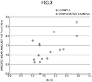
- the graph in Fig. 3 shows a relationship between the ratio (ID/IG) and the specific wear amount of the amorphous carbon layer in each of the examples and the comparative examples (except for those where the hardness of the first amorphous carbon layer was greater than that of the alumina-based sintered body forming the first valve body).
- Example 1 First Valve Body Second Valve Body Evaluation Base Material Hardness [GPa] Base Material Coating Layer Shaved Lubrican t Layer Specific Wear *10 -7 mm 3 /N ⁇ m Material Hardness [GPa] Ratio (ID/I G) N/(N+S) Example 1 Alumina-based Sintered Body 31 Alumina-based Sintered Body DLC 20 1.1 0.31 Second Valve Body ⁇ 0.8 Example 2 Alumina-based Sintered Body 31 Alumina-based Sintered Body DLC 29 1.3 0.26 Second Valve Body ⁇ 1.6 Example 3 Alumina-based Sintered Body 31 Alumina-based Sintered Body DLC 16 1.4 0.27 Second Valve Body ⁇ 0.8 Example 4 Alumina-based Sintered Body 31 Alumina-based Sintered Body DLC 25 1.3 0.23 Second Valve Body ⁇ 1.0 Example 5 Alumina-based Sintered Body 31 Alumina-based Sintered Body DLC 14 1.3 0.28 Second Valve Body ⁇ 0.6 Example 6 Alumina-based Sintered Body 31 Alumina-based Sintered Body DLC 19 1.3 0.
Landscapes
- Chemical & Material Sciences (AREA)
- Engineering & Computer Science (AREA)
- Organic Chemistry (AREA)
- Materials Engineering (AREA)
- Mechanical Engineering (AREA)
- Ceramic Engineering (AREA)
- General Engineering & Computer Science (AREA)
- Metallurgy (AREA)
- Chemical Kinetics & Catalysis (AREA)
- Structural Engineering (AREA)
- General Chemical & Material Sciences (AREA)
- Inorganic Chemistry (AREA)
- Physics & Mathematics (AREA)
- Plasma & Fusion (AREA)
- Sliding Valves (AREA)
- Multiple-Way Valves (AREA)
- Domestic Plumbing Installations (AREA)
- Manufacturing & Machinery (AREA)
Abstract
Description
- The present invention relates to a faucet valve.
- In order to fabricate a faucet valve with high rigidity and high corrosion resistance at a low cost, use of inexpensive alumina has been studied. A faucet valve has been known in which one valve body is coated with an amorphous carbon layer in order to improve the slidability of the faucet valve (for example, Japanese Patent Application Publication No.
Hei 9-126239 Hei 9-292039 2004-183699 - An object of the present invention is to provide a faucet valve in which ceramic-made valve bodies slide on each other with water in between, the faucet valve achieving excellent slide performance.
- The structure of the amorphous carbon layer is an amorphous structure in which a diamond-like structure and a graphite-like structure are mixed together. The ratio between the diamond-like structure and the graphite-like structure varies one another. The inventors have focused on a characteristic that the employment of a film structure softer than an alumina valve body for the amorphous carbon layer makes it possible to make wear debris relatively soft even in a case where the amorphous carbon layer is worn. In other words, the inventors selected an amorphous carbon layer whose hardness was equal to or less than that of its counterpart material, and deliberately worn the amorphous carbon layer by sliding the amorphous carbon layer. Furthermore, the inventors have managed to select the amorphous carbon layer that easily reacts with water. To put it specifically, the inventors set an ID/IG ratio in the amorphous carbon layer, measured by Raman spectroscopy, within a predetermined range, and thereby made it easy for the amorphous carbon layer to react with water. Consequently, the inventors have found that: such an amorphous carbon layer can be selectively worn when one valve body is slid over the other valve body with a very small amount of water in between; and the amorphous carbon layer makes it possible to relatively increase an amount of lubricant layer formed between the first and second valve bodies. The inventors have further got a finding that the selective wear and the increased amount of lubricant layer makes it possible to effectively inhibit progress in wear of the first and second valve bodies. Eventually, the inventors have completed the present invention based on these findings.
- In other words, the present invention provides a faucet valve including: a first valve body including a first slide surface, and formed from an alumina-based sintered body; and a second valve body including a second slide surface, and formed from an alumina-based sintered body, the first and second slide surfaces at least partially being in contact with each other with water in between, wherein: a first amorphous carbon layer is provided to at least part of the second slide surface; hardness of the first amorphous carbon layer is equal to or less than that of the alumina-based sintered body forming the first valve body; and in the first amorphous carbon layer, a ratio (ID/IG) of a D peak to a G peak, measured by Raman spectroscopy, is greater than 0.5 but less than 1.9.
- The present invention can provide the faucet valve in which ceramic-made valve bodies slide on each other with water in between, the faucet valve achieving excellent slide performance.
-
-
Fig. 1 is an exploded perspective view illustrating a faucet valve according to an embodiment of the present invention with its constituent valve bodies separated from each other. -
Fig. 2 is a magnified cross-sectional view illustrating a structure of a second valve body. -
Fig. 3 is a graph showing a relationship between ratio (ID/IG) and a wear amount of an amorphous carbon layer in each of examples and comparative examples (except for those where hardness of a first amorphous carbon layer was greater than that of an alumina-based sintered body forming a first valve body). -
Fig. 4 shows photomicrographs of first valve bodies (balls) taken after a ball-on-disk friction wear test. -
Figs. 5A and 5B are photomicrographs of the first valve bodies (balls) of Example 3 and Comparative Example 3, respectively, taken after the ball-on-disk friction wear test. - A faucet valve of the present invention includes: a first valve body including a first slide surface, and formed from an alumina-based sintered body; and a second valve body including a second slide surface, and formed from an alumina-based sintered body. At least parts of the respective first and second slide surfaces are in contact with each other with water in between. In addition, a first amorphous carbon layer is provided to at least part of the second slide surface. The hardness of the first amorphous carbon layer is equal to or less than that of the alumina-based sintered body forming the first valve body. The hardness of the amorphous carbon layer is measured, for example, by nano-indentation. The hardness of the first amorphous carbon layer is preferably 30 GPa or less, and more preferably 25 GPa or less. On the other hand, the hardness of the first amorphous carbon layer is preferably greater than 8 GPa. This hardness of the first amorphous carbon layer makes it possible to form a lubricant layer easily, and to thus inhibit a progress in wear of the first amorphous carbon layer.
- Furthermore, in the first amorphous carbon layer, a ratio (ID/IG) of a D peak to a G peak, measured by Raman spectroscopy, is greater than 0.5, but less than 1.9. The ratio (ID/IG) in the first amorphous carbon layer is preferably greater than 1.0 but less than 1.5, and more preferably not less than 1.1 but not greater than 1.4. The ratio (ID/IG) in the first amorphous carbon layer set within this range makes it possible to form the lubricant layer easily, and to thus inhibit the progress in wear of the first amorphous carbon layer. Moreover, in the first amorphous carbon layer, N/(N+S) measured by Raman spectroscopy is preferably less than 0.33, and more preferably 0.31 or less. The N/(N+S) is much more preferably 0.23 or greater. The N/(N+S) in the first amorphous carbon layer set within this range makes it possible to form the lubricant layer easily, and to thus inhibit the progress in wear of the first amorphous carbon layer.
- In addition, the surface roughness (arithmetic average roughness Ra) of the first amorphous carbon layer is preferably less than 0.3 µm, more preferably less than 0.2 µm, and much more preferably less than 0.1 µm. The surface roughness of the first amorphous carbon layer set within this range makes it possible to decrease the wear amount of the first amorphous carbon layer.
- Moreover, the first amorphous carbon layer may further contain a third element (s) such as Si, Cl, N, F and O. The first amorphous carbon layer containing the third element(s) makes it possible to decrease the coefficient of friction, to reduce lever operating force more, and to slide the second valve body over the first valve body smoothly.
- The thickness of the first amorphous carbon layer is 0.5µm or greater, and more preferably 1 µm or greater. The thickness of the first amorphous carbon layer set within this range makes it possible to form the lubricant layer well even in a case where the first amorphous carbon layer wears slightly.
- Furthermore, for the purpose of enhancing the adhesion between the second valve body and the first amorphous carbon layer, an intermediate layer may be provided between the first amorphous carbon layer and the second valve body. Moreover, in this case, a composite layer or an inclination layer may be provided between the first amorphous carbon layer and the intermediate layer. In this respect, the composite layer is a layer that contains amorphous carbon and the same intermediate layer material as that contained in the intermediate layer. In this composite layer, the amorphous carbon and the intermediate layer material may be stacked alternately. Otherwise, the amorphous carbon and the intermediate layer material may be mixed together. The inclination layer is a layer that contains amorphous carbon and the same intermediate layer material as that contained in the intermediate layer, where the content of the intermediate layer material decreases from the intermediate layer toward the first amorphous carbon layer, and/or, where the content of the amorphous carbon increases from the intermediate layer toward the first amorphous carbon layer. The composite layer and/or the inclination layer can be checked by element mapping using an energy dispersive X-ray analyzer, for example. The intermediate layer material contained in the intermediate layer is not limited to a particular one, as long as it can enhance the adhesion between the second valve body and the first amorphous carbon layer. Examples of the intermediate layer material include Cr, W, Ti, Si and Al.
- A second amorphous carbon layer may be provided to at least part of the first slide surface. In this case, the hardness of the first amorphous carbon layer and the hardness of the second amorphous carbon layer may be equal to or different from each other.
- Moreover, the second amorphous carbon layer may further contain a third element (s) such as Si, Cl, N, F and O. The second amorphous carbon layer containing the third element(s) makes it possible to decrease the coefficient of friction, to reduce the lever operating force more, and to slide the second valve body over the first valve body smoothly.
- Besides, for the purpose of enhancing the adhesion between the first valve body and the second amorphous carbon layer, an intermediate layer may be provided between the second amorphous carbon layer and the first valve body. Moreover, in this case, a composite layer or an inclination layer may be provided between the second amorphous carbon layer and the intermediate layer. In this respect, the composite layer is a layer that contains amorphous carbon and the same intermediate layer material as that contained in the intermediate layer. The inclination layer is a layer that contains amorphous carbon and the same intermediate layer material as that contained in the intermediate layer, where the content of the intermediate layer material decreases from the intermediate layer toward the second amorphous carbon layer. The intermediate layer material contained in the intermediate layer is not limited to a particular one, as long as it can enhance the adhesion between the first valve body and the second amorphous carbon layer. Examples of the intermediate layer material include Cr, W, Ti, Si and Al.
- The alumina-based sintered body forming the first and second valve bodies contains alumina (Al2O3) as its main component. A commercially-available sintered body with sufficient strength and relatively few pores may be used as the alumina-based sintered body. The alumina-based sintered body containing alumina (Al2O3) as its main component may be used with an alumina (Al2O3) purity of 50% or greater, preferably 90% or greater, and more preferably 96% or greater.
- The faucet valve according to the present invention will be hereinbelow described citing an example. The present invention, however, is not limited to this.
Fig. 1 is an exploded perspective view illustrating thefaucet valve 100 according to an embodiment of the present invention with its constituent valve bodies separated from each other. Thefaucet valve 100 includes the first valve body and a second valve body. Descriptions will be herein provided for an example where: the second valve body is amovable valve body 20; and the first valve body is a fixedvalve body 30. Nevertheless, the first and second valve bodies may be themovable valve body 20 and the fixedvalve body 30, respectively. Themovable valve body 20 includes asecond slide surface 21. The fixedvalve body 30 includes afirst slide surface 31. In thefaucet valve 100, at least parts of the respective first and second slide surfaces 31, 21 are in contact with each other with water in between. The movable valve body 20 (the second valve body) is, for example, a disk-shaped valve body that includes afluid passage 22 penetrating through themovable valve body 20 between the upper and lower surfaces, and is formed from an alumina-based sintered body. In addition, as illustrated inFig. 2 , the slide surface 21 (the second slide surface) is formed on the surface of themovable valve body 20 by depositing an amorphous carbon layer 24 (a first amorphous carbon layer) on the surface of themovable valve body 20 with anintermediate layer 23 in between. - Furthermore, the fixed
valve body 30 is formed as a disk-shaped valve body that is larger than themovable valve body 20, and that includes, for example, afluid passage 32 and twofluid discharge ports valve body 30 between the upper and lower surfaces. - Moreover, the slide surfaces 21, 31 are in intimate contact with each other with no lubricant in between. When the
movable valve body 20 is slid over the fixedvalve body 30 by moving a lever (not illustrated), thefluid passage respective valve bodies movable valve body 20 and the fixedvalve body 30 controls a flow rate of supplied fluid, and controls opening degrees of the respectivefluid discharge ports - In this respect, since the amorphous carbon layer with excellent self-lubricating properties is deposited on the
slide surface 21 of themovable valve body 20, themovable valve body 20 can be smoothly slid over the fixedvalve body 30 while avoiding much wear of the fixedvalve body 30 and reducing a lever operating force regardless of no lubricant between the slide surfaces 21, 31. - A ratio of a D peak to a G peak and N/ (N+S) in the amorphous carbon layer can be obtained using the following method.
- To begin with, laser Raman spectroscopy is performed to obtain a Raman spectrum using a laser Raman microscope (RAMAN Touch VIS-NIR (made by Nanophoton)). The measurement magnification is at 20 times; and the measurement diameter is at ∼1 micrometer. As a light source, a laser beam with a 532-nanometer wavelength and a 0.5-mW power is used. The exposure time is at 1 second, and the number of times of accumulation is at 10. The diffraction grating is at 600 gr/mm.
- The analysis is performed using analysis software like OriginPro 2016 (produced by Lightstone Corporation). The background is removed from the waveform of the obtained Raman spectrum. Waveform separation is performed on two peaks around the wavenumbers 1350 cm-1 and 1530 cm-1 (respectively referred to as a "D band" and a "G band") by a curve fitting method using a Gaussian function. The areas of the D and G bands are respectively denoted by ID and IG, and a ratio between the areas of the two respective bands is denoted by ratio (ID/IG). An intensity ratio N/ (N+S) is obtained where: S denotes the intensity of a Raman scattered light component at a peak position of the G band in the Raman spectrum; and N is the intensity of a fluorescent component.
- The hardness of the amorphous carbon layer can be obtained using the following method.
- The hardness of the amorphous carbon layer is measured using an ultra-small indentation hardness tester (ENT-2100 made by Elionix Inc. with a triangular-pyramid diamond indenter). For the measurement, a test load is at 5mN, a step interval is at 20 msec, and a retention time is at 1000 msec. After the hardness is measured 10 times, the film hardness is obtained as an average of 8 measurement values that are obtained by excluding a maximum value and a minimum value from the 10 measurement values.
- The surface roughness of the amorphous carbon layer can be obtained using the following method.
- The surface roughness is measured using a surface roughness tester (SURFCOM 1500, made by Tokyo Seimitsu, Co., Ltd.) based on JIS B 0601: 2001, and is obtained as arithmetic average roughness (Ra).
- More detailed descriptions will be provided for the present invention using the following examples. It should be noted that the present invention is not limited to these examples.
- An alumina-based sintered body with a 96-percent alumina purity was used as the base material of the second valve body. The slide surface (the second slide surface) of the sintered body was ground to have a predetermined surface roughness.
- An unbalanced magnetron sputtering system was used. The base material was baked using a heater at a predetermined temperature. The surface of the base material was etched with Ar plasma. Thereafter, the intermediate layer and the amorphous carbon layer were deposited on the resultant base material in this order. Chromium and tungsten were used as the materials of the intermediate layer. Solid carbon and hydrocarbon (methane and/or acetylene) gas were used as the materials of the amorphous carbon layer. The samples (the second valve bodies) of Examples 1 to 7 as well as Comparative Examples 1, 4 to 7 and 9 were obtained by controlling the deposition pressure, the hydrocarbon gas mixture ratio, the bias voltage to be applied to the base material, and the like. In each sample, the film thickness of the amorphous carbon layer was within a range of 0.5 µm to 2 µm. Incidentally, the same sample as prepared for Example 5 was used as the second valve body of Comparative Example 1.
- A plasma-enhanced chemical vapor deposition (CVD) system was used. Radio-frequency plasma and direct-current plasma were used as the plasma source. The surface of the base material was etched with Ar plasma. Thereafter, the intermediate layer and the amorphous carbon layer were deposited on the resultant base material in this order. Silicon carbide was used as the material of the intermediate layer. Hydrocarbon (methane and/or acetylene) gas was used as the material of the amorphous carbon layer. The samples of Example 8 and Comparative Example 2 were obtained by controlling the deposition pressure, the hydrocarbon gas mixture ratio, the bias voltage to be applied to the base material, and the like. In each sample, the film thickness of the amorphous carbon layer was at 1 µm.
- A plasma-enhanced chemical vapor deposition (CVD) system was used. Thermal-filament plasma was used as the plasma source. The surface of the base material was etched with Ar plasma. Thereafter, the intermediate layer and the amorphous carbon layer were deposited on the resultant base material in this order. Silicon carbide was used as the material of the intermediate layer. Hydrocarbon (methane and/or acetylene) gas was used as the material of the amorphous carbon layer. The sample of Example 9 was obtained by controlling the deposition pressure, the hydrocarbon gas mixture ratio, the bias voltage to be applied to the base material, and the like. The film thickness of the amorphous carbon layer was at 1 µm.
- A plasma-enhanced chemical vapor deposition (CVD) system was used. A linear ion source was used to generate ions. The surface of the base material was etched with Ar plasma. Thereafter, the intermediate layer and the amorphous carbon layer were deposited on the resultant base material in this order. The intermediate layer was deposited by unbalanced magnetron sputtering. Chromium was used as the material of the intermediate layer. Hydrocarbon (methane and/or acetylene) gas was used as the material of the amorphous carbon layer. The sample of Example 10 was obtained by controlling the deposition pressure, the hydrocarbon gas mixture ratio, the bias voltage to be applied to the base material, and the like. The film thickness of the amorphous carbon layer was at 1 µm.
- An arc ion plating system was used. The base material was baked using a heater at a predetermined temperature. The surface of the base material was etched with Ar plasma. Thereafter, the intermediate layer and the amorphous carbon layer were deposited on the resultant base material in this order. Titanium was used as the material of the intermediate layer. Solid carbon was used as the material of the amorphous carbon layer. The samples of Examples 3 and 8 were obtained by controlling the deposition pressure, the bias voltage to be applied to the base material, and the like. In each sample, the film thickness of the amorphous carbon layer was at 1 µm.
- Each sample prepared as discussed above was analyzed and evaluated as follows.
- For each sample, Laser Raman spectroscopic analysis was performed with the following conditions, and a Raman spectrum was obtained.
- Apparatus: a laser Raman microscope, RAMAN Touch VIS-NIR (made by Nanophoton)
- Conditions: Measurement Magnification at 20 times Measurement diameter at ∼ 1 µm Light Source
- Laser Wavelength at 532 nm
- Laser Power at 0.5 mW
Number of times of Accumulation at 10 Diffraction Grating at 600 gr/mm - OriginPro 2016 (produced by Lightstone Corporation) was used as the analysis software.
- For each sample, the background was removed from the waveform of the obtained Raman spectrum. Waveform separation was performed on the two peaks around the wavenumbers 1350 cm-1 and 1530 cm-1 (respectively referred to as a "D band" and a "G band") by the curve fitting method using the Gaussian function. The areas of the D and G bands were respectively denoted by ID and IG, and a ratio between the areas of the two respective bands is denoted by ratio (ID/IG).
- An intensity ratio N/(N+S) is obtained where: S denotes the intensity of a Raman scattered light component at the peak position of the G band in the Raman spectrum; and N denotes the intensity of the fluorescent component.
- For each sample, the hardness of the amorphous carbon layer was measured using a Nano-indentation tester (ENT-2100 made by Elionix Inc. with a triangular-pyramid diamond indenter). The measurement conditions were the test load at 5mN, the step interval at 20 msec, and the retention time at 1000 msec. After the hardness was measured 10 times, the film hardness value was obtained as an average of 8 measurement values that were obtained by excluding a maximum value and a minimum value from the 10 measurement values.
- For each sample, the arithmetic average roughness (Ra) was measured using a surface roughness tester (SURFCOM 1500, made by Tokyo Seimitsu, Co., Ltd.). The measurement conditions were set based on JIS B 0601: 2001.
- As for the sample of Comparative Example 3, the surface roughness was measured at 0.2 µm, and the surface was rough. As for each of the other samples, the surface roughness was measured at 0.1 µm, and the surface was smooth.
- A ball-on-disk friction wear test was performed with the following conditions. The above-obtained samples of Examples 1 to 6 and Comparative Examples 1 to 3 were treated as the second valve body. An alumina-based sintered body or a stainless steel (SUS) was used as the material of a ball (the first valve body) .
- Tester: a friction wear tester, FPR-2100 (made by Rhesca Co., Ltd.)
- Conditions: Load at 400 g
Speed at 10 mm/s
Oscillation Width at 5 mm
Number of Reciprocations at 5000
Oscillation Environment- Room Temperature
- Underwater
- For each sample, the cross-sectional area of an abrasion mark on the amorphous carbon layer (the first amorphous carbon layer) after the friction wear test was measured using a laser microscope (OLS-4100, made by Olympus Corporation). Using the obtained cross-sectional area of the abrasion mark, the specific wear amount was calculated based of the following equation:

- For each sample, after the wear amount calculation, the ball (the first valve body) was cleaned with ethanol, and was subsequently dried. After that, a wear track made on the ball (the first valve body) in the friction wear test was observed using a digital microscope (DVM6, made by Leica Microsystems). To put it specifically, the abrasion mark was observed with the following conditions: an exposure time at 33 ms; color gains at R400, G256 and B350; a color saturation at 25; a luminance brightness for CXI illumination at 60; no lambda plate used. Samples in which a lubricant layer derived from the amorphous carbon layer was observed were evaluated as being good, which is represented with ○ (white circle). Samples in which no lubricant layer derived from the amorphous carbon layer was observed were evaluated as being poor, which is represented with × (cross).
Figs. 5A and 5B show results of the observations of the lubricant layers of Example 3 and Comparative Examples 3, respectively. - For each sample, a specimen for observation was obtained by: cutting the sample after the deposition; and polishing the obtained cross section. The cross sections of the intermediate layer and the amorphous carbon layer were observed using a scanning electron microscope (S-4100, made by Hitachi, Ltd.). Using an energy dispersive X-ray analyzer (EMAX-7000, made by Horiba, Ltd.), an element map was produced to show the spatial distribution of carbon and intermediate layer elements in the field of view where each layer were observed. Thus, the existence of the amorphous carbon layer and the composite layer of the intermediate layer elements was confirmed in every sample.
- Table 1 shows the results of the above-discussed analysis and evaluation. In addition, the graph in
Fig. 3 shows a relationship between the ratio (ID/IG) and the specific wear amount of the amorphous carbon layer in each of the examples and the comparative examples (except for those where the hardness of the first amorphous carbon layer was greater than that of the alumina-based sintered body forming the first valve body). These results shows that: in the case where the first valve body was formed from the alumina-based sintered body, the ratio (ID/IG) fell within a predetermined range (greater than 0.5 but less than 1.9), the lubricant layer was accordingly formed sufficiently, and the specific wear amount was small (Examples 1 to 6). In a case where the ratio (ID/IG) fell out of the range, no lubricant layer was formed, and the specific wear amount was large (Comparative Examples 2, 4 to 6, and 9). Meanwhile, in a case where the first valve body was formed from SUS, the amorphous carbon layer did not wear, and wear debris of the SUS were produced (Comparative Example 1).[Table 1] First Valve Body Second Valve Body Evaluation Base Material Hardness [GPa] Base Material Coating Layer Shaved Lubrican t Layer Specific Wear *10-7mm3/N·m Material Hardness [GPa] Ratio (ID/I G) N/(N+S) Example 1 Alumina-based Sintered Body 31 Alumina-based Sintered Body DLC 20 1.1 0.31 Second Valve Body ○ 0.8 Example 2 Alumina-based Sintered Body 31 Alumina-based Sintered Body DLC 29 1.3 0.26 Second Valve Body ○ 1.6 Example 3 Alumina-based Sintered Body 31 Alumina-based Sintered Body DLC 16 1.4 0.27 Second Valve Body ○ 0.8 Example 4 Alumina-based Sintered Body 31 Alumina-based Sintered Body DLC 25 1.3 0.23 Second Valve Body ○ 1.0 Example 5 Alumina-based Sintered Body 31 Alumina-based Sintered Body DLC 14 1.3 0.28 Second Valve Body ○ 0.6 Example 6 Alumina-based Sintered Body 31 Alumina-based Sintered Body DLC 19 1.3 0.28 Second Valve Body ○ 1.5 comparative example 1 SUS - Alumina-based Sintered Body DLC 14 1.3 0.28 First Valve Body × 0.0 comparative example 2 Alumina-based Sintered Body 31 Alumina-based Sintered Body DLC 16 1.9 0.33 Second Valve Body × 2.2 comparative example 3 Alumina-based Sintered Body 31 Alumina-based Sintered Body DLC 41 0.5 0.46 First Valve Body × 2.8 Example 7 Alumina-based Sintered Body 31 Alumina-based Sintered Body DLC 9 1.6 0.48 Second Valve Body ○ 0.8 Example 8 Alumina-based Sintered Body 31 Alumina-based Sintered Body DLC 13 1.1 0.32 Second Valve Body ○ 0.6 Example 9 Alumina-based Sintered Body 31 Alumina-based Sintered Body DLC 11 1.8 0.60 Second Valve Body ○ 1.2 Example 10 Alumina-based Sintered Body 31 Alumina-based Sintered Body DLC 25 1.0 0.24 Second Valve Body ○ 1.8 comparative example 4 Alumina-based Sintered Body 31 Alumina-based Sintered Body DLC 8 2.2 0.62 Second Valve Body × 1.3 comparative example 5 Alumina-based Sintered Body 31 Alumina-based Sintered Body DLC 8 2.3 0.58 Second Valve Body × 1.3 comparative example 6 Alumina-based Sintered Body 31 Alumina-based Sintered Body DLC 7 2.9 0.59 Second Valve Body × 2.0 comparative example 7 Alumina-based Sintered Body 31 Alumina-based Sintered Body DLC 34 1.5 0.30 First Valve Body × 2.5 comparative example 8 Alumina-based Sintered Body 31 Alumina-based Sintered Body DLC 35 1.0 0.74 First Valve Body × 1.4 comparative example 9 Alumina-based Sintered Body 31 Alumina-based Sintered Body DLC 7 2.9 0.59 Second Valve Body × 2.7
Claims (15)
- A faucet valve comprising:a first valve body including a first slide surface, and formed from an alumina-based sintered body; anda second valve body including a second slide surface, and formed from an alumina-based sintered body, the first and second slide surfaces at least partially being in contact with each other with water in between, whereinat least part of the second slide surface is formed from a first amorphous carbon layer,hardness of the first amorphous carbon layer is equal to or less than that of the alumina-based sintered body forming the first valve body, andin the first amorphous carbon layer, a ratio (ID/IG) of a D peak to a G peak, measured by Raman spectroscopy, is greater than 0.5 but less than 1.9, or greater than 1.0 but less than 1.5, or 1.1 or greater but 1.4 or less.
- The faucet valve according to claim 1, wherein
N/(N+S) measured by Raman spectroscopy is less than 0.33 or 0.31 or less. - The faucet valve according to claim 1 or 2, wherein the N/(N+S) is 0.23 or greater.
- The faucet valve according to claims 1 to 3, wherein
the hardness of the first amorphous carbon layer is 30 GPa or less or 25 GPa or less. - The faucet valve according to claims 1 to 4, wherein
surface roughness of the first amorphous carbon layer is less than 0.3 µm, or less than 0.2 µm, or 0.1µm or less. - The faucet valve according to claims 1 to 5, wherein
a second amorphous carbon layer is provided to at least part of the first slide surface. - The faucet valve according to claims 1 to 6, wherein
the first amorphous carbon layer further contains at least one element selected from the group consisting of Si, Cl, F, N and O as a third element, or
the second amorphous carbon layer further contains at least one element selected from the group consisting of Si, Cl, F, N and O as a third element. - The faucet valve according to claims 6 to 7, further comprising a first intermediate layer between the second amorphous carbon layer and the first valve body.
- The faucet valve according to claim 8, further comprising a first composite layer or a first inclination layer between the second amorphous carbon layer and the first intermediate layer, wherein
the first composite layer is a layer containing amorphous carbon and the same intermediate layer material as that contained in the first intermediate layer, and
the first inclination layer is a layer containing amorphous carbon and the same intermediate layer material as that contained in the first intermediate layer, where a content of the intermediate layer material decreases from the first intermediate layer toward the second amorphous carbon layer. - The faucet valve according to claims 1 to 9, further comprising a second intermediate layer between the first amorphous carbon layer and the second valve body.
- The faucet valve according to claim 10, further comprising a second composite layer or a second inclination layer between the first amorphous carbon layer and the second intermediate layer, wherein
the second composite layer is a layer that contains amorphous carbon and the same intermediate layer material as that contained in the second intermediate layer, and
the second inclination layer is a layer that contains amorphous carbon and the same intermediate layer material as that contained in the second intermediate layer, where a content of the intermediate layer material decreases from the second intermediate layer toward the first amorphous carbon layer. - The faucet valve according to claims 8 to 11, wherein the first intermediate layers contain at least one intermediate layer material selected from the group consisting of Cr, W, Ti, Si and Al.
- The faucet valve according to claims 1 to 12, wherein the hardness of the first amorphous carbon layer is greater than 8 GPa.
- Use of an amorphous carbon layer as at least part of a slide surface in the faucet valve according to any one of claims 1 to 13, for forming a lubricant layer and improving the slidability of the faucet valve.
- A method for manufacturing a faucet valve, comprising the steps of:forming a first valve body from an alumina-based sintered body;providing a first slide surface in the first valve body;forming a second valve body from an alumina-based sintered body;providing, in the second valve body, a second slide surface at least part of which is formed from a first amorphous carbon layer having a hardness equal to or less than that of the alumina-based sintered body forming the first valve body,whereby the first and second slide surfaces are at least partially in contact with each other with water in between, andwhereby a D peak to a G peak, measured by Raman spectroscopy, is set greater than 0.5 but less than 1.9, or greater than 1.0 but less than 1.5, or 1.1 or greater but 1.4 or less.
Applications Claiming Priority (1)
| Application Number | Priority Date | Filing Date | Title |
|---|---|---|---|
| JP2017012183 | 2017-01-26 |
Publications (2)
| Publication Number | Publication Date |
|---|---|
| EP3354949A1 true EP3354949A1 (en) | 2018-08-01 |
| EP3354949B1 EP3354949B1 (en) | 2020-03-11 |
Family
ID=61017809
Family Applications (1)
| Application Number | Title | Priority Date | Filing Date |
|---|---|---|---|
| EP18152455.4A Active EP3354949B1 (en) | 2017-01-26 | 2018-01-19 | Faucet valve |
Country Status (6)
| Country | Link |
|---|---|
| US (1) | US10697552B2 (en) |
| EP (1) | EP3354949B1 (en) |
| JP (1) | JP7034436B2 (en) |
| CN (1) | CN108386567B (en) |
| SG (1) | SG10201800574TA (en) |
| TW (1) | TWI676756B (en) |
Cited By (2)
| Publication number | Priority date | Publication date | Assignee | Title |
|---|---|---|---|---|
| EP3828308A1 (en) * | 2019-11-29 | 2021-06-02 | Toto Ltd. | Wet-area device and method for manufacturing wet-area device |
| EP3828310A1 (en) * | 2019-11-29 | 2021-06-02 | Toto Ltd. | Wet-area device and method for manufacturing wet-area device |
Families Citing this family (1)
| Publication number | Priority date | Publication date | Assignee | Title |
|---|---|---|---|---|
| JP6901722B2 (en) * | 2017-03-30 | 2021-07-14 | 東京エレクトロン株式会社 | How to manufacture fluid heaters, fluid controllers, and fluid heaters |
Citations (6)
| Publication number | Priority date | Publication date | Assignee | Title |
|---|---|---|---|---|
| JPH09126239A (en) | 1995-10-31 | 1997-05-13 | Kyocera Corp | Sliding device |
| JPH09292039A (en) | 1996-04-26 | 1997-11-11 | Kyocera Corp | Disc valve |
| EP1096189A1 (en) * | 1999-10-27 | 2001-05-02 | Ngk Spark Plug Co., Ltd | Valve with ceramic valve seats |
| EP1266879A2 (en) * | 2001-06-13 | 2002-12-18 | Sumitomo Electric Industries Co., Ltd. | Amorphous carbon coated tools and method of producing the same |
| JP2004183699A (en) | 2002-11-29 | 2004-07-02 | Sumitomo Electric Ind Ltd | Hot water faucet valve and manufacturing method thereof |
| WO2016042630A1 (en) * | 2014-09-17 | 2016-03-24 | 日本アイ・ティ・エフ株式会社 | Coating film, manufacturing method for same, and pvd device |
Family Cites Families (22)
| Publication number | Priority date | Publication date | Assignee | Title |
|---|---|---|---|---|
| JP2830544B2 (en) * | 1991-10-25 | 1998-12-02 | 松下電器産業株式会社 | Magnetic recording media |
| DE19580519B3 (en) * | 1994-03-31 | 2014-03-06 | Ntn Corp. | valve assembly |
| JP3612098B2 (en) * | 1994-12-27 | 2005-01-19 | 京セラ株式会社 | Disc valve |
| EP2000560B1 (en) | 1999-07-08 | 2013-10-02 | Sumitomo Electric Industries, Ltd | Hard coating and coated member |
| US6453946B2 (en) * | 2000-03-10 | 2002-09-24 | Rheodyne, Lp | Long lifetime fluid switching valve |
| JP2003212642A (en) * | 2001-11-14 | 2003-07-30 | Ngk Spark Plug Co Ltd | Alumina sintered compact, insertable insert and cutting tool |
| JP2003314712A (en) * | 2002-04-25 | 2003-11-06 | Sumitomo Electric Ind Ltd | Hot water valve |
| US6904935B2 (en) | 2002-12-18 | 2005-06-14 | Masco Corporation Of Indiana | Valve component with multiple surface layers |
| JP2004353759A (en) | 2003-05-29 | 2004-12-16 | Toto Ltd | Abnormal noise cancellation method for disc valve and faucet |
| JP3764742B2 (en) * | 2004-05-10 | 2006-04-12 | 京セラ株式会社 | Sliding device and faucet valve |
| JP4264400B2 (en) * | 2004-10-06 | 2009-05-13 | 三菱重工業株式会社 | Soft amorphous carbon film and method for producing the same |
| JP5051453B2 (en) | 2004-11-25 | 2012-10-17 | 株式会社豊田中央研究所 | Amorphous carbon film, method for forming the same, and high wear-resistant sliding member provided with amorphous carbon film |
| JP4220968B2 (en) | 2005-01-06 | 2009-02-04 | 三菱重工業株式会社 | Amorphous carbon film-coated substrate and amorphous carbon film forming method |
| US20100276617A1 (en) * | 2008-02-14 | 2010-11-04 | Shimadzu Corporation | Flow channel switching valve |
| CN102227842B (en) | 2008-11-28 | 2014-03-12 | 日产自动车株式会社 | Sealing structure and fuel cell comprising sealing structure |
| CA2800269A1 (en) | 2011-02-09 | 2012-08-16 | Incubation Alliance, Inc. | Method for producing multilayer graphene-coated substrate |
| JP5904537B2 (en) | 2011-04-20 | 2016-04-13 | Ntn株式会社 | Method for forming amorphous carbon film |
| US20140079910A1 (en) * | 2011-05-10 | 2014-03-20 | Kazuo Tsugawa | Carbon film laminate, method of manufacturing said laminate, and lubricant using said laminate |
| JP6201125B2 (en) | 2013-04-18 | 2017-09-27 | 日本アイ・ティ・エフ株式会社 | Ball joint and manufacturing method thereof |
| JP2015187297A (en) * | 2014-03-27 | 2015-10-29 | トヨタ自動車株式会社 | Deposition method of carbon film |
| CN106662259A (en) | 2014-07-09 | 2017-05-10 | Nok株式会社 | Valve for rubber layered sealing |
| CN110397735B (en) * | 2015-08-10 | 2020-12-22 | 日本Itf株式会社 | Piston ring |
-
2018
- 2018-01-12 US US15/870,327 patent/US10697552B2/en active Active
- 2018-01-18 JP JP2018006470A patent/JP7034436B2/en active Active
- 2018-01-19 EP EP18152455.4A patent/EP3354949B1/en active Active
- 2018-01-22 CN CN201810057924.3A patent/CN108386567B/en active Active
- 2018-01-22 SG SG10201800574TA patent/SG10201800574TA/en unknown
- 2018-01-24 TW TW107102457A patent/TWI676756B/en active
Patent Citations (6)
| Publication number | Priority date | Publication date | Assignee | Title |
|---|---|---|---|---|
| JPH09126239A (en) | 1995-10-31 | 1997-05-13 | Kyocera Corp | Sliding device |
| JPH09292039A (en) | 1996-04-26 | 1997-11-11 | Kyocera Corp | Disc valve |
| EP1096189A1 (en) * | 1999-10-27 | 2001-05-02 | Ngk Spark Plug Co., Ltd | Valve with ceramic valve seats |
| EP1266879A2 (en) * | 2001-06-13 | 2002-12-18 | Sumitomo Electric Industries Co., Ltd. | Amorphous carbon coated tools and method of producing the same |
| JP2004183699A (en) | 2002-11-29 | 2004-07-02 | Sumitomo Electric Ind Ltd | Hot water faucet valve and manufacturing method thereof |
| WO2016042630A1 (en) * | 2014-09-17 | 2016-03-24 | 日本アイ・ティ・エフ株式会社 | Coating film, manufacturing method for same, and pvd device |
Cited By (2)
| Publication number | Priority date | Publication date | Assignee | Title |
|---|---|---|---|---|
| EP3828308A1 (en) * | 2019-11-29 | 2021-06-02 | Toto Ltd. | Wet-area device and method for manufacturing wet-area device |
| EP3828310A1 (en) * | 2019-11-29 | 2021-06-02 | Toto Ltd. | Wet-area device and method for manufacturing wet-area device |
Also Published As
| Publication number | Publication date |
|---|---|
| CN108386567A (en) | 2018-08-10 |
| TW201829942A (en) | 2018-08-16 |
| SG10201800574TA (en) | 2018-08-30 |
| JP7034436B2 (en) | 2022-03-14 |
| CN108386567B (en) | 2022-08-02 |
| TWI676756B (en) | 2019-11-11 |
| EP3354949B1 (en) | 2020-03-11 |
| US20180209550A1 (en) | 2018-07-26 |
| JP2018119682A (en) | 2018-08-02 |
| US10697552B2 (en) | 2020-06-30 |
Similar Documents
| Publication | Publication Date | Title |
|---|---|---|
| EP1992715B1 (en) | Amorphous hard carbon coating | |
| EP0884509B1 (en) | Disc valve | |
| KR102444205B1 (en) | razor blade coating | |
| EP3643805A1 (en) | Sliding member and coating film | |
| EP3354949B1 (en) | Faucet valve | |
| EP3828311A1 (en) | Razor blade coating | |
| Payling et al. | Improved quantitative analysis of hard coatings by radiofrequency glow discharge optical emission spectrometry (rf-GD-OES) | |
| Polychronopoulou et al. | Nanostructure, mechanical and tribological properties of reactive magnetron sputtered TiCx coatings | |
| RU2766635C2 (en) | Coated cutting tool | |
| EP0191554B1 (en) | Coated cemented carbides and manufacture thereof | |
| CN101517119B (en) | Hard coating film excellent in lubrication characteristics, process for formation thereof, and tool for the plastic working of metal | |
| Jakubéczyová et al. | Investigation of thin layers deposited by two PVD techniques on high speed steel produced by powder metallurgy | |
| Sampaio et al. | Influence of using different titanium cathodic cage plasma deposition configurations on the mechanical, tribological, and corrosion properties of AISI 304 stainless steel | |
| Lukaszkowicz et al. | Characteristics of CrAlSiN+ DLC coating deposited by lateral rotating cathode arc PVD and PACVD process | |
| KR102476668B1 (en) | Coated Extrusion Tools | |
| EP3075475A1 (en) | Cutting tool | |
| Platnieks et al. | Deposition of silver and titanium co-doped diamond-like carbon films by magnetron sputtering | |
| Gammer et al. | Investigations on the effects of plasma-assisted pre-treatment for plasma-assisted chemical vapour deposition TiN coatings on tool steel | |
| EP3075474A1 (en) | Hard lubricating coating film and hard lubricating coating film-covered tool | |
| EP3842169A1 (en) | Cutting tool | |
| Park et al. | Hard coating by plasma-assisted CVD on plasma nitrided stellite | |
| JPH10130821A (en) | Hard-film-coated small-diameter shank tool made of high speed steel, excellent in wear resistance, and its production | |
| EP3842170A1 (en) | Cutting tool | |
| EP3199660A1 (en) | Laminated hard coating and molding die | |
| Novotný et al. | Analysis of Composite Coating of Deep Drawing Tool. Coatings 2022, 12, 863 |
Legal Events
| Date | Code | Title | Description |
|---|---|---|---|
| PUAI | Public reference made under article 153(3) epc to a published international application that has entered the european phase |
Free format text: ORIGINAL CODE: 0009012 |
|
| STAA | Information on the status of an ep patent application or granted ep patent |
Free format text: STATUS: REQUEST FOR EXAMINATION WAS MADE |
|
| 17P | Request for examination filed |
Effective date: 20180119 |
|
| AK | Designated contracting states |
Kind code of ref document: A1 Designated state(s): AL AT BE BG CH CY CZ DE DK EE ES FI FR GB GR HR HU IE IS IT LI LT LU LV MC MK MT NL NO PL PT RO RS SE SI SK SM TR |
|
| AX | Request for extension of the european patent |
Extension state: BA ME |
|
| RBV | Designated contracting states (corrected) |
Designated state(s): AL AT BE BG CH CY CZ DE DK EE ES FI FR GB GR HR HU IE IS IT LI LT LU LV MC MK MT NL NO PL PT RO RS SE SI SK SM TR |
|
| RIC1 | Information provided on ipc code assigned before grant |
Ipc: C04B 41/87 20060101ALI20190719BHEP Ipc: C23C 16/26 20060101ALI20190719BHEP Ipc: F16K 11/06 20060101ALI20190719BHEP Ipc: C23C 14/06 20060101ALI20190719BHEP Ipc: F16K 25/00 20060101AFI20190719BHEP |
|
| GRAP | Despatch of communication of intention to grant a patent |
Free format text: ORIGINAL CODE: EPIDOSNIGR1 |
|
| STAA | Information on the status of an ep patent application or granted ep patent |
Free format text: STATUS: GRANT OF PATENT IS INTENDED |
|
| INTG | Intention to grant announced |
Effective date: 20190917 |
|
| GRAS | Grant fee paid |
Free format text: ORIGINAL CODE: EPIDOSNIGR3 |
|
| GRAA | (expected) grant |
Free format text: ORIGINAL CODE: 0009210 |
|
| STAA | Information on the status of an ep patent application or granted ep patent |
Free format text: STATUS: THE PATENT HAS BEEN GRANTED |
|
| AK | Designated contracting states |
Kind code of ref document: B1 Designated state(s): AL AT BE BG CH CY CZ DE DK EE ES FI FR GB GR HR HU IE IS IT LI LT LU LV MC MK MT NL NO PL PT RO RS SE SI SK SM TR |
|
| REG | Reference to a national code |
Ref country code: GB Ref legal event code: FG4D |
|
| REG | Reference to a national code |
Ref country code: CH Ref legal event code: EP |
|
| REG | Reference to a national code |
Ref country code: AT Ref legal event code: REF Ref document number: 1243523 Country of ref document: AT Kind code of ref document: T Effective date: 20200315 |
|
| REG | Reference to a national code |
Ref country code: IE Ref legal event code: FG4D |
|
| REG | Reference to a national code |
Ref country code: DE Ref legal event code: R096 Ref document number: 602018002893 Country of ref document: DE |
|
| PG25 | Lapsed in a contracting state [announced via postgrant information from national office to epo] |
Ref country code: FI Free format text: LAPSE BECAUSE OF FAILURE TO SUBMIT A TRANSLATION OF THE DESCRIPTION OR TO PAY THE FEE WITHIN THE PRESCRIBED TIME-LIMIT Effective date: 20200311 Ref country code: NO Free format text: LAPSE BECAUSE OF FAILURE TO SUBMIT A TRANSLATION OF THE DESCRIPTION OR TO PAY THE FEE WITHIN THE PRESCRIBED TIME-LIMIT Effective date: 20200611 Ref country code: RS Free format text: LAPSE BECAUSE OF FAILURE TO SUBMIT A TRANSLATION OF THE DESCRIPTION OR TO PAY THE FEE WITHIN THE PRESCRIBED TIME-LIMIT Effective date: 20200311 |
|
| REG | Reference to a national code |
Ref country code: NL Ref legal event code: MP Effective date: 20200311 |
|
| PG25 | Lapsed in a contracting state [announced via postgrant information from national office to epo] |
Ref country code: GR Free format text: LAPSE BECAUSE OF FAILURE TO SUBMIT A TRANSLATION OF THE DESCRIPTION OR TO PAY THE FEE WITHIN THE PRESCRIBED TIME-LIMIT Effective date: 20200612 Ref country code: BG Free format text: LAPSE BECAUSE OF FAILURE TO SUBMIT A TRANSLATION OF THE DESCRIPTION OR TO PAY THE FEE WITHIN THE PRESCRIBED TIME-LIMIT Effective date: 20200611 Ref country code: HR Free format text: LAPSE BECAUSE OF FAILURE TO SUBMIT A TRANSLATION OF THE DESCRIPTION OR TO PAY THE FEE WITHIN THE PRESCRIBED TIME-LIMIT Effective date: 20200311 Ref country code: SE Free format text: LAPSE BECAUSE OF FAILURE TO SUBMIT A TRANSLATION OF THE DESCRIPTION OR TO PAY THE FEE WITHIN THE PRESCRIBED TIME-LIMIT Effective date: 20200311 Ref country code: LV Free format text: LAPSE BECAUSE OF FAILURE TO SUBMIT A TRANSLATION OF THE DESCRIPTION OR TO PAY THE FEE WITHIN THE PRESCRIBED TIME-LIMIT Effective date: 20200311 |
|
| REG | Reference to a national code |
Ref country code: LT Ref legal event code: MG4D |
|
| PG25 | Lapsed in a contracting state [announced via postgrant information from national office to epo] |
Ref country code: NL Free format text: LAPSE BECAUSE OF FAILURE TO SUBMIT A TRANSLATION OF THE DESCRIPTION OR TO PAY THE FEE WITHIN THE PRESCRIBED TIME-LIMIT Effective date: 20200311 |
|
| PG25 | Lapsed in a contracting state [announced via postgrant information from national office to epo] |
Ref country code: SM Free format text: LAPSE BECAUSE OF FAILURE TO SUBMIT A TRANSLATION OF THE DESCRIPTION OR TO PAY THE FEE WITHIN THE PRESCRIBED TIME-LIMIT Effective date: 20200311 Ref country code: EE Free format text: LAPSE BECAUSE OF FAILURE TO SUBMIT A TRANSLATION OF THE DESCRIPTION OR TO PAY THE FEE WITHIN THE PRESCRIBED TIME-LIMIT Effective date: 20200311 Ref country code: LT Free format text: LAPSE BECAUSE OF FAILURE TO SUBMIT A TRANSLATION OF THE DESCRIPTION OR TO PAY THE FEE WITHIN THE PRESCRIBED TIME-LIMIT Effective date: 20200311 Ref country code: IS Free format text: LAPSE BECAUSE OF FAILURE TO SUBMIT A TRANSLATION OF THE DESCRIPTION OR TO PAY THE FEE WITHIN THE PRESCRIBED TIME-LIMIT Effective date: 20200711 Ref country code: PT Free format text: LAPSE BECAUSE OF FAILURE TO SUBMIT A TRANSLATION OF THE DESCRIPTION OR TO PAY THE FEE WITHIN THE PRESCRIBED TIME-LIMIT Effective date: 20200805 Ref country code: CZ Free format text: LAPSE BECAUSE OF FAILURE TO SUBMIT A TRANSLATION OF THE DESCRIPTION OR TO PAY THE FEE WITHIN THE PRESCRIBED TIME-LIMIT Effective date: 20200311 Ref country code: RO Free format text: LAPSE BECAUSE OF FAILURE TO SUBMIT A TRANSLATION OF THE DESCRIPTION OR TO PAY THE FEE WITHIN THE PRESCRIBED TIME-LIMIT Effective date: 20200311 Ref country code: SK Free format text: LAPSE BECAUSE OF FAILURE TO SUBMIT A TRANSLATION OF THE DESCRIPTION OR TO PAY THE FEE WITHIN THE PRESCRIBED TIME-LIMIT Effective date: 20200311 |
|
| REG | Reference to a national code |
Ref country code: AT Ref legal event code: MK05 Ref document number: 1243523 Country of ref document: AT Kind code of ref document: T Effective date: 20200311 |
|
| REG | Reference to a national code |
Ref country code: DE Ref legal event code: R097 Ref document number: 602018002893 Country of ref document: DE |
|
| PLBE | No opposition filed within time limit |
Free format text: ORIGINAL CODE: 0009261 |
|
| STAA | Information on the status of an ep patent application or granted ep patent |
Free format text: STATUS: NO OPPOSITION FILED WITHIN TIME LIMIT |
|
| PG25 | Lapsed in a contracting state [announced via postgrant information from national office to epo] |
Ref country code: ES Free format text: LAPSE BECAUSE OF FAILURE TO SUBMIT A TRANSLATION OF THE DESCRIPTION OR TO PAY THE FEE WITHIN THE PRESCRIBED TIME-LIMIT Effective date: 20200311 Ref country code: DK Free format text: LAPSE BECAUSE OF FAILURE TO SUBMIT A TRANSLATION OF THE DESCRIPTION OR TO PAY THE FEE WITHIN THE PRESCRIBED TIME-LIMIT Effective date: 20200311 Ref country code: AT Free format text: LAPSE BECAUSE OF FAILURE TO SUBMIT A TRANSLATION OF THE DESCRIPTION OR TO PAY THE FEE WITHIN THE PRESCRIBED TIME-LIMIT Effective date: 20200311 Ref country code: IT Free format text: LAPSE BECAUSE OF FAILURE TO SUBMIT A TRANSLATION OF THE DESCRIPTION OR TO PAY THE FEE WITHIN THE PRESCRIBED TIME-LIMIT Effective date: 20200311 |
|
| 26N | No opposition filed |
Effective date: 20201214 |
|
| PG25 | Lapsed in a contracting state [announced via postgrant information from national office to epo] |
Ref country code: PL Free format text: LAPSE BECAUSE OF FAILURE TO SUBMIT A TRANSLATION OF THE DESCRIPTION OR TO PAY THE FEE WITHIN THE PRESCRIBED TIME-LIMIT Effective date: 20200311 Ref country code: SI Free format text: LAPSE BECAUSE OF FAILURE TO SUBMIT A TRANSLATION OF THE DESCRIPTION OR TO PAY THE FEE WITHIN THE PRESCRIBED TIME-LIMIT Effective date: 20200311 |
|
| PG25 | Lapsed in a contracting state [announced via postgrant information from national office to epo] |
Ref country code: MC Free format text: LAPSE BECAUSE OF FAILURE TO SUBMIT A TRANSLATION OF THE DESCRIPTION OR TO PAY THE FEE WITHIN THE PRESCRIBED TIME-LIMIT Effective date: 20200311 |
|
| REG | Reference to a national code |
Ref country code: CH Ref legal event code: PL |
|
| PG25 | Lapsed in a contracting state [announced via postgrant information from national office to epo] |
Ref country code: LU Free format text: LAPSE BECAUSE OF NON-PAYMENT OF DUE FEES Effective date: 20210119 |
|
| REG | Reference to a national code |
Ref country code: BE Ref legal event code: MM Effective date: 20210131 |
|
| PG25 | Lapsed in a contracting state [announced via postgrant information from national office to epo] |
Ref country code: FR Free format text: LAPSE BECAUSE OF NON-PAYMENT OF DUE FEES Effective date: 20210131 |
|
| PG25 | Lapsed in a contracting state [announced via postgrant information from national office to epo] |
Ref country code: LI Free format text: LAPSE BECAUSE OF NON-PAYMENT OF DUE FEES Effective date: 20210131 Ref country code: CH Free format text: LAPSE BECAUSE OF NON-PAYMENT OF DUE FEES Effective date: 20210131 |
|
| PG25 | Lapsed in a contracting state [announced via postgrant information from national office to epo] |
Ref country code: IE Free format text: LAPSE BECAUSE OF NON-PAYMENT OF DUE FEES Effective date: 20210119 |
|
| PG25 | Lapsed in a contracting state [announced via postgrant information from national office to epo] |
Ref country code: BE Free format text: LAPSE BECAUSE OF NON-PAYMENT OF DUE FEES Effective date: 20210131 |
|
| GBPC | Gb: european patent ceased through non-payment of renewal fee |
Effective date: 20220119 |
|
| PG25 | Lapsed in a contracting state [announced via postgrant information from national office to epo] |
Ref country code: GB Free format text: LAPSE BECAUSE OF NON-PAYMENT OF DUE FEES Effective date: 20220119 |
|
| PG25 | Lapsed in a contracting state [announced via postgrant information from national office to epo] |
Ref country code: CY Free format text: LAPSE BECAUSE OF FAILURE TO SUBMIT A TRANSLATION OF THE DESCRIPTION OR TO PAY THE FEE WITHIN THE PRESCRIBED TIME-LIMIT Effective date: 20200311 |
|
| PG25 | Lapsed in a contracting state [announced via postgrant information from national office to epo] |
Ref country code: HU Free format text: LAPSE BECAUSE OF FAILURE TO SUBMIT A TRANSLATION OF THE DESCRIPTION OR TO PAY THE FEE WITHIN THE PRESCRIBED TIME-LIMIT; INVALID AB INITIO Effective date: 20180119 |
|
| PG25 | Lapsed in a contracting state [announced via postgrant information from national office to epo] |
Ref country code: MK Free format text: LAPSE BECAUSE OF FAILURE TO SUBMIT A TRANSLATION OF THE DESCRIPTION OR TO PAY THE FEE WITHIN THE PRESCRIBED TIME-LIMIT Effective date: 20200311 |
|
| PG25 | Lapsed in a contracting state [announced via postgrant information from national office to epo] |
Ref country code: MT Free format text: LAPSE BECAUSE OF FAILURE TO SUBMIT A TRANSLATION OF THE DESCRIPTION OR TO PAY THE FEE WITHIN THE PRESCRIBED TIME-LIMIT Effective date: 20200311 |
|
| P01 | Opt-out of the competence of the unified patent court (upc) registered |
Free format text: CASE NUMBER: APP_63069/2024 Effective date: 20241127 |
|
| PG25 | Lapsed in a contracting state [announced via postgrant information from national office to epo] |
Ref country code: TR Free format text: LAPSE BECAUSE OF FAILURE TO SUBMIT A TRANSLATION OF THE DESCRIPTION OR TO PAY THE FEE WITHIN THE PRESCRIBED TIME-LIMIT Effective date: 20200311 |
|
| PGFP | Annual fee paid to national office [announced via postgrant information from national office to epo] |
Ref country code: DE Payment date: 20260120 Year of fee payment: 9 |