EP3354917A2 - Shaft hub connector and manufacturing method for a shaft hub connector - Google Patents
Shaft hub connector and manufacturing method for a shaft hub connector Download PDFInfo
- Publication number
- EP3354917A2 EP3354917A2 EP17206533.6A EP17206533A EP3354917A2 EP 3354917 A2 EP3354917 A2 EP 3354917A2 EP 17206533 A EP17206533 A EP 17206533A EP 3354917 A2 EP3354917 A2 EP 3354917A2
- Authority
- EP
- European Patent Office
- Prior art keywords
- driver element
- radial
- tooth elements
- shaft
- connector
- Prior art date
- Legal status (The legal status is an assumption and is not a legal conclusion. Google has not performed a legal analysis and makes no representation as to the accuracy of the status listed.)
- Granted
Links
- 238000004519 manufacturing process Methods 0.000 title claims abstract description 15
- 238000010168 coupling process Methods 0.000 claims abstract description 35
- 230000008878 coupling Effects 0.000 claims abstract description 34
- 238000005859 coupling reaction Methods 0.000 claims abstract description 34
- 239000003302 ferromagnetic material Substances 0.000 claims description 3
- 238000003801 milling Methods 0.000 abstract description 6
- 238000000034 method Methods 0.000 abstract description 5
- 230000008569 process Effects 0.000 abstract description 3
- 230000002349 favourable effect Effects 0.000 abstract 1
- 238000006073 displacement reaction Methods 0.000 description 4
- 230000005540 biological transmission Effects 0.000 description 3
- 230000008901 benefit Effects 0.000 description 2
- 230000005294 ferromagnetic effect Effects 0.000 description 2
- 238000003754 machining Methods 0.000 description 2
- 230000009471 action Effects 0.000 description 1
- 230000001419 dependent effect Effects 0.000 description 1
- 238000009826 distribution Methods 0.000 description 1
- 230000003993 interaction Effects 0.000 description 1
- 230000005291 magnetic effect Effects 0.000 description 1
- 230000013011 mating Effects 0.000 description 1
- 238000003825 pressing Methods 0.000 description 1
- 230000000717 retained effect Effects 0.000 description 1
- 230000001360 synchronised effect Effects 0.000 description 1
Images


Classifications
-
- F—MECHANICAL ENGINEERING; LIGHTING; HEATING; WEAPONS; BLASTING
- F16—ENGINEERING ELEMENTS AND UNITS; GENERAL MEASURES FOR PRODUCING AND MAINTAINING EFFECTIVE FUNCTIONING OF MACHINES OR INSTALLATIONS; THERMAL INSULATION IN GENERAL
- F16D—COUPLINGS FOR TRANSMITTING ROTATION; CLUTCHES; BRAKES
- F16D1/00—Couplings for rigidly connecting two coaxial shafts or other movable machine elements
- F16D1/06—Couplings for rigidly connecting two coaxial shafts or other movable machine elements for attachment of a member on a shaft or on a shaft-end
-
- B—PERFORMING OPERATIONS; TRANSPORTING
- B23—MACHINE TOOLS; METAL-WORKING NOT OTHERWISE PROVIDED FOR
- B23F—MAKING GEARS OR TOOTHED RACKS
- B23F17/00—Special methods or machines for making gear teeth, not covered by the preceding groups
- B23F17/006—Special methods or machines for making gear teeth, not covered by the preceding groups using different machines or machining operations
-
- B—PERFORMING OPERATIONS; TRANSPORTING
- B23—MACHINE TOOLS; METAL-WORKING NOT OTHERWISE PROVIDED FOR
- B23P—METAL-WORKING NOT OTHERWISE PROVIDED FOR; COMBINED OPERATIONS; UNIVERSAL MACHINE TOOLS
- B23P15/00—Making specific metal objects by operations not covered by a single other subclass or a group in this subclass
- B23P15/14—Making specific metal objects by operations not covered by a single other subclass or a group in this subclass gear parts, e.g. gear wheels
-
- F—MECHANICAL ENGINEERING; LIGHTING; HEATING; WEAPONS; BLASTING
- F16—ENGINEERING ELEMENTS AND UNITS; GENERAL MEASURES FOR PRODUCING AND MAINTAINING EFFECTIVE FUNCTIONING OF MACHINES OR INSTALLATIONS; THERMAL INSULATION IN GENERAL
- F16D—COUPLINGS FOR TRANSMITTING ROTATION; CLUTCHES; BRAKES
- F16D1/00—Couplings for rigidly connecting two coaxial shafts or other movable machine elements
- F16D1/10—Quick-acting couplings in which the parts are connected by simply bringing them together axially
- F16D1/104—Quick-acting couplings in which the parts are connected by simply bringing them together axially having retaining means rotating with the coupling and acting only by friction
-
- F—MECHANICAL ENGINEERING; LIGHTING; HEATING; WEAPONS; BLASTING
- F16—ENGINEERING ELEMENTS AND UNITS; GENERAL MEASURES FOR PRODUCING AND MAINTAINING EFFECTIVE FUNCTIONING OF MACHINES OR INSTALLATIONS; THERMAL INSULATION IN GENERAL
- F16D—COUPLINGS FOR TRANSMITTING ROTATION; CLUTCHES; BRAKES
- F16D1/00—Couplings for rigidly connecting two coaxial shafts or other movable machine elements
- F16D1/10—Quick-acting couplings in which the parts are connected by simply bringing them together axially
- F16D1/108—Quick-acting couplings in which the parts are connected by simply bringing them together axially having retaining means rotating with the coupling and acting by interengaging parts, i.e. positive coupling
-
- F—MECHANICAL ENGINEERING; LIGHTING; HEATING; WEAPONS; BLASTING
- F16—ENGINEERING ELEMENTS AND UNITS; GENERAL MEASURES FOR PRODUCING AND MAINTAINING EFFECTIVE FUNCTIONING OF MACHINES OR INSTALLATIONS; THERMAL INSULATION IN GENERAL
- F16D—COUPLINGS FOR TRANSMITTING ROTATION; CLUTCHES; BRAKES
- F16D27/00—Magnetically- or electrically- actuated clutches; Control or electric circuits therefor
-
- B—PERFORMING OPERATIONS; TRANSPORTING
- B23—MACHINE TOOLS; METAL-WORKING NOT OTHERWISE PROVIDED FOR
- B23F—MAKING GEARS OR TOOTHED RACKS
- B23F17/00—Special methods or machines for making gear teeth, not covered by the preceding groups
- B23F17/006—Special methods or machines for making gear teeth, not covered by the preceding groups using different machines or machining operations
- B23F17/008—Features relating to transfer of work gears between different work stations
-
- F—MECHANICAL ENGINEERING; LIGHTING; HEATING; WEAPONS; BLASTING
- F16—ENGINEERING ELEMENTS AND UNITS; GENERAL MEASURES FOR PRODUCING AND MAINTAINING EFFECTIVE FUNCTIONING OF MACHINES OR INSTALLATIONS; THERMAL INSULATION IN GENERAL
- F16D—COUPLINGS FOR TRANSMITTING ROTATION; CLUTCHES; BRAKES
- F16D1/00—Couplings for rigidly connecting two coaxial shafts or other movable machine elements
- F16D1/10—Quick-acting couplings in which the parts are connected by simply bringing them together axially
- F16D2001/103—Quick-acting couplings in which the parts are connected by simply bringing them together axially the torque is transmitted via splined connections
-
- F—MECHANICAL ENGINEERING; LIGHTING; HEATING; WEAPONS; BLASTING
- F16—ENGINEERING ELEMENTS AND UNITS; GENERAL MEASURES FOR PRODUCING AND MAINTAINING EFFECTIVE FUNCTIONING OF MACHINES OR INSTALLATIONS; THERMAL INSULATION IN GENERAL
- F16D—COUPLINGS FOR TRANSMITTING ROTATION; CLUTCHES; BRAKES
- F16D27/00—Magnetically- or electrically- actuated clutches; Control or electric circuits therefor
- F16D2027/001—Means for electric connection of the coils of the electromagnetic clutches
Definitions
- the present invention relates to a shaft-hub connector, comprising a first connection part, which a driver element axially displaceable but rotatably associated, wherein the driver element axial tooth elements to form a detachable spur gear teeth with a second connector part, as well as radial tooth elements to form a axially displaceable gearing with the a first coupling part and a toothed coupling and a method for producing a shaft-hub connector.
- Gear couplings have long been known in the art. They are particularly suitable for applications in which they are exposed to high torque and are better suited in such applications than friction clutches. Normally, the gear coupling is engaged at a standstill, or first synchronized with the shaft speed.
- Coupled toothed couplings provide largely torsionally rigid and positive connections. This is achieved by nested outer and inner gears, the prior art in particular uses the DIN 5480-toothing.
- a first connection part has a driver element, with respect to which the first connection part is mounted axially displaceably, but is held in a rotationally fixed manner in each displacement position.
- the entrainment element will abut in the rest position on the first connection part and move due to a triggering force away from this in engagement with a second connection part.
- This engagement is made via a spur gear, which engages only when the driver element has been moved to the second connector part. Even with a maximum engagement of these spur gearing, the gearing between the first connecting part and driving element is retained and the two shaft sections, which are connected via the first and the second connecting part with the toothed coupling, are engaged.
- Such a toothed coupling operates in the prior art with a driver element, which consists of a drive plate on which a toothed ring with internal teeth is mounted.
- a driver element which consists of a drive plate on which a toothed ring with internal teeth is mounted.
- DIN 5480-fitting internal teeth is introduced by collision, so that a one-piece production of the driver element is not possible.
- the assembly of the drive plate and the inner ring gear to an entrainment element is an additional step, on the other hand, the two parts must be made separately as workpieces and thus clamped separately in the lathe and after the basic machining again clamped on the hobbing machine and further processed.
- a corresponding workflow results in the first connection part, which also has to be produced in a processing step on the lathe and a subsequent hobbing operation.
- the invention has the object to provide a shaft-hub connector for producing a gear coupling, such a gear coupling and a manufacturing method for a shaft-hub connector, which avoids these additional costs and thus reducing the manufacturing costs and the production time of a toothed coupling according to the invention.
- a shaft-hub connector which comprises a shaft and a hub, in the present case in the form of a first connection part for connection to a shaft and a driver element as a hub.
- the shaft is assigned a toothed wheel which has radial counter tooth elements to the radial tooth elements of an internal gear rim of the driver element.
- the outer contour of the gear is in this case formed so that it can be fitted accurately into the inner contour of the inner ring gear of the driver element and thus brings ideal conditions for the power transmission.
- a circular arc toothing is realized, which is also known as Wildhaber-Novikov toothing.
- Such teeth are already known in front teeth, but in the present case, such a toothing should be used for the external toothing of the gear, with a radial alignment of the tooth elements use.
- the individual tooth elements have in this case in the axial direction straight edges and surfaces, so that the inner ring gear of the driver element relative to the gear of the shaft is mounted axially displaceable.
- a curing process can be omitted, because due to the low wear in circular arcs such a step is not necessary.
- Such a shaft-hub connector can then be used in a gear coupling as described above.
- the driver element on its side facing away from the first connector part side have a spur gear, with which it can engage in a corresponding spur toothing of a second connector part.
- coaxially arranged connection part up to an engagement in the spur toothing of a coupling process can be effected and thus a toothed coupling can be realized.
- the coupling takes place usually at a standstill of the clutch and shafts, after a rotary synchronization, or at slow speeds with relatively low rotational energy to prevent damage to the serrations on both sides.
- the driver element can be held in a rest position relative to the first connector part by experiencing a restoring force, for example, by pressing against the first connector part by means of a spring.
- a restoring force for example, by pressing against the first connector part by means of a spring.
- an electromagnetic force that can be generated by an electromagnet.
- an electromagnet can be installed in the second connection part or assigned to this and act on the driver element.
- the driver element must either be made entirely of a ferromagnetic material or comprise a ferromagnetic or permanent magnetic element which responds to the electromagnetic attraction. By the action of the electromagnet on such a ferromagnetic carrier element, this can be moved from the rest position to the engaged position, so that the coupling is switchable via the electromagnet.
- the inner ring gear of the driver element on two to seven, more preferably three, radial tooth elements.
- a manageable number of radial tooth elements in a sufficient size allows to easily edit the inner contour of the driver element with the milling tool.
- the radial tooth elements and thus also the corresponding radial counter-tooth elements are at least largely evenly distributed on the circumference of the internal ring gear, so that the force distribution in the driver element in turn is uniform and as few load peaks occur at individual points.
- the first connection part as well as the driver element are each manufactured on a lathe. Both parts can then be processed in the same clamping with the cutter, so that a re-clamping of the workpieces can be omitted. With a finger milling cutter, the contours can be worked out sufficiently fine. In addition to the clamping into the hobbing machine, this also eliminates the need to assemble the driver disk still required in the prior art with the separate internal ring gear and thus significantly reduce the manufacturing time.
- FIG. 1 shows a shaft-hub connector, as is known in the art.
- a first connection part 2 for connection to a shaft section has a toothed wheel 4, with which it engages in an internal gear ring 7 of a driver element 6.
- the gear 4 in this case forms radial counter-tooth elements 5 to the radial tooth elements 8 of the inner ring gear 7, which engage positively in one another.
- the state of the art here knows the DIN 5480 toothing shown here, which consists of a plurality of individual teeth, wherein the external toothing must be produced by hobbing and the internal toothing of the counterpart by impact.
- the internal gear rim 7 is completely penetrated by the impact tool, so that in a downstream working step, a driver disk 10 must be connected to the internal gear ring 7 to form a driver element 6.
- a part of the inner ring gear 7 is produced with a further inner diameter, in which the drive plate 10 can be inserted. This part is then penetrated by connecting pins 11, with the help of which in this additional step, the connection between the inner ring gear 7 and drive plate 10 is made.
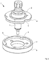
- FIG. 2 shows a solution according to the invention, which instead of the DIN 5480 toothing with a Circular teeth used by Wildhaber-Novikov.
- gearwheel 4 such a circular-arc toothing can still be added on the lathe or on a machining center by means of a milling tool, so that re-clamping and machining on the hobbing machine can be dispensed with.
- the driver element 6 the advantage is still considerably greater, since the inner contour can still be milled out as a depression here in a passage directly on the lathe or on a machining center.
- Drive plate and inner ring gear 7 are thus made uniform and integral in this solution, so that additional steps can be omitted.
- the driver element 6 further comprises on its underside a spur gear toothing of axial teeth 9, via which engagement in a counter-toothing of a second connector part can be produced.
- the driver element 6 is completely made of ferromagnetic material and the second connector part assigned an electromagnet, via which the driver element 6 is actuated, thus axially against the restoring force of a spring not shown here from the first connector part 2 away on the second also not shown here Connecting part is pulled to engage with the spur gear teeth.
- FIG. 3 shows another constructionally differently solved example with a toothed coupling, which has an outer diameter of 114 mm instead of in FIG. 2 shown variant with 80 mm. Corresponding elements are labeled the same.
- shaft-hub connector which has circular arc teeth instead of a spline made by hobbing which allows the use of a simpler, faster and cheaper manufacturing method for such shaft-hub connectors and tooth couplings made therewith.
Landscapes
- Engineering & Computer Science (AREA)
- General Engineering & Computer Science (AREA)
- Mechanical Engineering (AREA)
- Gears, Cams (AREA)
- Mechanical Operated Clutches (AREA)
- Gear Processing (AREA)
Abstract
Es sind im Stand der Technik bereits Zahnkupplungen bekannt, deren Mitnehmerelement aus einer Mitnehmerscheibe und einem Innenzahnkranz zusammengefügt wird. Dies hat den Hintergrund, dass für die Herstellung des Innenzahnkranzes, der eine Verzahnung nach DIN 5480 aufweist, im Stand der Technik ein Abwälzfräsverfahren eingesetzt wird. Allerdings erfordert dieses Vorgehen ein zweifaches Aufspannen der Teile und einen anschließenden Arbeitsschritt zur Verbindung des Innenzahnkranzes mit der Mitnehmerscheibe. Entsprechendes muss beim Gegenstück an der Welle erfolgen. Die Erfindung sieht stattdessen vor, eine Kreisbogenverzahnung auszubilden. Dies erlaubt es, die einzelnen Zahnelemente in einer einzelnen Aufspannung sowohl zunächst durch Drehen, dann durch Fräsen zu bearbeiten. Es entfällt eine zusätzliche Aufspannung und gleichzeitig der Arbeitsschritt des Zusammenfügens der Einzelteile. Im Ergebnis wird eine erheblich günstigere Herstellung der Zahn- kupplung ermöglicht.There are already known in the art toothed couplings, the entrainment is assembled from a drive plate and an inner ring gear. This has the background that a hobbing method is used in the prior art for the production of the internal gear ring, which has a toothing according to DIN 5480. However, this procedure requires a double clamping of the parts and a subsequent step for connecting the internal gear with the drive plate. The same must be done with the counterpart on the shaft. The invention instead proposes to form a circular arc toothing. This makes it possible to process the individual tooth elements in a single clamping both by turning first, then by milling. It eliminates an additional clamping and at the same time the step of assembling the items. As a result, a considerably more favorable production of the toothed coupling is made possible.
Description
Die vorliegende Erfindung betrifft einen Welle-Nabe-Verbinder, umfassend ein erstes Anschlussteil, welchem ein Mitnehmerelement axialverschieblich aber drehfest zugeordnet ist, wobei das Mitnehmerelement axiale Zahnelemente zur Ausbildung einer lösbaren Stirnverzahnung mit einem zweiten Anschlussteil, sowie radiale Zahnelemente zur Ausbildung einer axialverschieblichen Verzahnung mit dem ersten Anschlussteil aufweist, sowie eine Zahnkupplung und ein Verfahren zur Herstellung eines Welle-Nabe-Verbinders.The present invention relates to a shaft-hub connector, comprising a first connection part, which a driver element axially displaceable but rotatably associated, wherein the driver element axial tooth elements to form a detachable spur gear teeth with a second connector part, as well as radial tooth elements to form a axially displaceable gearing with the a first coupling part and a toothed coupling and a method for producing a shaft-hub connector.
Zahnkupplungen sind bereits seit Langem im Stand der Technik bekannt. Sie eignen sich besonders für Anwendungen, bei denen sie hohem Drehmoment ausgesetzt sind und sind in solchen Anwendungsgebieten besser geeignet als Reibkupplungen. Im Normalfall wird die Zahnkupplung im Stillstand eingerastet, oder aber zunächst mit der Wellengeschwindigkeit synchronisiert.Gear couplings have long been known in the art. They are particularly suitable for applications in which they are exposed to high torque and are better suited in such applications than friction clutches. Normally, the gear coupling is engaged at a standstill, or first synchronized with the shaft speed.
Eingekuppelt bieten Zahnkupplungen weitgehend drehstarre und formschlüssige Verbindungen. Dies wird durch ineinander gefügte Außen- und Innenverzahnungen gelöst, wobei der Stand der Technik insbesondere die DIN 5480-Passverzahnung einsetzt. Hierbei treffen zwei miteinander zu kuppelnde Anschlussteile zur Verbindung mit Maschinenwellen aufeinander, die über die Kupplung verbunden werden sollen. Ein erstes Anschlussteil weist hierbei ein Mitnehmerelement auf, gegenüber dem das erste Anschlussteil zwar axialverschieblich gelagert ist, aber in jeder Verschiebungsposition drehfest aufgenommen ist. Dies wird durch das Zusammenspiel einer Innenverzahnung des Mitnehmerelements mit einer Außenverzahnung an dem ersten Anschlussteil erreicht, wobei diese Verzahnung eine ausreichende Dicke aufweist, um auch bei einer gegenseitigen axialen Verschiebung noch genügend Fläche zur Kraftübertragung zu haben und damit noch genügend Drehmoment übertragen zu können.Coupled toothed couplings provide largely torsionally rigid and positive connections. This is achieved by nested outer and inner gears, the prior art in particular uses the DIN 5480-toothing. Here are two to be coupled together connecting parts for connection to machine shafts, which are to be connected via the coupling. In this case, a first connection part has a driver element, with respect to which the first connection part is mounted axially displaceably, but is held in a rotationally fixed manner in each displacement position. This is achieved by the interaction of an internal toothing of the driver element with an external toothing on the first connection part, this toothing has a sufficient thickness to have enough surface for power transmission even with a mutual axial displacement and thus still be able to transmit sufficient torque.
Soweit eine Zahnkupplung vorliegt, die stromlos öffnet, wird das Mitnehmerelement in der Ruheposition an dem ersten Anschlussteil anliegen und aufgrund einer auslösenden Kraft von diesem weg in Eingriff mit einem zweiten Anschlussteil rücken.As far as a toothed coupling is present, which opens normally, the entrainment element will abut in the rest position on the first connection part and move due to a triggering force away from this in engagement with a second connection part.
Dieser Eingriff wird über eine Stirnverzahnung hergestellt, die nur dann eingreift, wenn das Mitnehmerelement auf das zweite Anschlussteil zugerückt wurde. Auch bei einem maximalen Eingriff dieser Stirnverzahnung bleibt die Verzahnung zwischen erstem Anschlussteil und Mitnehmerelement erhalten und die beiden Wellenabschnitte, die über den ersten und den zweiten Anschlussteil mit der Zahnkupplung verbunden sind, sind eingekuppelt.This engagement is made via a spur gear, which engages only when the driver element has been moved to the second connector part. Even with a maximum engagement of these spur gearing, the gearing between the first connecting part and driving element is retained and the two shaft sections, which are connected via the first and the second connecting part with the toothed coupling, are engaged.
Eine solche Zahnkupplung arbeitet im Stand der Technik mit einem Mitnehmerelement, das aus einer Mitnehmerscheibe besteht, auf der ein Zahnkranz mit Innenverzahnung angebracht ist. Dies ist deshalb so gewählt, weil die im Stand der Technik übliche DIN 5480-Passinnenverzahnung durch Stoßen eingebracht wird, so dass eine einstückige Herstellung des Mitnehmerelements nicht möglich ist. Hierdurch ergeben sich allerdings einige Aufwendungen. Zum Einen stellt der Zusammenbau der Mitnehmerscheibe und des Innenzahnkranzes zu einem Mitnehmerelement einen zusätzlichen Arbeitsschritt dar, zum Anderen müssen die beiden Teile als Werkstücke separat hergestellt und damit separat in der Drehmaschine aufgespannt und nach der Grundbearbeitung nochmals auf der Wälzfräsmaschine aufgespannt und weiter bearbeitet werden.Such a toothed coupling operates in the prior art with a driver element, which consists of a drive plate on which a toothed ring with internal teeth is mounted. This is so chosen because the usual in the art DIN 5480-fitting internal teeth is introduced by collision, so that a one-piece production of the driver element is not possible. However, this results in some expenses. On the one hand, the assembly of the drive plate and the inner ring gear to an entrainment element is an additional step, on the other hand, the two parts must be made separately as workpieces and thus clamped separately in the lathe and after the basic machining again clamped on the hobbing machine and further processed.
Ein entsprechender Arbeitsablauf ergibt sich bei dem ersten Anschlussteil, das ebenfalls in einem Bearbeitungsschritt auf der Drehmaschine und einem anschließenden Abwälzfräsvorgang hergestellt werden muss.A corresponding workflow results in the first connection part, which also has to be produced in a processing step on the lathe and a subsequent hobbing operation.
Da diese Arbeitsvorgänge die Herstellung einer Zahnkupplung teuer machen, liegt der Erfindung die Aufgabe zu Grunde, einen Welle-Nabe-Verbinder zur Herstellung einer Zahnkupplung, eine solche Zahnkupplung und ein Herstellungsverfahren für einen Welle-Nabe-Verbinder anzugeben, welche diese zusätzlichen Kosten vermeidet und damit die Herstellungskosten und die Herstellungsdauer einer erfindungsgemäßen Zahnkupplung verringert.Since these operations make the production of a gear coupling expensive, the invention has the object to provide a shaft-hub connector for producing a gear coupling, such a gear coupling and a manufacturing method for a shaft-hub connector, which avoids these additional costs and thus reducing the manufacturing costs and the production time of a toothed coupling according to the invention.
Dies gelingt durch eine Zahnkupplung gemäß den Merkmalen des Anspruchs 1. Weitere sinnvolle Ausgestaltungen einer solchen Zahnkupplung können den Unteransprüchen 2 bis 5 entnommen werden. Ebenfalls wird diese Aufgabe durch ein Verfahren zur Herstellung einer erfindungsgemäßen Zahnkupplung gemäß den Merkmalen des nebengeordneten Anspruchs 6 gelöst.This is achieved by a toothed coupling according to the features of
Erfindungsgemäß ist zunächst ein Welle-Nabe-Verbinder vorgesehen, welcher eine Welle und eine Nabe, im vorliegenden Fall in Form eines ersten Anschlussteils zur Verbindung mit einer Welle und einem Mitnehmerelement als Na- be, umfasst. Der Welle ist ein Zahnrad zugeordnet, das radiale Gegenzahnele- mente zu den radialen Zahnelementen eines Innenzahnkranzes des Mitneh- merelements aufweist. Die Außenkontur des Zahnrads ist hierbei so gebildet, dass sie passgenau in die Innenkontur des Innenzahnkranzes des Mitnehmerelements eingepasst werden kann und somit ideale Voraussetzungen für die Kraftübertra- gung mitbringt. Hierbei ist jedoch eine Kreisbogenverzahnung realisiert, welche auch als Wildhaber-Novikov-Verzahnung bekannt ist. Derartige Verzahnungen sind bereits bei Stirnverzahnungen bekannt, im vorliegenden Fall soll eine solche Verzahnung jedoch für die Außenverzahnung des Zahnrades, bei eine radialer Ausrichtung der Zahnelemente Einsatz finden. Die einzelnen Zahnelemente haben hierbei in axialer Richtung gerade Kanten und Flächen, so dass der Innenzahnkranz des Mitnehmerelements gegenüber dem Zahnrad der Welle axialverschieblich gelagert ist.According to the invention, a shaft-hub connector is initially provided which comprises a shaft and a hub, in the present case in the form of a first connection part for connection to a shaft and a driver element as a hub. The shaft is assigned a toothed wheel which has radial counter tooth elements to the radial tooth elements of an internal gear rim of the driver element. The outer contour of the gear is in this case formed so that it can be fitted accurately into the inner contour of the inner ring gear of the driver element and thus brings ideal conditions for the power transmission. Here, however, a circular arc toothing is realized, which is also known as Wildhaber-Novikov toothing. Such teeth are already known in front teeth, but in the present case, such a toothing should be used for the external toothing of the gear, with a radial alignment of the tooth elements use. The individual tooth elements have in this case in the axial direction straight edges and surfaces, so that the inner ring gear of the driver element relative to the gear of the shaft is mounted axially displaceable.
Bei der Wildhaber-Novikov-Verzahnung greifen konvexe. halbkreisförmige Zahnelemente in korrespondierende Ausnehmungen im gegenüberliegenden Innenzahnkreis des Mitnehmerelements ein. Konstruktionsbedingt passen die Zahnelemente aufgrund dieser Konstruktion besonders gut in die Ausnehmungen, also die Gegenzahnelemente hinein, so dass bereits mit einer wesentlich geringeren Zahl an Zahnelementen gearbeitet werden kann und dennoch eine ausreichende Kraftübertragung gewährleistet werden kann.In the case of the Wildhaber-Novikov gearing, convex ones are used. semicircular tooth elements in corresponding recesses in the opposite internal toothed circle of the driver element. Due to the design, the tooth elements fit particularly well into the recesses, that is to say the counter-tooth elements, so that it is possible to work with a significantly smaller number of tooth elements and nevertheless ensure sufficient force transmission.
Der besondere Vorteil dieser Konstruktion liegt aber vor allem darin, dass die Herstellung einer solchen Kreisbogenverzahnung nicht über einen Abwälzfräsvorgang erfolgen muss, sondern ohne Weiteres etwa mit einem Fingerfräser durchgeführt werden kann. Dies ermöglicht es, das Mitnehmerelement einstückig herzustellen, weil konstruktionsbedingt auch ein Ausfräsen der Innenzahnkranz-Kontur oberflächlich erreicht werden kann, wenn dies in Form einer Kreisbogenverzahnung erfolgt. Es entfällt damit sowohl der zusätzliche Zusammenbau des Innenzahnkranzes mit einer Mitnehmerscheibe, als auch zusätzliches Aufspannen des Innenzahnkranzes auf der Wälzfräsmaschine. Es wird erhebliche Zeit und Aufwand eingespart und dennoch eine zumindest gleichwertige Lösung bereitgestellt.But the particular advantage of this design lies in the fact that the production of such a circular arc toothing does not have to take place via a hobbing process, but can easily be carried out with a milling cutter, for example. This makes it possible to produce the driver element in one piece, because by design, a milling of the internal gear rim contour can be achieved superficially, if this takes place in the form of a circular arc toothing. It thus eliminates both the additional assembly of the inner ring gear with a drive plate, as well as additional clamping of the inner ring gear on the hobbing machine. It saves considerable time and effort and yet provided an at least equivalent solution.
Auch ein Härtungsvorgang kann entfallen, weil aufgrund der geringen Verschleiße bei Kreisbogenverzahnungen ein solcher Schritt nicht notwendig ist.Also, a curing process can be omitted, because due to the low wear in circular arcs such a step is not necessary.
Ein derartiger Welle-Nabe-Verbinder kann sodann in einer Zahnkupplung wie eingangs beschrieben Verwendung finden. Hierbei kann das Mitnehmerelement auf seiner vom ersten Anschlussteil weg zeigenden Seite eine Stirnverzahnung aufweisen, mit der es in eine korrespondierende Stirnverzahnung eines zweiten Anschlussteils eingreifen kann. Durch ein axiales Verschieben des Mitnehmerteils gegenüber dem ersten Anschlussteil in Richtung des zweiten, koaxial angeordneten Anschlussteils bis zu einem Eingriff in dessen Stirnverzahnung kann ein Einkuppelvorgang bewirkt und damit eine Zahnkupplung verwirklicht werden. Das Einkuppeln erfolgt dabei in aller Regel bei einem Stillstand von Kupplung und Wellen, nach einer Drehsynchronisation, oder bei langsamen Drehzahlen mit verhältnismäßig geringen Rotationsenergien, um Beschädigungen der Stirnverzahnungen auf beiden Seiten zu verhindern.Such a shaft-hub connector can then be used in a gear coupling as described above. Here, the driver element on its side facing away from the first connector part side have a spur gear, with which it can engage in a corresponding spur toothing of a second connector part. By an axial displacement of the driver part relative to the first connection part in the direction of the second, coaxially arranged connection part up to an engagement in the spur toothing of a coupling process can be effected and thus a toothed coupling can be realized. The coupling takes place usually at a standstill of the clutch and shafts, after a rotary synchronization, or at slow speeds with relatively low rotational energy to prevent damage to the serrations on both sides.
In einer derartigen Zahnkupplung kann das Mitnehmerelement gegenüber dem ersten Anschlussteil in einer Ruheposition gehalten werden, indem es eine Rückstellkraft erfährt, beispielsweise mithilfe einer Feder gegen das erste Anschlussteil gedrückt wird. Damit wäre die stromlos-offen-Variante beschrieben. Drückt eine solche Feder hingegen in die andere Richtung, also das Mitnehmerelement in Kontakt mit dem zweiten Anschlussteil und dessen Stirnverzahnung, so würde es sich um eine stromlosgeschlossen-Variante handeln. Beide Varianten sind ohne weiteres möglich. Durch eine Gegenkraft wird die Rückstellkraft überwunden und die Verbindung geschlossen bzw. geöffnet.In such a toothed coupling, the driver element can be held in a rest position relative to the first connector part by experiencing a restoring force, for example, by pressing against the first connector part by means of a spring. This would describe the normally open variant. On the other hand, if such a spring pushes in the other direction, that is to say the driver element in contact with the second connection part and its spur toothing, then this would be a normally closed variant. Both variants are possible without further ado. By an opposing force, the restoring force is overcome and the connection is closed or opened.
Während der Verschiebung des Mitnehmerelement zwischen einer Ruheposition und einer Betätigungsposition gerät die Stirnverzahnung des Mitnehmerelements zwar in bzw. außer Eingriff der Stirnverzahnung des zweiten Anschlussteils, jedoch bleibt die Innenverzahnung des Mitnehmerelements hierbei stets im Eingriff der Außenverzahnung des ersten Anschlussteils, so dass hier immer eine weitere Mitnahme erfolgt.While the displacement of the driver element between a rest position and an actuation position, the front teeth of the driver element indeed in or out of engagement of the spur toothing of the second connection part, but the internal teeth of the driver element always remains engaged by the external teeth of the first connector, so that here is always another Carrying takes place.
Als Gegenkraft zur Überwindung der Rückstellkraft eignet sich beispielsweise eine elektromagnetische Kraft, die über einen Elektromagneten erzeugt werden kann. Ein solcher Elektromagnet kann in das zweite Anschlussteil eingebaut oder diesem zugeordnet sein und auf das Mitnehmerelement einwirken. Hierzu muss in diesem Fall das Mitnehmerelement entweder ganz aus einem ferromagnetischen Material hergestellt sein oder aber ein ferromagnetisches oder permanentmagnetisches Element umfassen, welches auf die elektromagnetische Anziehungskraft reagiert. Durch die Einwirkung des Elektromagneten auf ein solches ferromagnetisches Mitnehmerelement kann dieses aus der Ruheposition in die eingekuppelte Position verschoben werden, so dass die Kupplung über den Elektromagneten schaltbar ist.As an opposing force to overcome the restoring force is, for example, an electromagnetic force that can be generated by an electromagnet. One Such electromagnet can be installed in the second connection part or assigned to this and act on the driver element. For this purpose, in this case, the driver element must either be made entirely of a ferromagnetic material or comprise a ferromagnetic or permanent magnetic element which responds to the electromagnetic attraction. By the action of the electromagnet on such a ferromagnetic carrier element, this can be moved from the rest position to the engaged position, so that the coupling is switchable via the electromagnet.
In bevorzugter Ausgestaltung weist der Innenzahnkranz des Mitnehmerelements zwei bis sieben, besonders bevorzugt drei, radiale Zahnelemente auf. Eine überschaubare Anzahl an radialen Zahnelementen in einer ausreichenden Größe erlaubt es, unproblematisch die Innenkontur des Mitnehmerelements mit dem Fräswerkzeug zu bearbeiten. Ebenfalls sind die radialen Zahnelemente und damit auch die korrespondierenden radialen Gegenzahnelemente zumindest weitestgehend auf dem Umfang des Innenzahnkranzes gleichmäßig verteilt, so dass die Kraftverteilung im dem Mitnehmerelement ihrerseits gleichmäßig ist und möglichst wenig Lastspitzen an einzelnen Stellen auftreten.In a preferred embodiment, the inner ring gear of the driver element on two to seven, more preferably three, radial tooth elements. A manageable number of radial tooth elements in a sufficient size allows to easily edit the inner contour of the driver element with the milling tool. Likewise, the radial tooth elements and thus also the corresponding radial counter-tooth elements are at least largely evenly distributed on the circumference of the internal ring gear, so that the force distribution in the driver element in turn is uniform and as few load peaks occur at individual points.
Im Zuge der Herstellung des eingangs beschriebenen Welle-Nabe-Verbinders wird das erste Anschlussteil ebenso wie das Mitnehmerelement jeweils auf einer Drehmaschine gefertigt. Beide Teile können dann in derselben Aufspannung mit dem Fräser bearbeitet werden, so dass ein Umspannen der Werkstücke entfallen kann. Mit einem Fingerfräser können dabei die Konturen ausreichend fein herausgearbeitet werden. Neben dem Umspannen in die Wälzfräsmaschine kann hierdurch auch das Zusammenbauen der im Stand der Technik noch benötigten Mit- nehmerscheibe mit dem separaten Innenzahnkranz entfallen und somit die Her- stelldauer merklich reduziert werden.In the course of the production of the shaft-hub connector described above, the first connection part as well as the driver element are each manufactured on a lathe. Both parts can then be processed in the same clamping with the cutter, so that a re-clamping of the workpieces can be omitted. With a finger milling cutter, the contours can be worked out sufficiently fine. In addition to the clamping into the hobbing machine, this also eliminates the need to assemble the driver disk still required in the prior art with the separate internal ring gear and thus significantly reduce the manufacturing time.
Die vorstehend beschriebene Erfindung wird im Folgenden anhand eines Ausführungsbeispiels näher erläutert.The invention described above will be explained in more detail below with reference to an embodiment.
Es zeigen
Figur 1- ein Welle-Nabe-Verbinder für eine Zahnkupplung gemäß dem Stand der Technik in einer perspektivischen Explosionsdarstellung von schräg oben,
Figur 2- ein erfindungsgemäßer Welle-Nabe-Verbinder für eine Zahnkupplung in einer perspektivischen Explosionsdar- stellung von schräg oben, sowie
Figur 3- eine alternative Ausgestaltung eines Welle-Nabe-Verbinders für eine Zahnkupplung in einer perspektivischen Explosionsdarstellung von schräg oben.
- FIG. 1
- a shaft-hub connector for a toothed coupling according to the prior art in an exploded perspective view obliquely from above
- FIG. 2
- an inventive shaft-hub connector for a gear coupling in a perspective exploded view obliquely from above, and
- FIG. 3
- an alternative embodiment of a shaft-hub connector for a gear coupling in a perspective exploded view obliquely from above.
Der Stand der Technik kennt hierbei die hier dargestellte DIN 5480-Verzahnung, die aus einer Vielzahl einzelner Zähne besteht, wobei die Außenverzahnung durch Abwälzfräsen und die Innenverzahnung des Gegenstücks durch Stoßen herge- stellt werden müssen. Hierbei wird der Innenzahnkranz 7 vollständig vom Stoßwerkzeug durchgriffen, so dass in einem nachgelagerten Arbeitsschritt eine Mitnehmerscheibe 10 mit dem Innenzahnkranz 7 zu einem Mitnehmerelement 6 ver- bunden werden müssen. Hierzu wird ein Teil des Innenzahnkranzes 7 mit einem weiteren Innendurchmesser hergestellt, in den die Mitnehmerscheibe 10 eingelegt werden kann. Dieser Teil wird dann von Verbindungsstiften 11 durchgriffen, mit deren Hilfe in diesem zusätzlichen Arbeitsschritt die Verbindung zwischen Innenzahnkranz 7 und Mitnehmerscheibe 10 hergestellt wird.The state of the art here knows the DIN 5480 toothing shown here, which consists of a plurality of individual teeth, wherein the external toothing must be produced by hobbing and the internal toothing of the counterpart by impact. In this case, the
Im Gegensatz hierzu sieht die Erfindung eine deutliche Vereinfachung vor.
Für den Fall einer Verwendung dieses Welle-Nabe-Verbinders 1 in einer Zahnkupplung weist das Mitnehmerelement 6 ferner an seiner Unterseite eine Stirnverzahnung aus axialen Zahnelementen 9 auf, über die ein Eingriff in eine Gegenverzahnung eines zweiten Anschlussteils hergestellt werden kann. In diesem Fall wird das Mitnehmerelement 6 vollständig aus ferromagnetischem Material hergestellt und dem zweiten Anschlussteil ein Elektromagnet zugeordnet, über welchen das Mitnehmerelement 6 betätigt, mithin gegen die Rückstellkraft einer hier nicht gezeigten Feder von dem ersten Anschlussteil 2 weg axial auf das hier ebenfalls nicht gezeigte zweite Anschlussteil zu gezogen wird, um mit der Stirnverzahnung in Eingriff zu gelangen. Der hierbei auftretende Hub ist jedoch nur so groß, dass die radialen Gegenzahnelemente 5 des ersten Anschlussteils 2 weiterhin in Eingriff mit den radialen Zahnelementen 8 des Mitnehmerelements 6 verbleiben und somit die hier nicht gezeigten zu verbindenden Wellenabschnitte miteinander in Kraftschluss gelangen.In the case of a use of this shaft-
Vorstehend beschrieben ist somit ein Welle-Nabe-Verbinder, der anstelle einer durch Abwälzfräsen hergestellten Passverzahnung eine Kreisbogenverzahnung aufweist, was die Anwendung eines einfacheren, schnelleren und kostengünstigeren Herstellungsverfahrens für derartige Welle-Nabe-Verbinder und damit hergestellte Zahnkupplungen ermöglicht.Thus, described above is a shaft-hub connector which has circular arc teeth instead of a spline made by hobbing which allows the use of a simpler, faster and cheaper manufacturing method for such shaft-hub connectors and tooth couplings made therewith.
- 11
- Welle-Nabe-VerbinderShaft-hub-connector
- 22
- erstes Anschlussteilfirst connection part
- 33
- Wellewave
- 44
- Zahnradgear
- 55
- radiale Gegenzahnelementeradial counter-tooth elements
- 66
- Mitnehmerelementdogging
- 77
- InnenzahnkranzInternal ring gear
- 88th
- radiale ZahnelementeRadial tooth elements
- 99
- axiale Zahnelementeaxial tooth elements
- 1010
- Mitnehmerscheibedriver disc
- 1111
- Verbindungsstiftconnecting pin
Claims (7)
Applications Claiming Priority (1)
| Application Number | Priority Date | Filing Date | Title |
|---|---|---|---|
| DE102016124092.3A DE102016124092A1 (en) | 2016-12-12 | 2016-12-12 | Shaft-hub connector, gear coupling and manufacturing method for a shaft-hub connection |
Publications (3)
| Publication Number | Publication Date |
|---|---|
| EP3354917A2 true EP3354917A2 (en) | 2018-08-01 |
| EP3354917A3 EP3354917A3 (en) | 2018-09-12 |
| EP3354917B1 EP3354917B1 (en) | 2020-02-05 |
Family
ID=60654880
Family Applications (1)
| Application Number | Title | Priority Date | Filing Date |
|---|---|---|---|
| EP17206533.6A Active EP3354917B1 (en) | 2016-12-12 | 2017-12-11 | Shaft hub connector and manufacturing method for a shaft hub connector |
Country Status (4)
| Country | Link |
|---|---|
| EP (1) | EP3354917B1 (en) |
| CN (1) | CN108223596B (en) |
| DE (1) | DE102016124092A1 (en) |
| ES (1) | ES2773791T3 (en) |
Families Citing this family (1)
| Publication number | Priority date | Publication date | Assignee | Title |
|---|---|---|---|---|
| US11834798B2 (en) | 2021-10-06 | 2023-12-05 | Caterpillar Paving Products Inc. | System for transferring torque from driveshafts to milling drums |
Family Cites Families (5)
| Publication number | Priority date | Publication date | Assignee | Title |
|---|---|---|---|---|
| US3584667A (en) * | 1966-09-19 | 1971-06-15 | Textron Inc | Coupling arrangement and tools for same |
| US4622840A (en) * | 1983-06-20 | 1986-11-18 | Neapco, Inc. | Method for drawing telescoping tubes for torque transmission |
| DE3635916C1 (en) * | 1986-10-22 | 1988-03-24 | Voith Gmbh J M | Gearing for a shaft-hub connection |
| DE102013217035A1 (en) * | 2013-08-27 | 2015-03-05 | Volkswagen Aktiengesellschaft | Method for centering a centering part and rotation component |
| TR201505304A2 (en) * | 2015-04-30 | 2015-07-21 | Valeo Otomotiv Sanayi Ve Ticaret A S | A POWER TRANSMISSION ARRANGEMENT WITH DRIVE PLATE |
-
2016
- 2016-12-12 DE DE102016124092.3A patent/DE102016124092A1/en not_active Ceased
-
2017
- 2017-12-11 CN CN201711308852.7A patent/CN108223596B/en active Active
- 2017-12-11 EP EP17206533.6A patent/EP3354917B1/en active Active
- 2017-12-11 ES ES17206533T patent/ES2773791T3/en active Active
Non-Patent Citations (1)
| Title |
|---|
| None |
Also Published As
| Publication number | Publication date |
|---|---|
| CN108223596B (en) | 2021-12-07 |
| DE102016124092A1 (en) | 2018-06-14 |
| EP3354917B1 (en) | 2020-02-05 |
| EP3354917A3 (en) | 2018-09-12 |
| CN108223596A (en) | 2018-06-29 |
| ES2773791T3 (en) | 2020-07-14 |
Similar Documents
| Publication | Publication Date | Title |
|---|---|---|
| EP0717212B1 (en) | Synchronising device for gearbox | |
| DE4240131C2 (en) | Connection between inner joint part and drive shaft | |
| DE2261446A1 (en) | TOOTHED FORCE-TRANSMITTING COMPONENT AND METHOD FOR MANUFACTURING IT | |
| DE10220372A1 (en) | Polygonal interface between driving and driven components | |
| EP2913561A1 (en) | Motor planetary drive assembly and method of connecting a motor with a planetary drive to produce a motor planetary drive assembly | |
| EP1945957B1 (en) | Mechanism for securing a shaft-hub connection of two shafts | |
| EP2222975A1 (en) | Coupling element for transmitting torque and drive unit comprising said coupling element | |
| WO2022083982A1 (en) | Eccentric gear unit for a braking force generator, and braking force generator | |
| EP3354917B1 (en) | Shaft hub connector and manufacturing method for a shaft hub connector | |
| DE102012202446A1 (en) | Pinion i.e. sun wheel, for differential gear box that is utilized as spur gear differential gear box of motor car, has locking unit introduced in case and as internal thread in recess of wheel body for axially locking shaft | |
| DE102006023098B3 (en) | Synchronizing unit for a gear box comprises a spring arrangement between an inner synchronous ring and an outer synchronous ring to press the rings in the axial direction of a drives shaft | |
| DE102011102288B4 (en) | Device and method for producing a spur gear with a helical toothing | |
| DE102010036277B4 (en) | Coupling body for a gear wheel of a manual transmission and gear wheel with coupling body | |
| DE19915027A1 (en) | Forming gear element for starter motor, and resultant gear element, with successively diminishing wall thickness of element obtained by combined radial and axial motion of at least one adjustable roll of pressure rolling machine | |
| EP3620677A1 (en) | Multi-disc clutch | |
| DE102015121705A1 (en) | Coupling arrangement, in particular for optionally connecting an air compressor with a drive device | |
| DE102011119574B4 (en) | Method for producing a coupling body | |
| DE10214910A1 (en) | Method for forming a spring engagement part of a link with an axial hole and a spring engagement part structure | |
| DE102012205727A1 (en) | Hub universal joint assembly | |
| DE102015108991A1 (en) | Hub, sliding sleeve and synchronization device and method for producing a hub and method for producing a sliding sleeve | |
| EP2478244B1 (en) | Selector sleeve for a manual transmission | |
| DE102014210631A1 (en) | Sheet metal cylinder with driving profile and method of manufacture | |
| EP3869057B1 (en) | Gear wheel unit and method of manufacturing a clutch disc for a gear wheel unit | |
| DE102018120171A1 (en) | Ball screw drive and method for producing a ball screw drive | |
| WO2018137954A1 (en) | Assembly of an axle or a shaft on a component, in particular for a vehicle, and vehicle comprising such an assembly |
Legal Events
| Date | Code | Title | Description |
|---|---|---|---|
| PUAI | Public reference made under article 153(3) epc to a published international application that has entered the european phase |
Free format text: ORIGINAL CODE: 0009012 |
|
| STAA | Information on the status of an ep patent application or granted ep patent |
Free format text: STATUS: THE APPLICATION HAS BEEN PUBLISHED |
|
| AK | Designated contracting states |
Kind code of ref document: A2 Designated state(s): AL AT BE BG CH CY CZ DE DK EE ES FI FR GB GR HR HU IE IS IT LI LT LU LV MC MK MT NL NO PL PT RO RS SE SI SK SM TR |
|
| AX | Request for extension of the european patent |
Extension state: BA ME |
|
| PUAL | Search report despatched |
Free format text: ORIGINAL CODE: 0009013 |
|
| AK | Designated contracting states |
Kind code of ref document: A3 Designated state(s): AL AT BE BG CH CY CZ DE DK EE ES FI FR GB GR HR HU IE IS IT LI LT LU LV MC MK MT NL NO PL PT RO RS SE SI SK SM TR |
|
| AX | Request for extension of the european patent |
Extension state: BA ME |
|
| RIC1 | Information provided on ipc code assigned before grant |
Ipc: F16D 1/06 20060101AFI20180806BHEP Ipc: F16D 27/00 20060101ALI20180806BHEP Ipc: B23F 17/00 20060101ALI20180806BHEP Ipc: F16D 1/108 20060101ALI20180806BHEP Ipc: F16D 1/10 20060101ALI20180806BHEP |
|
| STAA | Information on the status of an ep patent application or granted ep patent |
Free format text: STATUS: REQUEST FOR EXAMINATION WAS MADE |
|
| 17P | Request for examination filed |
Effective date: 20190312 |
|
| RBV | Designated contracting states (corrected) |
Designated state(s): AL AT BE BG CH CY CZ DE DK EE ES FI FR GB GR HR HU IE IS IT LI LT LU LV MC MK MT NL NO PL PT RO RS SE SI SK SM TR |
|
| GRAP | Despatch of communication of intention to grant a patent |
Free format text: ORIGINAL CODE: EPIDOSNIGR1 |
|
| STAA | Information on the status of an ep patent application or granted ep patent |
Free format text: STATUS: GRANT OF PATENT IS INTENDED |
|
| INTG | Intention to grant announced |
Effective date: 20190711 |
|
| RIC1 | Information provided on ipc code assigned before grant |
Ipc: B23F 17/00 20060101ALI20190628BHEP Ipc: F16D 1/104 20060101ALI20190628BHEP Ipc: F16D 1/06 20060101AFI20190628BHEP Ipc: F16D 1/10 20060101ALI20190628BHEP Ipc: F16D 27/00 20060101ALI20190628BHEP |
|
| GRAS | Grant fee paid |
Free format text: ORIGINAL CODE: EPIDOSNIGR3 |
|
| GRAA | (expected) grant |
Free format text: ORIGINAL CODE: 0009210 |
|
| STAA | Information on the status of an ep patent application or granted ep patent |
Free format text: STATUS: THE PATENT HAS BEEN GRANTED |
|
| AK | Designated contracting states |
Kind code of ref document: B1 Designated state(s): AL AT BE BG CH CY CZ DE DK EE ES FI FR GB GR HR HU IE IS IT LI LT LU LV MC MK MT NL NO PL PT RO RS SE SI SK SM TR |
|
| REG | Reference to a national code |
Ref country code: GB Ref legal event code: FG4D Free format text: NOT ENGLISH |
|
| REG | Reference to a national code |
Ref country code: AT Ref legal event code: REF Ref document number: 1230127 Country of ref document: AT Kind code of ref document: T Effective date: 20200215 |
|
| REG | Reference to a national code |
Ref country code: DE Ref legal event code: R096 Ref document number: 502017003694 Country of ref document: DE |
|
| REG | Reference to a national code |
Ref country code: IE Ref legal event code: FG4D Free format text: LANGUAGE OF EP DOCUMENT: GERMAN |
|
| REG | Reference to a national code |
Ref country code: CH Ref legal event code: EP |
|
| REG | Reference to a national code |
Ref country code: NL Ref legal event code: MP Effective date: 20200205 |
|
| REG | Reference to a national code |
Ref country code: ES Ref legal event code: FG2A Ref document number: 2773791 Country of ref document: ES Kind code of ref document: T3 Effective date: 20200714 |
|
| PG25 | Lapsed in a contracting state [announced via postgrant information from national office to epo] |
Ref country code: NO Free format text: LAPSE BECAUSE OF FAILURE TO SUBMIT A TRANSLATION OF THE DESCRIPTION OR TO PAY THE FEE WITHIN THE PRESCRIBED TIME-LIMIT Effective date: 20200505 Ref country code: PT Free format text: LAPSE BECAUSE OF FAILURE TO SUBMIT A TRANSLATION OF THE DESCRIPTION OR TO PAY THE FEE WITHIN THE PRESCRIBED TIME-LIMIT Effective date: 20200628 Ref country code: FI Free format text: LAPSE BECAUSE OF FAILURE TO SUBMIT A TRANSLATION OF THE DESCRIPTION OR TO PAY THE FEE WITHIN THE PRESCRIBED TIME-LIMIT Effective date: 20200205 Ref country code: RS Free format text: LAPSE BECAUSE OF FAILURE TO SUBMIT A TRANSLATION OF THE DESCRIPTION OR TO PAY THE FEE WITHIN THE PRESCRIBED TIME-LIMIT Effective date: 20200205 |
|
| REG | Reference to a national code |
Ref country code: LT Ref legal event code: MG4D |
|
| PG25 | Lapsed in a contracting state [announced via postgrant information from national office to epo] |
Ref country code: HR Free format text: LAPSE BECAUSE OF FAILURE TO SUBMIT A TRANSLATION OF THE DESCRIPTION OR TO PAY THE FEE WITHIN THE PRESCRIBED TIME-LIMIT Effective date: 20200205 Ref country code: IS Free format text: LAPSE BECAUSE OF FAILURE TO SUBMIT A TRANSLATION OF THE DESCRIPTION OR TO PAY THE FEE WITHIN THE PRESCRIBED TIME-LIMIT Effective date: 20200605 Ref country code: GR Free format text: LAPSE BECAUSE OF FAILURE TO SUBMIT A TRANSLATION OF THE DESCRIPTION OR TO PAY THE FEE WITHIN THE PRESCRIBED TIME-LIMIT Effective date: 20200506 Ref country code: BG Free format text: LAPSE BECAUSE OF FAILURE TO SUBMIT A TRANSLATION OF THE DESCRIPTION OR TO PAY THE FEE WITHIN THE PRESCRIBED TIME-LIMIT Effective date: 20200505 Ref country code: SE Free format text: LAPSE BECAUSE OF FAILURE TO SUBMIT A TRANSLATION OF THE DESCRIPTION OR TO PAY THE FEE WITHIN THE PRESCRIBED TIME-LIMIT Effective date: 20200205 Ref country code: LV Free format text: LAPSE BECAUSE OF FAILURE TO SUBMIT A TRANSLATION OF THE DESCRIPTION OR TO PAY THE FEE WITHIN THE PRESCRIBED TIME-LIMIT Effective date: 20200205 |
|
| PG25 | Lapsed in a contracting state [announced via postgrant information from national office to epo] |
Ref country code: NL Free format text: LAPSE BECAUSE OF FAILURE TO SUBMIT A TRANSLATION OF THE DESCRIPTION OR TO PAY THE FEE WITHIN THE PRESCRIBED TIME-LIMIT Effective date: 20200205 |
|
| PG25 | Lapsed in a contracting state [announced via postgrant information from national office to epo] |
Ref country code: RO Free format text: LAPSE BECAUSE OF FAILURE TO SUBMIT A TRANSLATION OF THE DESCRIPTION OR TO PAY THE FEE WITHIN THE PRESCRIBED TIME-LIMIT Effective date: 20200205 Ref country code: LT Free format text: LAPSE BECAUSE OF FAILURE TO SUBMIT A TRANSLATION OF THE DESCRIPTION OR TO PAY THE FEE WITHIN THE PRESCRIBED TIME-LIMIT Effective date: 20200205 Ref country code: CZ Free format text: LAPSE BECAUSE OF FAILURE TO SUBMIT A TRANSLATION OF THE DESCRIPTION OR TO PAY THE FEE WITHIN THE PRESCRIBED TIME-LIMIT Effective date: 20200205 Ref country code: SK Free format text: LAPSE BECAUSE OF FAILURE TO SUBMIT A TRANSLATION OF THE DESCRIPTION OR TO PAY THE FEE WITHIN THE PRESCRIBED TIME-LIMIT Effective date: 20200205 Ref country code: DK Free format text: LAPSE BECAUSE OF FAILURE TO SUBMIT A TRANSLATION OF THE DESCRIPTION OR TO PAY THE FEE WITHIN THE PRESCRIBED TIME-LIMIT Effective date: 20200205 Ref country code: EE Free format text: LAPSE BECAUSE OF FAILURE TO SUBMIT A TRANSLATION OF THE DESCRIPTION OR TO PAY THE FEE WITHIN THE PRESCRIBED TIME-LIMIT Effective date: 20200205 Ref country code: SM Free format text: LAPSE BECAUSE OF FAILURE TO SUBMIT A TRANSLATION OF THE DESCRIPTION OR TO PAY THE FEE WITHIN THE PRESCRIBED TIME-LIMIT Effective date: 20200205 |
|
| REG | Reference to a national code |
Ref country code: DE Ref legal event code: R097 Ref document number: 502017003694 Country of ref document: DE |
|
| PLBE | No opposition filed within time limit |
Free format text: ORIGINAL CODE: 0009261 |
|
| STAA | Information on the status of an ep patent application or granted ep patent |
Free format text: STATUS: NO OPPOSITION FILED WITHIN TIME LIMIT |
|
| 26N | No opposition filed |
Effective date: 20201106 |
|
| PG25 | Lapsed in a contracting state [announced via postgrant information from national office to epo] |
Ref country code: IT Free format text: LAPSE BECAUSE OF FAILURE TO SUBMIT A TRANSLATION OF THE DESCRIPTION OR TO PAY THE FEE WITHIN THE PRESCRIBED TIME-LIMIT Effective date: 20200205 |
|
| PG25 | Lapsed in a contracting state [announced via postgrant information from national office to epo] |
Ref country code: SI Free format text: LAPSE BECAUSE OF FAILURE TO SUBMIT A TRANSLATION OF THE DESCRIPTION OR TO PAY THE FEE WITHIN THE PRESCRIBED TIME-LIMIT Effective date: 20200205 Ref country code: PL Free format text: LAPSE BECAUSE OF FAILURE TO SUBMIT A TRANSLATION OF THE DESCRIPTION OR TO PAY THE FEE WITHIN THE PRESCRIBED TIME-LIMIT Effective date: 20200205 |
|
| REG | Reference to a national code |
Ref country code: CH Ref legal event code: PL |
|
| PG25 | Lapsed in a contracting state [announced via postgrant information from national office to epo] |
Ref country code: MC Free format text: LAPSE BECAUSE OF FAILURE TO SUBMIT A TRANSLATION OF THE DESCRIPTION OR TO PAY THE FEE WITHIN THE PRESCRIBED TIME-LIMIT Effective date: 20200205 |
|
| REG | Reference to a national code |
Ref country code: BE Ref legal event code: MM Effective date: 20201231 |
|
| PG25 | Lapsed in a contracting state [announced via postgrant information from national office to epo] |
Ref country code: IE Free format text: LAPSE BECAUSE OF NON-PAYMENT OF DUE FEES Effective date: 20201211 Ref country code: LU Free format text: LAPSE BECAUSE OF NON-PAYMENT OF DUE FEES Effective date: 20201211 |
|
| PG25 | Lapsed in a contracting state [announced via postgrant information from national office to epo] |
Ref country code: CH Free format text: LAPSE BECAUSE OF NON-PAYMENT OF DUE FEES Effective date: 20201231 Ref country code: LI Free format text: LAPSE BECAUSE OF NON-PAYMENT OF DUE FEES Effective date: 20201231 |
|
| PG25 | Lapsed in a contracting state [announced via postgrant information from national office to epo] |
Ref country code: TR Free format text: LAPSE BECAUSE OF FAILURE TO SUBMIT A TRANSLATION OF THE DESCRIPTION OR TO PAY THE FEE WITHIN THE PRESCRIBED TIME-LIMIT Effective date: 20200205 Ref country code: MT Free format text: LAPSE BECAUSE OF FAILURE TO SUBMIT A TRANSLATION OF THE DESCRIPTION OR TO PAY THE FEE WITHIN THE PRESCRIBED TIME-LIMIT Effective date: 20200205 Ref country code: CY Free format text: LAPSE BECAUSE OF FAILURE TO SUBMIT A TRANSLATION OF THE DESCRIPTION OR TO PAY THE FEE WITHIN THE PRESCRIBED TIME-LIMIT Effective date: 20200205 |
|
| PG25 | Lapsed in a contracting state [announced via postgrant information from national office to epo] |
Ref country code: MK Free format text: LAPSE BECAUSE OF FAILURE TO SUBMIT A TRANSLATION OF THE DESCRIPTION OR TO PAY THE FEE WITHIN THE PRESCRIBED TIME-LIMIT Effective date: 20200205 Ref country code: AL Free format text: LAPSE BECAUSE OF FAILURE TO SUBMIT A TRANSLATION OF THE DESCRIPTION OR TO PAY THE FEE WITHIN THE PRESCRIBED TIME-LIMIT Effective date: 20200205 |
|
| PG25 | Lapsed in a contracting state [announced via postgrant information from national office to epo] |
Ref country code: BE Free format text: LAPSE BECAUSE OF NON-PAYMENT OF DUE FEES Effective date: 20201231 |
|
| PGFP | Annual fee paid to national office [announced via postgrant information from national office to epo] |
Ref country code: GB Payment date: 20231220 Year of fee payment: 7 |
|
| PGFP | Annual fee paid to national office [announced via postgrant information from national office to epo] |
Ref country code: FR Payment date: 20231222 Year of fee payment: 7 Ref country code: DE Payment date: 20231214 Year of fee payment: 7 |
|
| REG | Reference to a national code |
Ref country code: AT Ref legal event code: MM01 Ref document number: 1230127 Country of ref document: AT Kind code of ref document: T Effective date: 20221211 |
|
| PGFP | Annual fee paid to national office [announced via postgrant information from national office to epo] |
Ref country code: ES Payment date: 20240129 Year of fee payment: 7 |
|
| PG25 | Lapsed in a contracting state [announced via postgrant information from national office to epo] |
Ref country code: AT Free format text: LAPSE BECAUSE OF NON-PAYMENT OF DUE FEES Effective date: 20221211 |
|
| PG25 | Lapsed in a contracting state [announced via postgrant information from national office to epo] |
Ref country code: AT Free format text: LAPSE BECAUSE OF NON-PAYMENT OF DUE FEES Effective date: 20221211 |