EP3354915A1 - Connecting rod module and production method therefor - Google Patents
Connecting rod module and production method therefor Download PDFInfo
- Publication number
- EP3354915A1 EP3354915A1 EP16848462.4A EP16848462A EP3354915A1 EP 3354915 A1 EP3354915 A1 EP 3354915A1 EP 16848462 A EP16848462 A EP 16848462A EP 3354915 A1 EP3354915 A1 EP 3354915A1
- Authority
- EP
- European Patent Office
- Prior art keywords
- connecting rod
- end portion
- hole
- gpa
- bearing raceway
- Prior art date
- Legal status (The legal status is an assumption and is not a legal conclusion. Google has not performed a legal analysis and makes no representation as to the accuracy of the status listed.)
- Granted
Links
Images


Classifications
-
- F—MECHANICAL ENGINEERING; LIGHTING; HEATING; WEAPONS; BLASTING
- F16—ENGINEERING ELEMENTS AND UNITS; GENERAL MEASURES FOR PRODUCING AND MAINTAINING EFFECTIVE FUNCTIONING OF MACHINES OR INSTALLATIONS; THERMAL INSULATION IN GENERAL
- F16C—SHAFTS; FLEXIBLE SHAFTS; ELEMENTS OR CRANKSHAFT MECHANISMS; ROTARY BODIES OTHER THAN GEARING ELEMENTS; BEARINGS
- F16C7/00—Connecting-rods or like links pivoted at both ends; Construction of connecting-rod heads
- F16C7/02—Constructions of connecting-rods with constant length
-
- B—PERFORMING OPERATIONS; TRANSPORTING
- B22—CASTING; POWDER METALLURGY
- B22F—WORKING METALLIC POWDER; MANUFACTURE OF ARTICLES FROM METALLIC POWDER; MAKING METALLIC POWDER; APPARATUS OR DEVICES SPECIALLY ADAPTED FOR METALLIC POWDER
- B22F7/00—Manufacture of composite layers, workpieces, or articles, comprising metallic powder, by sintering the powder, with or without compacting wherein at least one part is obtained by sintering or compression
- B22F7/06—Manufacture of composite layers, workpieces, or articles, comprising metallic powder, by sintering the powder, with or without compacting wherein at least one part is obtained by sintering or compression of composite workpieces or articles from parts, e.g. to form tipped tools
- B22F7/08—Manufacture of composite layers, workpieces, or articles, comprising metallic powder, by sintering the powder, with or without compacting wherein at least one part is obtained by sintering or compression of composite workpieces or articles from parts, e.g. to form tipped tools with one or more parts not made from powder
-
- F—MECHANICAL ENGINEERING; LIGHTING; HEATING; WEAPONS; BLASTING
- F16—ENGINEERING ELEMENTS AND UNITS; GENERAL MEASURES FOR PRODUCING AND MAINTAINING EFFECTIVE FUNCTIONING OF MACHINES OR INSTALLATIONS; THERMAL INSULATION IN GENERAL
- F16C—SHAFTS; FLEXIBLE SHAFTS; ELEMENTS OR CRANKSHAFT MECHANISMS; ROTARY BODIES OTHER THAN GEARING ELEMENTS; BEARINGS
- F16C19/00—Bearings with rolling contact, for exclusively rotary movement
- F16C19/22—Bearings with rolling contact, for exclusively rotary movement with bearing rollers essentially of the same size in one or more circular rows, e.g. needle bearings
- F16C19/44—Needle bearings
- F16C19/46—Needle bearings with one row or needles
- F16C19/466—Needle bearings with one row or needles comprising needle rollers and an outer ring, i.e. subunit without inner ring
-
- F—MECHANICAL ENGINEERING; LIGHTING; HEATING; WEAPONS; BLASTING
- F16—ENGINEERING ELEMENTS AND UNITS; GENERAL MEASURES FOR PRODUCING AND MAINTAINING EFFECTIVE FUNCTIONING OF MACHINES OR INSTALLATIONS; THERMAL INSULATION IN GENERAL
- F16C—SHAFTS; FLEXIBLE SHAFTS; ELEMENTS OR CRANKSHAFT MECHANISMS; ROTARY BODIES OTHER THAN GEARING ELEMENTS; BEARINGS
- F16C35/00—Rigid support of bearing units; Housings, e.g. caps, covers
- F16C35/04—Rigid support of bearing units; Housings, e.g. caps, covers in the case of ball or roller bearings
- F16C35/06—Mounting or dismounting of ball or roller bearings; Fixing them onto shaft or in housing
- F16C35/067—Fixing them in a housing
-
- F—MECHANICAL ENGINEERING; LIGHTING; HEATING; WEAPONS; BLASTING
- F16—ENGINEERING ELEMENTS AND UNITS; GENERAL MEASURES FOR PRODUCING AND MAINTAINING EFFECTIVE FUNCTIONING OF MACHINES OR INSTALLATIONS; THERMAL INSULATION IN GENERAL
- F16C—SHAFTS; FLEXIBLE SHAFTS; ELEMENTS OR CRANKSHAFT MECHANISMS; ROTARY BODIES OTHER THAN GEARING ELEMENTS; BEARINGS
- F16C7/00—Connecting-rods or like links pivoted at both ends; Construction of connecting-rod heads
- F16C7/02—Constructions of connecting-rods with constant length
- F16C7/023—Constructions of connecting-rods with constant length for piston engines, pumps or the like
-
- F—MECHANICAL ENGINEERING; LIGHTING; HEATING; WEAPONS; BLASTING
- F16—ENGINEERING ELEMENTS AND UNITS; GENERAL MEASURES FOR PRODUCING AND MAINTAINING EFFECTIVE FUNCTIONING OF MACHINES OR INSTALLATIONS; THERMAL INSULATION IN GENERAL
- F16C—SHAFTS; FLEXIBLE SHAFTS; ELEMENTS OR CRANKSHAFT MECHANISMS; ROTARY BODIES OTHER THAN GEARING ELEMENTS; BEARINGS
- F16C9/00—Bearings for crankshafts or connecting-rods; Attachment of connecting-rods
- F16C9/04—Connecting-rod bearings; Attachments thereof
-
- F—MECHANICAL ENGINEERING; LIGHTING; HEATING; WEAPONS; BLASTING
- F16—ENGINEERING ELEMENTS AND UNITS; GENERAL MEASURES FOR PRODUCING AND MAINTAINING EFFECTIVE FUNCTIONING OF MACHINES OR INSTALLATIONS; THERMAL INSULATION IN GENERAL
- F16C—SHAFTS; FLEXIBLE SHAFTS; ELEMENTS OR CRANKSHAFT MECHANISMS; ROTARY BODIES OTHER THAN GEARING ELEMENTS; BEARINGS
- F16C2202/00—Solid materials defined by their properties
- F16C2202/02—Mechanical properties
- F16C2202/08—Resilience, elasticity, super-elasticity
-
- F—MECHANICAL ENGINEERING; LIGHTING; HEATING; WEAPONS; BLASTING
- F16—ENGINEERING ELEMENTS AND UNITS; GENERAL MEASURES FOR PRODUCING AND MAINTAINING EFFECTIVE FUNCTIONING OF MACHINES OR INSTALLATIONS; THERMAL INSULATION IN GENERAL
- F16C—SHAFTS; FLEXIBLE SHAFTS; ELEMENTS OR CRANKSHAFT MECHANISMS; ROTARY BODIES OTHER THAN GEARING ELEMENTS; BEARINGS
- F16C2220/00—Shaping
- F16C2220/20—Shaping by sintering pulverised material, e.g. powder metallurgy
-
- F—MECHANICAL ENGINEERING; LIGHTING; HEATING; WEAPONS; BLASTING
- F16—ENGINEERING ELEMENTS AND UNITS; GENERAL MEASURES FOR PRODUCING AND MAINTAINING EFFECTIVE FUNCTIONING OF MACHINES OR INSTALLATIONS; THERMAL INSULATION IN GENERAL
- F16C—SHAFTS; FLEXIBLE SHAFTS; ELEMENTS OR CRANKSHAFT MECHANISMS; ROTARY BODIES OTHER THAN GEARING ELEMENTS; BEARINGS
- F16C2226/00—Joining parts; Fastening; Assembling or mounting parts
- F16C2226/10—Force connections, e.g. clamping
- F16C2226/12—Force connections, e.g. clamping by press-fit, e.g. plug-in
-
- F—MECHANICAL ENGINEERING; LIGHTING; HEATING; WEAPONS; BLASTING
- F16—ENGINEERING ELEMENTS AND UNITS; GENERAL MEASURES FOR PRODUCING AND MAINTAINING EFFECTIVE FUNCTIONING OF MACHINES OR INSTALLATIONS; THERMAL INSULATION IN GENERAL
- F16C—SHAFTS; FLEXIBLE SHAFTS; ELEMENTS OR CRANKSHAFT MECHANISMS; ROTARY BODIES OTHER THAN GEARING ELEMENTS; BEARINGS
- F16C2360/00—Engines or pumps
- F16C2360/22—Internal combustion engines
Definitions
- the present invention relates to a connecting rod module comprising a connecting rod, and a bearing raceway ring that is press-fitted into at least one of a large end portion and a small end portion of the connecting rod.
- the connecting rod includes a small end portion to be coupled to a piston, a large end portion to be coupled to a crankshaft, and a stem portion coupling the small end portion and the large end portion to each other.
- a connecting rod module in which an outer ring (tubular member) having a raceway surface formed on an inner peripheral surface thereof is press-fitted into a through-hole of each of the large end portion and the small end portion of the connecting rod.
- Patent Literature 1 JP 7-293545 A
- the small end portion and the large end portion of the connecting rod are each formed into an annular shape, but a region of the connecting rod in a vicinity of the stem portion and the other regions thereof are different in radial thickness. Accordingly, rigidity varies in a circumferential direction. Therefore, when the outer ring is press-fitted into the through-hole of each of the small end portion and the large end portion of the connecting rod, stress applied to the outer ring from the connecting rod varies in the circumferential direction. This varies a deformation amount of the outer ring in the circumferential direction. Thus, a circularity of the raceway surface of the outer ring may be degraded.
- the connecting rod is frequently formed of a forged product made of an ingot material, in a case of a relatively low-powered engine (such as a general-purpose engine to be used in a lawn mower and the like), the connecting rod is sometimes formed of a sintered metal in order to achieve reduction of manufacturing cost.
- the sintered metal has lower rigidity than the forged product made of an ingot material. Accordingly, when the connecting rod is formed of the sintered metal, a difference in rigidity between the small end portion and the large end portion in the circumferential direction is increased, with the result that differences in the deformation amount of the outer ring among circumferential positions are increased. Thus, the circularity of the raceway surface of the outer ring is prone to be degraded.
- an object to be achieved by the present invention is to prevent degradation of a circularity of a raceway surface of a bearing raceway ring in a connecting rod module in which the bearing raceway ring (outer ring) is press-fitted into a through-hole of a large end portion and/or a small end portion of a connecting rod formed of a sintered metal.
- a connecting rod module comprising: a connecting rod, which is formed of a sintered metal, and comprises a large end portion, a small end portion, and a stem portion for coupling the large end portion and the small end portion to each other; and a bearing raceway ring, which is fitted (that is, press-fitted), with an interference, into at least one of a through-hole formed in the large end portion and a through-hole formed in the small end portion, wherein the connecting rod has a Young's modulus of from 120 GPa or more to 180 GPa or less, wherein the bearing raceway ring has a Young's modulus of frommore than 180 GPa to 240 GPa or less, and wherein when T represents a radial thickness of the bearing raceway ring, D represents an inner diameter dimension of the through-hole into which the bearing raceway ring is press-fitted, and I represents an interference between the bearing raceway ring and
- the connecting rod is formed of the sinteredmetal (specifically, the sintered metal having the Young's modulus of from 120 GPa to 180 GPa)
- deformation of the bearing raceway ring is prevented by forming the bearing raceway ring of a material having a Young's modulus higher than that of the connecting rod (specifically, a material having a Young' s modulus of from 180 GPa to 240 GPa).
- the connecting rod and the bearing raceway ring are formed of the above-mentioned materials, and the thickness T of the bearing raceway ring and the interference I between the connecting rod and the bearing raceway ring are set to the above-mentioned ranges, distortion of the bearing raceway ring is prevented so that degradation of the circularity of the raceway surface can be prevented.
- the method of manufacturing a connecting rod module described above comprises the steps of: forming a green compact, which comprises a large end portion, a small end portion, and a coupling portion for coupling the large end portion and the small end portion to each other; sintering the green compact to form a sintered compact; sizing the sintered compact to form a connecting rod formed of a sintered metal; and press-fitting a bearing raceway ring into at least one of a through-hole formed in the large end portion of the connecting rod and a through-hole formed in the small end portion of the connecting rod.
- a connecting rod module 1 is incorporated into an engine.
- the connecting rod module 1 is incorporated into a small-sized engine (general-purpose engine) that has a displacement of 100 cc or less (specifically, a displacement of 50 cc or less) and is provided in a bush cutter, a blower, or the like.
- the connecting rod module 1 comprises a connecting rod 10 and roller bearings 20 and 30.
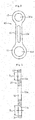
- the connecting rod 10 integrally comprises an annular large end portion 11, an annular small end portion 12 having a diameter smaller than a diameter of the large end portion 11, and a stem portion 13 coupling the large end portion 11 and the small end portion 12 to each other.
- a through-hole 11a is formed in the large end portion 11, and a through-hole 12a is formed in the small end portion 12.
- An inner peripheral surface of the large end portion 11 and an inner peripheral surface of the small end portion 12 (that is, a peripheral wall surrounding the through-hole 11a and a peripheral wall surrounding the through-hole 12a) are each formed into a cylindrical surface.
- a through-hole 13a is formed in the stem portion 13 to have a shape long and elongate in an extending direction of the stem portion 13 (in an up-and-down direction in the drawings).
- the connecting rod 10 is formed of a sintered metal.
- the connecting rod 10 is formed of an iron-based sintered metal containing iron as a main ingredient (for example, an iron content is 80% by mass or more, preferably 90% by mass or more).
- a Young's modulus of the connecting rod 10 is set to from 120 GPa or more to 180 GPa or less.
- a composition of the sintered metal for the connecting rod 10 is selected so that the Young's modulus of the connecting rod 10 is within the above-mentioned range.
- the sintered metal for the connecting rod 10 contains 0.1% to 5% by mass (preferably 0.5% to 4% by mass) of nickel, 0.1% to 3% by mass (preferably 0.3% to 2.5% by mass) of molybdenum, and 0.05% to 1% by mass (preferably 0.1% to 0.5% by mass) of carbon, and contains iron as the remaining composition.
- a density of the connecting rod 10 is set to, for example, 7.0 g/cm 3 or more, preferably 7.2 g/cm 3 or more. Further, the density of the connecting rod 10 is set to, for example, 7.8 g/cm 3 or less, practically 7.6 g/cm 3 or less.
- the roller bearing 20 comprises an outer ring 21, which serves as a bearing raceway ring having a raceway surface 21a formed into a cylindrical surface on an inner peripheral surface of the bearing raceway ring, a plurality of rollers 22 (needle rollers) accommodated along an inner periphery of the outer ring 21, and a cage 23 configured to retain the plurality of rollers 22 equiangularly.
- the roller bearing 30 has the same configuration as that of the roller bearing 20.
- the roller bearing 30 comprises an outer ring 31, which serves as a bearing raceway ring having a raceway surface 31a formed into a cylindrical surface on an inner peripheral surface of the bearing raceway ring, a plurality of rollers 32 (needle rollers) accommodated along an inner periphery of the outer ring 31, and a cage 33 configured to retain the plurality of rollers 32 equiangularly.
- the outer rings 21 and 31 are each formed into, for example, a cylindrical shape, and are press-fitted and fixed in the through-hole 11a of the large end portion 11 and the through-hole 12a of the small end portion 12 of the connecting rod 10, respectively.
- the outer rings 21 and 31 are formed of a material having a Young's modulus higher than that of the connecting rod 10.
- the outer rings 21 and 31 are formed of a material having a Young's modulus of more than 180 GPa. Meanwhile, when each of the outer rings 21 and 31 has extremely high Young's modulus, processing is difficult. Accordingly, the Young's modulus of each of the outer rings 21 and 31 is set to 240 GPa or less.
- the outer rings 21 and 31 are formed of an ingot material, for example, a steel material.
- the outer rings 21 and 31 are formed by cutting, forging, pressing, and the like.
- the outer rings 21 and 31 undergo heat treatment (for example, quenching treatment and tempering treatment) as needed.
- a quench-hardened layer is formed on a surface layer of each of the outer rings 21 and 31, with the result that surface hardness, specifically, hardness of the raceway surfaces 21a and 31a is set to HRC 58 or more.
- surface hardness of the raceway surfaces 21a and 31a of the outer rings 21 and 31 is set to HRC 65 or less.
- This value is an upper limit as surface hardness of a general bearing raceway ring that is formed of a steel material and excellent in cost.
- the raceway surfaces 21a and 31a of the outer rings 21 and 31 undergo finishing (for example, are finished by grinding).
- a circularity and a cylindricity of each of the raceway surfaces 21a and 31a are set to, for example, 20 ⁇ m or less, preferably 15 ⁇ m or less.
- the connecting rod 10 is formed of the sintered metal. Accordingly, rigidity of the large end portion 11 and the small end portion 12 may significantly fluctuate in a circumferential direction.
- the outer rings 21 and 31 are respectively press-fitted into the through-holes 11a and 12a of the connecting rod 10 having the above-mentioned configuration, stress applied to the outer rings 21 and 31 from the connecting rod 10 fluctuates significantly. As a result, the outer rings 21 and 31 may be deformed into distorted shapes.
- the outer rings 21 and 31 are each formed of a material having high Young's modulus, that is, a material having high rigidity. Accordingly, distortion of the outer rings 21 and 31 can be prevented.
- the hardness of the raceway surfaces 21a and 31a of the outer rings 21 and 31 are set to high hardness. Accordingly, functions as the raceway surfaces 21a and 31a are ensured, and deformation of the outer rings 21 and 31 can be further prevented when the outer rings 21 and 31 are press-fitted into the through-holes 11a and 12a of the connecting rod 10, respectively.
- the connecting rod 10 is formed of the sintered metal, and the outer rings 21 and 31 are formed of a hard material.
- the radial thicknesses T of the outer rings 21 and 31, and the interferences I between the outer ring 21 and the connecting rod 10 and between the outer ring 31 and the connecting rod 10 are set within predetermined ranges. In this manner, distortion of the outer rings 21 and 31 can be prevented, and degradation of the circularities of the raceway surfaces 21a and 31a can be prevented.
- the connecting rod 10 is manufactured through a compacting step, a sintering step, and a sizing step.
- raw material powder there is used powder containing completely alloyed steel powder (pre-alloyed powder) of iron, nickel, and molybdenum, and containing graphite powder as carbon powder.
- the raw material powder is filled into a forming die and undergoes compression molding, to thereby be molded into a green compact.
- rawmaterial powder M is filled into a cavity defined by a die 41, core rods 42a, 42b, and 42c, and a lower punch 43.
- an upper punch 44 is lowered to compress the raw material powder M, thereby molding a green compact 10' having substantially the same shape as that of the connecting rod 10 illustrated in FIG. 2 and FIG. 3 .
- the green compact 10' is sintered at a predetermined temperature for a predetermined time period.
- a sintered compact is obtained.
- the sintered compact is recompressed, and thus is increased in accuracy of dimension.
- the connecting rod 10 is obtained.
- outer peripheral surfaces and inner peripheral surfaces of a large end portion 11" and a small end portion 12" of a sintered compact 10" are molded. Specifically, first, as illustrated in FIG. 6 , the sintered compact 10" is placed in a space defined by a die 51 and core rods 52a and 52b. Then, as illustrated in FIG. 7 , the sintered compact 10" is pushed into the die 51 along an inner periphery of the die 51 by an upper punch 54. Thus, the sintered compact 10" is press-fitted into the die 51 and compressed by the upper punch 54 and the lower punch 53.
- the outer peripheral surfaces of the large end portion 11" and the small end portion 12" of the sintered compact 10" are molded by an inner peripheral surface of the die 51, and the inner peripheral surface of the large end portion 11" and the inner peripheral surface of the small end portion 12" are molded by an outer peripheral surface of the core rod 52a and an outer peripheral surface of the core rod 52b, respectively. Further, a relative positional relationship between the inner peripheral surface of the large end portion 11" and the inner peripheral surface of the small end portion 12" is corrected by the core rods 52a and 52b. After that, the connecting rod 10 is released from a sizing die.
- the outer rings 21 and 31 are respectively press-fitted into the through-hole 11a of the large end portion 11 and the through-hole 12a of the small end portion 12 of the connecting rod 10 that is formed as described above. After that, the rollers 22 and the cage 23 are assembled to the inner periphery of the outer ring 21, and the rollers 32 and the cage 33 are assembled to the inner periphery of the outer ring 31. In this manner, the connecting rod module 1 illustrated in FIG. 1 is completed.
- the configuration of the connecting rod 10 is not limited to the above-mentioned embodiment.
- the configuration of the connecting rod 10 is not limited to the above-mentioned configuration.
- a thin portion that is thinner than the other regions may be formed, or the entire stem portion 13 may be thinned.
- the through-hole 13a of the stem portion 13 may be omitted, and the stem portion 13 may be thick and solid similarly the large end portion 11 and the small end portion 12.
- the outer ring is press-fitted into the through-hole 12a of the small end portion 12, whereas the large end portion 13 is divided into a connecting rod body and a capmember.
- the connecting rod body and the cap member can be fixed to each other with a bolt or the like.
- roller bearings 20 and 30 are not limited to the above-mentioned configurations.
- a roller bearing of a so-called shell type in which a collar portion is formed at each axial end of an outer ring to protrude to a radially inner side, and is configured to retain rollers and a cage so as to prevent the rollers and the cage from slipping out of the outer ring.
- a bearing raceway ring (outer ring) was press-fitted into a connecting rod formed of a sintered metal, and a circularity and a cylindricity of a raceway surface (inner peripheral surface of an outer ring) were measured.
- the connecting rod was formed of a sintered metal having a Young's modulus of from 120 GPa or more to 180 GPa or less.
- the outer ring was formed of a material having a Young's modulus of from more than 180 GPa to 240 GPa or less.
- outer rings and the connecting rod are shown in Table 1 below.
- outer rings each having a radial thickness T of 1 mm (Example 1 to Example 9), and outer rings each having a radial thickness T of 1.5 mm (Example 10 to Example 18) were used.
- connecting rod connecting rods each having a through-hole having an inner diameter dimension D of 16 mm (Example 1 to Example 9), and connecting rods each having a through-hole having an inner diameter dimension D of 17 mm (Example 10 to Example 18) were used.
- An interference I between the outer ring and the connecting rod was set to 10 ⁇ m (Example 1 to Example 3 and Example 10 to Example 12), 20 ⁇ m (Example 4 to Example 6 and Example 13 to Example 15), or 30 ⁇ m (Example 7 to Example 9 and Example 16 to Example 18).
- Example 1 Thickness of outer ring T(mm) Press-fitting interference I [mm] Inner diameter of connecting rod D [mm] T/D I/D Circularity of connecting rod [ ⁇ m] (Before press-fitting outer ring) Cylindricity of connecting rod [ ⁇ m] (Before press-fitting outer ring) Circularity of connecting rod [ ⁇ m] (After press-fitting outer ring) Cylindricity of connecting rod [ ⁇ m] (After press-fitting outer ring) Extraction load [N]
- Example 1 1 0.01 16 0.063 0.00063 1.3 2.1 2.8 3.9 568
- Example 2 1 0.01 16 0.063 0.00063 3.4 3.8 1.4 2.3 629
- Example 3 1 0.01 16 0.063 0.00063 5.3 6.8 2.8 3.5 501
- Example 4 1 0.02 16 0.063 0.00125 2.0 3.3 7.0 9.1 1,079
- Example 5 1 0.02 16 0.063 0.00125 1.8 2.9 3.7 5.8 980
- Example 6 1
- Example 1 to Example 18 both the circularity and the cylindricity were represented by excellent values of 15 ⁇ m or less. Further, in Example 1 to Example 18, a ratio of T/D is set within a range of from 0.05 to 0.15 (specifically, from 0.06 to 0.10), and a ratio of I/D is set within a range of from 0.0004 to 0.004 (specifically, from 0.0005 to 0.002). Based on the above-mentioned facts, it was confirmed that by satisfying the numerical ranges of the present invention, deformation of the bearing raceway ring after the outer ring was press-fitted into the connecting rod was prevented so that the raceway surface having excellent circularity and cylindricity was obtained.
- an extraction load was 250 N or more.
- the extraction load was 900 N or more. Therefore, in Example 4 to Example 9 and Example 13 to Example 18, it was confirmed that both of excellent circularity of the raceway surface of the outer ring, and firm fixing between the connecting rod and the outer ring could be achieved.
Landscapes
- Engineering & Computer Science (AREA)
- General Engineering & Computer Science (AREA)
- Mechanical Engineering (AREA)
- Chemical & Material Sciences (AREA)
- Composite Materials (AREA)
- Manufacturing & Machinery (AREA)
- Materials Engineering (AREA)
- Shafts, Cranks, Connecting Bars, And Related Bearings (AREA)
- Rolling Contact Bearings (AREA)
Description
- The present invention relates to a connecting rod module comprising a connecting rod, and a bearing raceway ring that is press-fitted into at least one of a large end portion and a small end portion of the connecting rod.
- The connecting rod includes a small end portion to be coupled to a piston, a large end portion to be coupled to a crankshaft, and a stem portion coupling the small end portion and the large end portion to each other. For example, in
Patent Literature 1, there is disclosed a connecting rod module in which an outer ring (tubular member) having a raceway surface formed on an inner peripheral surface thereof is press-fitted into a through-hole of each of the large end portion and the small end portion of the connecting rod. - Patent Literature 1:
JP 7-293545 A - The small end portion and the large end portion of the connecting rod are each formed into an annular shape, but a region of the connecting rod in a vicinity of the stem portion and the other regions thereof are different in radial thickness. Accordingly, rigidity varies in a circumferential direction. Therefore, when the outer ring is press-fitted into the through-hole of each of the small end portion and the large end portion of the connecting rod, stress applied to the outer ring from the connecting rod varies in the circumferential direction. This varies a deformation amount of the outer ring in the circumferential direction. Thus, a circularity of the raceway surface of the outer ring may be degraded. Although the connecting rod is frequently formed of a forged product made of an ingot material, in a case of a relatively low-powered engine (such as a general-purpose engine to be used in a lawn mower and the like), the connecting rod is sometimes formed of a sintered metal in order to achieve reduction of manufacturing cost. The sintered metal has lower rigidity than the forged product made of an ingot material. Accordingly, when the connecting rod is formed of the sintered metal, a difference in rigidity between the small end portion and the large end portion in the circumferential direction is increased, with the result that differences in the deformation amount of the outer ring among circumferential positions are increased. Thus, the circularity of the raceway surface of the outer ring is prone to be degraded.
- Therefore, an object to be achieved by the present invention is to prevent degradation of a circularity of a raceway surface of a bearing raceway ring in a connecting rod module in which the bearing raceway ring (outer ring) is press-fitted into a through-hole of a large end portion and/or a small end portion of a connecting rod formed of a sintered metal.
- In order to solve the problem described above, according to one embodiment of the present invention, there is provided a connecting rod module, comprising: a connecting rod, which is formed of a sintered metal, and comprises a large end portion, a small end portion, and a stem portion for coupling the large end portion and the small end portion to each other; and a bearing raceway ring, which is fitted (that is, press-fitted), with an interference, into at least one of a through-hole formed in the large end portion and a through-hole formed in the small end portion, wherein the connecting rod has a Young's modulus of from 120 GPa or more to 180 GPa or less, wherein the bearing raceway ring has a Young's modulus of frommore than 180 GPa to 240 GPa or less, and wherein when T represents a radial thickness of the bearing raceway ring, D represents an inner diameter dimension of the through-hole into which the bearing raceway ring is press-fitted, and I represents an interference between the bearing raceway ring and a peripheral wall of the through-hole, the following equations are established:


- As described above, even when the connecting rod is formed of the sinteredmetal (specifically, the sintered metal having the Young's modulus of from 120 GPa to 180 GPa), deformation of the bearing raceway ring is prevented by forming the bearing raceway ring of a material having a Young's modulus higher than that of the connecting rod (specifically, a material having a Young' s modulus of from 180 GPa to 240 GPa). When the connecting rod and the bearing raceway ring are formed of the above-mentioned materials, and the thickness T of the bearing raceway ring and the interference I between the connecting rod and the bearing raceway ring are set to the above-mentioned ranges, distortion of the bearing raceway ring is prevented so that degradation of the circularity of the raceway surface can be prevented.
- The method of manufacturing a connecting rod module described above comprises the steps of: forming a green compact, which comprises a large end portion, a small end portion, and a coupling portion for coupling the large end portion and the small end portion to each other; sintering the green compact to form a sintered compact; sizing the sintered compact to form a connecting rod formed of a sintered metal; and press-fitting a bearing raceway ring into at least one of a through-hole formed in the large end portion of the connecting rod and a through-hole formed in the small end portion of the connecting rod.
- As described above, according to the present invention, degradation of the circularity of the raceway surface of the bearing raceway ring in which the bearing raceway ring is press-fitted into the through-hole of the large end portion and/or the small end portion of the connecting rod formed of the sintered metal can be prevented.
-
-
FIG. 1 is a sectional view for illustrating a connecting rod module according to an embodiment of the present invention. -
FIG. 2 is a front view for illustrating a connecting rod constructing the above-mentioned connecting rod module. -
FIG. 3 is a sectional view for illustrating the above-mentioned connecting rod. -
FIG. 4 is a sectional view for illustrating a compacting step for the above-mentioned connecting rod under a state in which raw material powder is filled into a die. -
FIG. 5 is a sectional view for illustrating the compacting step for the above-mentioned connecting rod under a state in which the raw material powder is compressed. -
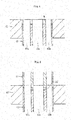
FIG. 6 is a sectional view for illustrating a sizing step for the above-mentioned connecting rod under a state before a sintered compact is compressed. -
FIG. 7 is a sectional view for illustrating the sizing step for the above-mentioned connecting rod under a state in which the sintered compact is compressed. - Now, an embodiment of the present invention is described with reference to the drawings.
- A connecting
rod module 1 according to one embodiment of the present invention is incorporated into an engine. For example, theconnecting rod module 1 is incorporated into a small-sized engine (general-purpose engine) that has a displacement of 100 cc or less (specifically, a displacement of 50 cc or less) and is provided in a bush cutter, a blower, or the like. As illustrated inFIG. 1 , theconnecting rod module 1 comprises a connectingrod 10 androller bearings - As illustrated in
FIG. 2 and FIG. 3 , the connectingrod 10 integrally comprises an annularlarge end portion 11, an annularsmall end portion 12 having a diameter smaller than a diameter of thelarge end portion 11, and astem portion 13 coupling thelarge end portion 11 and thesmall end portion 12 to each other. A through-hole 11a is formed in thelarge end portion 11, and a through-hole 12a is formed in thesmall end portion 12. An inner peripheral surface of thelarge end portion 11 and an inner peripheral surface of the small end portion 12 (that is, a peripheral wall surrounding the through-hole 11a and a peripheral wall surrounding the through-hole 12a) are each formed into a cylindrical surface. A through-hole 13a is formed in thestem portion 13 to have a shape long and elongate in an extending direction of the stem portion 13 (in an up-and-down direction in the drawings). - The connecting
rod 10 is formed of a sintered metal. Specifically, the connectingrod 10 is formed of an iron-based sintered metal containing iron as a main ingredient (for example, an iron content is 80% by mass or more, preferably 90% by mass or more). A Young's modulus of the connectingrod 10 is set to from 120 GPa or more to 180 GPa or less. - A composition of the sintered metal for the connecting
rod 10 is selected so that the Young's modulus of the connectingrod 10 is within the above-mentioned range. For example, the sintered metal for the connectingrod 10 contains 0.1% to 5% by mass (preferably 0.5% to 4% by mass) of nickel, 0.1% to 3% by mass (preferably 0.3% to 2.5% by mass) of molybdenum, and 0.05% to 1% by mass (preferably 0.1% to 0.5% by mass) of carbon, and contains iron as the remaining composition. - A density of the connecting
rod 10 is set to, for example, 7.0 g/cm3 or more, preferably 7.2 g/cm3 or more. Further, the density of the connectingrod 10 is set to, for example, 7.8 g/cm3 or less, practically 7.6 g/cm3 or less. - As illustrated in
FIG. 1 , the roller bearing 20 comprises anouter ring 21, which serves as a bearing raceway ring having araceway surface 21a formed into a cylindrical surface on an inner peripheral surface of the bearing raceway ring, a plurality of rollers 22 (needle rollers) accommodated along an inner periphery of theouter ring 21, and acage 23 configured to retain the plurality ofrollers 22 equiangularly. The roller bearing 30 has the same configuration as that of the roller bearing 20. The roller bearing 30 comprises anouter ring 31, which serves as a bearing raceway ring having araceway surface 31a formed into a cylindrical surface on an inner peripheral surface of the bearing raceway ring, a plurality of rollers 32 (needle rollers) accommodated along an inner periphery of theouter ring 31, and acage 33 configured to retain the plurality ofrollers 32 equiangularly. - The
outer rings hole 11a of thelarge end portion 11 and the through-hole 12a of thesmall end portion 12 of the connectingrod 10, respectively. Theouter rings rod 10. Specifically, theouter rings outer rings outer rings - The
outer rings outer rings outer rings outer rings raceway surfaces outer rings outer rings raceway surfaces - In this embodiment, the connecting
rod 10 is formed of the sintered metal. Accordingly, rigidity of thelarge end portion 11 and thesmall end portion 12 may significantly fluctuate in a circumferential direction. When theouter rings holes rod 10 having the above-mentioned configuration, stress applied to theouter rings rod 10 fluctuates significantly. As a result, the outer rings 21 and 31 may be deformed into distorted shapes. In this embodiment, as described above, the outer rings 21 and 31 are each formed of a material having high Young's modulus, that is, a material having high rigidity. Accordingly, distortion of theouter rings - Further, in this embodiment, the hardness of the raceway surfaces 21a and 31a of the
outer rings outer rings outer rings holes rod 10, respectively. - In addition, in this embodiment, with respect to an inner diameter dimension D11 of the through-
hole 11a of thelarge end portion 11, a radial thickness T21 of the outer ring 21 (specifically, a thickness in a forming region of theraceway surface 21a) satisfies T21=(0.05-0.15)×D11. Similarly, with respect to an inner diameter dimension D12 of the through-hole 12a of thesmall end portion 12, a radial thickness T31 of the outer ring 31 (specifically, a thickness in a forming region of theraceway surface 31a) satisfies T31=(0.05∼0.15)×D12. - When a thickness T of an outer ring is smaller than 0.05D, rigidity of the
outer rings outer rings holes rod 10. Meanwhile, when the thickness T of the outer ring is larger than 0.15D, the thicknesses of theouter rings rod module 1 is increased. - In addition, in this embodiment, an interference I1 between the
outer ring 21 and the inner peripheral surface of the large end portion 11 (peripheral wall of the through-hole 11a), that is, a difference I1 before assembly between an outer diameter dimension D21 of theouter ring 21 and the inner diameter dimension D11 of the through-hole 11a satisfies I1=(0.0004∼0.004)×D11. Similarly, an interference I2 between theouter ring 31 and the inner peripheral surface of the small end portion 12 (peripheral wall of the through-hole 12a), that is, a difference I2 before assembly between an outer diameter dimension D31 of theouter ring 31 and the inner diameter dimension D12 of the through-hole 12a satisfies I2=(0.0004∼0.004)×D12. - When an interference I is smaller than 0. 0004D, a fixing force is insufficient, with the result that the
outer rings rod 10 . Thus, unbalanced load is applied to theroller bearings holes rod 10. As a result, the circularities are increased, and noise and reduction in bearing lifetime are caused. - As described above, the connecting
rod 10 is formed of the sintered metal, and theouter rings outer rings outer ring 21 and the connectingrod 10 and between theouter ring 31 and the connectingrod 10 are set within predetermined ranges. In this manner, distortion of theouter rings - Now, a method of manufacturing the connecting
rod 10 is described. The connectingrod 10 is manufactured through a compacting step, a sintering step, and a sizing step. - In the compacting step, first, various kinds of powder are mixed together and formed into raw material powder. In this embodiment, as the raw material powder, there is used powder containing completely alloyed steel powder (pre-alloyed powder) of iron, nickel, and molybdenum, and containing graphite powder as carbon powder. The raw material powder is filled into a forming die and undergoes compression molding, to thereby be molded into a green compact. Specifically, as illustrated in
FIG. 4 , rawmaterial powder M is filled into a cavity defined by adie 41,core rods lower punch 43. Then, as illustrated inFIG. 5 , anupper punch 44 is lowered to compress the raw material powder M, thereby molding a green compact 10' having substantially the same shape as that of the connectingrod 10 illustrated inFIG. 2 and FIG. 3 . - In the sintering step, the green compact 10' is sintered at a predetermined temperature for a predetermined time period. Thus, a sintered compact is obtained.
- In the sizing step, the sintered compact is recompressed, and thus is increased in accuracy of dimension. Thus, the connecting
rod 10 is obtained. In this embodiment, particularly outer peripheral surfaces and inner peripheral surfaces of alarge end portion 11" and asmall end portion 12" of a sintered compact 10" are molded. Specifically, first, as illustrated inFIG. 6 , the sintered compact 10" is placed in a space defined by adie 51 andcore rods FIG. 7 , the sintered compact 10" is pushed into thedie 51 along an inner periphery of the die 51 by anupper punch 54. Thus, the sintered compact 10" is press-fitted into thedie 51 and compressed by theupper punch 54 and thelower punch 53. In this manner, the outer peripheral surfaces of thelarge end portion 11" and thesmall end portion 12" of the sintered compact 10" are molded by an inner peripheral surface of the die 51, and the inner peripheral surface of thelarge end portion 11" and the inner peripheral surface of thesmall end portion 12" are molded by an outer peripheral surface of thecore rod 52a and an outer peripheral surface of thecore rod 52b, respectively. Further, a relative positional relationship between the inner peripheral surface of thelarge end portion 11" and the inner peripheral surface of thesmall end portion 12" is corrected by thecore rods rod 10 is released from a sizing die. - The outer rings 21 and 31 are respectively press-fitted into the through-
hole 11a of thelarge end portion 11 and the through-hole 12a of thesmall end portion 12 of the connectingrod 10 that is formed as described above. After that, therollers 22 and thecage 23 are assembled to the inner periphery of theouter ring 21, and therollers 32 and thecage 33 are assembled to the inner periphery of theouter ring 31. In this manner, the connectingrod module 1 illustrated inFIG. 1 is completed. - The present invention is not limited to the above-mentioned embodiment. For example, the configuration of the connecting
rod 10 is not limited to the above-mentioned configuration. In a region forming the through-hole 13a of thestem portion 13, a thin portion that is thinner than the other regions may be formed, or theentire stem portion 13 may be thinned. Alternatively, the through-hole 13a of thestem portion 13 may be omitted, and thestem portion 13 may be thick and solid similarly thelarge end portion 11 and thesmall end portion 12. - Further, in the above-mentioned embodiment, description is made of the case where the
outer rings hole 11a of thelarge end portion 11 and the through-hole 12a of thesmall end portion 12 of the connectingrod 10, but the present invention is not limited thereto. There may be adopted such a configuration that the outer ring is press-fitted into one of the through-hole 11a of thelarge end portion 11 and the through-hole 12a of thesmall end portion 12 of the connectingrod 10, and that the outer ring is not press-fitted into another one of the through-holes hole 12a of thesmall end portion 12, whereas thelarge end portion 13 is divided into a connecting rod body and a capmember. The connecting rod body and the cap member can be fixed to each other with a bolt or the like. - Further, also the configurations of the
roller bearings roller bearing 20 and theroller bearing 30, there may be adopted a roller bearing of a so-called shell type in which a collar portion is formed at each axial end of an outer ring to protrude to a radially inner side, and is configured to retain rollers and a cage so as to prevent the rollers and the cage from slipping out of the outer ring. - In order to confirm effects of the present invention, a bearing raceway ring (outer ring) was press-fitted into a connecting rod formed of a sintered metal, and a circularity and a cylindricity of a raceway surface (inner peripheral surface of an outer ring) were measured. The connecting rod was formed of a sintered metal having a Young's modulus of from 120 GPa or more to 180 GPa or less. The outer ring was formed of a material having a Young's modulus of from more than 180 GPa to 240 GPa or less.
- Dimensions of the outer ring and the connecting rod are shown in Table 1 below. As the outer ring, outer rings each having a radial thickness T of 1 mm (Example 1 to Example 9), and outer rings each having a radial thickness T of 1.5 mm (Example 10 to Example 18) were used. As the connecting rod, connecting rods each having a through-hole having an inner diameter dimension D of 16 mm (Example 1 to Example 9), and connecting rods each having a through-hole having an inner diameter dimension D of 17 mm (Example 10 to Example 18) were used. An interference I between the outer ring and the connecting rod was set to 10 µm (Example 1 to Example 3 and Example 10 to Example 12), 20 µm (Example 4 to Example 6 and Example 13 to Example 15), or 30 µm (Example 7 to Example 9 and Example 16 to Example 18).
[Table 1] Thickness of outer ring T(mm) Press-fitting interference I [mm] Inner diameter of connecting rod D [mm] T/D I/D Circularity of connecting rod [µm] (Before press-fitting outer ring) Cylindricity of connecting rod [µm] (Before press-fitting outer ring) Circularity of connecting rod [µm] (After press-fitting outer ring) Cylindricity of connecting rod [µm] (After press-fitting outer ring) Extraction load [N] Example 1 1 0.01 16 0.063 0.00063 1.3 2.1 2.8 3.9 568 Example 2 1 0.01 16 0.063 0.00063 3.4 3.8 1.4 2.3 629 Example 3 1 0.01 16 0.063 0.00063 5.3 6.8 2.8 3.5 501 Example 4 1 0.02 16 0.063 0.00125 2.0 3.3 7.0 9.1 1,079 Example 5 1 0.02 16 0.063 0.00125 1.8 2.9 3.7 5.8 980 Example 6 1 0.02 16 0.063 0.00125 2.4 3.2 5.8 7.1 917 Example 7 1 0.03 16 0.063 0.00188 1.1 2.9 8.5 10.4 1,300 Example 8 1 0.03 16 0.063 0.00188 2.1 3.7 10.1 13.8 1,380 Example 9 1 0.03 16 0.063 0.00188 1.2 4.5 6.9 8.5 1,360 Example 10 1.5 0.01 17 0.088 0.00059 3.4 6.1 1.8 2.8 287 Example 11 1.5 0.01 17 0.088 0.00059 5.9 9.0 3.9 4.8 359 Example 12 1.5 0.01 17 0.088 0.00059 8.5 9.1 3.7 5.3 334 Example 13 1.5 0.02 17 0.088 0.00118 9.7 13.4 7.0 9.6 1,119 Example 14 1.5 0.02 17 0.088 0.00118 11.8 14.9 8.4 11.2 1,155 Example 15 1.5 0.02 17 0.088 0.0011B 12.1 17.3 6.8 10.7 1,073 Example 16 1.5 0.03 17 0.088 0.00176 8.9 14.1 7.0 8.4 1,132 Example 17 1.5 0.03 17 0.088 0.00176 13.1 17.6 10.5 14.5 1,350 Example 18 1.5 0.03 17 0.088 0.00176 10.7 15.3 10.1 11.4 1,210 - As a result, in all of Example 1 to Example 18, both the circularity and the cylindricity were represented by excellent values of 15 µm or less. Further, in Example 1 to Example 18, a ratio of T/D is set within a range of from 0.05 to 0.15 (specifically, from 0.06 to 0.10), and a ratio of I/D is set within a range of from 0.0004 to 0.004 (specifically, from 0.0005 to 0.002). Based on the above-mentioned facts, it was confirmed that by satisfying the numerical ranges of the present invention, deformation of the bearing raceway ring after the outer ring was press-fitted into the connecting rod was prevented so that the raceway surface having excellent circularity and cylindricity was obtained.
- Further, in all of Examples, an extraction load was 250 N or more. Particularly in Example 4 to Example 9 and Example 13 to Example 18 in which the interference I was set to 20 µm or more (I/D≥0.001), the extraction load was 900 N or more. Therefore, in Example 4 to Example 9 and Example 13 to Example 18, it was confirmed that both of excellent circularity of the raceway surface of the outer ring, and firm fixing between the connecting rod and the outer ring could be achieved.
-
- 1
- connecting rod module
- 10
- connecting rod
- 11
- large end portion
- 11a
- through-hole
- 12
- small end portion
- 12a
- through-hole
- 13
- stem portion
- 20, 30
- roller bearing
- 21, 31
- outer ring (bearing raceway ring)
- 21a, 31a
- raceway surface
- 23, 33
- cage
Claims (2)
- A connecting rod module, comprising:a connecting rod, which is formed of a sintered metal, and comprises a large end portion, a small end portion, and a stem portion for coupling the large end portion and the small end portion to each other; anda bearing raceway ring, which is fitted, with an interference, into at least one of a through-hole formed in the large end portion and a through-hole formed in the small end portion,wherein the connecting rod has a Young's modulus of from 120 GPa or more to 180 GPa or less,wherein the bearing raceway ring has a Young's modulus of from more than 180 GPa to 240 GPa or less, andwherein when T represents a radial thickness of the bearing raceway ring, D represents an inner diameter dimension of the through-hole into which the bearing raceway ring is press-fitted, and I represents an interference between the bearing raceway ring and a peripheral wall of the through-hole, the following equations are established:


- A method of manufacturing a connecting rod module, comprising the steps of:forming a green compact, which comprises a large end portion, a small end portion, and a coupling portion for coupling the large end portion and the small end portion to each other;sintering the green compact to form a sintered compact;sizing the sintered compact to form a connecting rod formed of a sintered metal; andpress-fitting a bearing raceway ring into at least one of a through-hole formed in the large end portion of the connecting rod and a through-hole formed in the small end portion of the connecting rod,wherein the connecting rod has a Young's modulus of from 120 GPa or more to 180 GPa or less,wherein the bearing raceway ring has a Young's modulus of from more than 180 GPa to 240 GPa or less, andwhen T represents a radial thickness of the bearing raceway ring, D represents an inner diameter dimension of the through-hole into which the bearing raceway ring is press-fitted, and I represents an interference between the bearing raceway ring and a peripheral wall of the through-hole, the following equations are established:


Applications Claiming Priority (2)
| Application Number | Priority Date | Filing Date | Title |
|---|---|---|---|
| JP2015188648A JP6602623B2 (en) | 2015-09-25 | 2015-09-25 | Connecting rod module and manufacturing method thereof |
| PCT/JP2016/075408 WO2017051674A1 (en) | 2015-09-25 | 2016-08-31 | Connecting rod module and production method therefor |
Publications (3)
| Publication Number | Publication Date |
|---|---|
| EP3354915A1 true EP3354915A1 (en) | 2018-08-01 |
| EP3354915A4 EP3354915A4 (en) | 2019-04-17 |
| EP3354915B1 EP3354915B1 (en) | 2020-03-18 |
Family
ID=58386020
Family Applications (1)
| Application Number | Title | Priority Date | Filing Date |
|---|---|---|---|
| EP16848462.4A Active EP3354915B1 (en) | 2015-09-25 | 2016-08-31 | Connecting rod module and production method therefor |
Country Status (5)
| Country | Link |
|---|---|
| US (2) | US10718370B2 (en) |
| EP (1) | EP3354915B1 (en) |
| JP (1) | JP6602623B2 (en) |
| CN (1) | CN108026959B (en) |
| WO (1) | WO2017051674A1 (en) |
Families Citing this family (3)
| Publication number | Priority date | Publication date | Assignee | Title |
|---|---|---|---|---|
| US20190024702A1 (en) * | 2017-07-20 | 2019-01-24 | Bryan Gill | Method of Designing and Producing Connecting Rods formed of Fiber Composite Material |
| US11806946B1 (en) | 2017-07-20 | 2023-11-07 | Awa Forged Composites, Llc | Method of designing and producing carbon fiber connecting rods |
| JP7320365B2 (en) | 2019-03-28 | 2023-08-03 | Ntn株式会社 | Sintered metal connecting rod and manufacturing method thereof |
Family Cites Families (12)
| Publication number | Priority date | Publication date | Assignee | Title |
|---|---|---|---|---|
| US3563677A (en) * | 1969-04-01 | 1971-02-16 | Carrier Corp | Compressor |
| JPH0826894B2 (en) * | 1992-08-28 | 1996-03-21 | 大同メタル工業株式会社 | Slide bearing for light alloy housing |
| JPH07293545A (en) * | 1994-04-19 | 1995-11-07 | Kioritz Corp | Connecting rod |
| US6752120B2 (en) | 2002-03-25 | 2004-06-22 | Toyoda Koki Kabushiki Kaisha | Crankshaft and engine |
| JP3890560B2 (en) * | 2002-05-29 | 2007-03-07 | 株式会社ジェイテクト | Crankshaft and engine |
| JP2003322138A (en) * | 2002-04-30 | 2003-11-14 | Ntn Corp | Connecting rod and connecting rod with bearing |
| JP2007024235A (en) * | 2005-07-20 | 2007-02-01 | Ntn Corp | Connecting rod with bearing for two-cycle engine |
| JP4789837B2 (en) * | 2007-03-22 | 2011-10-12 | トヨタ自動車株式会社 | Iron-based sintered body and manufacturing method thereof |
| US20100028190A1 (en) * | 2008-07-31 | 2010-02-04 | Gm Global Technology Operations, Inc. | Method of making powder metal parts using shock loading |
| JP5762698B2 (en) * | 2010-06-24 | 2015-08-12 | Ntn株式会社 | Split needle bearing and bearing device |
| WO2013064655A1 (en) * | 2011-11-02 | 2013-05-10 | Mauser-Werke Oberndorf Maschinenbau Gmbh | Method and device for inserting a bearing bush |
| JP6011971B2 (en) * | 2013-02-05 | 2016-10-25 | 本田技研工業株式会社 | Power transmission device for vehicle |
-
2015
- 2015-09-25 JP JP2015188648A patent/JP6602623B2/en active Active
-
2016
- 2016-08-31 EP EP16848462.4A patent/EP3354915B1/en active Active
- 2016-08-31 CN CN201680053050.3A patent/CN108026959B/en not_active Expired - Fee Related
- 2016-08-31 WO PCT/JP2016/075408 patent/WO2017051674A1/en not_active Ceased
- 2016-08-31 US US15/762,223 patent/US10718370B2/en active Active
-
2020
- 2020-03-03 US US16/807,329 patent/US10718371B1/en active Active
Also Published As
| Publication number | Publication date |
|---|---|
| EP3354915B1 (en) | 2020-03-18 |
| WO2017051674A1 (en) | 2017-03-30 |
| US10718371B1 (en) | 2020-07-21 |
| CN108026959A (en) | 2018-05-11 |
| US20200217355A1 (en) | 2020-07-09 |
| EP3354915A4 (en) | 2019-04-17 |
| JP2017062015A (en) | 2017-03-30 |
| JP6602623B2 (en) | 2019-11-06 |
| CN108026959B (en) | 2020-09-01 |
| US10718370B2 (en) | 2020-07-21 |
| US20180274583A1 (en) | 2018-09-27 |
Similar Documents
| Publication | Publication Date | Title |
|---|---|---|
| US12066060B2 (en) | Sintered metal connecting rod | |
| US10718371B1 (en) | Method of manufacturing connecting rod module | |
| US9939015B2 (en) | Sintered bearing | |
| EP2602501A1 (en) | Manufacturing method for bearing outer ring | |
| EP3128193B1 (en) | Bearing ring and roller bearing having said bearing ring | |
| GB2033975A (en) | Method of manufacturing composite rings for rolling-contact bearings | |
| US20190145461A1 (en) | Method for producing a toothed sintered component | |
| JP2017187173A (en) | Con rod, con rod module and method for manufacturing the same | |
| US20160023274A1 (en) | Machine part and process for producing same | |
| US11137021B2 (en) | Rolling bearing ring by metal injection molding process | |
| JP2009208135A (en) | Method for manufacturing semifinished product for holder of needle roller bearing by cold rolling | |
| EP3358206B1 (en) | Sintered bearing | |
| WO2017170913A1 (en) | Connecting rod, connecting rod module, and method for manufacturing same | |
| JP2003286504A (en) | Method for manufacturing sintered member with bore superior in coaxiality accuracy | |
| JP2007085493A (en) | Shell type roller bearing for laminated connecting rod and connecting rod assembly | |
| JPH0647686B2 (en) | Sizing method for iron-based sintered body | |
| JP2007170562A (en) | Shell type roller bearing for laminated connecting rod and connecting rod assembly | |
| JP4508588B2 (en) | Shell needle roller bearing | |
| JP2005090589A (en) | Shell type needle roller bearing |
Legal Events
| Date | Code | Title | Description |
|---|---|---|---|
| STAA | Information on the status of an ep patent application or granted ep patent |
Free format text: STATUS: THE INTERNATIONAL PUBLICATION HAS BEEN MADE |
|
| PUAI | Public reference made under article 153(3) epc to a published international application that has entered the european phase |
Free format text: ORIGINAL CODE: 0009012 |
|
| STAA | Information on the status of an ep patent application or granted ep patent |
Free format text: STATUS: REQUEST FOR EXAMINATION WAS MADE |
|
| 17P | Request for examination filed |
Effective date: 20180419 |
|
| AK | Designated contracting states |
Kind code of ref document: A1 Designated state(s): AL AT BE BG CH CY CZ DE DK EE ES FI FR GB GR HR HU IE IS IT LI LT LU LV MC MK MT NL NO PL PT RO RS SE SI SK SM TR |
|
| AX | Request for extension of the european patent |
Extension state: BA ME |
|
| DAV | Request for validation of the european patent (deleted) | ||
| DAX | Request for extension of the european patent (deleted) | ||
| A4 | Supplementary search report drawn up and despatched |
Effective date: 20190314 |
|
| RIC1 | Information provided on ipc code assigned before grant |
Ipc: F16C 7/02 20060101AFI20190308BHEP Ipc: F16C 33/58 20060101ALI20190308BHEP Ipc: F16C 35/067 20060101ALI20190308BHEP Ipc: F16C 19/46 20060101ALN20190308BHEP |
|
| GRAP | Despatch of communication of intention to grant a patent |
Free format text: ORIGINAL CODE: EPIDOSNIGR1 |
|
| STAA | Information on the status of an ep patent application or granted ep patent |
Free format text: STATUS: GRANT OF PATENT IS INTENDED |
|
| RIC1 | Information provided on ipc code assigned before grant |
Ipc: F16C 19/46 20060101ALN20190829BHEP Ipc: F16C 33/58 20060101ALI20190829BHEP Ipc: F16C 35/067 20060101ALI20190829BHEP Ipc: F16C 7/02 20060101AFI20190829BHEP |
|
| RIC1 | Information provided on ipc code assigned before grant |
Ipc: F16C 35/067 20060101ALI20190903BHEP Ipc: F16C 7/02 20060101AFI20190903BHEP Ipc: F16C 19/46 20060101ALN20190903BHEP Ipc: F16C 33/58 20060101ALI20190903BHEP |
|
| INTG | Intention to grant announced |
Effective date: 20190919 |
|
| GRAJ | Information related to disapproval of communication of intention to grant by the applicant or resumption of examination proceedings by the epo deleted |
Free format text: ORIGINAL CODE: EPIDOSDIGR1 |
|
| STAA | Information on the status of an ep patent application or granted ep patent |
Free format text: STATUS: REQUEST FOR EXAMINATION WAS MADE |
|
| GRAP | Despatch of communication of intention to grant a patent |
Free format text: ORIGINAL CODE: EPIDOSNIGR1 |
|
| INTC | Intention to grant announced (deleted) | ||
| STAA | Information on the status of an ep patent application or granted ep patent |
Free format text: STATUS: GRANT OF PATENT IS INTENDED |
|
| RIC1 | Information provided on ipc code assigned before grant |
Ipc: F16C 7/02 20060101AFI20191118BHEP Ipc: F16C 35/067 20060101ALI20191118BHEP Ipc: F16C 19/46 20060101ALN20191118BHEP Ipc: F16C 33/58 20060101ALI20191118BHEP |
|
| INTG | Intention to grant announced |
Effective date: 20191219 |
|
| GRAS | Grant fee paid |
Free format text: ORIGINAL CODE: EPIDOSNIGR3 |
|
| GRAA | (expected) grant |
Free format text: ORIGINAL CODE: 0009210 |
|
| STAA | Information on the status of an ep patent application or granted ep patent |
Free format text: STATUS: THE PATENT HAS BEEN GRANTED |
|
| AK | Designated contracting states |
Kind code of ref document: B1 Designated state(s): AL AT BE BG CH CY CZ DE DK EE ES FI FR GB GR HR HU IE IS IT LI LT LU LV MC MK MT NL NO PL PT RO RS SE SI SK SM TR |
|
| REG | Reference to a national code |
Ref country code: GB Ref legal event code: FG4D |
|
| REG | Reference to a national code |
Ref country code: DE Ref legal event code: R096 Ref document number: 602016032274 Country of ref document: DE |
|
| REG | Reference to a national code |
Ref country code: AT Ref legal event code: REF Ref document number: 1246215 Country of ref document: AT Kind code of ref document: T Effective date: 20200415 Ref country code: IE Ref legal event code: FG4D |
|
| PG25 | Lapsed in a contracting state [announced via postgrant information from national office to epo] |
Ref country code: FI Free format text: LAPSE BECAUSE OF FAILURE TO SUBMIT A TRANSLATION OF THE DESCRIPTION OR TO PAY THE FEE WITHIN THE PRESCRIBED TIME-LIMIT Effective date: 20200318 Ref country code: RS Free format text: LAPSE BECAUSE OF FAILURE TO SUBMIT A TRANSLATION OF THE DESCRIPTION OR TO PAY THE FEE WITHIN THE PRESCRIBED TIME-LIMIT Effective date: 20200318 Ref country code: NO Free format text: LAPSE BECAUSE OF FAILURE TO SUBMIT A TRANSLATION OF THE DESCRIPTION OR TO PAY THE FEE WITHIN THE PRESCRIBED TIME-LIMIT Effective date: 20200618 |
|
| REG | Reference to a national code |
Ref country code: NL Ref legal event code: MP Effective date: 20200318 |
|
| PG25 | Lapsed in a contracting state [announced via postgrant information from national office to epo] |
Ref country code: BG Free format text: LAPSE BECAUSE OF FAILURE TO SUBMIT A TRANSLATION OF THE DESCRIPTION OR TO PAY THE FEE WITHIN THE PRESCRIBED TIME-LIMIT Effective date: 20200618 Ref country code: LV Free format text: LAPSE BECAUSE OF FAILURE TO SUBMIT A TRANSLATION OF THE DESCRIPTION OR TO PAY THE FEE WITHIN THE PRESCRIBED TIME-LIMIT Effective date: 20200318 Ref country code: SE Free format text: LAPSE BECAUSE OF FAILURE TO SUBMIT A TRANSLATION OF THE DESCRIPTION OR TO PAY THE FEE WITHIN THE PRESCRIBED TIME-LIMIT Effective date: 20200318 Ref country code: GR Free format text: LAPSE BECAUSE OF FAILURE TO SUBMIT A TRANSLATION OF THE DESCRIPTION OR TO PAY THE FEE WITHIN THE PRESCRIBED TIME-LIMIT Effective date: 20200619 Ref country code: HR Free format text: LAPSE BECAUSE OF FAILURE TO SUBMIT A TRANSLATION OF THE DESCRIPTION OR TO PAY THE FEE WITHIN THE PRESCRIBED TIME-LIMIT Effective date: 20200318 |
|
| REG | Reference to a national code |
Ref country code: LT Ref legal event code: MG4D |
|
| PG25 | Lapsed in a contracting state [announced via postgrant information from national office to epo] |
Ref country code: NL Free format text: LAPSE BECAUSE OF FAILURE TO SUBMIT A TRANSLATION OF THE DESCRIPTION OR TO PAY THE FEE WITHIN THE PRESCRIBED TIME-LIMIT Effective date: 20200318 |
|
| PG25 | Lapsed in a contracting state [announced via postgrant information from national office to epo] |
Ref country code: PT Free format text: LAPSE BECAUSE OF FAILURE TO SUBMIT A TRANSLATION OF THE DESCRIPTION OR TO PAY THE FEE WITHIN THE PRESCRIBED TIME-LIMIT Effective date: 20200812 Ref country code: IS Free format text: LAPSE BECAUSE OF FAILURE TO SUBMIT A TRANSLATION OF THE DESCRIPTION OR TO PAY THE FEE WITHIN THE PRESCRIBED TIME-LIMIT Effective date: 20200718 Ref country code: RO Free format text: LAPSE BECAUSE OF FAILURE TO SUBMIT A TRANSLATION OF THE DESCRIPTION OR TO PAY THE FEE WITHIN THE PRESCRIBED TIME-LIMIT Effective date: 20200318 Ref country code: SK Free format text: LAPSE BECAUSE OF FAILURE TO SUBMIT A TRANSLATION OF THE DESCRIPTION OR TO PAY THE FEE WITHIN THE PRESCRIBED TIME-LIMIT Effective date: 20200318 Ref country code: SM Free format text: LAPSE BECAUSE OF FAILURE TO SUBMIT A TRANSLATION OF THE DESCRIPTION OR TO PAY THE FEE WITHIN THE PRESCRIBED TIME-LIMIT Effective date: 20200318 Ref country code: EE Free format text: LAPSE BECAUSE OF FAILURE TO SUBMIT A TRANSLATION OF THE DESCRIPTION OR TO PAY THE FEE WITHIN THE PRESCRIBED TIME-LIMIT Effective date: 20200318 Ref country code: LT Free format text: LAPSE BECAUSE OF FAILURE TO SUBMIT A TRANSLATION OF THE DESCRIPTION OR TO PAY THE FEE WITHIN THE PRESCRIBED TIME-LIMIT Effective date: 20200318 Ref country code: CZ Free format text: LAPSE BECAUSE OF FAILURE TO SUBMIT A TRANSLATION OF THE DESCRIPTION OR TO PAY THE FEE WITHIN THE PRESCRIBED TIME-LIMIT Effective date: 20200318 |
|
| REG | Reference to a national code |
Ref country code: AT Ref legal event code: MK05 Ref document number: 1246215 Country of ref document: AT Kind code of ref document: T Effective date: 20200318 |
|
| REG | Reference to a national code |
Ref country code: DE Ref legal event code: R097 Ref document number: 602016032274 Country of ref document: DE |
|
| PLBE | No opposition filed within time limit |
Free format text: ORIGINAL CODE: 0009261 |
|
| STAA | Information on the status of an ep patent application or granted ep patent |
Free format text: STATUS: NO OPPOSITION FILED WITHIN TIME LIMIT |
|
| PG25 | Lapsed in a contracting state [announced via postgrant information from national office to epo] |
Ref country code: IT Free format text: LAPSE BECAUSE OF FAILURE TO SUBMIT A TRANSLATION OF THE DESCRIPTION OR TO PAY THE FEE WITHIN THE PRESCRIBED TIME-LIMIT Effective date: 20200318 Ref country code: DK Free format text: LAPSE BECAUSE OF FAILURE TO SUBMIT A TRANSLATION OF THE DESCRIPTION OR TO PAY THE FEE WITHIN THE PRESCRIBED TIME-LIMIT Effective date: 20200318 Ref country code: AT Free format text: LAPSE BECAUSE OF FAILURE TO SUBMIT A TRANSLATION OF THE DESCRIPTION OR TO PAY THE FEE WITHIN THE PRESCRIBED TIME-LIMIT Effective date: 20200318 Ref country code: ES Free format text: LAPSE BECAUSE OF FAILURE TO SUBMIT A TRANSLATION OF THE DESCRIPTION OR TO PAY THE FEE WITHIN THE PRESCRIBED TIME-LIMIT Effective date: 20200318 |
|
| 26N | No opposition filed |
Effective date: 20201221 |
|
| PG25 | Lapsed in a contracting state [announced via postgrant information from national office to epo] |
Ref country code: PL Free format text: LAPSE BECAUSE OF FAILURE TO SUBMIT A TRANSLATION OF THE DESCRIPTION OR TO PAY THE FEE WITHIN THE PRESCRIBED TIME-LIMIT Effective date: 20200318 |
|
| PG25 | Lapsed in a contracting state [announced via postgrant information from national office to epo] |
Ref country code: MC Free format text: LAPSE BECAUSE OF FAILURE TO SUBMIT A TRANSLATION OF THE DESCRIPTION OR TO PAY THE FEE WITHIN THE PRESCRIBED TIME-LIMIT Effective date: 20200318 |
|
| REG | Reference to a national code |
Ref country code: CH Ref legal event code: PL |
|
| GBPC | Gb: european patent ceased through non-payment of renewal fee |
Effective date: 20200831 |
|
| PG25 | Lapsed in a contracting state [announced via postgrant information from national office to epo] |
Ref country code: CH Free format text: LAPSE BECAUSE OF NON-PAYMENT OF DUE FEES Effective date: 20200831 Ref country code: LI Free format text: LAPSE BECAUSE OF NON-PAYMENT OF DUE FEES Effective date: 20200831 Ref country code: LU Free format text: LAPSE BECAUSE OF NON-PAYMENT OF DUE FEES Effective date: 20200831 |
|
| REG | Reference to a national code |
Ref country code: BE Ref legal event code: MM Effective date: 20200831 |
|
| PG25 | Lapsed in a contracting state [announced via postgrant information from national office to epo] |
Ref country code: SI Free format text: LAPSE BECAUSE OF FAILURE TO SUBMIT A TRANSLATION OF THE DESCRIPTION OR TO PAY THE FEE WITHIN THE PRESCRIBED TIME-LIMIT Effective date: 20200318 |
|
| PG25 | Lapsed in a contracting state [announced via postgrant information from national office to epo] |
Ref country code: BE Free format text: LAPSE BECAUSE OF NON-PAYMENT OF DUE FEES Effective date: 20200831 Ref country code: IE Free format text: LAPSE BECAUSE OF NON-PAYMENT OF DUE FEES Effective date: 20200831 Ref country code: GB Free format text: LAPSE BECAUSE OF NON-PAYMENT OF DUE FEES Effective date: 20200831 |
|
| PG25 | Lapsed in a contracting state [announced via postgrant information from national office to epo] |
Ref country code: TR Free format text: LAPSE BECAUSE OF FAILURE TO SUBMIT A TRANSLATION OF THE DESCRIPTION OR TO PAY THE FEE WITHIN THE PRESCRIBED TIME-LIMIT Effective date: 20200318 Ref country code: MT Free format text: LAPSE BECAUSE OF FAILURE TO SUBMIT A TRANSLATION OF THE DESCRIPTION OR TO PAY THE FEE WITHIN THE PRESCRIBED TIME-LIMIT Effective date: 20200318 Ref country code: CY Free format text: LAPSE BECAUSE OF FAILURE TO SUBMIT A TRANSLATION OF THE DESCRIPTION OR TO PAY THE FEE WITHIN THE PRESCRIBED TIME-LIMIT Effective date: 20200318 |
|
| PG25 | Lapsed in a contracting state [announced via postgrant information from national office to epo] |
Ref country code: MK Free format text: LAPSE BECAUSE OF FAILURE TO SUBMIT A TRANSLATION OF THE DESCRIPTION OR TO PAY THE FEE WITHIN THE PRESCRIBED TIME-LIMIT Effective date: 20200318 Ref country code: AL Free format text: LAPSE BECAUSE OF FAILURE TO SUBMIT A TRANSLATION OF THE DESCRIPTION OR TO PAY THE FEE WITHIN THE PRESCRIBED TIME-LIMIT Effective date: 20200318 |
|
| PGFP | Annual fee paid to national office [announced via postgrant information from national office to epo] |
Ref country code: FR Payment date: 20220709 Year of fee payment: 7 |
|
| PG25 | Lapsed in a contracting state [announced via postgrant information from national office to epo] |
Ref country code: FR Free format text: LAPSE BECAUSE OF NON-PAYMENT OF DUE FEES Effective date: 20230831 |
|
| PGFP | Annual fee paid to national office [announced via postgrant information from national office to epo] |
Ref country code: DE Payment date: 20250702 Year of fee payment: 10 |