EP3354894A1 - Guiding device for assembling wind turbine towers - Google Patents
Guiding device for assembling wind turbine towers Download PDFInfo
- Publication number
- EP3354894A1 EP3354894A1 EP16848190.1A EP16848190A EP3354894A1 EP 3354894 A1 EP3354894 A1 EP 3354894A1 EP 16848190 A EP16848190 A EP 16848190A EP 3354894 A1 EP3354894 A1 EP 3354894A1
- Authority
- EP
- European Patent Office
- Prior art keywords
- guiding device
- wind turbine
- sliding
- mobile element
- geometric adaptation
- Prior art date
- Legal status (The legal status is an assumption and is not a legal conclusion. Google has not performed a legal analysis and makes no representation as to the accuracy of the status listed.)
- Granted
Links
Images







Classifications
-
- E—FIXED CONSTRUCTIONS
- E04—BUILDING
- E04H—BUILDINGS OR LIKE STRUCTURES FOR PARTICULAR PURPOSES; SWIMMING OR SPLASH BATHS OR POOLS; MASTS; FENCING; TENTS OR CANOPIES, IN GENERAL
- E04H12/00—Towers; Masts or poles; Chimney stacks; Water-towers; Methods of erecting such structures
- E04H12/34—Arrangements for erecting or lowering towers, masts, poles, chimney stacks, or the like
-
- E—FIXED CONSTRUCTIONS
- E02—HYDRAULIC ENGINEERING; FOUNDATIONS; SOIL SHIFTING
- E02D—FOUNDATIONS; EXCAVATIONS; EMBANKMENTS; UNDERGROUND OR UNDERWATER STRUCTURES
- E02D27/00—Foundations as substructures
- E02D27/32—Foundations for special purposes
- E02D27/42—Foundations for poles, masts or chimneys
- E02D27/425—Foundations for poles, masts or chimneys specially adapted for wind motors masts
-
- E—FIXED CONSTRUCTIONS
- E04—BUILDING
- E04H—BUILDINGS OR LIKE STRUCTURES FOR PARTICULAR PURPOSES; SWIMMING OR SPLASH BATHS OR POOLS; MASTS; FENCING; TENTS OR CANOPIES, IN GENERAL
- E04H12/00—Towers; Masts or poles; Chimney stacks; Water-towers; Methods of erecting such structures
- E04H12/18—Towers; Masts or poles; Chimney stacks; Water-towers; Methods of erecting such structures movable or with movable sections, e.g. rotatable or telescopic
-
- E—FIXED CONSTRUCTIONS
- E04—BUILDING
- E04H—BUILDINGS OR LIKE STRUCTURES FOR PARTICULAR PURPOSES; SWIMMING OR SPLASH BATHS OR POOLS; MASTS; FENCING; TENTS OR CANOPIES, IN GENERAL
- E04H12/00—Towers; Masts or poles; Chimney stacks; Water-towers; Methods of erecting such structures
- E04H12/18—Towers; Masts or poles; Chimney stacks; Water-towers; Methods of erecting such structures movable or with movable sections, e.g. rotatable or telescopic
- E04H12/182—Towers; Masts or poles; Chimney stacks; Water-towers; Methods of erecting such structures movable or with movable sections, e.g. rotatable or telescopic telescopic
-
- E—FIXED CONSTRUCTIONS
- E04—BUILDING
- E04H—BUILDINGS OR LIKE STRUCTURES FOR PARTICULAR PURPOSES; SWIMMING OR SPLASH BATHS OR POOLS; MASTS; FENCING; TENTS OR CANOPIES, IN GENERAL
- E04H5/00—Buildings or groups of buildings for industrial or agricultural purposes
- E04H5/02—Buildings or groups of buildings for industrial purposes, e.g. for power-plants or factories
-
- F—MECHANICAL ENGINEERING; LIGHTING; HEATING; WEAPONS; BLASTING
- F03—MACHINES OR ENGINES FOR LIQUIDS; WIND, SPRING, OR WEIGHT MOTORS; PRODUCING MECHANICAL POWER OR A REACTIVE PROPULSIVE THRUST, NOT OTHERWISE PROVIDED FOR
- F03D—WIND MOTORS
- F03D1/00—Wind motors with rotation axis substantially parallel to the air flow entering the rotor
-
- F—MECHANICAL ENGINEERING; LIGHTING; HEATING; WEAPONS; BLASTING
- F03—MACHINES OR ENGINES FOR LIQUIDS; WIND, SPRING, OR WEIGHT MOTORS; PRODUCING MECHANICAL POWER OR A REACTIVE PROPULSIVE THRUST, NOT OTHERWISE PROVIDED FOR
- F03D—WIND MOTORS
- F03D13/00—Assembly, mounting or commissioning of wind motors; Arrangements specially adapted for transporting wind motor components
- F03D13/20—Arrangements for mounting or supporting wind motors; Masts or towers for wind motors
- F03D13/25—Arrangements for mounting or supporting wind motors; Masts or towers for wind motors specially adapted for offshore installation
-
- Y—GENERAL TAGGING OF NEW TECHNOLOGICAL DEVELOPMENTS; GENERAL TAGGING OF CROSS-SECTIONAL TECHNOLOGIES SPANNING OVER SEVERAL SECTIONS OF THE IPC; TECHNICAL SUBJECTS COVERED BY FORMER USPC CROSS-REFERENCE ART COLLECTIONS [XRACs] AND DIGESTS
- Y02—TECHNOLOGIES OR APPLICATIONS FOR MITIGATION OR ADAPTATION AGAINST CLIMATE CHANGE
- Y02E—REDUCTION OF GREENHOUSE GAS [GHG] EMISSIONS, RELATED TO ENERGY GENERATION, TRANSMISSION OR DISTRIBUTION
- Y02E10/00—Energy generation through renewable energy sources
- Y02E10/70—Wind energy
- Y02E10/72—Wind turbines with rotation axis in wind direction
-
- Y—GENERAL TAGGING OF NEW TECHNOLOGICAL DEVELOPMENTS; GENERAL TAGGING OF CROSS-SECTIONAL TECHNOLOGIES SPANNING OVER SEVERAL SECTIONS OF THE IPC; TECHNICAL SUBJECTS COVERED BY FORMER USPC CROSS-REFERENCE ART COLLECTIONS [XRACs] AND DIGESTS
- Y02—TECHNOLOGIES OR APPLICATIONS FOR MITIGATION OR ADAPTATION AGAINST CLIMATE CHANGE
- Y02E—REDUCTION OF GREENHOUSE GAS [GHG] EMISSIONS, RELATED TO ENERGY GENERATION, TRANSMISSION OR DISTRIBUTION
- Y02E10/00—Energy generation through renewable energy sources
- Y02E10/70—Wind energy
- Y02E10/727—Offshore wind turbines
-
- Y—GENERAL TAGGING OF NEW TECHNOLOGICAL DEVELOPMENTS; GENERAL TAGGING OF CROSS-SECTIONAL TECHNOLOGIES SPANNING OVER SEVERAL SECTIONS OF THE IPC; TECHNICAL SUBJECTS COVERED BY FORMER USPC CROSS-REFERENCE ART COLLECTIONS [XRACs] AND DIGESTS
- Y02—TECHNOLOGIES OR APPLICATIONS FOR MITIGATION OR ADAPTATION AGAINST CLIMATE CHANGE
- Y02E—REDUCTION OF GREENHOUSE GAS [GHG] EMISSIONS, RELATED TO ENERGY GENERATION, TRANSMISSION OR DISTRIBUTION
- Y02E10/00—Energy generation through renewable energy sources
- Y02E10/70—Wind energy
- Y02E10/728—Onshore wind turbines
Definitions
- the present invention relates to a guiding device for assembling towers and/or foundations for wind turbines, essentially for hoisting and/or anchoring wind turbine towers, for example concrete telescopic towers, both onshore and offshore.
- the main application sector of the present invention is the construction industry, especially in assembling towers, in combination with the renewable or green energy industry, specifically wind energy.
- the document FR 2587399 describes a self-elevating tower comprising guide means that comprise two plates arranged inside the framework of bars and forming a V inside the different tower sections, which incorporate a plastic anti-friction runner in one of the faces thereof.
- document RU 2189935 C2 describes a telescopic mast for a crane that incorporates guide runners to facilitate the hoisting of said mast.
- the present invention aims to provide a guiding device for assembling towers and/or foundations for wind turbines, which can be onshore and/or offshore, and especially for telescopic wind turbine towers, such that the assembly process of said structures is facilitated and optimised.
- the shaft of a wind turbine tower can be considered to be part of the foundation of the same.
- Another aim of the present invention is to provide a guiding device that allows relative sliding between a mobile element of the wind turbine tower and a support element, which can comprise, for example but not limited to the present invention, two sections of the shaft of the wind turbine tower and/or a section thereof and an auxiliary structure, and which allows said sliding whilst being able to adapt the geometry thereof depending on the geometric or other imperfections that may exist in said section, especially if it is a concrete section, where the tolerances and variations are greater than in metal sections.
- the guiding device according to the present invention is more efficient than those described above since it has particular characteristics that contribute new advantages to the hoisting and/or anchoring of a wind turbine tower, such as the capacity to withstand large loads while at the same time providing a large geometric adaptation capacity.
- the present invention proposes a guiding device for towers and/or foundations for wind turbines intended to allow relative sliding and/or movement between a mobile element and a support element, and which comprises:
- the guiding device according to the present invention can further comprise:
- the sliding means of the guiding device according to the present invention can comprise a bearing surface and/or system that is in contact with a section of the wind turbine tower, preferably the mobile element, intended to reduce fiction with the sliding element.
- the means for geometric adaptation described in the guiding device according to the present invention can be formed by one or several elements for geometric adaptation, preferably neoprene, either fitted or not, or a similar, rubber type, elastomer material with suitable deformability characteristics known in the state of the art.
- the means for geometric adaptation of the guiding device according to the present invention can comprise one or several, preferably elastic, elements in the shape of parts or springs, and/or one or several hydraulic and/or pneumatic elements that can enable active control of the force and/or deformation of the guiding device and, as a result, capable of regulating the distance between the sliding means and the securing means.
- reaction or stop means of the guiding device according to the present invention can be based on mortise-shaped elements and/or independent elements, in another plan position, or in the geometry itself of the elements, which in any case only start to act as of a certain level of deformation of the guiding device, such that both the mortise-shaped elements and the independent elements allow direct load transmission between the sliding means and the securing means.
- reaction or stop means can transmit the loads in a direction that is essentially perpendicular to the contact plane of the guiding device with the mobile element and/or the forces parallel to the plane of the sliding surface only as of a certain level of deformation of the means for geometric adaptation and/or certain relative movement between the securing means and the sliding means, for example with interlocking mortises between the securing means and the sliding means.
- the means for geometric adaptation are arranged inside mortises by way of a piston.
- the means for geometric pre-adjustment or pretensioning can be defined, for example, by one or several clamping bolts that enable the initial precompression of the means for geometric adaptation, or by any other means known in the state of the art that enables a certain deformation to be generated in the means for geometric adaptation when there are no other loads acting thereon, as well as generating a force on the mobile element in a direction that is essentially perpendicular to the contact surface.
- These means for geometric pre-adjustment can be used, for example, to generate a certain initial contact force between the sliding means and the mobile element, or to cancel or reduce said force in order to retrieve the guiding device.
- the securing and/or fastening means comprise at least one metal element, preferably at least one bolt, which is fastened to the support element.
- the guiding device described in the present invention can also comprise securing and/or fastening means that use the existing casings for the pretensioning bars and/or cables.
- the guiding device according to the present invention can be integrated in a kit and/or assembly that also includes means for hoisting the tower.
- the guiding device, object of the present invention can comprise means for assisting the sliding of the elements or structures, whether by means of greases or other fluids that reduce friction between elements.
- Interspersed sheets made of low friction materials such as Teflon or other methods known in the state of the art can also be used.
- the guiding device described in the present invention can be completely or partially recoverable and reusable for more than one phase of the assembly method for the wind turbine tower and/or for assembling more than one wind turbine tower, this possibly being modular, such that some means or others can be disassembled and/or replaced.
- the guiding device allows relative movement between a support element and a mobile element, regardless of the absolute movements of said elements, one possibly being mobile and the other fixed, or both being mobile.
- Fig. 1 a shows an elevation view of the position of the guiding devices (1, 1') during the assembly of a wind turbine tower (100), which is offshore in this case.
- This case shows, by way of example, the hoisting of a wind turbine tower (100), and specifically, the hoisting of a telescopic tower (101), made up of different sections (110).
- the guiding devices (1) are arranged in the two elements or structures (110', 110") that are involved in the movement, but they can also be solely located in one of said elements or structures (110', 110").
- the section of telescopic tower (110') acts as a mobile element (200) and the section (110") acts as a support element (300), while in the guiding devices (1'), the section (110') acts as a support element (200) and the section (110") acts as a mobile element (300).
- the guiding elements (1, 1') are arranged in the upper and/or lower portion of the elements or structures (110', 110"), but they can also be arranged on the side faces of the elements or structures (110', 110"), being in the middle thereof.
- Fig. 1 b shows a plan view of the position of the guiding devices (1) during the assembly of a wind turbine tower (100).
- This case shows, by way of example, the hoisting of a wind turbine tower (100), and specifically, the hoisting of a telescopic tower (101).
- the hoisting and/or anchoring of a wind turbine tower there are three or more devices (1, 1') for the hoisting and/or anchoring of a wind turbine tower (100).
- Fig. 2 shows several phases of the anchoring of an offshore tower (102).
- the guiding devices (1) are located in an auxiliary floating and/or stability device (400) such that the tower (102) can slide through the inside thereof during its anchoring.
- the tower (102) acts as the mobile element (200), while the structure (400) acts as the support element (300).
- Fig. 3 shows a guiding device (1) according to the present invention comprising sliding means (2), means for geometric adaptation (3) and securing means (4).
- the guiding device (1) is fastened to the upper portion of the support element (300), while the latter is in contact with the mobile element (200) by means of the sliding means (2).
- the sliding means (2) comprise a surface or pad with a low friction coefficient (5) and the means for geometric adaptation (3) are formed by a neoprene part (6).
- the guiding device (1) is fastened to the support element (300) by means of the securing means (4) that in this case comprise, but the invention not being limited thereto, bolts (7) secured to bushings (8) embedded in the support element (300) itself.
- the guide device (1) can comprise means for assisting the sliding (50) which can consist of greases or other fluids that facilitate the sliding between the mobile element (200) and the sliding means (2), by means of reducing the friction between the two.
- Interspersed sheets made of low friction materials such as Teflon or other methods known in the state of the art can also be used, for example, placed in an endless chain configuration.
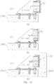
- Figs. 4a) and b) show another preferred embodiment of the guiding device (1) according to the invention further comprising reaction or stop means (9).
- the reaction or stop means (9) are formed by external elements (10), preferably contact plates, which transmit the load perpendicular to the contact plane between the sliding means and the mobile element.
- said external elements (10) that are free from the main body of the guide can be formed by more than one part and/or can be, for example, wedge-shaped.
- said external elements (10) can comprise two wedges that are facing and opposite each other (10'), such that the inclined planes thereof are in contact with each other and the vertical planes thereof are in contact with the mobile element (200) and with the support element (300), respectively.
- Adequately orienting the inclination of the inclined plane in relation to the direction of the relative movement between the mobile element (200) and the support element (300) means that the support element (300) does not prevent said movement, but it does enable load transmission in the direction perpendicular to the contact faces of the reaction means (9) with the mobile element (200) and/or with the support element (300).
- reaction means (9) can be arranged and pressed between the mobile element (200) and the support element (300), adapting to the variations or tolerances of the free distance that separates them.
- the external elements (10) and/or any of the parts thereof can incorporate elements and/or protuberances intended to facilitate the securing thereof to the support element (300) and/or to the mobile element (200) and/or intended to prevent them from falling through the free space between the mobile element (200) or the support element (300).
- Figure 4b shows that this system enables a certain deformation of the means for geometric adaptation (3), starting with a thickness S1 and reducing to S2, such that there is direct contact between the external elements (10) and the mobile element (200), forming a direct contact (11) between rigid and high capacity elements.
- Figure 5 shows another preferred embodiment of the guiding device (1) according to the present invention.
- reaction or stop means (9) comprise a first mortise (12) connected to the securing means and inside of which the means for geometric adaptation (3) are arranged.
- the reaction or stop means (9) further comprise a second mortise (13) connected to the sliding means.
- Said second mortise (13) fits with the first mortise (12) such that relative movement between the sliding means and the securing means is allowed in the direction perpendicular to the sliding surface but prevents it if it is parallel to the sliding surface.
- Fig. 6a shows another preferred embodiment of the guiding device (1) according to the present invention, where the means for geometric adaptation (3) are formed by several elements for geometric adaptation (3').
- the means for geometric adaptation (3) consist of four neoprene cubes (6), installed inside different caissons (13) that act by way of reaction or stop means (9).
- figure 6b shows a certain deformation of the means for geometric adaptation (3) until there is direct contact between the caisson (12) and the sliding means (2), forming direct contact (11) between the rigid and high capacity elements.
- Fig. 7 shows a guiding device (1) according to the present invention comprising means for geometric adaptation (3) formed by a spring-type thrust element (6').
- these means for geometric adaptation (3) can comprise active hydraulic or pneumatic thrust elements.
- Fig. 8 it shows another embodiment of a guiding device (1) according to the present invention.
- the sliding means (2) are formed by a bearing system (5'), preferably formed by a large number of shafts to significantly distribute the load.
- Fig. 9a shows another alternative embodiment of a guiding device (1) according to the present invention.
- the means for geometric adaptation (3) comprise a hydraulic element (3") that allows the distance between the sliding means (2) and the securing means (4) to be regulated.
- Fig. 9b shows another alternative embodiment of a guiding device according to the present invention.
- the means for geometric adaptation (3) comprise a ball joint (3"') that allows a pivoting movement between the sliding means (2) and the securing means (4).
- Figures 10a), b) and c) show a guiding device (1) according to the present invention further comprising means for geometric pre-adjustment or pretensioning (14). These means comprise elements capable of generating a certain level of deformation on the means for geometric adaptation when there is no external load.
- Figure 10a shows the initial position of the assembly method, with the guiding device without adjustments and before coming into contact with the mobile element.
- the means for geometric pre-adjustment (14) are formed by a clamping bolt (15), welded to the sliding means (2). These means for geometric pre-adjustment or pretensioning (14) enable an initial deformation or load to be applied on the device (1), as shown in figure 10b ), such that the thrust in the contact between the device (1) and the mobile element (200) can then be adjusted, as seen in figure 10c ), by means of adjusting or removing the nut of said clamping bolt (15).
- Fig. 11 shows another preferred embodiment of a guiding device (1) according to the present invention where the means for pre-adjustment (14) comprise clamping bolts (15) welded to the sliding means (2) that, in addition to comprising a nut (15') that enables an initial deformation or load to be applied on the device (1), comprise a nut (15") such that the means for pre-adjustment can also create a force on the mobile element in a direction that is essentially perpendicular to the contact surface.
- the means for pre-adjustment comprise clamping bolts (15) welded to the sliding means (2) that, in addition to comprising a nut (15') that enables an initial deformation or load to be applied on the device (1), comprise a nut (15") such that the means for pre-adjustment can also create a force on the mobile element in a direction that is essentially perpendicular to the contact surface.
- the guiding device (1) comprises a space (20) intended to house a hydraulic element, preferably a hydraulic jack that is capable of generating a force on the mobile element in a direction that is essentially perpendicular to the contact surface.
- Fig. 12 shows another preferred embodiment of the guiding device (1) according to the present invention where the securing means (4) comprise bolts (7) secured to bushings (8) embedded in the support element (300) and/or a securing system (7') adapted to the casings (16) in the support element (300).
- the securing means (4) comprise bolts (7) secured to bushings (8) embedded in the support element (300) and/or a securing system (7') adapted to the casings (16) in the support element (300).
- these securing means (4) can also comprise slotted holes (17) to adapt the position of the guiding device (1).
- Fig. 13a shows another preferred embodiment of the guiding device (1) according to the present invention where the support element (300) has a gap to house the device, to improve load transmission between the device and support element.
- FIG. 13b shows a guiding device (1) according to the present invention where the securing means (4) comprise a wedge-shaped double plate (18) to facilitate the removal of the guiding device (1).
- Fig. 14 shows another preferred embodiment of the guiding device (1) according to the present invention where said guiding device can be integrated in a kit and/or assembly that also includes means for hoisting the tower, for example jacks and cables (19).
- the inner section (110') acts as the mobile element (200) in the upper guiding device (1) and as the support element (300) in the lower guiding device (1')
- the outer section (110") acts as the support element (300) in the upper guiding device (1) and as the support element (300) in the lower guiding device (1').
- Fig. 15 shows another preferred embodiment of the guiding device (1) according to the present invention, wherein there are, by way of example but the invention not being limited thereto, means for assisting the sliding (50) that, in this case, comprise Teflon sheets (51) in an endless chain configuration.
- Fig. 16 shows a graph of the behaviour of the guiding device according to the present invention.
- the graph shows a high geometric adjustment capacity at a low load, until there is contact with the reaction or stop means (9).
- the element has a very high load capacity at low deformation.
- the guiding device according to the present invention can similarly be used for assembling the foundation or other elements of the substructure of a wind turbine, preferably those that comprise shafts or vertical walls.
Landscapes
- Engineering & Computer Science (AREA)
- Architecture (AREA)
- Civil Engineering (AREA)
- Structural Engineering (AREA)
- Life Sciences & Earth Sciences (AREA)
- General Engineering & Computer Science (AREA)
- Sustainable Energy (AREA)
- Chemical & Material Sciences (AREA)
- Combustion & Propulsion (AREA)
- Mechanical Engineering (AREA)
- Sustainable Development (AREA)
- General Life Sciences & Earth Sciences (AREA)
- Mining & Mineral Resources (AREA)
- Paleontology (AREA)
- Wind Motors (AREA)
Abstract
Description
- The present invention relates to a guiding device for assembling towers and/or foundations for wind turbines, essentially for hoisting and/or anchoring wind turbine towers, for example concrete telescopic towers, both onshore and offshore.
- Therefore, the main application sector of the present invention is the construction industry, especially in assembling towers, in combination with the renewable or green energy industry, specifically wind energy.
- The use of guiding devices to carry out the relative movement between two adjacent and/or concentric structures, or elements of a structure, is widely known.
- Similarly, different means and/or systems for assembling structures are known, more specifically means for hoisting adjacent and/or concentric structures, either in the field of general structures, for example general high-rise structures, or in the more specific field of wind energy, especially in the field of wind turbine towers.
- For example, the document
FR 2587399 - Similarly, document
RU 2189935 C2 - Furthermore, the documents
EP 0201645 A2 orFR 2476727 A2 - However, as can be seen, none of the hoisting systems describes a guiding device such as the one described in the present invention, which resolves the significant problems existing in the field of the current state of the art, since it is capable of supporting very high loads, that at the same time has a high adaptation capacity to adapt to geometric variations or imperfections in the elements to be guided, and that entails great advantages with respect to those described above.
- The present invention aims to provide a guiding device for assembling towers and/or foundations for wind turbines, which can be onshore and/or offshore, and especially for telescopic wind turbine towers, such that the assembly process of said structures is facilitated and optimised. For the purposes of the present invention, it is understood that the shaft of a wind turbine tower can be considered to be part of the foundation of the same.
- Another aim of the present invention is to provide a guiding device that allows relative sliding between a mobile element of the wind turbine tower and a support element, which can comprise, for example but not limited to the present invention, two sections of the shaft of the wind turbine tower and/or a section thereof and an auxiliary structure, and which allows said sliding whilst being able to adapt the geometry thereof depending on the geometric or other imperfections that may exist in said section, especially if it is a concrete section, where the tolerances and variations are greater than in metal sections.
- The guiding device according to the present invention is more efficient than those described above since it has particular characteristics that contribute new advantages to the hoisting and/or anchoring of a wind turbine tower, such as the capacity to withstand large loads while at the same time providing a large geometric adaptation capacity.
- To do so, the present invention proposes a guiding device for towers and/or foundations for wind turbines intended to allow relative sliding and/or movement between a mobile element and a support element, and which comprises:
- a) Sliding means that are in contact with the mobile element and allow the relative movement thereof with respect to the guiding device.
- b) Securing means that connect the guiding device to the support element.
- c) Means for geometric adaptation disposed between the sliding means and the securing means, which allow load transmission between the sliding means and the securing means while at the same time also allowing relative movement between the two.
- d) Reaction or stop means, preferably by way of mortises and/or contact plates, arranged such that they enable direct load transmission between the sliding means and the securing means.
- The guiding device according to the present invention can further comprise:
- e) Means for geometric pre-adjustment or pretensioning; and/or
- f) Means for assisting the sliding of the element or structure.
- The sliding means of the guiding device according to the present invention can comprise a bearing surface and/or system that is in contact with a section of the wind turbine tower, preferably the mobile element, intended to reduce fiction with the sliding element.
- Likewise, the means for geometric adaptation described in the guiding device according to the present invention can be formed by one or several elements for geometric adaptation, preferably neoprene, either fitted or not, or a similar, rubber type, elastomer material with suitable deformability characteristics known in the state of the art.
- Similarly, the means for geometric adaptation of the guiding device according to the present invention can comprise one or several, preferably elastic, elements in the shape of parts or springs, and/or one or several hydraulic and/or pneumatic elements that can enable active control of the force and/or deformation of the guiding device and, as a result, capable of regulating the distance between the sliding means and the securing means.
- Without limiting the scope of the present invention, the reaction or stop means of the guiding device according to the present invention can be based on mortise-shaped elements and/or independent elements, in another plan position, or in the geometry itself of the elements, which in any case only start to act as of a certain level of deformation of the guiding device, such that both the mortise-shaped elements and the independent elements allow direct load transmission between the sliding means and the securing means.
- These reaction or stop means can transmit the loads in a direction that is essentially perpendicular to the contact plane of the guiding device with the mobile element and/or the forces parallel to the plane of the sliding surface only as of a certain level of deformation of the means for geometric adaptation and/or certain relative movement between the securing means and the sliding means, for example with interlocking mortises between the securing means and the sliding means.
- Preferably, the means for geometric adaptation are arranged inside mortises by way of a piston.
- As for the means for geometric pre-adjustment or pretensioning, they can be defined, for example, by one or several clamping bolts that enable the initial precompression of the means for geometric adaptation, or by any other means known in the state of the art that enables a certain deformation to be generated in the means for geometric adaptation when there are no other loads acting thereon, as well as generating a force on the mobile element in a direction that is essentially perpendicular to the contact surface. These means for geometric pre-adjustment can be used, for example, to generate a certain initial contact force between the sliding means and the mobile element, or to cancel or reduce said force in order to retrieve the guiding device.
- Similarly, the securing and/or fastening means comprise at least one metal element, preferably at least one bolt, which is fastened to the support element. In a particular case, but the invention not being limited thereto, the guiding device described in the present invention can also comprise securing and/or fastening means that use the existing casings for the pretensioning bars and/or cables.
- Similarly, but the invention not being limited thereto, the guiding device according to the present invention can be integrated in a kit and/or assembly that also includes means for hoisting the tower.
- The guiding device, object of the present invention, can comprise means for assisting the sliding of the elements or structures, whether by means of greases or other fluids that reduce friction between elements. Interspersed sheets made of low friction materials such as Teflon or other methods known in the state of the art can also be used.
- Lastly, the guiding device described in the present invention can be completely or partially recoverable and reusable for more than one phase of the assembly method for the wind turbine tower and/or for assembling more than one wind turbine tower, this possibly being modular, such that some means or others can be disassembled and/or replaced.
- The guiding device according to the present invention allows relative movement between a support element and a mobile element, regardless of the absolute movements of said elements, one possibly being mobile and the other fixed, or both being mobile.
- The previous advantages and characteristics, in addition to others, shall be understood more fully in light of the following detailed description of exemplary embodiments, with reference to the drawings attached, which must be taken by way of illustration and not limitation, wherein:
-
Fig. 1 a) shows an elevation view of the position of the guiding devices when hoisting a telescopic tower. -
Fig. 1 b) shows a plan view of the position of the guiding devices when hoisting a telescopic tower. -
Fig. 2 shows several phases of the anchoring of an offshore tower along with the position of the guiding devices at all times. -
Fig. 3 shows a basic guiding device according to the invention. -
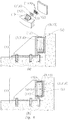
Fig. 4a ) shows a guiding device according to the invention comprising independent reaction or stop elements. -
Fig. 4b ) shows a guiding device according to the invention in the position in which the reaction or stop means start to act. -
Fig. 4c ) shows an embodiment of the invention where the reaction or stop means comprise external elements, based on two wedges that are facing and opposite each other. -
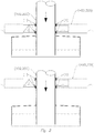
Fig. 5 shows a guiding device according to the invention comprising reaction or stop means in the form of mortises. -
Fig. 6a ) shows a guiding device according to the present invention comprising several elements for geometric adaptation. -
Fig. 6b ) shows a guiding device according to the present invention comprising several elements for geometric adaptation and in the position in which the reaction or stop means start to act. -
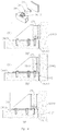
Fig. 7 shows a guiding device according to the present invention with a variation with respect to the means for geometric adaptation. -
Fig. 8 shows a guiding device according to the present invention with a variation with respect to the sliding means. -
Fig. 9a ) shows a guiding device according to an alternative embodiment of the present invention comprising first means for geometric adjustment. -
Fig. 9b ) shows a guiding device according to an alternative embodiment of the present invention comprising second means for geometric adjustment. -
Fig. 10a ) shows a guiding device according to the present invention comprising means for geometric pre-adjustment or pretensioning in an initial position. -
Fig. 10b ) shows a guiding device according to the present invention that is pretensed by means of the means for geometric pre-adjustment or pretensioning. -
Fig. 10c ) shows a guiding device according to the present invention comprising means for geometric pre-adjustment or pretensioning during the movement of the elements. -
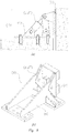
Fig. 11 shows a guiding device according to the present invention comprising means for geometric pre-adjustment or pretensioning capable of exerting a force of the mobile element. -
Fig. 12 shows a guiding device according to the present invention comprising alternative securing and/or fastening means to the support element. -
Fig. 13 shows a guiding device according to the present invention where the support element has a gap to house said device. -
Fig. 14 shows a guiding device according to the present invention that is integrated in a kit and/or assembly that includes means for hoisting the tower. -
Fig. 15 shows a guiding device according to the present invention with a Teflon sheet in an endless chain configuration. -
Fig. 16 shows a graph of the behaviour of the guiding device depending on the force applied. -
Fig. 1 a) shows an elevation view of the position of the guiding devices (1, 1') during the assembly of a wind turbine tower (100), which is offshore in this case. - This case shows, by way of example, the hoisting of a wind turbine tower (100), and specifically, the hoisting of a telescopic tower (101), made up of different sections (110).
- Preferably, the guiding devices (1) are arranged in the two elements or structures (110', 110") that are involved in the movement, but they can also be solely located in one of said elements or structures (110', 110").
- Moreover, in this embodiment, in the case of guiding devices (1), the section of telescopic tower (110') acts as a mobile element (200) and the section (110") acts as a support element (300), while in the guiding devices (1'), the section (110') acts as a support element (200) and the section (110") acts as a mobile element (300).
- Preferably, the guiding elements (1, 1') are arranged in the upper and/or lower portion of the elements or structures (110', 110"), but they can also be arranged on the side faces of the elements or structures (110', 110"), being in the middle thereof.
-
Fig. 1 b) shows a plan view of the position of the guiding devices (1) during the assembly of a wind turbine tower (100). - This case shows, by way of example, the hoisting of a wind turbine tower (100), and specifically, the hoisting of a telescopic tower (101).
- Preferably, there are three or more devices (1, 1') for the hoisting and/or anchoring of a wind turbine tower (100). In this embodiment, there are six devices (1) on the plane for hoisting the different sections (110) of the tower.
-
Fig. 2 shows several phases of the anchoring of an offshore tower (102). In this embodiment, the guiding devices (1) are located in an auxiliary floating and/or stability device (400) such that the tower (102) can slide through the inside thereof during its anchoring. In this particular case, the tower (102) acts as the mobile element (200), while the structure (400) acts as the support element (300). -
Fig. 3 shows a guiding device (1) according to the present invention comprising sliding means (2), means for geometric adaptation (3) and securing means (4). - In this embodiment, the guiding device (1) is fastened to the upper portion of the support element (300), while the latter is in contact with the mobile element (200) by means of the sliding means (2).
- By way of example, but the invention not being limited thereto, the sliding means (2) comprise a surface or pad with a low friction coefficient (5) and the means for geometric adaptation (3) are formed by a neoprene part (6).
- The guiding device (1) is fastened to the support element (300) by means of the securing means (4) that in this case comprise, but the invention not being limited thereto, bolts (7) secured to bushings (8) embedded in the support element (300) itself.
- Similarly, the guide device (1) according to the present invention can comprise means for assisting the sliding (50) which can consist of greases or other fluids that facilitate the sliding between the mobile element (200) and the sliding means (2), by means of reducing the friction between the two. Interspersed sheets made of low friction materials such as Teflon or other methods known in the state of the art can also be used, for example, placed in an endless chain configuration.
-
Figs. 4a) and b) show another preferred embodiment of the guiding device (1) according to the invention further comprising reaction or stop means (9). In this embodiment, the reaction or stop means (9) are formed by external elements (10), preferably contact plates, which transmit the load perpendicular to the contact plane between the sliding means and the mobile element. In one embodiment of the invention, said external elements (10) that are free from the main body of the guide can be formed by more than one part and/or can be, for example, wedge-shaped. In particular, according to that which is shown inFig. 4c) , said external elements (10) can comprise two wedges that are facing and opposite each other (10'), such that the inclined planes thereof are in contact with each other and the vertical planes thereof are in contact with the mobile element (200) and with the support element (300), respectively. Adequately orienting the inclination of the inclined plane in relation to the direction of the relative movement between the mobile element (200) and the support element (300) means that the support element (300) does not prevent said movement, but it does enable load transmission in the direction perpendicular to the contact faces of the reaction means (9) with the mobile element (200) and/or with the support element (300). Similarly, it means that said reaction means (9) can be arranged and pressed between the mobile element (200) and the support element (300), adapting to the variations or tolerances of the free distance that separates them. The external elements (10) and/or any of the parts thereof can incorporate elements and/or protuberances intended to facilitate the securing thereof to the support element (300) and/or to the mobile element (200) and/or intended to prevent them from falling through the free space between the mobile element (200) or the support element (300). -
Figure 4b ) shows that this system enables a certain deformation of the means for geometric adaptation (3), starting with a thickness S1 and reducing to S2, such that there is direct contact between the external elements (10) and the mobile element (200), forming a direct contact (11) between rigid and high capacity elements. -
Figure 5 shows another preferred embodiment of the guiding device (1) according to the present invention. - In this embodiment, the reaction or stop means (9) comprise a first mortise (12) connected to the securing means and inside of which the means for geometric adaptation (3) are arranged.
- The reaction or stop means (9) further comprise a second mortise (13) connected to the sliding means. Said second mortise (13) fits with the first mortise (12) such that relative movement between the sliding means and the securing means is allowed in the direction perpendicular to the sliding surface but prevents it if it is parallel to the sliding surface.
- In this way, the movement of the means for geometric adaptation (3) is allowed in the direction (A), while the movement is prevented in direction (B).
-
Fig. 6a ) shows another preferred embodiment of the guiding device (1) according to the present invention, where the means for geometric adaptation (3) are formed by several elements for geometric adaptation (3'). In this case, but the invention not being limited thereto, the means for geometric adaptation (3) consist of four neoprene cubes (6), installed inside different caissons (13) that act by way of reaction or stop means (9). - Similarly to
figure 4b ),figure 6b ) shows a certain deformation of the means for geometric adaptation (3) until there is direct contact between the caisson (12) and the sliding means (2), forming direct contact (11) between the rigid and high capacity elements. -
Fig. 7 shows a guiding device (1) according to the present invention comprising means for geometric adaptation (3) formed by a spring-type thrust element (6'). Similarly, these means for geometric adaptation (3) can comprise active hydraulic or pneumatic thrust elements. - As for
Fig. 8 , it shows another embodiment of a guiding device (1) according to the present invention. In this case, the sliding means (2) are formed by a bearing system (5'), preferably formed by a large number of shafts to significantly distribute the load. -
Fig. 9a ) shows another alternative embodiment of a guiding device (1) according to the present invention. In this case, the means for geometric adaptation (3) comprise a hydraulic element (3") that allows the distance between the sliding means (2) and the securing means (4) to be regulated. -
Fig. 9b ) shows another alternative embodiment of a guiding device according to the present invention. In this case, the means for geometric adaptation (3) comprise a ball joint (3"') that allows a pivoting movement between the sliding means (2) and the securing means (4). -
Figures 10a), b) and c) show a guiding device (1) according to the present invention further comprising means for geometric pre-adjustment or pretensioning (14). These means comprise elements capable of generating a certain level of deformation on the means for geometric adaptation when there is no external load. -
Figure 10a ) shows the initial position of the assembly method, with the guiding device without adjustments and before coming into contact with the mobile element. - In this embodiment, by way of example but the invention not being limited thereto, the means for geometric pre-adjustment (14) are formed by a clamping bolt (15), welded to the sliding means (2). These means for geometric pre-adjustment or pretensioning (14) enable an initial deformation or load to be applied on the device (1), as shown in
figure 10b ), such that the thrust in the contact between the device (1) and the mobile element (200) can then be adjusted, as seen infigure 10c ), by means of adjusting or removing the nut of said clamping bolt (15). - These means for geometric pre-adjustment can also be used to separate the sliding means (2) and the mobile element (200) in order to remove the device (1).
-
Fig. 11 shows another preferred embodiment of a guiding device (1) according to the present invention where the means for pre-adjustment (14) comprise clamping bolts (15) welded to the sliding means (2) that, in addition to comprising a nut (15') that enables an initial deformation or load to be applied on the device (1), comprise a nut (15") such that the means for pre-adjustment can also create a force on the mobile element in a direction that is essentially perpendicular to the contact surface. - Moreover, in this embodiment, the guiding device (1) comprises a space (20) intended to house a hydraulic element, preferably a hydraulic jack that is capable of generating a force on the mobile element in a direction that is essentially perpendicular to the contact surface.
-
Fig. 12 shows another preferred embodiment of the guiding device (1) according to the present invention where the securing means (4) comprise bolts (7) secured to bushings (8) embedded in the support element (300) and/or a securing system (7') adapted to the casings (16) in the support element (300). - Likewise, these securing means (4) can also comprise slotted holes (17) to adapt the position of the guiding device (1).
-
Fig. 13a ) shows another preferred embodiment of the guiding device (1) according to the present invention where the support element (300) has a gap to house the device, to improve load transmission between the device and support element. - In this case,
Fig. 13b ) shows a guiding device (1) according to the present invention where the securing means (4) comprise a wedge-shaped double plate (18) to facilitate the removal of the guiding device (1). -
Fig. 14 shows another preferred embodiment of the guiding device (1) according to the present invention where said guiding device can be integrated in a kit and/or assembly that also includes means for hoisting the tower, for example jacks and cables (19). In this embodiment, it can be seen that the inner section (110') acts as the mobile element (200) in the upper guiding device (1) and as the support element (300) in the lower guiding device (1'), while the outer section (110") acts as the support element (300) in the upper guiding device (1) and as the support element (300) in the lower guiding device (1'). -
Fig. 15 shows another preferred embodiment of the guiding device (1) according to the present invention, wherein there are, by way of example but the invention not being limited thereto, means for assisting the sliding (50) that, in this case, comprise Teflon sheets (51) in an endless chain configuration. -
Fig. 16 shows a graph of the behaviour of the guiding device according to the present invention. The graph shows a high geometric adjustment capacity at a low load, until there is contact with the reaction or stop means (9). As of this point, the element has a very high load capacity at low deformation. - Although the figures and above explanations particularly refer to the assembly of wind turbine towers, the guiding device according to the present invention can similarly be used for assembling the foundation or other elements of the substructure of a wind turbine, preferably those that comprise shafts or vertical walls.
Claims (17)
- A guiding device (1) for assembling towers and/or foundations for wind turbines, intended to enable and/or facilitate relative movement between a mobile element (200) and a support element (300), at least one of said elements (200, 300) being a section and/or part of the shaft of a wind turbine tower or foundation (100) characterised in that it comprises:- sliding means (2) that are in contact with the mobile element (200) and allow the relative movement thereof with respect to the guiding device (1);- securing means (4) that connect the guiding device (1) to the support element (300);- means for geometric adaptation (3) disposed between the sliding means (2) and the securing means (4), which allow load transmission between the sliding means and the securing means while at the same time also allowing relative movement between the two;- reaction or stop means (9) by way of mortises and/or contact plates that enable direct load transmission between the sliding means (2) and the securing means (4).
- The guiding device (1) according to the preceding claim, characterized in that the means for geometric adaptation (3) are arranged inside the mortises by way of a piston (3") that only allows relative movement between the sliding means (2) and the securing means (4) in a direction that is essentially perpendicular to the contact plane between the guiding device (1) and the mobile element (200).
- The guiding device (1) according to any of the preceding claims, characterised in that the sliding means (2) comprise a low friction surface (50) in contact with the mobile element (200) and/or a bearing system (5') in contact with the mobile element (200).
- The guiding device (1) according to any on the preceding claims, characterised in that the means for geometric adaptation (3) comprise a deformable and essentially elastic element (6') in the form of a part or spring.
- The guiding device (1) according to any of the preceding claims, characterised in that the means for geometric adaptation (3) comprise a hydraulic or pneumatic element (3") that allows the distance between the sliding means (2) and the securing means (4) to be regulated.
- The guiding device (1) according to any of the preceding claims, characterised in that the securing means (4) comprise a metal element fastened to the support element (300).
- The guiding device (1) according any of the preceding claims, characterised in that the reaction or stop means (9) are arranged such that they allow load transmission in a direction that is essentially perpendicular to the contact plane of the guiding device (1) with the mobile element (200), only as of a certain level of deformation of the means for geometric adaptation (3) and/or certain relative movement between the securing means (4) and the sliding means (2).
- The guiding device (1) according to any of the preceding claims, characterised in that it comprises means for pre-adjustment (14) of the geometry of the means for geometric adaptation (3), arranged such that they generate a certain level of deformation on the means for geometric adaptation (3) when there is no external load.
- The guiding device (1) according to the preceding claim, characterised in that the means for pre-adjustment (14) can also generate a force on the mobile element (200) in a direction that is essentially perpendicular to the contact surface.
- The guiding device (1) according to any of the preceding claims, characterised in that it comprises a space (20) intended to house a hydraulic element (3") that is capable of generating a force on the mobile element (200) in a direction that is essentially perpendicular to the contact surface.
- The guiding device (1) according to any of the preceding claims, characterised in that it is completely or partially recoverable and/or reusable for more than one phase of the assembly method of the wind turbine tower (100) and/or for assembling more than one wind turbine tower (100).
- The guiding device (1) according to any of the preceding claims, characterised in that it comprises reaction or stop means (9) formed by external elements (10) interposed between the mobile element (200) and the support element (300), and in that said external elements (10) comprise two parts facing each other and wedge-shaped.
- The guiding device (1) according to any of the preceding claims, characterised in that the means for geometric adaptation (3) comprise a ball joint (3"') that allows a pivoting movement between the sliding means (2) and the securing means (4).
- A kit for wind turbine towers (100) that comprises a guiding device (1) according to any of the preceding claims and at least one means for hoisting (19) wind turbine towers (100).
- An assembly method of a wind turbine tower (100) and/or a foundation for a wind turbine tower (100) characterised in that it comprises the steps:a) hoisting a section of tower (110) assisted by a guiding device (1) according to any of claims 1-13; and/orb) anchoring or sinking a foundation and/or tower (100) assisted by a guiding device (1) according to any of claims 1-13.
- A wind turbine tower or foundation (100) assembled with an assembly method according to the preceding claim.
- A wind turbine supported on a wind turbine tower or foundation (100) according to the preceding claim.
Priority Applications (1)
| Application Number | Priority Date | Filing Date | Title |
|---|---|---|---|
| PL16848190T PL3354894T3 (en) | 2015-09-23 | 2016-09-20 | Guiding device for assembling wind turbine towers |
Applications Claiming Priority (2)
| Application Number | Priority Date | Filing Date | Title |
|---|---|---|---|
| ES201531355A ES2606786B1 (en) | 2015-09-23 | 2015-09-23 | GUIDE DEVICE FOR WINDOW TOWER ASSEMBLY |
| PCT/ES2016/070653 WO2017051048A1 (en) | 2015-09-23 | 2016-09-20 | Guiding device for assembling wind turbine towers |
Publications (3)
| Publication Number | Publication Date |
|---|---|
| EP3354894A1 true EP3354894A1 (en) | 2018-08-01 |
| EP3354894A4 EP3354894A4 (en) | 2019-06-26 |
| EP3354894B1 EP3354894B1 (en) | 2020-11-04 |
Family
ID=58386132
Family Applications (1)
| Application Number | Title | Priority Date | Filing Date |
|---|---|---|---|
| EP16848190.1A Active EP3354894B1 (en) | 2015-09-23 | 2016-09-20 | Guiding device for assembling wind turbine towers |
Country Status (7)
| Country | Link |
|---|---|
| US (1) | US10669736B2 (en) |
| EP (1) | EP3354894B1 (en) |
| CN (1) | CN108350859B (en) |
| ES (1) | ES2606786B1 (en) |
| PL (1) | PL3354894T3 (en) |
| PT (1) | PT3354894T (en) |
| WO (1) | WO2017051048A1 (en) |
Families Citing this family (7)
| Publication number | Priority date | Publication date | Assignee | Title |
|---|---|---|---|---|
| US10544559B2 (en) * | 2016-11-02 | 2020-01-28 | Inventus Holdings, Llc | Pier and mat foundation fortification and monitoring system |
| ES2728789B2 (en) * | 2018-04-25 | 2020-03-03 | Esteyco S A | MOBILE MODULE FOR LIFTING TELESCOPIC TOWERS AND LIFTING PROCEDURE FOR TELESCOPIC TOWERS |
| US10822764B2 (en) * | 2019-02-21 | 2020-11-03 | General Electric Company | Method of connecting a tower to a foundation |
| AT522250A1 (en) * | 2019-02-28 | 2020-09-15 | Holcim Technology Ltd | Foundation for a wind turbine |
| ES2785802B2 (en) * | 2019-04-05 | 2021-05-19 | Esteyco S A | INSTALLATION PROCEDURE FOR A TORRE MAR INTO WIND GENERATOR |
| CN113638853B (en) * | 2021-09-18 | 2022-11-15 | 北京云庐科技有限公司 | Monitoring system for the lifting process of self-elevating wind power tower |
| WO2023094851A1 (en) * | 2021-11-23 | 2023-06-01 | Nabrawind Technologies, S.L. | System for the automated lifting of a hybrid-tower wind turbine and method followed |
Family Cites Families (22)
| Publication number | Priority date | Publication date | Assignee | Title |
|---|---|---|---|---|
| FR2188758A5 (en) * | 1972-06-12 | 1974-01-18 | Michel Lucien | |
| FR2476727A2 (en) | 1979-07-30 | 1981-08-28 | Icpp | Automatically raised mobile pylon on trailer - has battery operated hydraulic pump providing fluid pressure in jack to raise telescopic sections |
| US4327534A (en) * | 1980-06-26 | 1982-05-04 | A. B. Chance Company | Method and apparatus for extending the height of utility poles |
| FR2587399B1 (en) | 1985-02-04 | 1988-01-08 | Desmoinaux Ind Sa | SELF-LIFTING PYLON COMPRISING IMPROVED GUIDANCE MEANS OF ITS CONSTITUENT ELEMENTS |
| DE3585444D1 (en) | 1985-05-10 | 1992-04-02 | Chu Associates | COMPOSITION OF A LIGHT TELESCOPIC ANTENNA POLE OR THE LIKE. |
| GB2217215B (en) * | 1988-04-09 | 1992-02-12 | Michael Headlam Purser | Arrangement including a moveable tower |
| US4932176A (en) * | 1988-09-19 | 1990-06-12 | Gte Government Systems Corporation | Extendible and retractible mast system |
| DE4337601A1 (en) * | 1993-11-01 | 1995-05-04 | Mannesmann Ag | Telescopic column |
| FR2757497B1 (en) | 1996-12-23 | 1999-02-12 | Potain Sa | TELESCOPIC MATURE FOR TOWER CRANE |
| US7114690B2 (en) * | 2001-02-21 | 2006-10-03 | Schwing America, Inc. | Universal mast support frame and method for mounting masts |
| DK200200178A (en) * | 2002-02-06 | 2003-08-07 | Vestas Wind Sys As | Wind turbine tower suspension means |
| US7666103B2 (en) * | 2004-01-29 | 2010-02-23 | Cottingham Agencies Ltd. | Amusement ride |
| WO2010059489A1 (en) * | 2008-11-19 | 2010-05-27 | Sydney Belinsky | Stationary positioned offshore windpower plant (owp) and methods and means for its assembly, transportation, installation and servicing |
| CA2770886C (en) * | 2009-09-09 | 2014-07-08 | National Oilwell Varco, L.P. | Method and apparatus for wind turbine erection |
| IT1396433B1 (en) * | 2009-11-16 | 2012-11-23 | Rolic Invest Sarl | WIND POWER PLANT FOR THE GENERATION OF ELECTRICITY AND METHOD TO REALIZE A PILONE OF THE ABOVE WIND FACILITY. |
| ES2595231T3 (en) * | 2010-04-06 | 2016-12-28 | Soletanche Freyssinet | Hybrid tower construction method for a wind generator |
| WO2013029626A1 (en) * | 2011-08-30 | 2013-03-07 | Vestas Wind Systems A/S | Transition structure for a wind turbine tower |
| ES2407779B1 (en) * | 2011-12-09 | 2014-09-02 | Esteyco Energía S.L. | ASSEMBLY PROCEDURE OF A TELESCOPIC TOWER AND MEANS TO IMPLEMENT SUCH PROCEDURE |
| ES2407756B1 (en) * | 2011-12-09 | 2014-06-10 | Esteyco Energía S.L. | ASSEMBLY PROCEDURE OF A TELESCOPIC TOWER |
| US9297159B2 (en) * | 2013-09-10 | 2016-03-29 | Bruce William Darden | Power lock system for stage truss towers |
| US9458974B2 (en) * | 2014-06-08 | 2016-10-04 | Robert E. Townsend, Jr. | Flexible moment connection device for mast arm signal mounting |
| US9556636B2 (en) * | 2014-06-27 | 2017-01-31 | Tindall Corporation | Method and apparatus for erecting tower with hydraulic cylinders |
-
2015
- 2015-09-23 ES ES201531355A patent/ES2606786B1/en active Active
-
2016
- 2016-09-20 US US15/762,977 patent/US10669736B2/en active Active
- 2016-09-20 CN CN201680066380.6A patent/CN108350859B/en active Active
- 2016-09-20 PL PL16848190T patent/PL3354894T3/en unknown
- 2016-09-20 EP EP16848190.1A patent/EP3354894B1/en active Active
- 2016-09-20 WO PCT/ES2016/070653 patent/WO2017051048A1/en not_active Ceased
- 2016-09-20 PT PT168481901T patent/PT3354894T/en unknown
Also Published As
| Publication number | Publication date |
|---|---|
| EP3354894B1 (en) | 2020-11-04 |
| US20190085583A1 (en) | 2019-03-21 |
| EP3354894A4 (en) | 2019-06-26 |
| PT3354894T (en) | 2021-02-09 |
| ES2606786A1 (en) | 2017-03-27 |
| ES2606786B1 (en) | 2018-01-31 |
| CN108350859B (en) | 2020-01-31 |
| CN108350859A (en) | 2018-07-31 |
| US10669736B2 (en) | 2020-06-02 |
| WO2017051048A1 (en) | 2017-03-30 |
| PL3354894T3 (en) | 2021-08-02 |
Similar Documents
| Publication | Publication Date | Title |
|---|---|---|
| EP3354894B1 (en) | Guiding device for assembling wind turbine towers | |
| EP2910686B1 (en) | In-line connection for an offshore onstruction; offshore construction; method for installing | |
| EP3130796B1 (en) | Wind turbine assembly system and related method | |
| EP3631202B1 (en) | Wind turbine tower reinforcement system | |
| KR100948359B1 (en) | The bridge upper structure lifting method for which bridge upper structure lifter which does the bridge shue function and this were used | |
| EP3227512B1 (en) | Section of concrete | |
| EP3161219B1 (en) | A structure and a method for erecting tower with hydraulic cylinders | |
| CN101809283A (en) | Monopile foundation for offshore wind turbine | |
| EP2662495B1 (en) | Wind turbine foundation | |
| JP4701047B2 (en) | Wind power tower construction method | |
| US20180148921A1 (en) | Resilient bearing | |
| GB2425329A (en) | Arrangement for supporting turbine installation | |
| KR101030747B1 (en) | Anchor for easy maintenance | |
| US4721417A (en) | Compliant offshore structure stabilized by resilient pile assemblies | |
| US12442207B2 (en) | Reinforcement of wind turbine structures | |
| KR102045025B1 (en) | Roundness Maintaining Device of Large Cylindrical Structure and Manufacturing Method Thereof | |
| KR20180033117A (en) | Apparatus and method for infrastructure installation | |
| DK2785921T3 (en) | Embedded cylindrical connection, which uses supporting surfaces for offshore single-pile foundations | |
| EP2374992A1 (en) | A support device | |
| JP5002045B2 (en) | Building basic structure | |
| EP3246471B1 (en) | Device and method for connecting a hollow tubular structure in erected state to a work of a floating device | |
| EP3168390B1 (en) | Structure for a wind turbine tower | |
| EP2743404B1 (en) | Method for constructing an offshore structure | |
| CN209276908U (en) | It is a kind of that high-power transformer construction and installation and maintenance is facilitated to tear the track foundation equipment of shifting open | |
| CN223688804U (en) | Temporary supporting device for movable bridge girder body |
Legal Events
| Date | Code | Title | Description |
|---|---|---|---|
| STAA | Information on the status of an ep patent application or granted ep patent |
Free format text: STATUS: THE INTERNATIONAL PUBLICATION HAS BEEN MADE |
|
| PUAI | Public reference made under article 153(3) epc to a published international application that has entered the european phase |
Free format text: ORIGINAL CODE: 0009012 |
|
| STAA | Information on the status of an ep patent application or granted ep patent |
Free format text: STATUS: REQUEST FOR EXAMINATION WAS MADE |
|
| 17P | Request for examination filed |
Effective date: 20180415 |
|
| AK | Designated contracting states |
Kind code of ref document: A1 Designated state(s): AL AT BE BG CH CY CZ DE DK EE ES FI FR GB GR HR HU IE IS IT LI LT LU LV MC MK MT NL NO PL PT RO RS SE SI SK SM TR |
|
| AX | Request for extension of the european patent |
Extension state: BA ME |
|
| DAV | Request for validation of the european patent (deleted) | ||
| DAX | Request for extension of the european patent (deleted) | ||
| A4 | Supplementary search report drawn up and despatched |
Effective date: 20190527 |
|
| RIC1 | Information provided on ipc code assigned before grant |
Ipc: F03D 1/00 20060101AFI20190521BHEP Ipc: E04H 12/18 20060101ALI20190521BHEP |
|
| RAP1 | Party data changed (applicant data changed or rights of an application transferred) |
Owner name: ESTEYCO SA |
|
| GRAP | Despatch of communication of intention to grant a patent |
Free format text: ORIGINAL CODE: EPIDOSNIGR1 |
|
| STAA | Information on the status of an ep patent application or granted ep patent |
Free format text: STATUS: GRANT OF PATENT IS INTENDED |
|
| INTG | Intention to grant announced |
Effective date: 20200528 |
|
| GRAS | Grant fee paid |
Free format text: ORIGINAL CODE: EPIDOSNIGR3 |
|
| GRAA | (expected) grant |
Free format text: ORIGINAL CODE: 0009210 |
|
| STAA | Information on the status of an ep patent application or granted ep patent |
Free format text: STATUS: THE PATENT HAS BEEN GRANTED |
|
| AK | Designated contracting states |
Kind code of ref document: B1 Designated state(s): AL AT BE BG CH CY CZ DE DK EE ES FI FR GB GR HR HU IE IS IT LI LT LU LV MC MK MT NL NO PL PT RO RS SE SI SK SM TR |
|
| REG | Reference to a national code |
Ref country code: GB Ref legal event code: FG4D |
|
| REG | Reference to a national code |
Ref country code: CH Ref legal event code: EP |
|
| REG | Reference to a national code |
Ref country code: AT Ref legal event code: REF Ref document number: 1331132 Country of ref document: AT Kind code of ref document: T Effective date: 20201115 |
|
| REG | Reference to a national code |
Ref country code: DE Ref legal event code: R096 Ref document number: 602016047412 Country of ref document: DE |
|
| REG | Reference to a national code |
Ref country code: IE Ref legal event code: FG4D |
|
| REG | Reference to a national code |
Ref country code: NL Ref legal event code: FP |
|
| REG | Reference to a national code |
Ref country code: PT Ref legal event code: SC4A Ref document number: 3354894 Country of ref document: PT Date of ref document: 20210209 Kind code of ref document: T Free format text: AVAILABILITY OF NATIONAL TRANSLATION Effective date: 20210202 |
|
| REG | Reference to a national code |
Ref country code: SE Ref legal event code: TRGR |
|
| REG | Reference to a national code |
Ref country code: AT Ref legal event code: MK05 Ref document number: 1331132 Country of ref document: AT Kind code of ref document: T Effective date: 20201104 |
|
| PG25 | Lapsed in a contracting state [announced via postgrant information from national office to epo] |
Ref country code: RS Free format text: LAPSE BECAUSE OF FAILURE TO SUBMIT A TRANSLATION OF THE DESCRIPTION OR TO PAY THE FEE WITHIN THE PRESCRIBED TIME-LIMIT Effective date: 20201104 Ref country code: NO Free format text: LAPSE BECAUSE OF FAILURE TO SUBMIT A TRANSLATION OF THE DESCRIPTION OR TO PAY THE FEE WITHIN THE PRESCRIBED TIME-LIMIT Effective date: 20210204 Ref country code: FI Free format text: LAPSE BECAUSE OF FAILURE TO SUBMIT A TRANSLATION OF THE DESCRIPTION OR TO PAY THE FEE WITHIN THE PRESCRIBED TIME-LIMIT Effective date: 20201104 Ref country code: GR Free format text: LAPSE BECAUSE OF FAILURE TO SUBMIT A TRANSLATION OF THE DESCRIPTION OR TO PAY THE FEE WITHIN THE PRESCRIBED TIME-LIMIT Effective date: 20210205 |
|
| PG25 | Lapsed in a contracting state [announced via postgrant information from national office to epo] |
Ref country code: AT Free format text: LAPSE BECAUSE OF FAILURE TO SUBMIT A TRANSLATION OF THE DESCRIPTION OR TO PAY THE FEE WITHIN THE PRESCRIBED TIME-LIMIT Effective date: 20201104 Ref country code: ES Free format text: LAPSE BECAUSE OF FAILURE TO SUBMIT A TRANSLATION OF THE DESCRIPTION OR TO PAY THE FEE WITHIN THE PRESCRIBED TIME-LIMIT Effective date: 20201104 Ref country code: IS Free format text: LAPSE BECAUSE OF FAILURE TO SUBMIT A TRANSLATION OF THE DESCRIPTION OR TO PAY THE FEE WITHIN THE PRESCRIBED TIME-LIMIT Effective date: 20210304 Ref country code: LV Free format text: LAPSE BECAUSE OF FAILURE TO SUBMIT A TRANSLATION OF THE DESCRIPTION OR TO PAY THE FEE WITHIN THE PRESCRIBED TIME-LIMIT Effective date: 20201104 Ref country code: BG Free format text: LAPSE BECAUSE OF FAILURE TO SUBMIT A TRANSLATION OF THE DESCRIPTION OR TO PAY THE FEE WITHIN THE PRESCRIBED TIME-LIMIT Effective date: 20210204 |
|
| REG | Reference to a national code |
Ref country code: LT Ref legal event code: MG9D |
|
| PG25 | Lapsed in a contracting state [announced via postgrant information from national office to epo] |
Ref country code: HR Free format text: LAPSE BECAUSE OF FAILURE TO SUBMIT A TRANSLATION OF THE DESCRIPTION OR TO PAY THE FEE WITHIN THE PRESCRIBED TIME-LIMIT Effective date: 20201104 |
|
| PG25 | Lapsed in a contracting state [announced via postgrant information from national office to epo] |
Ref country code: LT Free format text: LAPSE BECAUSE OF FAILURE TO SUBMIT A TRANSLATION OF THE DESCRIPTION OR TO PAY THE FEE WITHIN THE PRESCRIBED TIME-LIMIT Effective date: 20201104 Ref country code: SM Free format text: LAPSE BECAUSE OF FAILURE TO SUBMIT A TRANSLATION OF THE DESCRIPTION OR TO PAY THE FEE WITHIN THE PRESCRIBED TIME-LIMIT Effective date: 20201104 Ref country code: EE Free format text: LAPSE BECAUSE OF FAILURE TO SUBMIT A TRANSLATION OF THE DESCRIPTION OR TO PAY THE FEE WITHIN THE PRESCRIBED TIME-LIMIT Effective date: 20201104 Ref country code: CZ Free format text: LAPSE BECAUSE OF FAILURE TO SUBMIT A TRANSLATION OF THE DESCRIPTION OR TO PAY THE FEE WITHIN THE PRESCRIBED TIME-LIMIT Effective date: 20201104 Ref country code: RO Free format text: LAPSE BECAUSE OF FAILURE TO SUBMIT A TRANSLATION OF THE DESCRIPTION OR TO PAY THE FEE WITHIN THE PRESCRIBED TIME-LIMIT Effective date: 20201104 Ref country code: SK Free format text: LAPSE BECAUSE OF FAILURE TO SUBMIT A TRANSLATION OF THE DESCRIPTION OR TO PAY THE FEE WITHIN THE PRESCRIBED TIME-LIMIT Effective date: 20201104 |
|
| REG | Reference to a national code |
Ref country code: DE Ref legal event code: R097 Ref document number: 602016047412 Country of ref document: DE |
|
| PG25 | Lapsed in a contracting state [announced via postgrant information from national office to epo] |
Ref country code: DK Free format text: LAPSE BECAUSE OF FAILURE TO SUBMIT A TRANSLATION OF THE DESCRIPTION OR TO PAY THE FEE WITHIN THE PRESCRIBED TIME-LIMIT Effective date: 20201104 |
|
| PLBE | No opposition filed within time limit |
Free format text: ORIGINAL CODE: 0009261 |
|
| STAA | Information on the status of an ep patent application or granted ep patent |
Free format text: STATUS: NO OPPOSITION FILED WITHIN TIME LIMIT |
|
| 26N | No opposition filed |
Effective date: 20210805 |
|
| PG25 | Lapsed in a contracting state [announced via postgrant information from national office to epo] |
Ref country code: AL Free format text: LAPSE BECAUSE OF FAILURE TO SUBMIT A TRANSLATION OF THE DESCRIPTION OR TO PAY THE FEE WITHIN THE PRESCRIBED TIME-LIMIT Effective date: 20201104 Ref country code: IT Free format text: LAPSE BECAUSE OF FAILURE TO SUBMIT A TRANSLATION OF THE DESCRIPTION OR TO PAY THE FEE WITHIN THE PRESCRIBED TIME-LIMIT Effective date: 20201104 |
|
| PG25 | Lapsed in a contracting state [announced via postgrant information from national office to epo] |
Ref country code: SI Free format text: LAPSE BECAUSE OF FAILURE TO SUBMIT A TRANSLATION OF THE DESCRIPTION OR TO PAY THE FEE WITHIN THE PRESCRIBED TIME-LIMIT Effective date: 20201104 |
|
| REG | Reference to a national code |
Ref country code: CH Ref legal event code: PL |
|
| PG25 | Lapsed in a contracting state [announced via postgrant information from national office to epo] |
Ref country code: IS Free format text: LAPSE BECAUSE OF FAILURE TO SUBMIT A TRANSLATION OF THE DESCRIPTION OR TO PAY THE FEE WITHIN THE PRESCRIBED TIME-LIMIT Effective date: 20210304 Ref country code: MC Free format text: LAPSE BECAUSE OF FAILURE TO SUBMIT A TRANSLATION OF THE DESCRIPTION OR TO PAY THE FEE WITHIN THE PRESCRIBED TIME-LIMIT Effective date: 20201104 |
|
| PG25 | Lapsed in a contracting state [announced via postgrant information from national office to epo] |
Ref country code: LU Free format text: LAPSE BECAUSE OF NON-PAYMENT OF DUE FEES Effective date: 20210920 |
|
| PG25 | Lapsed in a contracting state [announced via postgrant information from national office to epo] |
Ref country code: LI Free format text: LAPSE BECAUSE OF NON-PAYMENT OF DUE FEES Effective date: 20210930 Ref country code: CH Free format text: LAPSE BECAUSE OF NON-PAYMENT OF DUE FEES Effective date: 20210930 |
|
| PG25 | Lapsed in a contracting state [announced via postgrant information from national office to epo] |
Ref country code: HU Free format text: LAPSE BECAUSE OF FAILURE TO SUBMIT A TRANSLATION OF THE DESCRIPTION OR TO PAY THE FEE WITHIN THE PRESCRIBED TIME-LIMIT; INVALID AB INITIO Effective date: 20160920 |
|
| PG25 | Lapsed in a contracting state [announced via postgrant information from national office to epo] |
Ref country code: CY Free format text: LAPSE BECAUSE OF FAILURE TO SUBMIT A TRANSLATION OF THE DESCRIPTION OR TO PAY THE FEE WITHIN THE PRESCRIBED TIME-LIMIT Effective date: 20201104 |
|
| PG25 | Lapsed in a contracting state [announced via postgrant information from national office to epo] |
Ref country code: MK Free format text: LAPSE BECAUSE OF FAILURE TO SUBMIT A TRANSLATION OF THE DESCRIPTION OR TO PAY THE FEE WITHIN THE PRESCRIBED TIME-LIMIT Effective date: 20201104 |
|
| PG25 | Lapsed in a contracting state [announced via postgrant information from national office to epo] |
Ref country code: MT Free format text: LAPSE BECAUSE OF FAILURE TO SUBMIT A TRANSLATION OF THE DESCRIPTION OR TO PAY THE FEE WITHIN THE PRESCRIBED TIME-LIMIT Effective date: 20201104 |
|
| PGFP | Annual fee paid to national office [announced via postgrant information from national office to epo] |
Ref country code: PT Payment date: 20250904 Year of fee payment: 10 |
|
| PGFP | Annual fee paid to national office [announced via postgrant information from national office to epo] |
Ref country code: DE Payment date: 20250929 Year of fee payment: 10 |
|
| PGFP | Annual fee paid to national office [announced via postgrant information from national office to epo] |
Ref country code: NL Payment date: 20250926 Year of fee payment: 10 Ref country code: PL Payment date: 20250904 Year of fee payment: 10 |
|
| PGFP | Annual fee paid to national office [announced via postgrant information from national office to epo] |
Ref country code: BE Payment date: 20250929 Year of fee payment: 10 Ref country code: GB Payment date: 20250929 Year of fee payment: 10 |
|
| PGFP | Annual fee paid to national office [announced via postgrant information from national office to epo] |
Ref country code: FR Payment date: 20250925 Year of fee payment: 10 |
|
| PGFP | Annual fee paid to national office [announced via postgrant information from national office to epo] |
Ref country code: SE Payment date: 20250927 Year of fee payment: 10 |
|
| PGFP | Annual fee paid to national office [announced via postgrant information from national office to epo] |
Ref country code: IE Payment date: 20250929 Year of fee payment: 10 |
|
| PG25 | Lapsed in a contracting state [announced via postgrant information from national office to epo] |
Ref country code: TR Free format text: LAPSE BECAUSE OF FAILURE TO SUBMIT A TRANSLATION OF THE DESCRIPTION OR TO PAY THE FEE WITHIN THE PRESCRIBED TIME-LIMIT Effective date: 20201104 |