EP0201645B1 - Telescoping lightweight antenna tower assembly and the like - Google Patents
Telescoping lightweight antenna tower assembly and the like Download PDFInfo
- Publication number
- EP0201645B1 EP0201645B1 EP19850307842 EP85307842A EP0201645B1 EP 0201645 B1 EP0201645 B1 EP 0201645B1 EP 19850307842 EP19850307842 EP 19850307842 EP 85307842 A EP85307842 A EP 85307842A EP 0201645 B1 EP0201645 B1 EP 0201645B1
- Authority
- EP
- European Patent Office
- Prior art keywords
- sections
- assembly
- tower
- disposed
- tubular
- Prior art date
- Legal status (The legal status is an assumption and is not a legal conclusion. Google has not performed a legal analysis and makes no representation as to the accuracy of the status listed.)
- Expired
Links
Images

Classifications
-
- E—FIXED CONSTRUCTIONS
- E04—BUILDING
- E04H—BUILDINGS OR LIKE STRUCTURES FOR PARTICULAR PURPOSES; SWIMMING OR SPLASH BATHS OR POOLS; MASTS; FENCING; TENTS OR CANOPIES, IN GENERAL
- E04H12/00—Towers; Masts or poles; Chimney stacks; Water-towers; Methods of erecting such structures
- E04H12/18—Towers; Masts or poles; Chimney stacks; Water-towers; Methods of erecting such structures movable or with movable sections, e.g. rotatable or telescopic
- E04H12/182—Towers; Masts or poles; Chimney stacks; Water-towers; Methods of erecting such structures movable or with movable sections, e.g. rotatable or telescopic telescopic
Definitions
- the present invention relates to antenna tower assemblies or masts and the like, being particularly directed to lighweight structures of the telescoping type, readily raised and lowered in a portable manner.
- An object of the present invention is to provide a novel telescoping antenna tower assembly that in large measure obviates the above-discussed problems and provides a lightweight, structurally sound tower or mast assembly emboding many common or identical lightweight parts and simple raising and lowering mechanism, enabling portability and ease of operation.
- a telescoping antenna tower assembly comprising a plurality of hollow equilateral triangular aluminium tubular sections bounding successively diminishing areas, one nested within the other(s) in parallel longitudinal coaxial relationship, sliding means disposed between the successive tubular sections to permit sliding longitudinal axial relative movement, pulley means mounted on the tubular sections, and winch means disposed near the bottom of the outer tubular section and connected with a cable link longitudinally harnessed over the pulley means to permit raising and lowering of the tubular sections by the cable in order to erect and lower the tower, characterised in that said sliding means is in the form of guide rollers disposed at the corners of the sections, said cable link being disposed within said sections and that a retraction cable is connected within the sections between said winch means and that inner tubular section which forms the top of the tower for applying a pulling force to lower the tower.
- the mast or tower structure of the invention is shown constructed of a plurality of hollow equilateral triangular aluminium or similar thin-walled tubular sections 1, 2, 3, 4, 5, .... enclosing successively diminishing areas (for structural rigidity), one nested within the other(s) in parallel longitudinal successive coaxial relationship.
- the tubes are preferably formed of similar aluminium sheet sections S, Fig. 4, bolted, swedged or otherwise edge-secured at B to similar extruded aluminum corner brackets 5'; but the embodiment of Figs. 2A-B and 3 are shown for illustrative purposes as having extruded integral tubular sides.
- a pair of externally mounted upper and lower pulley wheels P are pairs of externally mounted upper and lower pulley wheels P, more particularly shown in Figs. 2A and 2B, receiving a cable harness C from a winch W (Figs. 1B and 3) preferably disposed at the bottom of the outer tube 1 for ready hand, foot-pedal or other operation.
- the cable harness is designed to enable the tubular sections to be elevated one within the other, along rollers R in the corner, Fig. 3, for erection of the tower, and also for positive cable control in lowering the same.
- FIG. 1B A suitable cable harness arrangement is shown schematically in Fig. 1B, and portions in Figs. 2A and 2B.
- a retraction cable 6, Fig. 1B is provided. This consists of a cable connected from the lower end of the uppermost section 5, extending directly downward to a sheave in the base of lowermost section 1, and thence to a drum on the winch W.
- a satisfactory telescoping, mast or tower of this type has been constructed with the following section dimensions:
- the sheet walls of the triangular tubular members may be apertured as by punched holes H, the inner punching of which adds structural reinforcement, or by other perforations or lattice structures.
- the inner tubular sections may initially be raised together before telescopically raising the successive inner tubes to successively higher elevation, and further modifications will also occur to those skilled in this art, and such being considered to fall within the spirit and scope of the invention as defined in the appended claims.
Landscapes
- Engineering & Computer Science (AREA)
- Architecture (AREA)
- Civil Engineering (AREA)
- Structural Engineering (AREA)
- Details Of Aerials (AREA)
- Support Of Aerials (AREA)
- Aerials With Secondary Devices (AREA)
Description
- The present invention relates to antenna tower assemblies or masts and the like, being particularly directed to lighweight structures of the telescoping type, readily raised and lowered in a portable manner.
- Various types of telescoping antenna rods and mast structures have been used in various fields to take advantage of the portability of relatively short structures which may, on site, be extended into relatively long or high structures. The problem of providing a very lightweight, but structurally strong, telescoping tower for an antenna or similar rig that may be erected and collapsed in a portable manner has not, however, been satisfactorily addressed in terms of each of weight, numbers of different types of parts (and consequent complexity and cost), simplicity for tall structures, and guy wire requirements.
- In this connection reference may be had to French patents 2446907 and 2476727 which disclose telescoping antenna structures and cable means co-operating with pulleys for raising and lowering the structures.
- An object of the present invention is to provide a novel telescoping antenna tower assembly that in large measure obviates the above-discussed problems and provides a lightweight, structurally sound tower or mast assembly emboding many common or identical lightweight parts and simple raising and lowering mechanism, enabling portability and ease of operation.
- According to the present invention there is provided a telescoping antenna tower assembly comprising a plurality of hollow equilateral triangular aluminium tubular sections bounding successively diminishing areas, one nested within the other(s) in parallel longitudinal coaxial relationship, sliding means disposed between the succesive tubular sections to permit sliding longitudinal axial relative movement, pulley means mounted on the tubular sections, and winch means disposed near the bottom of the outer tubular section and connected with a cable link longitudinally harnessed over the pulley means to permit raising and lowering of the tubular sections by the cable in order to erect and lower the tower, characterised in that said sliding means is in the form of guide rollers disposed at the corners of the sections, said cable link being disposed within said sections and that a retraction cable is connected within the sections between said winch means and that inner tubular section which forms the top of the tower for applying a pulling force to lower the tower.
- The invention will now be described by way of example with reference to the accompanying drawings wherein:
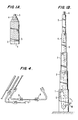
- Figs 1A and 1B are side elevational views of an antenna tower constructed in accordance with the invention in collapsed or retracted position and elevated position respectively;
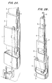
- Figs 2A and 2B are isometric views of successive sections of the tower, upon an enlarged scale, with preferred equilateral triangular tubular elements;
- Fig 3 is a transverse section near the bottom of the mast;
- Fig 4 is a fragmentary top elevation of the telescoped mast of Figs 2A and 2B, upon a larger scale.
- Referring to Figs 1A and 1B of the drawings, the mast or tower structure of the invention is shown constructed of a plurality of hollow equilateral triangular aluminium or similar thin-walled
tubular sections - At or near the corners or vertices of successively
adjacent tubes - A suitable cable harness arrangement is shown schematically in Fig. 1B, and portions in Figs. 2A and 2B.
- With the mast assembly fully retracted as shown in Fig. 1A, and with winch W, Fig. 1B, hand cranked by the operator, a tension is developed within the cable of the harness arrangement which tension, due to the low frictional resistance of the sheaves, is the same throughout the system. This cable tension is transmitted first from the winch drum affixed to the side of outermost section 1 upward to and around the sheave affixed near the upper edge of this outermost section. It then continues downward to and around the sheave affixed near the lower end of the next
inner section 2, then upward to and around a sheave affixed near the upper end ofsection 2. This connective means is continued through the successively inwardly located mast sections until the cable is finally terminated by means of a fixed connection to the lower end of the innermost (top) mast section. - As the tension in the cable is increased, all mast sections remain stationary until sufficient tension is developed to raise the lightest,
innermost mast section 5 in Fig. 1B. This section extends upward, out of the nextinnermost section 4, until it reaches the limit of its travel and becomes locked insection 4. As the cable tension is increased and becomes sufficient to raise the combined weights ofsections section 4 extending upward, out ofsection 3; and so on. - When the rotation of the winch is reversed, the
lower mast section 2, Fig. 1B, will retract into section 1 under the influence of gravity, and when fully seated,mast section 3 will retract intosection 2, etc., until all sections are nested as shown in FIG. 1A. However, when the winds are sufficienly strong, friction between the mast sections can prevent the smooth and orderly retraction just described. To avert the undesirable consequences resulting from such a situation, aretraction cable 6, Fig. 1B, is provided. This consists of a cable connected from the lower end of theuppermost section 5, extending directly downward to a sheave in the base of lowermost section 1, and thence to a drum on the winch W. - A satisfactory telescoping, mast or tower of this type has been constructed with the following section dimensions:

- For light weight construction, the sheet walls of the triangular tubular members may be apertured as by punched holes H, the inner punching of which adds structural reinforcement, or by other perforations or lattice structures.
- If desired, the inner tubular sections may initially be raised together before telescopically raising the successive inner tubes to successively higher elevation, and further modifications will also occur to those skilled in this art, and such being considered to fall within the spirit and scope of the invention as defined in the appended claims.
Claims (5)
- A telescoping antenna tower assembly comprising a plurality of hollow equilateral triangular aluminium tubular sections (1,2,3,4,5) bounding successively diminishing areas, one nested within the other(s) in parallel longitudinal coaxial relationship, sliding means (R) disposed between the succesive tubular sections (1,2,3,4,5) to permit sliding longitudinal axial relative movement, pulley means (P) mounted on the tubular sections, and winch means (W) disposed near the bottom of the outer tubular section (1) and connected with a cable link (C) longitudinally harnessed over the pulley means (P) to permit raising and lowering of the tubular sections (1,2,3,4,5) by the cable (C) in order to erect and lower the tower, characterised in that said sliding means is in the form of guide rollers (R) disposed at the corners of the sections (1,2,3,4,5), said cable link (C) being disposed within said sections (1,2,3,4,5) and that a retraction cable (6) is connected within the sections (1,2,3,4,5) between said winch means (W) and that inner tubular section (5) which forms the top of the tower for applying a pulling force to lower the tower.
- An assembly as claimed in claim 1 wherein said tubular sections are formed of similar thin planar aluminium sheets edge-mounted in similar extruded aluminium corner sections (5').
- An assembly as claimed in claim 2 wherein said sheets (S) are perforated for low weight and structural reinforcement.
- An assembly as claimed in claim 1 wherein said pulley means (P) comprises a pair of upper and lower pulleys mounted near a corner externally of said tubular section.
- An assembly as claimed in claim 1 wherein an antenna (A) is disposed within the innermost tube (5) to be raised and lowered therewith.
Applications Claiming Priority (2)
| Application Number | Priority Date | Filing Date | Title |
|---|---|---|---|
| US73323685A | 1985-05-10 | 1985-05-10 | |
| US733236 | 1985-05-10 |
Publications (3)
| Publication Number | Publication Date |
|---|---|
| EP0201645A2 EP0201645A2 (en) | 1986-11-20 |
| EP0201645A3 EP0201645A3 (en) | 1987-09-30 |
| EP0201645B1 true EP0201645B1 (en) | 1992-02-26 |
Family
ID=24946776
Family Applications (1)
| Application Number | Title | Priority Date | Filing Date |
|---|---|---|---|
| EP19850307842 Expired EP0201645B1 (en) | 1985-05-10 | 1985-10-30 | Telescoping lightweight antenna tower assembly and the like |
Country Status (4)
| Country | Link |
|---|---|
| EP (1) | EP0201645B1 (en) |
| CN (1) | CN1008034B (en) |
| CA (1) | CA1252197A (en) |
| DE (1) | DE3585444D1 (en) |
Cited By (1)
| Publication number | Priority date | Publication date | Assignee | Title |
|---|---|---|---|---|
| US20140311085A1 (en) * | 2011-12-09 | 2014-10-23 | Sea Wind Towers, S.L. | Assembly process of a telescopic tower |
Families Citing this family (15)
| Publication number | Priority date | Publication date | Assignee | Title |
|---|---|---|---|---|
| FR2633000A1 (en) * | 1988-06-16 | 1989-12-22 | Baumstummler Andre | Telescopic mast with manual or automatic drive |
| AT395627B (en) * | 1989-10-17 | 1993-02-25 | Waagner Biro Ag | Extensible system |
| AU644744B2 (en) * | 1991-08-15 | 1993-12-16 | Darex Engineering Pty. Ltd. | Extendible pole |
| FR2719070B1 (en) * | 1994-04-26 | 1997-01-10 | Pasquier Serrurerie Ferronneri | Telescopic mast. |
| US5995063A (en) * | 1998-08-13 | 1999-11-30 | Nortel Networks Corporation | Antenna structure |
| GB2406862B (en) * | 2003-10-09 | 2007-08-01 | Janile Ltd | Extendible mast |
| CN100422708C (en) * | 2004-12-14 | 2008-10-01 | 中国科学院安徽光学精密机械研究所 | Near-ground turbulence flow profiler and measuring method thereof |
| US8887450B2 (en) * | 2005-03-11 | 2014-11-18 | The Will-Burt Company | Support bearing assembly |
| CN100462250C (en) * | 2006-04-15 | 2009-02-18 | 富群 | Method for inducing wind from outside to inside |
| GB2460637B (en) * | 2008-05-31 | 2013-03-13 | Abacus Holdings Ltd | Extendable mast having an active extension and retraction |
| CN101950845B (en) * | 2010-10-15 | 2013-04-03 | 福建星海通信科技有限公司 | Telescopic antenna |
| ES2606786B1 (en) | 2015-09-23 | 2018-01-31 | Esteyco S.A.P. | GUIDE DEVICE FOR WINDOW TOWER ASSEMBLY |
| NL2017084B1 (en) * | 2016-07-01 | 2018-01-19 | Ijslander B V | SYSTEM FOR PLACING CONSTRUCTIONS ON A BACKGROUND |
| CN108729727A (en) * | 2017-04-24 | 2018-11-02 | 胡广生 | Composite material assembly type shaft tower |
| ES1269469Y (en) * | 2021-04-30 | 2021-09-23 | Equipson S A | LIFTING TOWER |
Family Cites Families (8)
| Publication number | Priority date | Publication date | Assignee | Title |
|---|---|---|---|---|
| US3328921A (en) * | 1964-06-02 | 1967-07-04 | Ralph W Keslin Inc | Self-supporting extension tower |
| SE311565B (en) * | 1966-08-05 | 1969-06-16 | Wikstrand & Berg Wibe Ab | |
| US3979873A (en) * | 1973-11-26 | 1976-09-14 | Mancole Company Limited | Extending boom construction |
| US3925949A (en) * | 1974-09-30 | 1975-12-16 | Tom T Mikulin | Structural member and method of making the same |
| FR2422792A1 (en) * | 1978-04-14 | 1979-11-09 | Icpp | Self-elevating radio mast - has telescopic lattice structure pivoting about trailer for extension by winch-operated cable hoist |
| FR2465050A2 (en) * | 1978-09-18 | 1981-03-20 | Vendramini D | TELESCOPIC MATERIAL |
| FR2446907A1 (en) * | 1979-01-18 | 1980-08-14 | Telecommunications Internal Ci | Telescopic pylon with locking elements - allows progressive collapse after failure of erecting winch wire using system of rollers and locking plates |
| FR2476727A2 (en) * | 1979-07-30 | 1981-08-28 | Icpp | Automatically raised mobile pylon on trailer - has battery operated hydraulic pump providing fluid pressure in jack to raise telescopic sections |
-
1985
- 1985-10-30 DE DE8585307842T patent/DE3585444D1/en not_active Expired - Fee Related
- 1985-10-30 EP EP19850307842 patent/EP0201645B1/en not_active Expired
-
1986
- 1986-01-09 CA CA000499302A patent/CA1252197A/en not_active Expired
- 1986-02-13 CN CN 86101025 patent/CN1008034B/en not_active Expired
Cited By (1)
| Publication number | Priority date | Publication date | Assignee | Title |
|---|---|---|---|---|
| US20140311085A1 (en) * | 2011-12-09 | 2014-10-23 | Sea Wind Towers, S.L. | Assembly process of a telescopic tower |
Also Published As
| Publication number | Publication date |
|---|---|
| CA1252197A (en) | 1989-04-04 |
| CN1008034B (en) | 1990-05-16 |
| EP0201645A2 (en) | 1986-11-20 |
| EP0201645A3 (en) | 1987-09-30 |
| CN86101025A (en) | 1986-11-05 |
| DE3585444D1 (en) | 1992-04-02 |
Similar Documents
| Publication | Publication Date | Title |
|---|---|---|
| US5101215A (en) | Telescoping lightweight antenna tower assembly and the like | |
| EP0201645B1 (en) | Telescoping lightweight antenna tower assembly and the like | |
| US4785309A (en) | Extendable antenna mast with independent retracting and lifting cables | |
| RU2042023C1 (en) | Telescopic supporting arrangement | |
| US5035094A (en) | Nested extension/retraction structure and method of fabrication | |
| US6046706A (en) | Antenna mast and method of using same | |
| US3385397A (en) | Extensible-retractile structure | |
| EP2746571A2 (en) | Wind turbine assembly system | |
| US7654923B2 (en) | Readily extendible telescopic lifting system | |
| EP3379079B1 (en) | Device for assembly and maintenance of a tower for a wind turbine and use of the same | |
| US6041558A (en) | Collapsible tower system for antenna or the like | |
| EP3812337A1 (en) | Tower system for performing work on an elongated structure | |
| US3977139A (en) | Tower having raising and lowering means | |
| US20170096830A1 (en) | Variable height telescoping lattice tower | |
| US4125193A (en) | Climbing device for climbing crane | |
| CN210620017U (en) | A scalable portal frame for towing formula construction elevator | |
| US2315873A (en) | Portable folding hoist | |
| US4326363A (en) | Waisted envelope for tubular building structures | |
| CN114069187B (en) | Self-expanding vertical log periodic antenna and method of use thereof | |
| KR20180044144A (en) | Portable lift | |
| WO2014052817A1 (en) | Hydraulic telescopic antenna mast system and method for operating the same | |
| CN104832076B (en) | A kind of Cordless curtain | |
| CN110011216B (en) | Crossing frame | |
| CN210843106U (en) | Lifting system of medical X-ray photography system detection device | |
| CA2032335A1 (en) | Telescoping lightweight antenna tower assembly and the like |
Legal Events
| Date | Code | Title | Description |
|---|---|---|---|
| PUAI | Public reference made under article 153(3) epc to a published international application that has entered the european phase |
Free format text: ORIGINAL CODE: 0009012 |
|
| AK | Designated contracting states |
Kind code of ref document: A2 Designated state(s): BE DE FR GB IT NL SE |
|
| PUAL | Search report despatched |
Free format text: ORIGINAL CODE: 0009013 |
|
| AK | Designated contracting states |
Kind code of ref document: A3 Designated state(s): BE DE FR GB IT NL SE |
|
| 17P | Request for examination filed |
Effective date: 19880323 |
|
| 17Q | First examination report despatched |
Effective date: 19890419 |
|
| GRAA | (expected) grant |
Free format text: ORIGINAL CODE: 0009210 |
|
| AK | Designated contracting states |
Kind code of ref document: B1 Designated state(s): BE DE FR GB IT NL SE |
|
| REF | Corresponds to: |
Ref document number: 3585444 Country of ref document: DE Date of ref document: 19920402 |
|
| ITF | It: translation for a ep patent filed |
Owner name: JACOBACCI & PERANI S.P.A. |
|
| ET | Fr: translation filed | ||
| PG25 | Lapsed in a contracting state [announced via postgrant information from national office to epo] |
Ref country code: GB Effective date: 19921030 |
|
| PG25 | Lapsed in a contracting state [announced via postgrant information from national office to epo] |
Ref country code: SE Effective date: 19921031 Ref country code: BE Effective date: 19921031 |
|
| PLBE | No opposition filed within time limit |
Free format text: ORIGINAL CODE: 0009261 |
|
| STAA | Information on the status of an ep patent application or granted ep patent |
Free format text: STATUS: NO OPPOSITION FILED WITHIN TIME LIMIT |
|
| 26N | No opposition filed | ||
| BERE | Be: lapsed |
Owner name: CHU ASSOCIATES INC. Effective date: 19921031 |
|
| PG25 | Lapsed in a contracting state [announced via postgrant information from national office to epo] |
Ref country code: NL Effective date: 19930501 |
|
| NLV4 | Nl: lapsed or anulled due to non-payment of the annual fee | ||
| GBPC | Gb: european patent ceased through non-payment of renewal fee |
Effective date: 19921030 |
|
| PG25 | Lapsed in a contracting state [announced via postgrant information from national office to epo] |
Ref country code: FR Effective date: 19930630 |
|
| PG25 | Lapsed in a contracting state [announced via postgrant information from national office to epo] |
Ref country code: DE Effective date: 19930701 |
|
| REG | Reference to a national code |
Ref country code: FR Ref legal event code: ST |
|
| EUG | Se: european patent has lapsed |
Ref document number: 85307842.6 Effective date: 19930510 |