EP3354874A1 - Exhaust assembly, exhaust system, and power pack for a vehicle - Google Patents
Exhaust assembly, exhaust system, and power pack for a vehicle Download PDFInfo
- Publication number
- EP3354874A1 EP3354874A1 EP18153187.2A EP18153187A EP3354874A1 EP 3354874 A1 EP3354874 A1 EP 3354874A1 EP 18153187 A EP18153187 A EP 18153187A EP 3354874 A1 EP3354874 A1 EP 3354874A1
- Authority
- EP
- European Patent Office
- Prior art keywords
- resonator
- turbocharger
- inlet
- exhaust
- outlet
- Prior art date
- Legal status (The legal status is an assumption and is not a legal conclusion. Google has not performed a legal analysis and makes no representation as to the accuracy of the status listed.)
- Granted
Links
Images




Classifications
-
- F—MECHANICAL ENGINEERING; LIGHTING; HEATING; WEAPONS; BLASTING
- F02—COMBUSTION ENGINES; HOT-GAS OR COMBUSTION-PRODUCT ENGINE PLANTS
- F02B—INTERNAL-COMBUSTION PISTON ENGINES; COMBUSTION ENGINES IN GENERAL
- F02B37/00—Engines characterised by provision of pumps driven at least for part of the time by exhaust
-
- B—PERFORMING OPERATIONS; TRANSPORTING
- B62—LAND VEHICLES FOR TRAVELLING OTHERWISE THAN ON RAILS
- B62M—RIDER PROPULSION OF WHEELED VEHICLES OR SLEDGES; POWERED PROPULSION OF SLEDGES OR SINGLE-TRACK CYCLES; TRANSMISSIONS SPECIALLY ADAPTED FOR SUCH VEHICLES
- B62M27/00—Propulsion devices for sledges or the like
- B62M27/02—Propulsion devices for sledges or the like power driven
-
- F—MECHANICAL ENGINEERING; LIGHTING; HEATING; WEAPONS; BLASTING
- F01—MACHINES OR ENGINES IN GENERAL; ENGINE PLANTS IN GENERAL; STEAM ENGINES
- F01N—GAS-FLOW SILENCERS OR EXHAUST APPARATUS FOR MACHINES OR ENGINES IN GENERAL; GAS-FLOW SILENCERS OR EXHAUST APPARATUS FOR INTERNAL-COMBUSTION ENGINES
- F01N1/00—Silencing apparatus characterised by method of silencing
- F01N1/02—Silencing apparatus characterised by method of silencing by using resonance
-
- F—MECHANICAL ENGINEERING; LIGHTING; HEATING; WEAPONS; BLASTING
- F01—MACHINES OR ENGINES IN GENERAL; ENGINE PLANTS IN GENERAL; STEAM ENGINES
- F01N—GAS-FLOW SILENCERS OR EXHAUST APPARATUS FOR MACHINES OR ENGINES IN GENERAL; GAS-FLOW SILENCERS OR EXHAUST APPARATUS FOR INTERNAL-COMBUSTION ENGINES
- F01N13/00—Exhaust or silencing apparatus characterised by constructional features
- F01N13/08—Other arrangements or adaptations of exhaust conduits
- F01N13/10—Other arrangements or adaptations of exhaust conduits of exhaust manifolds
- F01N13/107—More than one exhaust manifold or exhaust collector
-
- F—MECHANICAL ENGINEERING; LIGHTING; HEATING; WEAPONS; BLASTING
- F02—COMBUSTION ENGINES; HOT-GAS OR COMBUSTION-PRODUCT ENGINE PLANTS
- F02B—INTERNAL-COMBUSTION PISTON ENGINES; COMBUSTION ENGINES IN GENERAL
- F02B37/00—Engines characterised by provision of pumps driven at least for part of the time by exhaust
- F02B37/02—Gas passages between engine outlet and pump drive, e.g. reservoirs
-
- F—MECHANICAL ENGINEERING; LIGHTING; HEATING; WEAPONS; BLASTING
- F02—COMBUSTION ENGINES; HOT-GAS OR COMBUSTION-PRODUCT ENGINE PLANTS
- F02M—SUPPLYING COMBUSTION ENGINES IN GENERAL WITH COMBUSTIBLE MIXTURES OR CONSTITUENTS THEREOF
- F02M26/00—Engine-pertinent apparatus for adding exhaust gases to combustion-air, main fuel or fuel-air mixture, e.g. by exhaust gas recirculation [EGR] systems
- F02M26/02—EGR systems specially adapted for supercharged engines
- F02M26/04—EGR systems specially adapted for supercharged engines with a single turbocharger
- F02M26/05—High pressure loops, i.e. wherein recirculated exhaust gas is taken out from the exhaust system upstream of the turbine and reintroduced into the intake system downstream of the compressor
-
- F—MECHANICAL ENGINEERING; LIGHTING; HEATING; WEAPONS; BLASTING
- F02—COMBUSTION ENGINES; HOT-GAS OR COMBUSTION-PRODUCT ENGINE PLANTS
- F02M—SUPPLYING COMBUSTION ENGINES IN GENERAL WITH COMBUSTIBLE MIXTURES OR CONSTITUENTS THEREOF
- F02M26/00—Engine-pertinent apparatus for adding exhaust gases to combustion-air, main fuel or fuel-air mixture, e.g. by exhaust gas recirculation [EGR] systems
- F02M26/13—Arrangement or layout of EGR passages, e.g. in relation to specific engine parts or for incorporation of accessories
- F02M26/22—Arrangement or layout of EGR passages, e.g. in relation to specific engine parts or for incorporation of accessories with coolers in the recirculation passage
- F02M26/23—Layout, e.g. schematics
- F02M26/24—Layout, e.g. schematics with two or more coolers
-
- F—MECHANICAL ENGINEERING; LIGHTING; HEATING; WEAPONS; BLASTING
- F02—COMBUSTION ENGINES; HOT-GAS OR COMBUSTION-PRODUCT ENGINE PLANTS
- F02M—SUPPLYING COMBUSTION ENGINES IN GENERAL WITH COMBUSTIBLE MIXTURES OR CONSTITUENTS THEREOF
- F02M26/00—Engine-pertinent apparatus for adding exhaust gases to combustion-air, main fuel or fuel-air mixture, e.g. by exhaust gas recirculation [EGR] systems
- F02M26/13—Arrangement or layout of EGR passages, e.g. in relation to specific engine parts or for incorporation of accessories
- F02M26/41—Arrangement or layout of EGR passages, e.g. in relation to specific engine parts or for incorporation of accessories characterised by the arrangement of the recirculation passage in relation to the engine, e.g. to cylinder heads, liners, spark plugs or manifolds; characterised by the arrangement of the recirculation passage in relation to specially adapted combustion chambers
-
- B—PERFORMING OPERATIONS; TRANSPORTING
- B62—LAND VEHICLES FOR TRAVELLING OTHERWISE THAN ON RAILS
- B62M—RIDER PROPULSION OF WHEELED VEHICLES OR SLEDGES; POWERED PROPULSION OF SLEDGES OR SINGLE-TRACK CYCLES; TRANSMISSIONS SPECIALLY ADAPTED FOR SUCH VEHICLES
- B62M27/00—Propulsion devices for sledges or the like
- B62M27/02—Propulsion devices for sledges or the like power driven
- B62M2027/023—Snow mobiles characterised by engine mounting arrangements
-
- F—MECHANICAL ENGINEERING; LIGHTING; HEATING; WEAPONS; BLASTING
- F01—MACHINES OR ENGINES IN GENERAL; ENGINE PLANTS IN GENERAL; STEAM ENGINES
- F01N—GAS-FLOW SILENCERS OR EXHAUST APPARATUS FOR MACHINES OR ENGINES IN GENERAL; GAS-FLOW SILENCERS OR EXHAUST APPARATUS FOR INTERNAL-COMBUSTION ENGINES
- F01N2260/00—Exhaust treating devices having provisions not otherwise provided for
- F01N2260/06—Exhaust treating devices having provisions not otherwise provided for for improving exhaust evacuation or circulation, or reducing back-pressure
-
- F—MECHANICAL ENGINEERING; LIGHTING; HEATING; WEAPONS; BLASTING
- F01—MACHINES OR ENGINES IN GENERAL; ENGINE PLANTS IN GENERAL; STEAM ENGINES
- F01N—GAS-FLOW SILENCERS OR EXHAUST APPARATUS FOR MACHINES OR ENGINES IN GENERAL; GAS-FLOW SILENCERS OR EXHAUST APPARATUS FOR INTERNAL-COMBUSTION ENGINES
- F01N2590/00—Exhaust or silencing apparatus adapted to particular use, e.g. for military applications, airplanes, submarines
-
- F—MECHANICAL ENGINEERING; LIGHTING; HEATING; WEAPONS; BLASTING
- F02—COMBUSTION ENGINES; HOT-GAS OR COMBUSTION-PRODUCT ENGINE PLANTS
- F02B—INTERNAL-COMBUSTION PISTON ENGINES; COMBUSTION ENGINES IN GENERAL
- F02B75/00—Other engines
- F02B75/02—Engines characterised by their cycles, e.g. six-stroke
- F02B2075/022—Engines characterised by their cycles, e.g. six-stroke having less than six strokes per cycle
- F02B2075/025—Engines characterised by their cycles, e.g. six-stroke having less than six strokes per cycle two
-
- Y—GENERAL TAGGING OF NEW TECHNOLOGICAL DEVELOPMENTS; GENERAL TAGGING OF CROSS-SECTIONAL TECHNOLOGIES SPANNING OVER SEVERAL SECTIONS OF THE IPC; TECHNICAL SUBJECTS COVERED BY FORMER USPC CROSS-REFERENCE ART COLLECTIONS [XRACs] AND DIGESTS
- Y02—TECHNOLOGIES OR APPLICATIONS FOR MITIGATION OR ADAPTATION AGAINST CLIMATE CHANGE
- Y02T—CLIMATE CHANGE MITIGATION TECHNOLOGIES RELATED TO TRANSPORTATION
- Y02T10/00—Road transport of goods or passengers
- Y02T10/10—Internal combustion engine [ICE] based vehicles
- Y02T10/12—Improving ICE efficiencies
Definitions
- the present technology relates to a two-stroke engine based power pack for a vehicle, as well as an exhaust system and an exhaust assembly for use with a two-stroke engine.
- Vehicles such as snowmobiles often use power packs with two-stroke internal combustion engines and associated exhaust systems. While generally lighter and more powerful than a similar four-stroke engine, two-stroke engines may present some drawbacks.
- turbocharger Another potential tool for improving engine efficiency is the addition of a turbocharger, which uses energy from exhaust gases exiting the engine to provide higher pressure air input into combustion chambers of the engine, allowing for combustion of more fuel each cycle. This can be problematic for two-stroke engines, however, as the turbocharger does not recapture the fresh air and fuel leaking out the exhaust ports each cycle. Further, the additional air and fuel entering the combustion chambers may mean more air and fuel leaking out of the engine before combustion can occur.
- Tuned expansion chambers also known as tuning pipes, are often used for combating the air and fuel leakage problem of two-stroke engines.
- the tuned expansion chamber is connected between the engine exhaust ports and the muffler. As exhaust gases move through the chamber, a portion is reflected back to create a pressure wave pushing back against the exhaust ports. This pressure wave pushes fresh air and fuel back toward the combustion chambers, thereby at least partially resolving the air and fuel leakage problem.
- both the tuned expansion chamber and the turbocharger In order to both increase efficiency and combat the air and fuel leakage problem of two-stroke engines, one may contemplate implementing both the tuned expansion chamber and the turbocharger.
- both solutions utilize exhaust gases from the engine to work.
- the expansion chamber and the turbocharger could potentially be installed in series, the expansion chamber connected to the exhaust ports and the turbocharger connected to the expansion chamber. This is not optimal, however, as a portion of the exhaust gases would be reflected back toward the engine in the pressure wave created by the expansion chamber, reducing the energy from the exhaust gases available to the turbocharger. Further, the portion of the exhaust gases passing through the expansion chamber will cool and become less energetic in the distance between the exhaust ports and the turbocharger, once again reducing the capacity of the turbocharger to improve engine efficiency.
- turbocharger is connected between the engine and the expansion chamber will prevent any benefit to be gleaned from the expansion chamber, as the exhaust gases would be routed through a turbine and prevent a pressure wave from propagating back toward the engine).
- an exhaust assembly comprising a resonator including an inlet adapted for fluidly connecting to an exhaust manifold, and a closed end at an end of the resonator opposite the inlet; and a turbocharger passage extending from the resonator between the exhaust manifold and the closed end, the turbocharger passage defining an outlet.
- the turbocharger passage is disposed nearer to the inlet than to the closed end.
- the turbocharger passage is disposed at less than a third of a length of the resonator from the inlet, the length of the resonator being measured along a center line of the resonator from the inlet to the closed end.
- an outlet axis through a center of the outlet and normal to the outlet is disposed at an angle to an inlet axis through a center of the inlet and normal to the inlet.
- the angle between the outlet axis and the inlet axis, as measured from a center of the outlet to a center of the inlet, is greater than 90 degrees.
- the inlet and the outlet face at least partially in opposite directions.
- the resonator is bent in a U-shape such that a central portion of the resonator is farther from the inlet than the closed end is from the inlet.
- a central portion of the resonator has a larger diameter than either of the closed end and the inlet.
- a diameter of the resonator increases as the resonator extends from the inlet toward a central portion of the resonator; and the diameter of the resonator decreases as the resonator extends from the central portion toward the closed end.
- the exhaust assembly further comprises a flange about the outlet adapted for receiving a turbocharger disposed on the turbocharger passage.
- an exhaust system comprising an exhaust manifold adapted for connecting to an engine; an exhaust assembly operatively connected to the exhaust manifold, the exhaust assembly including a resonator including an inlet connected to the exhaust manifold, and a closed end at an end of the resonator opposite the inlet; and a turbocharger passage extending from the resonator between the exhaust manifold and the closed end, the turbocharger passage defining an outlet; a turbocharger operatively connected to the turbocharger passage and fluidly connected to the outlet; and a muffler fluidly connected to the turbocharger.
- the turbocharger passage is disposed nearer to the inlet than to the closed end.
- the turbocharger passage is disposed at less than a third of a length of the resonator from the inlet, the length of the resonator being measured along a center line of the resonator from the inlet to the closed end.
- the resonator is bent in a U-shape such that a central portion of the resonator is farther from the inlet than the closed end is from the inlet.
- a central portion of the resonator has a larger diameter than either of the closed end and the inlet.
- an outlet axis through a center of the outlet and normal to the outlet is disposed at an angle to an inlet axis through a center of the inlet and normal to the inlet.
- the inlet and the outlet face at least partially in opposite directions.
- a power pack comprising an engine; and an exhaust system operatively connected to the engine, the exhaust system comprising an exhaust manifold connected to the engine; an exhaust assembly operatively connected to the exhaust manifold, the exhaust assembly including a resonator including an inlet connected to the exhaust manifold, and a closed end at an end of the resonator opposite the inlet; and a turbocharger passage extending from the resonator between the exhaust manifold and the closed end, the turbocharger passage defining an outlet; a turbocharger operatively connected to the turbocharger passage and fluidly connected to the outlet; and a muffler fluidly connected to the turbocharger.
- a vehicle comprising a frame; at least one ground engaging member operatively connected to the frame; the power pack as described above, the engine being connected to the frame and being operatively connected to the at least one ground engaging member; and at least one seat connected to the frame.
- the resonator extends forward, to one of leftward and rightward, and then rearward from the manifold; the turbocharger passage extends upward and forward from a rear portion of the resonator; at least a portion of the turbocharger extends one of rightward and leftward of the turbocharger passage; and the muffler is disposed at an other one of rightward and leftward of the turbocharger passage.
- Implementations of the present technology each have at least one of the above-mentioned object and/or aspects, but do not necessarily have all of them. It should be understood that some aspects of the present technology that have resulted from attempting to attain the above-mentioned object may not satisfy this object and/or may satisfy other objects not specifically recited herein.
- a snowmobile 10 includes a forward end 12 and a rearward end 14 that are defined consistently with a forward travel direction of the snowmobile 10.
- the snowmobile 10 includes a frame 16 that includes a tunnel 18 and a front suspension assembly portion 22.
- a power pack 100 is disposed in a forward portion of the snowmobile 10.
- the power pack 100 includes an engine 110, which in the present implementation is a two-stroke internal combustion engine 110, connected to the frame 16.
- Two skis 26 are positioned at the forward end 12 of the snowmobile 10 and are attached to the front suspension assembly portion 22 of the frame 16 through front suspension assemblies 28.
- Each front suspension assembly 28 includes a shock absorber assembly 29, a ski leg 30 and supporting arms 32.
- Ball joints and steering rods 77 operatively connect the skis 26 to a steering column 34.
- a steering device in the form of handlebar 36 is attached to the upper end of the steering column 34 to allow a driver to rotate the ski legs 30 and thus the skis 26, in order to steer the snowmobile 10.
- a ground engaging member 38 in the form of an endless drive track 38 is disposed generally under the tunnel 18 and is operatively connected to the engine 110 through a continuously variable transmission (CVT) system (not shown).
- the endless drive track 38 is driven to run about a rear suspension assembly 42 for propulsion of the snowmobile 10.
- the endless drive track 38 has a plurality of lugs 55 extending from an outer surface thereof to provide traction to the track 38.
- the rear suspension assembly 42 includes a pair of drive sprockets 70 (shown schematically) mounted on a drive axle 72 (shown schematically) for driving the endless drive track 38.
- the rear suspension assembly 42 includes a pair of slide rails 44 in sliding contact with the endless drive track 38.
- the rear suspension assembly 42 also includes a plurality of shock absorbers 46 which may further include coil springs 47 surrounding the shock absorbers 46.
- Suspension arms 48 and 50 are provided to attach the slide rails 44 to the frame 16.
- a plurality of idler wheels 52 are also provided in the rear suspension assembly 42. Other types and geometries of rear suspension assemblies are also contemplated.
- fairings 54 enclose the power pack 100 and the CVT, thereby providing an external shell that protects the power pack 100 and the CVT.
- the fairings 54 include a hood and one or more side panels that can be opened to allow access to the power pack 100 and the CVT when this is required, for example, for inspection or maintenance of the engine 110 and/or the CVT.
- a windshield 56 is connected to the fairings 54 near the forward end 12 of the snowmobile 10. Alternatively the windshield 56 could be connected directly to the handlebar 36. The windshield 56 acts as a wind screen to lessen the force of the air on the driver while the snowmobile 10 is moving forward.
- a straddle-type seat 58 is positioned over the tunnel 18, atop a fuel tank (not shown).
- the seat 58 is adapted to accommodate a driver of the snowmobile 10 but it is contemplated that the seat 58 could also be configured to accommodate a passenger as well.
- a fuel tank fill opening covered by a cap 51 is disposed on the upper surface of the fuel tank in front of the seat 58.
- Two footrests 40 are positioned on opposite sides of the snowmobile 10 below the seat 58 to accommodate the driver's feet.
- the tunnel 18 consists of one or more pieces of sheet metal arranged to form an inverted U-shape that is connected at the front to the engine cradle portion 20 and extends rearward therefrom.
- a snow flap 19 is disposed at the rear end 14 of the snowmobile 10. The snow flap 19 protects against dirt that can be projected upward from the drive track 38 when the snowmobile 10 is being driven. It is contemplated that the snow flap 19 could be omitted.
- the snowmobile 10 has other features and components which would be readily recognized by one of ordinary skill in the art. Further explanation and description of these components will not be provided herein.
- the power pack 100 for the snowmobile 10 includes the two-stroke engine 110 which provides power to the snowmobile 10, an exhaust manifold 180, an exhaust assembly 200, a turbocharger 160 and a muffler 190. Together, the exhaust manifold 180, the exhaust assembly 200, the turbocharger 160 and the muffler 190 make up part of an exhaust system 150 for connecting to the two-stroke engine 110.
- the engine 110 has a crankcase 112 housing a portion of a crankshaft 114.
- the crankshaft 114 protrudes from the crankcase 112.
- the crankshaft 114 could drive an output shaft connected directly to the end of the crankshaft 114 or offset from the crankshaft 114 and driven by driving means such as gears in order to drive a drive pulley of the CVT.
- the crankshaft 114 could drive, using gears for example, a counterbalance shaft housed in part in the crankcase 112 and that the drive pulley could be connected to the counterbalance shaft, in which case, the crankshaft 114 would not have to protrude from the crankcase 112 for this purpose.
- a cylinder block 116 is disposed on top of and connected to the crankcase 112.
- the cylinder block 116 defines two cylinders (not shown), each containing a piston (not shown).
- a cylinder head 118 is disposed on top of and is connected to the cylinder block 116. Rotation of the crankshaft 114 causes the pistons to reciprocate inside their respective cylinders in the manner generally known in the art for a two-stroke engine. Further details relating to two-stroke engines can be found at least in International Publication WO 2016/193902 A2, published December 8, 2016 .
- Air is supplied to the crankcase 112 via a pair of air intake ports (not shown) formed in the back of the cylinder block 116. It is contemplated that the air intake ports could be formed in the crankcase 112. It is also contemplated that there could be more than one air intake port per cylinder.
- a pair of throttle bodies 122 is connected to the pair of air intake ports. Each throttle body 122 has a throttle plate 124 that can be rotated to control the air flow to the engine 110. Although not illustrated in the Figures, the throttle plates 124 could be controlled by one or more throttle cables connected to a throttle lever or a throttle motor could be used to change the position of the throttle plates 124. It is also contemplated that each throttle plate 124 could be actuated by its own throttle motor.
- Air is supplied to the throttle bodies 122 by a plenum 130 connected thereto, shown schematically in Figures 2 and 5 .
- Compressed intake air is delivered from the turbocharger 160 to the plenum 130 by a pipe 132 extending from an outlet 168 of the turbocharger 160.
- Exhaust gases enter into and pass through a turbine side 162 of the turbocharger 160 to drive a turbine 172 (see Figure 5 ).
- the turbine 172 in turn drives compression of intake air brought in through an air intake 166 on a compression side 164 of the turbocharger 160.
- the compressed intake air from the compression side 164 of the turbocharger 160 is then sent out through the pipe 132 to the plenum 130.
- the plenum 130 includes an intercooler 134 (shown schematically in Figures 2 and 5 ) to cool the compressed intake air. It is contemplated that the intercooler 134 could be included in the pipe 132. It is also contemplated that the intercooler 134 could be disposed between the pipe 132 and the plenum 130. It is further contemplated that some implementations may not include the intercooler 134.
- the turbocharger 160 thus delivers air at an increased pressure to the plenum 130 as mentioned above, increasing the air pressure entering the engine 110. This generally improves combustion efficiency of the two-stroke engine 110. Specifics related to delivery of the exhaust gases from the engine 110 to the turbocharger 160 are described in more detail below.
- each cylinder defines one main exhaust port and two auxiliary exhaust ports (not shown). It is contemplated that each cylinder could have only one, two or more than three exhaust ports.
- the exhaust ports connect, directly or indirectly, to an exhaust manifold 180.
- the exhaust manifold 180 is connected to the front of the cylinder block 104.
- the power pack 100 includes the exhaust assembly 200, illustrated in isolation in Figures 6 to 8 .
- the exhaust assembly 200 is connected to a front end of the exhaust manifold 180.
- the exhaust assembly 200 is a stainless steel hollow body disposed between the engine 110 and the turbocharger 160 for conducting exhaust gases therebetween. It is contemplated that the exhaust assembly 200 could be composed of different materials, including but not limited to: carbon fiber and any appropriate metal or alloy. It is also contemplated that the exhaust assembly 200 could be composed of several parts, of same or different materials, joined together by different methods including, but not limited to, welding and fastening. It is further contemplated that the exhaust assembly 200 could be several parts removably connected together, such that different components of the exhaust assembly 200 could be removed or replaced as need be. It is further contemplated that the exhaust assembly 200 could include further features depending on the implementation, including but not limited to: sensors, structural reinforcements, and fasteners for connecting the exhaust assembly 200 to adjoining elements.
- the exhaust assembly 200 includes an inlet 220 which receives exhaust gases from the exhaust manifold 180 when the engine 110 is operating.
- the inlet 220 includes a flange 222 in the exhaust assembly 200 to aid in sealingly connecting the exhaust assembly 200 to the exhaust manifold 180.
- the exhaust manifold 180 could include a flange for sealing around the exhaust assembly 200 in some implementations. It is also contemplated that the exhaust assembly 200 and the exhaust manifold 180 could be welded together.
- a resonator 210 Extending forward from the inlet 220 of the exhaust assembly 200 is a resonator 210.
- the resonator 210 is fluidly connected to the inlet 220 and terminates in a closed end 230.
- the resonator 210 extends forward away from the exhaust manifold 180, slightly rightward, wraps around leftward and then backward toward the manifold 180 and the engine 110.
- the resonator 210 forms a U-shape, allowing the exhaust assembly 200 to be accommodated in an engine compartment of the snowmobile 10.
- a central portion 212 of the resonator 210 is farther from the inlet 220 than the closed end 230 is from the inlet 220, as can be seen in the Figures.
- the resonator 210 could be formed in a mirror image of the form illustrated in the Figures, specifically extending forward, slightly leftward, wrapping around rightward and then backward toward the manifold 180 and the engine 110. It is also contemplated that the resonator 210 could be differently bent and shaped, depending on the implementation. It is further contemplated that the resonator 210 could be straight, depending on the implementation of the snowmobile 10.
- the central portion 212 of the resonator 210 is larger than the inlet 220 and the closed end 230. This can be seen through further inspection of diameters of the resonator 210, as measured normal to a center line 202 running through a center of the resonator 210. In Figure 8 , three example diameters are illustrated at three points along the center line 202: at the inlet 220, at the closed end 230, and in the central portion 212. As can be seen in the Figure 8 , the central portion 212 of the resonator 210 has a larger diameter 284 than either of a diameter 286 of the closed end 230 and a diameter 282 of the inlet 220.
- the diameter of the resonator 210 increases as the resonator 210 extends from the inlet 220 toward the central portion 212 of the resonator. The diameter then decreases as the resonator 210 extends from the central portion 212 toward the closed end 230.
- the diameter of the resonator 210 increases in small linear increments, but it is contemplated that the diameter could vary smoothly along all or a portion of the length of the resonator 210.
- the resonator 210 allows the resonator 210 to provide an effect similar to an expansion chamber, which is sometimes included between a two-stroke engine and its corresponding muffler.
- exhaust gases entering the resonator 210 will cause a pressure wave to reflect back cyclically to the exhaust manifold 180. This pressure wave helps prevent the escape of freshly injected fuel, instead keeping the fuel and air in the engine 110 to be combusted.
- the exhaust assembly 200 further includes a turbocharger passage 250, extending upward and forward from the resonator 210.
- the turbocharger passage 250 defines an outlet 254 through which exhaust gases received through the inlet 220 can exit the exhaust assembly 200.
- a flange 252 is disposed about the outlet 254 for receiving the turbocharger 160 on an end of the turbocharger passage 250.
- the turbocharger passage 250 is described in further detail below.
- the power pack 100 further includes the turbocharger 160 and the muffler 190.
- the turbocharger 160 is connected to the exhaust assembly 200 at the flange 252 of the turbocharger passage 250.
- the muffler 190 is fluidly connected to the turbocharger 160 by pipes 192 and 194. A portion of the turbocharger 160 extends leftward from the turbocharger passage 250, as is illustrated in Figure 2 .
- the pipes 192, 194 extend rightward from the turbocharger passage 250 and the turbocharger 160.
- the muffler 190 is thus disposed rightward of the turbocharger passage 250.
- turbocharger 160 and the muffler 190 could be disposed in a mirror-image configuration in some implementations, where portions of the turbocharger 160 extend rightward from the turbocharger passage 250 and the muffler 190 is disposed leftward of the turbocharger passage 250.
- the turbocharger 160 is fluidly connected to the outlet 254 such that exhaust gases leaving the outlet 254 enter the turbine side 162 of the turbocharger 160. While passing through the turbine side 162, at least a portion of the exhaust gases drive the turbine 172, as described above. The exhaust gases that drive the turbine 172 then exit a turbine side 170 of the turbocharger 160 and pass through the pipe 192 to the muffler 190. A portion of the exhaust gases entering the turbocharger 160 may be diverted instead to a waste gate 174, for example when there is an excess of exhaust gases above what is necessary to drive the turbine 172. The waste gate 174 delivers the excess exhaust gases through the pipe 194, which in turn connects to the pipe 192, as is illustrated in Figures 2 to 4 .
- the turbocharger passage 250 extends forward and upward away from the inlet 220 from a rear portion of the resonator 210.
- the inlet 220 and the outlet 254 face partly in opposite directions (rearward and forward, respectively).
- axes passing through the outlet 254 and the inlet 220 are depicted in Figures 6 and 7 .
- An outlet axis 258 passes through a center 256 of the outlet 254, normal to the outlet 254.
- An inlet axis 226 passes through a center 224 of the inlet 220, normal to the inlet 220.
- the outlet axis 258 is disposed at an angle 260 of about 135 degrees to the inlet axis 226, as measured from the center 224 to the center 256. It is contemplated that the angle 260 could be larger or smaller than 135 degrees. For exhaust gases to flow from the inlet 220 out through the outlet 252, the angle 260 would be greater than 90 degrees.
- the turbocharger passage 250 is disposed nearer to the inlet 220 than to the closed end 230. Specifically, the turbocharger passage 250 is disposed about a tenth of the length of the center line 202 of the resonator 210 away from the inlet 220, as measured from the inlet 220 toward the closed end 230. It is contemplated that the turbocharger passage 250 could be disposed at less than a third of the length of the center line 202 of the resonator 210 away from the inlet 220. It is also contemplated that the turbocharger passage 250 could be closer or farther from the inlet 220, depending on the implementation.
- the exhaust gases entering through the inlet 220 will generally be directed up through the turbocharger passage 250 by the pressure wave issuing from the resonator 210. This allows the exhaust gases to be directed to the turbocharger 160, rather than propagating through the resonator 210 (as it would for an expansion chamber). If the exhaust gases were directed into an expansion chamber with the turbocharger 160 connected in series thereto, the exhaust gases would heat the expansion chamber.
- the arrangement of the turbocharger passage 250 near the inlet 220 prevents some of the heating of the resonator 210 and allows the resonator 210 to operate at a cooler temperature than the expansions chamber and turbocharger arrangement described above.
- Expansion chambers and resonators must be designed with their operating temperatures taken into consideration in order to provide the right frequency pressure wave to combat air and fuel leakage. Since the wave frequency is directly tied to the speed of sound in air, and the speed of sound in air is temperature dependent, hotter chambers/resonators will generally need to be larger than similar chambers/resonators operating at a lower temperature. By reducing operating temperature for the resonator 210, the overall length as measured along the center line 202 will be reduced compared to the similar expansion chamber described above. Depending on specifics of any given implementation, this can improve the weight and size characteristics of the exhaust assembly 200 compared to a similar expansion chamber and turbocharger series arrangement.
- turbocharger passage 250 nearer to the inlet 220 than to the closed end 230 can help further increase efficiency of the two-stroke engine 110.
- exhaust gases will pass through the inlet 220 and out the outlet 252 to the turbocharger 160 at a higher temperature than if the turbocharger passage 250 were disposed farther from the inlet 220 or if the turbocharger 160 were connected in series at the end of an expansion chamber.
- the turbocharger passage 250, and thus the turbocharger 160, near to the inlet 220 the exhaust gases have less time and distance over which to cool. Higher temperature exhaust gases entering the turbocharger 160 generally lead to higher efficiency of the turbocharger 160.
- the efficiency of the engine 110 can thus be improved by the arrangement of the resonator 210 and the turbocharger 160 brought together by the exhaust assembly 200 over arrangements placing the turbocharger 160 at greater distances from the exhaust manifold 180 or arrangements not including a resonator 210.
Landscapes
- Engineering & Computer Science (AREA)
- Chemical & Material Sciences (AREA)
- Combustion & Propulsion (AREA)
- Mechanical Engineering (AREA)
- General Engineering & Computer Science (AREA)
- Transportation (AREA)
- Exhaust Silencers (AREA)
- Supercharger (AREA)
Abstract
Description
- The present technology relates to a two-stroke engine based power pack for a vehicle, as well as an exhaust system and an exhaust assembly for use with a two-stroke engine.
- Vehicles such as snowmobiles often use power packs with two-stroke internal combustion engines and associated exhaust systems. While generally lighter and more powerful than a similar four-stroke engine, two-stroke engines may present some drawbacks.
- Some common drawbacks are due to the cycle of two-stroke engines, where each time new air and fuel are loaded into the combustion chambers of a two-stroke engine, a portion of the air and fuel may leak out of the engine through the exhaust port(s) before combustion can occur. This contributes to pollution created by the vehicle, as well as reducing the overall fuel efficiency.
- Although the above drawbacks may be resolved by switching to a four-stroke engine, doing so would result in losing the advantages typically associated with two-stroke engine, namely a simplified construction, more power (two-stroke engines have a combustion in each combustion chamber at every revolution, four-stoke engines at every two revolutions), and a lighter weight. These advantages of two-stroke engines are important features for vehicles such as motorcycles, snowmobiles and other recreational vehicles.
- Another potential tool for improving engine efficiency is the addition of a turbocharger, which uses energy from exhaust gases exiting the engine to provide higher pressure air input into combustion chambers of the engine, allowing for combustion of more fuel each cycle. This can be problematic for two-stroke engines, however, as the turbocharger does not recapture the fresh air and fuel leaking out the exhaust ports each cycle. Further, the additional air and fuel entering the combustion chambers may mean more air and fuel leaking out of the engine before combustion can occur.
- Tuned expansion chambers, also known as tuning pipes, are often used for combating the air and fuel leakage problem of two-stroke engines. The tuned expansion chamber is connected between the engine exhaust ports and the muffler. As exhaust gases move through the chamber, a portion is reflected back to create a pressure wave pushing back against the exhaust ports. This pressure wave pushes fresh air and fuel back toward the combustion chambers, thereby at least partially resolving the air and fuel leakage problem.
- In order to both increase efficiency and combat the air and fuel leakage problem of two-stroke engines, one may contemplate implementing both the tuned expansion chamber and the turbocharger. Unfortunately, both solutions utilize exhaust gases from the engine to work. The expansion chamber and the turbocharger could potentially be installed in series, the expansion chamber connected to the exhaust ports and the turbocharger connected to the expansion chamber. This is not optimal, however, as a portion of the exhaust gases would be reflected back toward the engine in the pressure wave created by the expansion chamber, reducing the energy from the exhaust gases available to the turbocharger. Further, the portion of the exhaust gases passing through the expansion chamber will cool and become less energetic in the distance between the exhaust ports and the turbocharger, once again reducing the capacity of the turbocharger to improve engine efficiency. It should also be noted that the opposite configuration, where the turbocharger is connected between the engine and the expansion chamber will prevent any benefit to be gleaned from the expansion chamber, as the exhaust gases would be routed through a turbine and prevent a pressure wave from propagating back toward the engine).
- There is therefore a desire for a power pack including a two-stroke engine and an associated exhaust system which addresses the above described drawbacks.
- It is an object of the present technology to ameliorate at least some of the inconveniences present in the prior art.
- According to one broad aspect of the present technology, there is provided an exhaust assembly, comprising a resonator including an inlet adapted for fluidly connecting to an exhaust manifold, and a closed end at an end of the resonator opposite the inlet; and a turbocharger passage extending from the resonator between the exhaust manifold and the closed end, the turbocharger passage defining an outlet.
- In some implementations, the turbocharger passage is disposed nearer to the inlet than to the closed end.
- In some implementations, the turbocharger passage is disposed at less than a third of a length of the resonator from the inlet, the length of the resonator being measured along a center line of the resonator from the inlet to the closed end.
- In some implementations, an outlet axis through a center of the outlet and normal to the outlet is disposed at an angle to an inlet axis through a center of the inlet and normal to the inlet.
- In some implementations, the angle between the outlet axis and the inlet axis, as measured from a center of the outlet to a center of the inlet, is greater than 90 degrees.
- In some implementations, the inlet and the outlet face at least partially in opposite directions.
- In some implementations, the resonator is bent in a U-shape such that a central portion of the resonator is farther from the inlet than the closed end is from the inlet.
- In some implementations, a central portion of the resonator has a larger diameter than either of the closed end and the inlet.
- In some implementations, a diameter of the resonator increases as the resonator extends from the inlet toward a central portion of the resonator; and the diameter of the resonator decreases as the resonator extends from the central portion toward the closed end.
- In some implementations, the exhaust assembly further comprises a flange about the outlet adapted for receiving a turbocharger disposed on the turbocharger passage.
- According to another broad aspect of the present technology, there is provided an exhaust system, comprising an exhaust manifold adapted for connecting to an engine; an exhaust assembly operatively connected to the exhaust manifold, the exhaust assembly including a resonator including an inlet connected to the exhaust manifold, and a closed end at an end of the resonator opposite the inlet; and a turbocharger passage extending from the resonator between the exhaust manifold and the closed end, the turbocharger passage defining an outlet; a turbocharger operatively connected to the turbocharger passage and fluidly connected to the outlet; and a muffler fluidly connected to the turbocharger.
- In some implementations, the turbocharger passage is disposed nearer to the inlet than to the closed end.
- In some implementations, the turbocharger passage is disposed at less than a third of a length of the resonator from the inlet, the length of the resonator being measured along a center line of the resonator from the inlet to the closed end.
- In some implementations, the resonator is bent in a U-shape such that a central portion of the resonator is farther from the inlet than the closed end is from the inlet.
- In some implementations, a central portion of the resonator has a larger diameter than either of the closed end and the inlet.
- In some implementations, an outlet axis through a center of the outlet and normal to the outlet is disposed at an angle to an inlet axis through a center of the inlet and normal to the inlet.
- In some implementations, the inlet and the outlet face at least partially in opposite directions.
- According to yet another broad aspect of the present technology, there is provided a power pack comprising an engine; and an exhaust system operatively connected to the engine, the exhaust system comprising an exhaust manifold connected to the engine; an exhaust assembly operatively connected to the exhaust manifold, the exhaust assembly including a resonator including an inlet connected to the exhaust manifold, and a closed end at an end of the resonator opposite the inlet; and a turbocharger passage extending from the resonator between the exhaust manifold and the closed end, the turbocharger passage defining an outlet; a turbocharger operatively connected to the turbocharger passage and fluidly connected to the outlet; and a muffler fluidly connected to the turbocharger.
- According to yet another broad aspect of the present technology, there is provided a vehicle comprising a frame; at least one ground engaging member operatively connected to the frame; the power pack as described above, the engine being connected to the frame and being operatively connected to the at least one ground engaging member; and at least one seat connected to the frame.
- In some implementations, the resonator extends forward, to one of leftward and rightward, and then rearward from the manifold; the turbocharger passage extends upward and forward from a rear portion of the resonator; at least a portion of the turbocharger extends one of rightward and leftward of the turbocharger passage; and the muffler is disposed at an other one of rightward and leftward of the turbocharger passage.
- For purposes of this application, terms related to spatial orientation such as forwardly, rearward, upwardly, downwardly, left, and right, are as they would normally be understood by an operator of the vehicle riding thereon in a normal driving position. Terms related to spatial orientation when describing or referring to components or sub-assemblies of the vehicle, separately from the vehicle, should be understood as they would be understood when these components or sub-assemblies are mounted to the vehicle, unless specified otherwise in this application.
- Implementations of the present technology each have at least one of the above-mentioned object and/or aspects, but do not necessarily have all of them. It should be understood that some aspects of the present technology that have resulted from attempting to attain the above-mentioned object may not satisfy this object and/or may satisfy other objects not specifically recited herein.
- Additional and/or alternative objects, features, and advantages of the implementations of the present invention will become apparent from the following description, the accompanying drawings, and the appended claims.
- For a better understanding of the present invention as well as other objects and further features thereof, reference is made to the following description which is to be used in conjunction with the accompanying drawings, where:
-
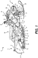
Figure 1 is a right side elevation view of a snowmobile; -
Figure 2 is a top plan view of a power pack of the snowmobile ofFigure 1 ; -
Figure 3 is a rear, left side perspective view of the power pack ofFigure 2 ; -
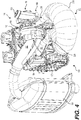
Figure 4 is a front, right side perspective view of the power pack ofFigure 2 ; -
Figure 5 is a right side elevation view of the power pack ofFigure 2 , with a muffler and its connecting pipes removed; -
Figure 6 is a top, rear, left side perspective view of an exhaust assembly of the power pack ofFigure 2 ; -
Figure 7 is a rear, right side perspective view of the exhaust assembly ofFigure 6 ; and -
Figure 8 is a top, rear side perspective view of the exhaust assembly ofFigure 6 . - Although the present technology is described below with respect to a snowmobile, it is contemplated that aspects thereof could be applied to other vehicles having two-stroke engines, including, but not limited to: side-by-side vehicles (SSVs), all-terrain vehicles (ATVs), and on-road vehicles such as motorcycles.
- Turning now to
Figure 1 , asnowmobile 10 includes aforward end 12 and arearward end 14 that are defined consistently with a forward travel direction of thesnowmobile 10. Thesnowmobile 10 includes aframe 16 that includes atunnel 18 and a frontsuspension assembly portion 22. Apower pack 100 is disposed in a forward portion of thesnowmobile 10. Thepower pack 100 includes anengine 110, which in the present implementation is a two-strokeinternal combustion engine 110, connected to theframe 16. Twoskis 26 are positioned at theforward end 12 of thesnowmobile 10 and are attached to the frontsuspension assembly portion 22 of theframe 16 throughfront suspension assemblies 28. Eachfront suspension assembly 28 includes ashock absorber assembly 29, aski leg 30 and supportingarms 32. Ball joints and steeringrods 77 operatively connect theskis 26 to asteering column 34. A steering device in the form ofhandlebar 36 is attached to the upper end of thesteering column 34 to allow a driver to rotate theski legs 30 and thus theskis 26, in order to steer thesnowmobile 10. - A
ground engaging member 38 in the form of anendless drive track 38 is disposed generally under thetunnel 18 and is operatively connected to theengine 110 through a continuously variable transmission (CVT) system (not shown). Theendless drive track 38 is driven to run about arear suspension assembly 42 for propulsion of thesnowmobile 10. Theendless drive track 38 has a plurality oflugs 55 extending from an outer surface thereof to provide traction to thetrack 38. - The
rear suspension assembly 42 includes a pair of drive sprockets 70 (shown schematically) mounted on a drive axle 72 (shown schematically) for driving theendless drive track 38. Therear suspension assembly 42 includes a pair of slide rails 44 in sliding contact with theendless drive track 38. Therear suspension assembly 42 also includes a plurality ofshock absorbers 46 which may further includecoil springs 47 surrounding theshock absorbers 46.Suspension arms frame 16. A plurality ofidler wheels 52 are also provided in therear suspension assembly 42. Other types and geometries of rear suspension assemblies are also contemplated. - At the
forward end 12 of thesnowmobile 10,fairings 54 enclose thepower pack 100 and the CVT, thereby providing an external shell that protects thepower pack 100 and the CVT. Thefairings 54 include a hood and one or more side panels that can be opened to allow access to thepower pack 100 and the CVT when this is required, for example, for inspection or maintenance of theengine 110 and/or the CVT. Awindshield 56 is connected to thefairings 54 near theforward end 12 of thesnowmobile 10. Alternatively thewindshield 56 could be connected directly to thehandlebar 36. Thewindshield 56 acts as a wind screen to lessen the force of the air on the driver while thesnowmobile 10 is moving forward. - A straddle-
type seat 58 is positioned over thetunnel 18, atop a fuel tank (not shown). Theseat 58 is adapted to accommodate a driver of thesnowmobile 10 but it is contemplated that theseat 58 could also be configured to accommodate a passenger as well. A fuel tank fill opening covered by acap 51 is disposed on the upper surface of the fuel tank in front of theseat 58. Twofootrests 40 are positioned on opposite sides of thesnowmobile 10 below theseat 58 to accommodate the driver's feet. - The
tunnel 18 consists of one or more pieces of sheet metal arranged to form an inverted U-shape that is connected at the front to the engine cradle portion 20 and extends rearward therefrom. Asnow flap 19 is disposed at therear end 14 of thesnowmobile 10. Thesnow flap 19 protects against dirt that can be projected upward from thedrive track 38 when thesnowmobile 10 is being driven. It is contemplated that thesnow flap 19 could be omitted. - The
snowmobile 10 has other features and components which would be readily recognized by one of ordinary skill in the art. Further explanation and description of these components will not be provided herein. - The
power pack 100 for thesnowmobile 10 according to the present technology will now be described with reference toFigures 2 to 5 . Thepower pack 100 includes the two-stroke engine 110 which provides power to thesnowmobile 10, anexhaust manifold 180, anexhaust assembly 200, aturbocharger 160 and amuffler 190. Together, theexhaust manifold 180, theexhaust assembly 200, theturbocharger 160 and themuffler 190 make up part of anexhaust system 150 for connecting to the two-stroke engine 110. - The
engine 110 has acrankcase 112 housing a portion of acrankshaft 114. As can be seen inFigure 3 , thecrankshaft 114 protrudes from thecrankcase 112. It is contemplated that thecrankshaft 114 could drive an output shaft connected directly to the end of thecrankshaft 114 or offset from thecrankshaft 114 and driven by driving means such as gears in order to drive a drive pulley of the CVT. It is also contemplated that thecrankshaft 114 could drive, using gears for example, a counterbalance shaft housed in part in thecrankcase 112 and that the drive pulley could be connected to the counterbalance shaft, in which case, thecrankshaft 114 would not have to protrude from thecrankcase 112 for this purpose. - A
cylinder block 116 is disposed on top of and connected to thecrankcase 112. Thecylinder block 116 defines two cylinders (not shown), each containing a piston (not shown). Acylinder head 118 is disposed on top of and is connected to thecylinder block 116. Rotation of thecrankshaft 114 causes the pistons to reciprocate inside their respective cylinders in the manner generally known in the art for a two-stroke engine. Further details relating to two-stroke engines can be found at least in International PublicationWO 2016/193902 A2, published December 8, 2016 . - Air is supplied to the
crankcase 112 via a pair of air intake ports (not shown) formed in the back of thecylinder block 116. It is contemplated that the air intake ports could be formed in thecrankcase 112. It is also contemplated that there could be more than one air intake port per cylinder. A pair ofthrottle bodies 122 is connected to the pair of air intake ports. Eachthrottle body 122 has athrottle plate 124 that can be rotated to control the air flow to theengine 110. Although not illustrated in the Figures, thethrottle plates 124 could be controlled by one or more throttle cables connected to a throttle lever or a throttle motor could be used to change the position of thethrottle plates 124. It is also contemplated that eachthrottle plate 124 could be actuated by its own throttle motor. - Air is supplied to the
throttle bodies 122 by aplenum 130 connected thereto, shown schematically inFigures 2 and5 . Compressed intake air is delivered from theturbocharger 160 to theplenum 130 by apipe 132 extending from anoutlet 168 of theturbocharger 160. Exhaust gases enter into and pass through aturbine side 162 of theturbocharger 160 to drive a turbine 172 (seeFigure 5 ). Theturbine 172 in turn drives compression of intake air brought in through anair intake 166 on acompression side 164 of theturbocharger 160. The compressed intake air from thecompression side 164 of theturbocharger 160 is then sent out through thepipe 132 to theplenum 130. Theplenum 130 includes an intercooler 134 (shown schematically inFigures 2 and5 ) to cool the compressed intake air. It is contemplated that the intercooler 134 could be included in thepipe 132. It is also contemplated that the intercooler 134 could be disposed between thepipe 132 and theplenum 130. It is further contemplated that some implementations may not include the intercooler 134. - The
turbocharger 160 thus delivers air at an increased pressure to theplenum 130 as mentioned above, increasing the air pressure entering theengine 110. This generally improves combustion efficiency of the two-stroke engine 110. Specifics related to delivery of the exhaust gases from theengine 110 to theturbocharger 160 are described in more detail below. - As the pistons reciprocate, air from the
crankcase 112 flows into combustion chambers, where combustion of the fuel takes place in accordance with known mechanisms of two-stroke engines. To evacuate the exhaust gases resulting from the combustion of the fuel-air mixture in the combustion chambers, each cylinder defines one main exhaust port and two auxiliary exhaust ports (not shown). It is contemplated that each cylinder could have only one, two or more than three exhaust ports. The exhaust ports connect, directly or indirectly, to anexhaust manifold 180. Theexhaust manifold 180 is connected to the front of the cylinder block 104. - The
power pack 100 includes theexhaust assembly 200, illustrated in isolation inFigures 6 to 8 . Theexhaust assembly 200 is connected to a front end of theexhaust manifold 180. Theexhaust assembly 200 is a stainless steel hollow body disposed between theengine 110 and theturbocharger 160 for conducting exhaust gases therebetween. It is contemplated that theexhaust assembly 200 could be composed of different materials, including but not limited to: carbon fiber and any appropriate metal or alloy. It is also contemplated that theexhaust assembly 200 could be composed of several parts, of same or different materials, joined together by different methods including, but not limited to, welding and fastening. It is further contemplated that theexhaust assembly 200 could be several parts removably connected together, such that different components of theexhaust assembly 200 could be removed or replaced as need be. It is further contemplated that theexhaust assembly 200 could include further features depending on the implementation, including but not limited to: sensors, structural reinforcements, and fasteners for connecting theexhaust assembly 200 to adjoining elements. - The
exhaust assembly 200 includes aninlet 220 which receives exhaust gases from theexhaust manifold 180 when theengine 110 is operating. Theinlet 220 includes aflange 222 in theexhaust assembly 200 to aid in sealingly connecting theexhaust assembly 200 to theexhaust manifold 180. It is contemplated that theexhaust manifold 180 could include a flange for sealing around theexhaust assembly 200 in some implementations. It is also contemplated that theexhaust assembly 200 and theexhaust manifold 180 could be welded together. - Extending forward from the
inlet 220 of theexhaust assembly 200 is aresonator 210. Theresonator 210 is fluidly connected to theinlet 220 and terminates in aclosed end 230. Theresonator 210 extends forward away from theexhaust manifold 180, slightly rightward, wraps around leftward and then backward toward the manifold 180 and theengine 110. As such, theresonator 210 forms a U-shape, allowing theexhaust assembly 200 to be accommodated in an engine compartment of thesnowmobile 10. In the U-shape, acentral portion 212 of theresonator 210 is farther from theinlet 220 than theclosed end 230 is from theinlet 220, as can be seen in the Figures. It is contemplated that theresonator 210 could be formed in a mirror image of the form illustrated in the Figures, specifically extending forward, slightly leftward, wrapping around rightward and then backward toward the manifold 180 and theengine 110. It is also contemplated that theresonator 210 could be differently bent and shaped, depending on the implementation. It is further contemplated that theresonator 210 could be straight, depending on the implementation of thesnowmobile 10. - The
central portion 212 of theresonator 210 is larger than theinlet 220 and theclosed end 230. This can be seen through further inspection of diameters of theresonator 210, as measured normal to acenter line 202 running through a center of theresonator 210. InFigure 8 , three example diameters are illustrated at three points along the center line 202: at theinlet 220, at theclosed end 230, and in thecentral portion 212. As can be seen in theFigure 8 , thecentral portion 212 of theresonator 210 has alarger diameter 284 than either of adiameter 286 of theclosed end 230 and adiameter 282 of theinlet 220. Generally, the diameter of theresonator 210 increases as theresonator 210 extends from theinlet 220 toward thecentral portion 212 of the resonator. The diameter then decreases as theresonator 210 extends from thecentral portion 212 toward theclosed end 230. The diameter of theresonator 210 increases in small linear increments, but it is contemplated that the diameter could vary smoothly along all or a portion of the length of theresonator 210. - The
resonator 210, with its width varying as described above, allows theresonator 210 to provide an effect similar to an expansion chamber, which is sometimes included between a two-stroke engine and its corresponding muffler. When theengine 110 is operating, exhaust gases entering theresonator 210 will cause a pressure wave to reflect back cyclically to theexhaust manifold 180. This pressure wave helps prevent the escape of freshly injected fuel, instead keeping the fuel and air in theengine 110 to be combusted. - The
exhaust assembly 200 further includes aturbocharger passage 250, extending upward and forward from theresonator 210. Theturbocharger passage 250 defines anoutlet 254 through which exhaust gases received through theinlet 220 can exit theexhaust assembly 200. Aflange 252 is disposed about theoutlet 254 for receiving theturbocharger 160 on an end of theturbocharger passage 250. Theturbocharger passage 250 is described in further detail below. - The
power pack 100 further includes theturbocharger 160 and themuffler 190. Theturbocharger 160 is connected to theexhaust assembly 200 at theflange 252 of theturbocharger passage 250. Themuffler 190 is fluidly connected to theturbocharger 160 bypipes turbocharger 160 extends leftward from theturbocharger passage 250, as is illustrated inFigure 2 . Thepipes turbocharger passage 250 and theturbocharger 160. Themuffler 190 is thus disposed rightward of theturbocharger passage 250. It is contemplated that theturbocharger 160 and themuffler 190 could be disposed in a mirror-image configuration in some implementations, where portions of theturbocharger 160 extend rightward from theturbocharger passage 250 and themuffler 190 is disposed leftward of theturbocharger passage 250. - The
turbocharger 160 is fluidly connected to theoutlet 254 such that exhaust gases leaving theoutlet 254 enter theturbine side 162 of theturbocharger 160. While passing through theturbine side 162, at least a portion of the exhaust gases drive theturbine 172, as described above. The exhaust gases that drive theturbine 172 then exit aturbine side 170 of theturbocharger 160 and pass through thepipe 192 to themuffler 190. A portion of the exhaust gases entering theturbocharger 160 may be diverted instead to awaste gate 174, for example when there is an excess of exhaust gases above what is necessary to drive theturbine 172. Thewaste gate 174 delivers the excess exhaust gases through thepipe 194, which in turn connects to thepipe 192, as is illustrated inFigures 2 to 4 . - As is illustrated in
Figures 6 and7 , theturbocharger passage 250 extends forward and upward away from theinlet 220 from a rear portion of theresonator 210. Theinlet 220 and theoutlet 254 face partly in opposite directions (rearward and forward, respectively). To better illustrate their respective orientations, axes passing through theoutlet 254 and theinlet 220 are depicted inFigures 6 and7 . Anoutlet axis 258 passes through acenter 256 of theoutlet 254, normal to theoutlet 254. Aninlet axis 226 passes through acenter 224 of theinlet 220, normal to theinlet 220. Theoutlet axis 258 is disposed at anangle 260 of about 135 degrees to theinlet axis 226, as measured from thecenter 224 to thecenter 256. It is contemplated that theangle 260 could be larger or smaller than 135 degrees. For exhaust gases to flow from theinlet 220 out through theoutlet 252, theangle 260 would be greater than 90 degrees. - The
turbocharger passage 250 is disposed nearer to theinlet 220 than to theclosed end 230. Specifically, theturbocharger passage 250 is disposed about a tenth of the length of thecenter line 202 of theresonator 210 away from theinlet 220, as measured from theinlet 220 toward theclosed end 230. It is contemplated that theturbocharger passage 250 could be disposed at less than a third of the length of thecenter line 202 of theresonator 210 away from theinlet 220. It is also contemplated that theturbocharger passage 250 could be closer or farther from theinlet 220, depending on the implementation. - In the present implementation, the exhaust gases entering through the
inlet 220 will generally be directed up through theturbocharger passage 250 by the pressure wave issuing from theresonator 210. This allows the exhaust gases to be directed to theturbocharger 160, rather than propagating through the resonator 210 (as it would for an expansion chamber). If the exhaust gases were directed into an expansion chamber with theturbocharger 160 connected in series thereto, the exhaust gases would heat the expansion chamber. The arrangement of theturbocharger passage 250 near theinlet 220 prevents some of the heating of theresonator 210 and allows theresonator 210 to operate at a cooler temperature than the expansions chamber and turbocharger arrangement described above. - Expansion chambers and resonators must be designed with their operating temperatures taken into consideration in order to provide the right frequency pressure wave to combat air and fuel leakage. Since the wave frequency is directly tied to the speed of sound in air, and the speed of sound in air is temperature dependent, hotter chambers/resonators will generally need to be larger than similar chambers/resonators operating at a lower temperature. By reducing operating temperature for the
resonator 210, the overall length as measured along thecenter line 202 will be reduced compared to the similar expansion chamber described above. Depending on specifics of any given implementation, this can improve the weight and size characteristics of theexhaust assembly 200 compared to a similar expansion chamber and turbocharger series arrangement. - Further, disposing the
turbocharger passage 250 nearer to theinlet 220 than to theclosed end 230 can help further increase efficiency of the two-stroke engine 110. During operation of thesnowmobile 10, exhaust gases will pass through theinlet 220 and out theoutlet 252 to theturbocharger 160 at a higher temperature than if theturbocharger passage 250 were disposed farther from theinlet 220 or if theturbocharger 160 were connected in series at the end of an expansion chamber. By disposing theturbocharger passage 250, and thus theturbocharger 160, near to theinlet 220, the exhaust gases have less time and distance over which to cool. Higher temperature exhaust gases entering theturbocharger 160 generally lead to higher efficiency of theturbocharger 160. The efficiency of theengine 110 can thus be improved by the arrangement of theresonator 210 and theturbocharger 160 brought together by theexhaust assembly 200 over arrangements placing theturbocharger 160 at greater distances from theexhaust manifold 180 or arrangements not including aresonator 210.
Claims (14)
- An exhaust assembly, comprising:a resonator including:an inlet adapted for fluidly connecting to an exhaust manifold, anda closed end at an end of the resonator opposite the inlet; anda turbocharger passage extending from the resonator between the exhaust manifold and the closed end, the turbocharger passage defining an outlet.
- The exhaust assembly of claim 1, wherein the turbocharger passage is disposed nearer to the inlet than to the closed end.
- The exhaust assembly of claim 1 or 2, wherein the turbocharger passage is disposed at less than a third of a length of the resonator from the inlet, the length of the resonator being measured along a center line of the resonator from the inlet to the closed end.
- The exhaust assembly of any one of claims 1 to 3, wherein an outlet axis through a center of the outlet and normal to the outlet is disposed at an angle to an inlet axis through a center of the inlet and normal to the inlet.
- The exhaust assembly of claim 4, wherein the angle between the outlet axis and the inlet axis, as measured from a center of the outlet to a center of the inlet, is greater than 90 degrees.
- The exhaust assembly of any one of claims 1 to 5, wherein the inlet and the outlet face at least partially in opposite directions.
- The exhaust assembly of any one of claims 1 to 6, wherein the resonator is bent in a U-shape such that a central portion of the resonator is farther from the inlet than the closed end is from the inlet.
- The exhaust assembly of any one of claims 1 to 7, wherein a central portion of the resonator has a larger diameter than either of the closed end and the inlet.
- The exhaust assembly of any one of claims 1 to 8, wherein:a diameter of the resonator increases as the resonator extends from the inlet toward a central portion of the resonator; andthe diameter of the resonator decreases as the resonator extends from the central portion toward the closed end.
- The exhaust assembly of any one of claims 1 to 9, further comprising a flange about the outlet adapted for receiving a turbocharger disposed on the turbocharger passage.
- An exhaust system, comprising:an exhaust manifold adapted for connecting to an engine;the exhaust assembly according to any one of claims 1 to 10;a turbocharger operatively connected to the turbocharger passage and fluidly connected to the outlet; anda muffler fluidly connected to the turbocharger.
- A power pack comprising:an engine; andan exhaust system operatively connected to the engine, the exhaust system comprising:an exhaust manifold connected to the engine;the exhaust assembly according to any one of claims 1 to 10;a turbocharger operatively connected to the turbocharger passage and fluidly connected to the outlet; anda muffler fluidly connected to the turbocharger.
- A vehicle comprising:a frame;at least one ground engaging member operatively connected to the frame;the power pack of claim 12, the engine being connected to the frame and being operatively connected to the at least one ground engaging member; andat least one seat connected to the frame.
- The vehicle of claim 13, wherein:the resonator extends forward, to one of leftward and rightward, and then rearward from the manifold;the turbocharger passage extends upward and forward from a rear portion of the resonator;at least a portion of the turbocharger extends one of rightward and leftward of the turbocharger passage; andthe muffler is disposed at an other one of rightward and leftward of the turbocharger passage.
Applications Claiming Priority (1)
| Application Number | Priority Date | Filing Date | Title |
|---|---|---|---|
| US201762450206P | 2017-01-25 | 2017-01-25 |
Publications (2)
| Publication Number | Publication Date |
|---|---|
| EP3354874A1 true EP3354874A1 (en) | 2018-08-01 |
| EP3354874B1 EP3354874B1 (en) | 2020-06-03 |
Family
ID=61027491
Family Applications (1)
| Application Number | Title | Priority Date | Filing Date |
|---|---|---|---|
| EP18153187.2A Active EP3354874B1 (en) | 2017-01-25 | 2018-01-24 | Exhaust assembly, exhaust system, and power pack for a vehicle |
Country Status (2)
| Country | Link |
|---|---|
| US (1) | US10800490B2 (en) |
| EP (1) | EP3354874B1 (en) |
Families Citing this family (6)
| Publication number | Priority date | Publication date | Assignee | Title |
|---|---|---|---|---|
| US11255231B2 (en) | 2017-08-15 | 2022-02-22 | Arctic Cat, Inc. | Pressurized oil system powered by two-stroke engine |
| US11255248B2 (en) * | 2017-08-15 | 2022-02-22 | Arctic Cat Inc. | Snowmobile having a parallel-path exhaust system for two-stroke engine |
| US12208854B2 (en) | 2022-02-15 | 2025-01-28 | Arctic Cat Inc. | Snowmobile frame |
| US12503200B2 (en) | 2022-02-16 | 2025-12-23 | Arctic Cat Inc. | Recoil housing, engine assembly, and method of assembling engine assembly |
| USD1063697S1 (en) | 2023-03-07 | 2025-02-25 | Arctic Cat Inc. | Rear kick-up for a snow vehicle |
| USD1082637S1 (en) | 2023-03-07 | 2025-07-08 | Arctic Cat Inc. | Running board for a snow vehicle |
Citations (6)
| Publication number | Priority date | Publication date | Assignee | Title |
|---|---|---|---|---|
| CH509508A (en) * | 1969-12-04 | 1971-06-30 | Bbc Brown Boveri & Cie | Method and device for surge charging an internal combustion engine |
| JPS59176419A (en) * | 1983-03-25 | 1984-10-05 | Yamaha Motor Co Ltd | Two cycle engine with turbo supercharger |
| WO2009114414A1 (en) * | 2008-03-07 | 2009-09-17 | Polaris Industries Inc. | Snowmobile |
| EP2196641A1 (en) * | 2008-12-12 | 2010-06-16 | Forschungsgesellschaft für Verbrennungskraftmaschi nen und Thermodynamik mbH | Exhaust assembly for a combustion engine |
| WO2010105620A1 (en) * | 2009-03-18 | 2010-09-23 | Man Diesel & Turbo, Filial Af Man Diesel & Turbo Se, Tyskland | A LARGE TURBOCHARGED TWO-STROKE DIESEL ENGINE WITH EXHAUST- OR COMBUSTION GAS RECIRCULATION AND METHOD FOR REDUCING NOx AND SOOT EMISSIONS |
| WO2016193902A2 (en) | 2015-05-29 | 2016-12-08 | Bombardier Recreational Products Inc. | Internal combustion engine having two fuel injectors per cylinder and control method therefor |
Family Cites Families (9)
| Publication number | Priority date | Publication date | Assignee | Title |
|---|---|---|---|---|
| US3703937A (en) | 1971-05-21 | 1972-11-28 | William L Tenney | Multiple rpm range tuned exhaust pipe and silencer for two-cycle engine |
| JPS60142009A (en) * | 1983-12-28 | 1985-07-27 | Ishikawajima Shibaura Kikai Kk | Exhaust device of two-cycle engine |
| ATA133189A (en) | 1989-06-01 | 1994-09-15 | Laimboeck Franz | EXHAUST SYSTEM FOR TWO-STROKE COMBUSTION ENGINES |
| DE4203507A1 (en) | 1992-02-07 | 1993-08-12 | Fichtel & Sachs Ag | EXHAUST SYSTEM FOR TWO-STROKE COMBUSTION ENGINES |
| SE9903403L (en) | 1999-09-22 | 2001-03-23 | Electrolux Ab | Two stroke internal combustion engine |
| US9121330B2 (en) | 2013-03-15 | 2015-09-01 | GM Global Technology Operations LLC | Porting system for a turbo-charged loop scavenged two-stroked engine |
| WO2014158047A1 (en) | 2013-03-27 | 2014-10-02 | Zakharov Evgeny Nikolaevich | Method for organizing gas-exchange in two-stroke engine |
| KR101619233B1 (en) * | 2014-10-17 | 2016-05-10 | 현대자동차 주식회사 | Exhaust pipe for turbo engine |
| JP6605732B2 (en) * | 2016-06-17 | 2019-11-13 | ヤマハ発動機株式会社 | Saddle riding vehicle |
-
2018
- 2018-01-23 US US15/878,002 patent/US10800490B2/en active Active
- 2018-01-24 EP EP18153187.2A patent/EP3354874B1/en active Active
Patent Citations (6)
| Publication number | Priority date | Publication date | Assignee | Title |
|---|---|---|---|---|
| CH509508A (en) * | 1969-12-04 | 1971-06-30 | Bbc Brown Boveri & Cie | Method and device for surge charging an internal combustion engine |
| JPS59176419A (en) * | 1983-03-25 | 1984-10-05 | Yamaha Motor Co Ltd | Two cycle engine with turbo supercharger |
| WO2009114414A1 (en) * | 2008-03-07 | 2009-09-17 | Polaris Industries Inc. | Snowmobile |
| EP2196641A1 (en) * | 2008-12-12 | 2010-06-16 | Forschungsgesellschaft für Verbrennungskraftmaschi nen und Thermodynamik mbH | Exhaust assembly for a combustion engine |
| WO2010105620A1 (en) * | 2009-03-18 | 2010-09-23 | Man Diesel & Turbo, Filial Af Man Diesel & Turbo Se, Tyskland | A LARGE TURBOCHARGED TWO-STROKE DIESEL ENGINE WITH EXHAUST- OR COMBUSTION GAS RECIRCULATION AND METHOD FOR REDUCING NOx AND SOOT EMISSIONS |
| WO2016193902A2 (en) | 2015-05-29 | 2016-12-08 | Bombardier Recreational Products Inc. | Internal combustion engine having two fuel injectors per cylinder and control method therefor |
Also Published As
| Publication number | Publication date |
|---|---|
| EP3354874B1 (en) | 2020-06-03 |
| US20180215446A1 (en) | 2018-08-02 |
| US10800490B2 (en) | 2020-10-13 |
Similar Documents
| Publication | Publication Date | Title |
|---|---|---|
| US10800490B2 (en) | Exhaust assembly, exhaust system, and power pack for a vehicle | |
| US20240052774A1 (en) | Air intake and exhaust systems for a snowmobile engine | |
| US10766573B2 (en) | Heat exchanger for a snowmobile engine air intake | |
| US9399974B2 (en) | Motorcycle | |
| US9284927B2 (en) | Motorcycle with turbocharger | |
| US9739342B2 (en) | Engine balance shift | |
| US10087828B2 (en) | Saddle ridden vehicle | |
| JP6149664B2 (en) | Intercooler cooling structure | |
| JP6149705B2 (en) | Motorcycle exhaust system | |
| US20230096904A1 (en) | Two-Cylinder Reciprocating Engine | |
| US8783234B2 (en) | Supercharger mounting to an engine unit of a vehicle | |
| US20170067379A1 (en) | Muffler for an exhaust system of an internal combustion engine | |
| US20260002502A1 (en) | Air Intake Systems for Snowmobiles | |
| JP6260184B2 (en) | Internal combustion engine supercharging system | |
| US20250305472A1 (en) | Air Intake Vibration Isolation Systems for Vehicles | |
| JP2005002877A (en) | Cylinder head structure of snow vehicle engine | |
| JP2001289134A (en) | Fuel injection pump structure for snowmobiles | |
| JP2004300941A (en) | Blow-by gas processing structure in 4-cycle engine | |
| JP2015063949A (en) | Motorcycle | |
| JP2003214277A (en) | Installation structure of high-pressure fuel pump in snowmobiles |
Legal Events
| Date | Code | Title | Description |
|---|---|---|---|
| PUAI | Public reference made under article 153(3) epc to a published international application that has entered the european phase |
Free format text: ORIGINAL CODE: 0009012 |
|
| STAA | Information on the status of an ep patent application or granted ep patent |
Free format text: STATUS: THE APPLICATION HAS BEEN PUBLISHED |
|
| AK | Designated contracting states |
Kind code of ref document: A1 Designated state(s): AL AT BE BG CH CY CZ DE DK EE ES FI FR GB GR HR HU IE IS IT LI LT LU LV MC MK MT NL NO PL PT RO RS SE SI SK SM TR |
|
| AX | Request for extension of the european patent |
Extension state: BA ME |
|
| STAA | Information on the status of an ep patent application or granted ep patent |
Free format text: STATUS: REQUEST FOR EXAMINATION WAS MADE |
|
| 17P | Request for examination filed |
Effective date: 20190131 |
|
| RBV | Designated contracting states (corrected) |
Designated state(s): AL AT BE BG CH CY CZ DE DK EE ES FI FR GB GR HR HU IE IS IT LI LT LU LV MC MK MT NL NO PL PT RO RS SE SI SK SM TR |
|
| STAA | Information on the status of an ep patent application or granted ep patent |
Free format text: STATUS: EXAMINATION IS IN PROGRESS |
|
| 17Q | First examination report despatched |
Effective date: 20190402 |
|
| REG | Reference to a national code |
Ref country code: DE Ref legal event code: R079 Ref document number: 602018004950 Country of ref document: DE Free format text: PREVIOUS MAIN CLASS: F02B0037000000 Ipc: F01N0001020000 |
|
| RIC1 | Information provided on ipc code assigned before grant |
Ipc: F02M 26/41 20160101ALI20191125BHEP Ipc: F02B 37/00 20060101ALI20191125BHEP Ipc: F02B 75/02 20060101ALI20191125BHEP Ipc: F02M 26/24 20160101ALI20191125BHEP Ipc: F02M 26/05 20160101ALI20191125BHEP Ipc: F02B 37/02 20060101ALI20191125BHEP Ipc: F01N 1/02 20060101AFI20191125BHEP |
|
| GRAP | Despatch of communication of intention to grant a patent |
Free format text: ORIGINAL CODE: EPIDOSNIGR1 |
|
| STAA | Information on the status of an ep patent application or granted ep patent |
Free format text: STATUS: GRANT OF PATENT IS INTENDED |
|
| INTG | Intention to grant announced |
Effective date: 20200108 |
|
| GRAS | Grant fee paid |
Free format text: ORIGINAL CODE: EPIDOSNIGR3 |
|
| GRAA | (expected) grant |
Free format text: ORIGINAL CODE: 0009210 |
|
| STAA | Information on the status of an ep patent application or granted ep patent |
Free format text: STATUS: THE PATENT HAS BEEN GRANTED |
|
| AK | Designated contracting states |
Kind code of ref document: B1 Designated state(s): AL AT BE BG CH CY CZ DE DK EE ES FI FR GB GR HR HU IE IS IT LI LT LU LV MC MK MT NL NO PL PT RO RS SE SI SK SM TR |
|
| REG | Reference to a national code |
Ref country code: GB Ref legal event code: FG4D |
|
| REG | Reference to a national code |
Ref country code: AT Ref legal event code: REF Ref document number: 1277233 Country of ref document: AT Kind code of ref document: T Effective date: 20200615 Ref country code: CH Ref legal event code: EP |
|
| REG | Reference to a national code |
Ref country code: DE Ref legal event code: R096 Ref document number: 602018004950 Country of ref document: DE |
|
| REG | Reference to a national code |
Ref country code: LT Ref legal event code: MG4D |
|
| PG25 | Lapsed in a contracting state [announced via postgrant information from national office to epo] |
Ref country code: NO Free format text: LAPSE BECAUSE OF FAILURE TO SUBMIT A TRANSLATION OF THE DESCRIPTION OR TO PAY THE FEE WITHIN THE PRESCRIBED TIME-LIMIT Effective date: 20200903 Ref country code: GR Free format text: LAPSE BECAUSE OF FAILURE TO SUBMIT A TRANSLATION OF THE DESCRIPTION OR TO PAY THE FEE WITHIN THE PRESCRIBED TIME-LIMIT Effective date: 20200904 Ref country code: FI Free format text: LAPSE BECAUSE OF FAILURE TO SUBMIT A TRANSLATION OF THE DESCRIPTION OR TO PAY THE FEE WITHIN THE PRESCRIBED TIME-LIMIT Effective date: 20200603 Ref country code: LT Free format text: LAPSE BECAUSE OF FAILURE TO SUBMIT A TRANSLATION OF THE DESCRIPTION OR TO PAY THE FEE WITHIN THE PRESCRIBED TIME-LIMIT Effective date: 20200603 Ref country code: SE Free format text: LAPSE BECAUSE OF FAILURE TO SUBMIT A TRANSLATION OF THE DESCRIPTION OR TO PAY THE FEE WITHIN THE PRESCRIBED TIME-LIMIT Effective date: 20200603 |
|
| REG | Reference to a national code |
Ref country code: NL Ref legal event code: MP Effective date: 20200603 |
|
| PG25 | Lapsed in a contracting state [announced via postgrant information from national office to epo] |
Ref country code: RS Free format text: LAPSE BECAUSE OF FAILURE TO SUBMIT A TRANSLATION OF THE DESCRIPTION OR TO PAY THE FEE WITHIN THE PRESCRIBED TIME-LIMIT Effective date: 20200603 Ref country code: BG Free format text: LAPSE BECAUSE OF FAILURE TO SUBMIT A TRANSLATION OF THE DESCRIPTION OR TO PAY THE FEE WITHIN THE PRESCRIBED TIME-LIMIT Effective date: 20200903 Ref country code: HR Free format text: LAPSE BECAUSE OF FAILURE TO SUBMIT A TRANSLATION OF THE DESCRIPTION OR TO PAY THE FEE WITHIN THE PRESCRIBED TIME-LIMIT Effective date: 20200603 Ref country code: LV Free format text: LAPSE BECAUSE OF FAILURE TO SUBMIT A TRANSLATION OF THE DESCRIPTION OR TO PAY THE FEE WITHIN THE PRESCRIBED TIME-LIMIT Effective date: 20200603 |
|
| PG25 | Lapsed in a contracting state [announced via postgrant information from national office to epo] |
Ref country code: AL Free format text: LAPSE BECAUSE OF FAILURE TO SUBMIT A TRANSLATION OF THE DESCRIPTION OR TO PAY THE FEE WITHIN THE PRESCRIBED TIME-LIMIT Effective date: 20200603 Ref country code: NL Free format text: LAPSE BECAUSE OF FAILURE TO SUBMIT A TRANSLATION OF THE DESCRIPTION OR TO PAY THE FEE WITHIN THE PRESCRIBED TIME-LIMIT Effective date: 20200603 |
|
| PG25 | Lapsed in a contracting state [announced via postgrant information from national office to epo] |
Ref country code: PT Free format text: LAPSE BECAUSE OF FAILURE TO SUBMIT A TRANSLATION OF THE DESCRIPTION OR TO PAY THE FEE WITHIN THE PRESCRIBED TIME-LIMIT Effective date: 20201006 Ref country code: RO Free format text: LAPSE BECAUSE OF FAILURE TO SUBMIT A TRANSLATION OF THE DESCRIPTION OR TO PAY THE FEE WITHIN THE PRESCRIBED TIME-LIMIT Effective date: 20200603 Ref country code: SM Free format text: LAPSE BECAUSE OF FAILURE TO SUBMIT A TRANSLATION OF THE DESCRIPTION OR TO PAY THE FEE WITHIN THE PRESCRIBED TIME-LIMIT Effective date: 20200603 Ref country code: CZ Free format text: LAPSE BECAUSE OF FAILURE TO SUBMIT A TRANSLATION OF THE DESCRIPTION OR TO PAY THE FEE WITHIN THE PRESCRIBED TIME-LIMIT Effective date: 20200603 Ref country code: EE Free format text: LAPSE BECAUSE OF FAILURE TO SUBMIT A TRANSLATION OF THE DESCRIPTION OR TO PAY THE FEE WITHIN THE PRESCRIBED TIME-LIMIT Effective date: 20200603 Ref country code: ES Free format text: LAPSE BECAUSE OF FAILURE TO SUBMIT A TRANSLATION OF THE DESCRIPTION OR TO PAY THE FEE WITHIN THE PRESCRIBED TIME-LIMIT Effective date: 20200603 |
|
| REG | Reference to a national code |
Ref country code: DE Ref legal event code: R082 Ref document number: 602018004950 Country of ref document: DE Representative=s name: DR. SOLF & ZAPF PATENT- UND RECHTSANWALTS PART, DE Ref country code: DE Ref legal event code: R082 Ref document number: 602018004950 Country of ref document: DE Representative=s name: DR. SOLF & ZAPF PATENT- UND RECHTSANWAELTE, DE |
|
| PG25 | Lapsed in a contracting state [announced via postgrant information from national office to epo] |
Ref country code: IS Free format text: LAPSE BECAUSE OF FAILURE TO SUBMIT A TRANSLATION OF THE DESCRIPTION OR TO PAY THE FEE WITHIN THE PRESCRIBED TIME-LIMIT Effective date: 20201003 Ref country code: SK Free format text: LAPSE BECAUSE OF FAILURE TO SUBMIT A TRANSLATION OF THE DESCRIPTION OR TO PAY THE FEE WITHIN THE PRESCRIBED TIME-LIMIT Effective date: 20200603 Ref country code: PL Free format text: LAPSE BECAUSE OF FAILURE TO SUBMIT A TRANSLATION OF THE DESCRIPTION OR TO PAY THE FEE WITHIN THE PRESCRIBED TIME-LIMIT Effective date: 20200603 |
|
| REG | Reference to a national code |
Ref country code: DE Ref legal event code: R097 Ref document number: 602018004950 Country of ref document: DE |
|
| PLBE | No opposition filed within time limit |
Free format text: ORIGINAL CODE: 0009261 |
|
| STAA | Information on the status of an ep patent application or granted ep patent |
Free format text: STATUS: NO OPPOSITION FILED WITHIN TIME LIMIT |
|
| PG25 | Lapsed in a contracting state [announced via postgrant information from national office to epo] |
Ref country code: DK Free format text: LAPSE BECAUSE OF FAILURE TO SUBMIT A TRANSLATION OF THE DESCRIPTION OR TO PAY THE FEE WITHIN THE PRESCRIBED TIME-LIMIT Effective date: 20200603 |
|
| 26N | No opposition filed |
Effective date: 20210304 |
|
| PG25 | Lapsed in a contracting state [announced via postgrant information from national office to epo] |
Ref country code: SI Free format text: LAPSE BECAUSE OF FAILURE TO SUBMIT A TRANSLATION OF THE DESCRIPTION OR TO PAY THE FEE WITHIN THE PRESCRIBED TIME-LIMIT Effective date: 20200603 |
|
| REG | Reference to a national code |
Ref country code: AT Ref legal event code: UEP Ref document number: 1277233 Country of ref document: AT Kind code of ref document: T Effective date: 20200603 |
|
| PG25 | Lapsed in a contracting state [announced via postgrant information from national office to epo] |
Ref country code: MC Free format text: LAPSE BECAUSE OF FAILURE TO SUBMIT A TRANSLATION OF THE DESCRIPTION OR TO PAY THE FEE WITHIN THE PRESCRIBED TIME-LIMIT Effective date: 20200603 |
|
| REG | Reference to a national code |
Ref country code: CH Ref legal event code: PL |
|
| PG25 | Lapsed in a contracting state [announced via postgrant information from national office to epo] |
Ref country code: LU Free format text: LAPSE BECAUSE OF NON-PAYMENT OF DUE FEES Effective date: 20210124 |
|
| REG | Reference to a national code |
Ref country code: BE Ref legal event code: MM Effective date: 20210131 |
|
| PG25 | Lapsed in a contracting state [announced via postgrant information from national office to epo] |
Ref country code: FR Free format text: LAPSE BECAUSE OF NON-PAYMENT OF DUE FEES Effective date: 20210131 |
|
| PG25 | Lapsed in a contracting state [announced via postgrant information from national office to epo] |
Ref country code: LI Free format text: LAPSE BECAUSE OF NON-PAYMENT OF DUE FEES Effective date: 20210131 Ref country code: CH Free format text: LAPSE BECAUSE OF NON-PAYMENT OF DUE FEES Effective date: 20210131 |
|
| PG25 | Lapsed in a contracting state [announced via postgrant information from national office to epo] |
Ref country code: IE Free format text: LAPSE BECAUSE OF NON-PAYMENT OF DUE FEES Effective date: 20210124 |
|
| PG25 | Lapsed in a contracting state [announced via postgrant information from national office to epo] |
Ref country code: BE Free format text: LAPSE BECAUSE OF NON-PAYMENT OF DUE FEES Effective date: 20210131 |
|
| GBPC | Gb: european patent ceased through non-payment of renewal fee |
Effective date: 20220124 |
|
| PG25 | Lapsed in a contracting state [announced via postgrant information from national office to epo] |
Ref country code: GB Free format text: LAPSE BECAUSE OF NON-PAYMENT OF DUE FEES Effective date: 20220124 |
|
| PG25 | Lapsed in a contracting state [announced via postgrant information from national office to epo] |
Ref country code: CY Free format text: LAPSE BECAUSE OF FAILURE TO SUBMIT A TRANSLATION OF THE DESCRIPTION OR TO PAY THE FEE WITHIN THE PRESCRIBED TIME-LIMIT Effective date: 20200603 |
|
| PG25 | Lapsed in a contracting state [announced via postgrant information from national office to epo] |
Ref country code: HU Free format text: LAPSE BECAUSE OF FAILURE TO SUBMIT A TRANSLATION OF THE DESCRIPTION OR TO PAY THE FEE WITHIN THE PRESCRIBED TIME-LIMIT; INVALID AB INITIO Effective date: 20180124 |
|
| PG25 | Lapsed in a contracting state [announced via postgrant information from national office to epo] |
Ref country code: MK Free format text: LAPSE BECAUSE OF FAILURE TO SUBMIT A TRANSLATION OF THE DESCRIPTION OR TO PAY THE FEE WITHIN THE PRESCRIBED TIME-LIMIT Effective date: 20200603 |
|
| PG25 | Lapsed in a contracting state [announced via postgrant information from national office to epo] |
Ref country code: TR Free format text: LAPSE BECAUSE OF FAILURE TO SUBMIT A TRANSLATION OF THE DESCRIPTION OR TO PAY THE FEE WITHIN THE PRESCRIBED TIME-LIMIT Effective date: 20200603 |
|
| PG25 | Lapsed in a contracting state [announced via postgrant information from national office to epo] |
Ref country code: MT Free format text: LAPSE BECAUSE OF FAILURE TO SUBMIT A TRANSLATION OF THE DESCRIPTION OR TO PAY THE FEE WITHIN THE PRESCRIBED TIME-LIMIT Effective date: 20200603 |
|
| PGFP | Annual fee paid to national office [announced via postgrant information from national office to epo] |
Ref country code: DE Payment date: 20260127 Year of fee payment: 9 |
|
| PGFP | Annual fee paid to national office [announced via postgrant information from national office to epo] |
Ref country code: AT Payment date: 20260119 Year of fee payment: 9 |
|
| PGFP | Annual fee paid to national office [announced via postgrant information from national office to epo] |
Ref country code: IT Payment date: 20260123 Year of fee payment: 9 |