EP3354839B1 - Screening apparatus and method of installing said screening apparatus - Google Patents
Screening apparatus and method of installing said screening apparatus Download PDFInfo
- Publication number
- EP3354839B1 EP3354839B1 EP17208433.7A EP17208433A EP3354839B1 EP 3354839 B1 EP3354839 B1 EP 3354839B1 EP 17208433 A EP17208433 A EP 17208433A EP 3354839 B1 EP3354839 B1 EP 3354839B1
- Authority
- EP
- European Patent Office
- Prior art keywords
- top wall
- resilient arm
- mounting bracket
- screening apparatus
- screening
- Prior art date
- Legal status (The legal status is an assumption and is not a legal conclusion. Google has not performed a legal analysis and makes no representation as to the accuracy of the status listed.)
- Active
Links
Images


Classifications
-
- E—FIXED CONSTRUCTIONS
- E06—DOORS, WINDOWS, SHUTTERS, OR ROLLER BLINDS IN GENERAL; LADDERS
- E06B—FIXED OR MOVABLE CLOSURES FOR OPENINGS IN BUILDINGS, VEHICLES, FENCES OR LIKE ENCLOSURES IN GENERAL, e.g. DOORS, WINDOWS, BLINDS, GATES
- E06B9/00—Screening or protective devices for wall or similar openings, with or without operating or securing mechanisms; Closures of similar construction
- E06B9/24—Screens or other constructions affording protection against light, especially against sunshine; Similar screens for privacy or appearance; Slat blinds
- E06B9/40—Roller blinds
- E06B9/42—Parts or details of roller blinds, e.g. suspension devices, blind boxes
- E06B9/50—Bearings specially adapted therefor
-
- E—FIXED CONSTRUCTIONS
- E06—DOORS, WINDOWS, SHUTTERS, OR ROLLER BLINDS IN GENERAL; LADDERS
- E06B—FIXED OR MOVABLE CLOSURES FOR OPENINGS IN BUILDINGS, VEHICLES, FENCES OR LIKE ENCLOSURES IN GENERAL, e.g. DOORS, WINDOWS, BLINDS, GATES
- E06B9/00—Screening or protective devices for wall or similar openings, with or without operating or securing mechanisms; Closures of similar construction
- E06B9/24—Screens or other constructions affording protection against light, especially against sunshine; Similar screens for privacy or appearance; Slat blinds
- E06B9/26—Lamellar or like blinds, e.g. venetian blinds
- E06B9/28—Lamellar or like blinds, e.g. venetian blinds with horizontal lamellae, e.g. non-liftable
- E06B9/30—Lamellar or like blinds, e.g. venetian blinds with horizontal lamellae, e.g. non-liftable liftable
- E06B9/32—Operating, guiding, or securing devices therefor
- E06B9/323—Structure or support of upper box
Definitions
- the present invention relates to a screening apparatus comprising a screening device with a set of end pieces in which the screening device during mounting is configured to be connected with a set of two mounting brackets arranged on side members of a frame of a window, particularly a roof window.
- the invention furthermore relates to a window having a frame and such a screening apparatus.
- the invention furthermore relates to a method for mounting such a screening apparatus on a window having a frame.
- the window frame may be either a stationary frame or sash, or an openable sash.
- end pieces for a screening device of such screening arrangements are known from e.g. Applicant's international publication WO 2008/131757 A1 in which end pieces with mutually cooperating locking means in the form of snap locking means are provided.
- the snap locking means comprise resilient engagement means of a male locking means constituted by a tongue and a retaining pawl to provide a spring bias.
- the male locking means in the form of the retaining pawl snaps out into engagement with first and second female locking means of a mounting bracket arranged on the window.
- VELUX® windows are delivered from the factory with such mounting brackets pre-mounted on the windows for simple and straight forward mounting of the screening device.
- the mounting brackets may be delivered with the screening device and are to be mounted on the window on-site before mounting of the screening device.
- EP 2474702 B1 An alternative end piece for cooperation with a mounting bracket is shown in EP 2474702 B1 .
- a flexible and elastic locking tab is provided at the lower edge of the end piece.
- the end pieces described above are generally provided with both a locking element and several, particularly two, guiding elements and are therefore complex in construction.
- At least one of the two end pieces further comprises a resilient arm with a first end and a second end, at least one of the first and second ends being connected to the top wall in such a manner that the resilient arm is also capable of flexing in a direction X towards a first surface of the top wall being parallel with the body portion
- a screening device is provided with which the resilient arm during mounting of the screening device on a window is capable of flexing in a direction towards and away from the side frame member of the window, which in turn provides for a guiding function, guiding the end piece with respect to the side frame member of the window.
- the resilient arm is hereby made capable of guiding the screening device with respect to a corresponding mounting bracket arranged on the side members of the frame during mounting the screening device without the need for further guiding members.
- That the resilient arm is capable of flexing in a direction Y perpendicular to the first surface of the top wall provides for simple and easy locking of the end pieces to the mounting brackets.
- a screening device which is simple to mount, in particular with end pieces being simple to connect with a set of two mounting brackets arranged on the side members of the frame.
- Such a screening arrangement further comprises end pieces of a particularly simple construction at the resilient arm provides both a locking function and a guiding function.
- both of the first and second ends, of the resilient arm are connected to the top wall in such a manner that the resilient arm is capable of flexing in both in the direction X towards the first surface of the top wall and in the direction Y perpendicular to the first surface of the top wall.
- the resilient arm is capable of flexing in the direction Y perpendicular to the first surface of the top wall from a second surface of the top wall perpendicular to the first surface towards a third surface of the top wall parallel and opposite to the second surface at least to a position in which the resilient arm is situated level with or beyond the second surface.
- the flexible arm is biased in the direction Y and/or in the direction X towards an initial, un-flexed position.
- Such a bias in the direction Y provides for a further simplification of the mounting process as the end piece and the mounting bracket are automatically locked together when the flexible arm flexes back into its initial position.
- Such a bias in the direction X provides for provides for a bias of the screening device towards the side frame member of the window during the installation process, thus enhancing the guiding function guiding the end piece with respect to the side frame member of the window.
- an edge of the resilient arm extending between the first and second ends and facing towards the top wall extends in a distance from the top wall, such that a gap is provided between the resilient arm and the top wall.
- the resilient arm comprises the first end, a first section extending away from the top wall in a direction opposite to the body portion, a second section extending back towards the top wall and the second end.
- the resilient arm comprises the first end, a first section extending away from the top wall in a direction away from the first surface of the top wall, a second section extending back towards the top wall and the second end.
- first section and the second section meet in an elbow. This enables providing an engagement member for engagement of the end piece with the mounting bracket in a particularly simple manner.
- the resilient am comprises an engagement member adapted for snapping engagement with the set of two mounting brackets, whereby a particularly simple engagement member is provided for.
- the engagement member may be provided by, on or at the elbow.
- the engagement member is arranged substantially midways between the first end and the second end of the resilient arm. Put in other terms, the engagement member may be arranged on the transition between the first and second section of the resilient arm.
- At least one of the two end pieces further comprises a bottom flange.
- the screening arrangement further comprises a set of two mounting brackets, each mounting bracket having a thickness dimension, a height dimension, and a length dimension, and being adapted to be mounted to a respective side member of the frame, such that the thickness dimension is parallel to the first direction w, the height dimension is parallel to the second direction h, and the length dimension is parallel to the third direction d, each mounting bracket having a top ledge defining an upper line, x 1 , of the mounting bracket and extending in the length dimension of the mounting bracket, in the third direction in the mounted condition of the mounting bracket, and the resilient arm of the end pieces of the screening device are adapted to ride on the top ledge during mounting and to be supported on the top ledge of the respective mounting bracket in the mounted condition of the screening device.
- the engagement member of the resilient arm is adapted for snapping engagement with a corresponding engagement member in the top ledge of the respective mounting bracket.
- a window is provided.
- a method for mounting a screening arrangement according to the first aspect of the invention on a window is provided.
- the screening arrangement comprises a screening device represented by one of its end pieces, namely end piece 40 shown separately in Figs 2-5 , and a set of mounting brackets, typically of two mounting brackets, of which one is shown in Fig. 1 .
- the screening arrangement according to the invention is adapted to be mounted in a window frame of a window 1 as shown in Fig. 1 .
- the window frame may be an openable sash 3 encasing a pane 5 and adapted to be mounted in a stationary frame 2 to be installed in an inclined roof surface.
- the terms "sash” or "frame” are to be understood as incorporating any substantially rectangular structure positioned in any opening in a building, whether in a wall or the roof, and surrounding an aperture to be screened.
- the window frame needs not be composed of separate frame members but may be a coherent frame. Notwithstanding, the portions of the window frame are referred to as "top member” denoted by reference numeral 3a in Fig. 1 , “side members", of which one side member 3b is shown in Fig. 1 , and “bottom member” in order to facilitate reading.
- the window frame is substantially rectangular and has a top member, two side members and a bottom member.
- the screening arrangement is provided in a supply condition and is configured to be installed in the window frame to attain a mounted condition.
- a first direction is defined as being parallel to a longitudinal direction of the top and bottom members corresponding to a width direction w of the frame.
- the first direction, w extends perpendicular to the plane of view.
- a second direction is defined as being parallel to a longitudinal direction of the side members corresponding to a height direction h of the frame.
- a third, or transverse, direction is defined as being perpendicular to the first and second directions corresponding to a depth direction d of the frame.
- the mounting bracket 6 forms part of a set of mounting brackets to be mounted at opposite frame side members.
- the mounting brackets of a set are typically identical, but variations are conceivable.
- the mounting bracket 6 has a thickness dimension, a height dimension, and a length dimension. When connected to the frame of the window, the thickness dimension is parallel to the first direction, the height dimension is parallel to the second direction, and the length dimension is parallel to the third direction.
- the mounting bracket 6 is provided as a moulded part of a suitable material such as a plastic material and the dimensions chosen for the length, height and thickness are chosen from the respective ranges of 20 to 45 mm (length); 15 to 25 mm (height); and 2 to 10 mm (thickness).
- the mounting bracket 6 has a top ledge 7 extending in the length dimension of the mounting bracket 6, in the third direction in the mounted condition, substantially along an upper line x 1 .
- the mounting bracket is symmetrical around an axis extending in the length dimension, substantially corresponding to the arrow indicating the depth direction d in Fig. 1 .
- the mounting bracket 6 has a bottom edge 8.
- the bottom edge 8 thus has a certain thickness, corresponding to the thickness of the top ledge 7.
- the mounting bracket 6 is provided with an engagement member 9 in order to provide engagement with the end piece 40 during installation of the screening arrangement.
- the end piece 40 is provided with a corresponding engagement member.
- the engagement member 9 comprises a shoulder.
- the engagement member may comprise a recess.
- the engagement member 9 is provided substantially below upper line x 1 parallel to the length dimension of the mounting bracket 6.
- the two end pieces of the set are positioned at opposite ends of an elongated top casing of the screening device, which extends in parallel with the first direction in the mounted condition.
- the opposite end piece has an outer side configured in a substantially mirror-inverted manner relative to the shown end piece 40.
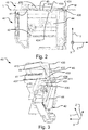
- the end piece 40 comprises a body portion 44 and a top wall 41 extending perpendicular to the body portion 44.
- the body portion 44 forms the surface of the end piece 40 that constitutes an end surface of the assembled screening device and that, in the mounted position of the screening device on a window, extends vertically and faces the side frame member 3b of the window.
- the top wall 41 forms a part of the end piece 40 that is intended to face the top frame member 3a of the window in the mounted position of the end piece and thus the screening device.
- the end piece 40 further comprises a resilient arm 43.
- the resilient arm 43 comprises a first end 435, a first section 431, a second section 432 and a second end 436 opposite to the first end 435.
- the end piece 40 is provided as a moulded part of a suitable material such as a plastic material.
- the resilient arm 43 may be moulded of a first suitable plastic material with a first hardness chosen to provide the necessary resilience, while the top wall 41 and for that matter the remaining parts of the end piece 40 may be made of a second plastic material with a second hardness being higher than the first hardness and moulded together with the resilient arm 43.
- the end piece 40 may me moulded of one and the same suitable plastic material.
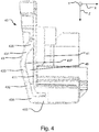
- the top wall 41 comprises a first surface 411 being parallel to and facing in the same direction as the body portion 44, a second surface 412 being perpendicular to first surface 411 and facing towards the body portion 44 and a third surface 413 being parallel and opposite to the second surface 412 - cf. Figs. 2 to 4 .
- the third surface 413 is perpendicular to first surface 411 and faces away from the body portion 44.
- the first surface 411 of the top wall 41 merges with or into the body portion 44 thus forming a continuous surface.
- the first end 435 and the second end 436 are connected to the top wall 41. It is also feasible than only one of the first end 435 and the second end 436 is connected to the top wall 41, while the other one of first end 435 and the second end 436 is not connected to the top wall 41.
- the resilient arm 43 is capable of flexing in both in a direction X towards the first surface 411 of the top wall and in a direction Y perpendicular to the first surface 411 of the top wall 41 and away from the body portion 44. Furthermore, the flexible arm 43 is biased towards an initial, un-flexed position, in which it is shown in Figs. 2-5 .
- the resilient arm 43 is sufficiently flexible and connected to the top wall 41 in such a manner that it is capable of flexing in the direction Y at least until reaching an outermost, i.e. maximally flexed, position where the resilient arm 43 is situated level with or possibly even beyond the second surface 412 of the top wall 41 in a direction towards the third surface 413.
- the resilient arm 43 further comprises an edge 437 facing the first surface 411 of the top wall 41.
- the edge 437 of the resilient arm 43 extends between the first end 435 and the second end 436.
- the edge 437 extends in a distance from the top wall 41. Thereby a gap 45 is provided between the resilient arm 43 and the top wall 41.
- the resilient arm 43 is sufficiently flexible and connected to the top wall 41 in such a manner that it is capable of flexing in the direction X at least until reaching an outermost, i.e. maximally flexed, position where the edge 437 of the resilient arm 43 is situated in abutment with the first surface 411 of the top wall 41.
- the first section 431 extends from the first end 435 away from the top wall 41, and more particularly the first surface 411 thereof.
- the first section 431 may extend sufficiently far away from the top wall 41 to allow the flexible arm 43 to abut or support on and, due to the resilience, also press against the side frame member 3b during installation of the screening arrangement. As this during installation will be the case at both opposite ends, the result is that the screening device will be centred or aligned during installation, thus further simplifying the installation process.
- the second section 432 extends back towards the top wall 41, and more particularly the first surface 411 thereof, to the second end 436.
- the first section 431 and the second section 432 are connected or meet at their respective ends opposite the first end 435 and the second end 436, respectively.
- An elbow or angle 433 is provided where the first section 431 and the second section 432 meet.
- the elbow 433 is shaped in such a manner as to provide a locking means or an engagement means 434 adapted for engaging with the locking means or engagement means 9 of the mounting bracket 6.
- the engagement means 434 is provided as a protrusion or nose on the resilient arm 43.
- the respective engagement means 434 and 9 provide for a snapping engagement between the end piece 40 and the mounting bracket 6, capable of locking the end piece 40 and the mounting bracket 6 together when mounting the screening arrangement on a window 1.
- the top frame member 3a of the window 1 is provided with a bevel of about 4°. Therefore, a wedge shaped space 10 is formed between the lower edge of the top frame member 3a of the window 1 and the top ledge 7 defining the upper line x 1 of the mounting bracket 6. Therefore, the end piece 40 is provided with a wedge shaped part 46 dimensioned to correspond to the said wedge shaped space 10. Referring to Fig. 2 , this wedge shaped part 46 is shown between the lines L and M. As may furthermore be seen the resilient arm 43 is in the embodiment shown provided with a general outline being substantially parallel with the line M and is thus adapted for substantially corresponding to the bevelling of the top frame member 3b of the window 1.
- the end piece when mounting the screening device, the end piece will be held between the top ledge 7 of the mounting bracket 6 and the lower edge of the top frame member 3a of the window 1 in such a way that it is substantially unable to move in the second direction h.
- This provides for a particularly simple installation process.
- one or both of the two end pieces 40 may optionally comprise a bottom flange 42 for guiding the end piece 40 and thereby the screening arrangement into position with respect to the mounting bracket 6 when mounting the screening device.
- the bottom flange 42 is thus adapted for guiding engagement with the bottom edge 8 of the mounting bracket ( Fig. 1 ).
- the bottom flange 42 may be provided in a manner known per se.
- the bottom flange 42 may be provided in the form of a further resilient arm, for instance being similar or identical to the resilient arm 43 described above, albeit mirror-inverted in comparison thereto.
- end piece 40 may comprise spring means for cooperation with a cord system of a further screening arrangement (not shown).
- Bringing the screening device of the screening arrangement to its mounted condition involves engaging the two end pieces 40 of the screening device with the two mounting brackets 6 mounted on opposing side members 3b of the frame 3 of the window 1.
- the screening device with its set of end pieces 40 is moved substantially in the third direction d ( Fig. 1 ) from a point distant from the pane 5 to a point proximate to the pane 5.
- the female engagement means 9 is able to cooperate with the male engagement means 434, so that it is possible to provide engagement between each end piece 40 and the respective mounting bracket 6 in at least a terminal position.
- the resilient arms 43 of the end pieces 40 of the screening device are aligned with the top ledges 7 of the respective mounting bracket 6.
- the resilient arms 43 of the end pieces 40 of the screening device are supported on the top ledges 7 of the respective mounting bracket 6.
- the screening device is moved in the third direction.
- the resilient arm 43 is flexed outwards in the direction Y to a position at least level with the second surface 412 of the top wall 41 to allow the flexible arm 43 to pass along the top ledge 7 of the mounting bracket 6.
- the end pieces 40 are locked to the mounting brackets 6 in the terminal position to attain the mounted condition.
- the male engagement means 434 in the form of a protrusion or nose on the resilient arm 43 interacts or engages with the shoulder or recess 9. This is obtained in that the flexible arm 43 flexes back to its initial, un-flexed position when the protrusion or nose 434 is aligned with the shoulder or recess 9.
Landscapes
- Engineering & Computer Science (AREA)
- Structural Engineering (AREA)
- Architecture (AREA)
- Civil Engineering (AREA)
- Window Of Vehicle (AREA)
Priority Applications (1)
| Application Number | Priority Date | Filing Date | Title |
|---|---|---|---|
| PL17208433T PL3354839T3 (pl) | 2017-01-31 | 2017-12-19 | Urządzenie zasłaniające i sposób instalowania wymienionego urządzenia zasłaniającego |
Applications Claiming Priority (1)
| Application Number | Priority Date | Filing Date | Title |
|---|---|---|---|
| DKPA201770058 | 2017-01-31 |
Publications (2)
| Publication Number | Publication Date |
|---|---|
| EP3354839A1 EP3354839A1 (en) | 2018-08-01 |
| EP3354839B1 true EP3354839B1 (en) | 2021-05-05 |
Family
ID=60673971
Family Applications (1)
| Application Number | Title | Priority Date | Filing Date |
|---|---|---|---|
| EP17208433.7A Active EP3354839B1 (en) | 2017-01-31 | 2017-12-19 | Screening apparatus and method of installing said screening apparatus |
Country Status (2)
| Country | Link |
|---|---|
| EP (1) | EP3354839B1 (pl) |
| PL (1) | PL3354839T3 (pl) |
Families Citing this family (1)
| Publication number | Priority date | Publication date | Assignee | Title |
|---|---|---|---|---|
| EP3869440B1 (en) | 2020-02-21 | 2025-07-23 | VKR Holding A/S | Method of directing a user to an online store |
Citations (1)
| Publication number | Priority date | Publication date | Assignee | Title |
|---|---|---|---|---|
| WO2005008013A1 (en) * | 2003-07-21 | 2005-01-27 | Vkr Holding A/S | Supporting means and screening device for use with such supporting means, and a window comprising such supporting means |
Family Cites Families (3)
| Publication number | Priority date | Publication date | Assignee | Title |
|---|---|---|---|---|
| SK119599A3 (en) * | 1997-08-12 | 2000-05-16 | Velux Ind As | Supporting means for screening device, a roof window and assembly of screening device for a roof window |
| JP4833332B2 (ja) * | 2006-03-27 | 2011-12-07 | ヴィーケーアール・ホールディング・アー・エス | 窓またはドアの枠内に設けられるスクリーニング装置を支持するブラケット部材、連結部材、窓またはドア、およびスクリーニング装置 |
| GB201217604D0 (en) * | 2012-10-02 | 2012-11-14 | Fourds Ltd | Screen assembly |
-
2017
- 2017-12-19 PL PL17208433T patent/PL3354839T3/pl unknown
- 2017-12-19 EP EP17208433.7A patent/EP3354839B1/en active Active
Patent Citations (1)
| Publication number | Priority date | Publication date | Assignee | Title |
|---|---|---|---|---|
| WO2005008013A1 (en) * | 2003-07-21 | 2005-01-27 | Vkr Holding A/S | Supporting means and screening device for use with such supporting means, and a window comprising such supporting means |
Also Published As
| Publication number | Publication date |
|---|---|
| EP3354839A1 (en) | 2018-08-01 |
| PL3354839T3 (pl) | 2021-11-02 |
Similar Documents
| Publication | Publication Date | Title |
|---|---|---|
| US12173536B2 (en) | Window balance assembly | |
| EP3205808B1 (en) | Screening arrangement with mounting brackets | |
| EP2692566B1 (en) | Dual end cap for a seal assembly | |
| CA2957295A1 (en) | Holding frame and method for producing same | |
| EP3354839B1 (en) | Screening apparatus and method of installing said screening apparatus | |
| US10519645B2 (en) | End wall for a gutter for surface drainage | |
| US20190145163A1 (en) | Screening arrangement with improved mounting bracket and end piece, window with such a mounting bracket and method of installing and uninstalling a screening arrangement in the window | |
| KR101581955B1 (ko) | 글레이징 비드 장착용 어댑터 어셈블리 | |
| CN106065755A (zh) | 用于玻璃固定边条的角连接件 | |
| CN219107370U (zh) | 一种边框和光伏组件 | |
| EP3266952B1 (en) | Assembly for cladding surfaces | |
| EP2011951B1 (en) | Bracket together with and for supporting a covering assembly | |
| JP4620538B2 (ja) | モール取付用クリップ | |
| KR20240002010U (ko) | 롤 블라인드 스냅의 좌우 균등설치용 브래킷 조립체 | |
| JP4781775B2 (ja) | 板状部に対する部材取付用具 | |
| EP2690246B1 (en) | A screening arrangement comprising means for mounting side rails and method of mounting such a screening arrangement | |
| JP2016138425A (ja) | エキスパンションジョイント装置 | |
| JPH1030379A (ja) | 押縁の取付構造 | |
| CH681820A5 (en) | Self-aligning, dome supporting assembly - has sloping frame and glazing support connected by spherical joint to vertical base connection member |
Legal Events
| Date | Code | Title | Description |
|---|---|---|---|
| PUAI | Public reference made under article 153(3) epc to a published international application that has entered the european phase |
Free format text: ORIGINAL CODE: 0009012 |
|
| STAA | Information on the status of an ep patent application or granted ep patent |
Free format text: STATUS: THE APPLICATION HAS BEEN PUBLISHED |
|
| AK | Designated contracting states |
Kind code of ref document: A1 Designated state(s): AL AT BE BG CH CY CZ DE DK EE ES FI FR GB GR HR HU IE IS IT LI LT LU LV MC MK MT NL NO PL PT RO RS SE SI SK SM TR |
|
| AX | Request for extension of the european patent |
Extension state: BA ME |
|
| STAA | Information on the status of an ep patent application or granted ep patent |
Free format text: STATUS: REQUEST FOR EXAMINATION WAS MADE |
|
| 17P | Request for examination filed |
Effective date: 20190201 |
|
| RBV | Designated contracting states (corrected) |
Designated state(s): AL AT BE BG CH CY CZ DE DK EE ES FI FR GB GR HR HU IE IS IT LI LT LU LV MC MK MT NL NO PL PT RO RS SE SI SK SM TR |
|
| STAA | Information on the status of an ep patent application or granted ep patent |
Free format text: STATUS: EXAMINATION IS IN PROGRESS |
|
| 17Q | First examination report despatched |
Effective date: 20190912 |
|
| GRAP | Despatch of communication of intention to grant a patent |
Free format text: ORIGINAL CODE: EPIDOSNIGR1 |
|
| STAA | Information on the status of an ep patent application or granted ep patent |
Free format text: STATUS: GRANT OF PATENT IS INTENDED |
|
| INTG | Intention to grant announced |
Effective date: 20210125 |
|
| RIN1 | Information on inventor provided before grant (corrected) |
Inventor name: BIRKKJAER, MARTIN |
|
| GRAS | Grant fee paid |
Free format text: ORIGINAL CODE: EPIDOSNIGR3 |
|
| GRAA | (expected) grant |
Free format text: ORIGINAL CODE: 0009210 |
|
| STAA | Information on the status of an ep patent application or granted ep patent |
Free format text: STATUS: THE PATENT HAS BEEN GRANTED |
|
| AK | Designated contracting states |
Kind code of ref document: B1 Designated state(s): AL AT BE BG CH CY CZ DE DK EE ES FI FR GB GR HR HU IE IS IT LI LT LU LV MC MK MT NL NO PL PT RO RS SE SI SK SM TR |
|
| REG | Reference to a national code |
Ref country code: GB Ref legal event code: FG4D |
|
| REG | Reference to a national code |
Ref country code: CH Ref legal event code: EP |
|
| REG | Reference to a national code |
Ref country code: AT Ref legal event code: REF Ref document number: 1390020 Country of ref document: AT Kind code of ref document: T Effective date: 20210515 |
|
| REG | Reference to a national code |
Ref country code: IE Ref legal event code: FG4D |
|
| REG | Reference to a national code |
Ref country code: DE Ref legal event code: R096 Ref document number: 602017037990 Country of ref document: DE |
|
| REG | Reference to a national code |
Ref country code: NL Ref legal event code: FP |
|
| REG | Reference to a national code |
Ref country code: LT Ref legal event code: MG9D |
|
| REG | Reference to a national code |
Ref country code: AT Ref legal event code: MK05 Ref document number: 1390020 Country of ref document: AT Kind code of ref document: T Effective date: 20210505 |
|
| PG25 | Lapsed in a contracting state [announced via postgrant information from national office to epo] |
Ref country code: FI Free format text: LAPSE BECAUSE OF FAILURE TO SUBMIT A TRANSLATION OF THE DESCRIPTION OR TO PAY THE FEE WITHIN THE PRESCRIBED TIME-LIMIT Effective date: 20210505 Ref country code: LT Free format text: LAPSE BECAUSE OF FAILURE TO SUBMIT A TRANSLATION OF THE DESCRIPTION OR TO PAY THE FEE WITHIN THE PRESCRIBED TIME-LIMIT Effective date: 20210505 Ref country code: BG Free format text: LAPSE BECAUSE OF FAILURE TO SUBMIT A TRANSLATION OF THE DESCRIPTION OR TO PAY THE FEE WITHIN THE PRESCRIBED TIME-LIMIT Effective date: 20210805 Ref country code: AT Free format text: LAPSE BECAUSE OF FAILURE TO SUBMIT A TRANSLATION OF THE DESCRIPTION OR TO PAY THE FEE WITHIN THE PRESCRIBED TIME-LIMIT Effective date: 20210505 Ref country code: HR Free format text: LAPSE BECAUSE OF FAILURE TO SUBMIT A TRANSLATION OF THE DESCRIPTION OR TO PAY THE FEE WITHIN THE PRESCRIBED TIME-LIMIT Effective date: 20210505 |
|
| PG25 | Lapsed in a contracting state [announced via postgrant information from national office to epo] |
Ref country code: GR Free format text: LAPSE BECAUSE OF FAILURE TO SUBMIT A TRANSLATION OF THE DESCRIPTION OR TO PAY THE FEE WITHIN THE PRESCRIBED TIME-LIMIT Effective date: 20210806 Ref country code: IS Free format text: LAPSE BECAUSE OF FAILURE TO SUBMIT A TRANSLATION OF THE DESCRIPTION OR TO PAY THE FEE WITHIN THE PRESCRIBED TIME-LIMIT Effective date: 20210905 Ref country code: LV Free format text: LAPSE BECAUSE OF FAILURE TO SUBMIT A TRANSLATION OF THE DESCRIPTION OR TO PAY THE FEE WITHIN THE PRESCRIBED TIME-LIMIT Effective date: 20210505 Ref country code: SE Free format text: LAPSE BECAUSE OF FAILURE TO SUBMIT A TRANSLATION OF THE DESCRIPTION OR TO PAY THE FEE WITHIN THE PRESCRIBED TIME-LIMIT Effective date: 20210505 Ref country code: RS Free format text: LAPSE BECAUSE OF FAILURE TO SUBMIT A TRANSLATION OF THE DESCRIPTION OR TO PAY THE FEE WITHIN THE PRESCRIBED TIME-LIMIT Effective date: 20210505 Ref country code: NO Free format text: LAPSE BECAUSE OF FAILURE TO SUBMIT A TRANSLATION OF THE DESCRIPTION OR TO PAY THE FEE WITHIN THE PRESCRIBED TIME-LIMIT Effective date: 20210805 Ref country code: PT Free format text: LAPSE BECAUSE OF FAILURE TO SUBMIT A TRANSLATION OF THE DESCRIPTION OR TO PAY THE FEE WITHIN THE PRESCRIBED TIME-LIMIT Effective date: 20210906 |
|
| PG25 | Lapsed in a contracting state [announced via postgrant information from national office to epo] |
Ref country code: EE Free format text: LAPSE BECAUSE OF FAILURE TO SUBMIT A TRANSLATION OF THE DESCRIPTION OR TO PAY THE FEE WITHIN THE PRESCRIBED TIME-LIMIT Effective date: 20210505 Ref country code: DK Free format text: LAPSE BECAUSE OF FAILURE TO SUBMIT A TRANSLATION OF THE DESCRIPTION OR TO PAY THE FEE WITHIN THE PRESCRIBED TIME-LIMIT Effective date: 20210505 Ref country code: CZ Free format text: LAPSE BECAUSE OF FAILURE TO SUBMIT A TRANSLATION OF THE DESCRIPTION OR TO PAY THE FEE WITHIN THE PRESCRIBED TIME-LIMIT Effective date: 20210505 Ref country code: RO Free format text: LAPSE BECAUSE OF FAILURE TO SUBMIT A TRANSLATION OF THE DESCRIPTION OR TO PAY THE FEE WITHIN THE PRESCRIBED TIME-LIMIT Effective date: 20210505 Ref country code: ES Free format text: LAPSE BECAUSE OF FAILURE TO SUBMIT A TRANSLATION OF THE DESCRIPTION OR TO PAY THE FEE WITHIN THE PRESCRIBED TIME-LIMIT Effective date: 20210505 Ref country code: SM Free format text: LAPSE BECAUSE OF FAILURE TO SUBMIT A TRANSLATION OF THE DESCRIPTION OR TO PAY THE FEE WITHIN THE PRESCRIBED TIME-LIMIT Effective date: 20210505 Ref country code: SK Free format text: LAPSE BECAUSE OF FAILURE TO SUBMIT A TRANSLATION OF THE DESCRIPTION OR TO PAY THE FEE WITHIN THE PRESCRIBED TIME-LIMIT Effective date: 20210505 |
|
| REG | Reference to a national code |
Ref country code: DE Ref legal event code: R097 Ref document number: 602017037990 Country of ref document: DE |
|
| PLBE | No opposition filed within time limit |
Free format text: ORIGINAL CODE: 0009261 |
|
| STAA | Information on the status of an ep patent application or granted ep patent |
Free format text: STATUS: NO OPPOSITION FILED WITHIN TIME LIMIT |
|
| 26N | No opposition filed |
Effective date: 20220208 |
|
| PG25 | Lapsed in a contracting state [announced via postgrant information from national office to epo] |
Ref country code: IS Free format text: LAPSE BECAUSE OF FAILURE TO SUBMIT A TRANSLATION OF THE DESCRIPTION OR TO PAY THE FEE WITHIN THE PRESCRIBED TIME-LIMIT Effective date: 20210905 Ref country code: AL Free format text: LAPSE BECAUSE OF FAILURE TO SUBMIT A TRANSLATION OF THE DESCRIPTION OR TO PAY THE FEE WITHIN THE PRESCRIBED TIME-LIMIT Effective date: 20210505 |
|
| PG25 | Lapsed in a contracting state [announced via postgrant information from national office to epo] |
Ref country code: MC Free format text: LAPSE BECAUSE OF FAILURE TO SUBMIT A TRANSLATION OF THE DESCRIPTION OR TO PAY THE FEE WITHIN THE PRESCRIBED TIME-LIMIT Effective date: 20210505 Ref country code: IT Free format text: LAPSE BECAUSE OF FAILURE TO SUBMIT A TRANSLATION OF THE DESCRIPTION OR TO PAY THE FEE WITHIN THE PRESCRIBED TIME-LIMIT Effective date: 20210505 |
|
| REG | Reference to a national code |
Ref country code: CH Ref legal event code: PL |
|
| REG | Reference to a national code |
Ref country code: BE Ref legal event code: MM Effective date: 20211231 |
|
| PG25 | Lapsed in a contracting state [announced via postgrant information from national office to epo] |
Ref country code: LU Free format text: LAPSE BECAUSE OF NON-PAYMENT OF DUE FEES Effective date: 20211219 Ref country code: IE Free format text: LAPSE BECAUSE OF NON-PAYMENT OF DUE FEES Effective date: 20211219 |
|
| PG25 | Lapsed in a contracting state [announced via postgrant information from national office to epo] |
Ref country code: BE Free format text: LAPSE BECAUSE OF NON-PAYMENT OF DUE FEES Effective date: 20211231 |
|
| PG25 | Lapsed in a contracting state [announced via postgrant information from national office to epo] |
Ref country code: LI Free format text: LAPSE BECAUSE OF NON-PAYMENT OF DUE FEES Effective date: 20211231 Ref country code: CH Free format text: LAPSE BECAUSE OF NON-PAYMENT OF DUE FEES Effective date: 20211231 |
|
| PG25 | Lapsed in a contracting state [announced via postgrant information from national office to epo] |
Ref country code: HU Free format text: LAPSE BECAUSE OF FAILURE TO SUBMIT A TRANSLATION OF THE DESCRIPTION OR TO PAY THE FEE WITHIN THE PRESCRIBED TIME-LIMIT; INVALID AB INITIO Effective date: 20171219 |
|
| PG25 | Lapsed in a contracting state [announced via postgrant information from national office to epo] |
Ref country code: CY Free format text: LAPSE BECAUSE OF FAILURE TO SUBMIT A TRANSLATION OF THE DESCRIPTION OR TO PAY THE FEE WITHIN THE PRESCRIBED TIME-LIMIT Effective date: 20210505 |
|
| PG25 | Lapsed in a contracting state [announced via postgrant information from national office to epo] |
Ref country code: MK Free format text: LAPSE BECAUSE OF FAILURE TO SUBMIT A TRANSLATION OF THE DESCRIPTION OR TO PAY THE FEE WITHIN THE PRESCRIBED TIME-LIMIT Effective date: 20210505 |
|
| PG25 | Lapsed in a contracting state [announced via postgrant information from national office to epo] |
Ref country code: MT Free format text: LAPSE BECAUSE OF FAILURE TO SUBMIT A TRANSLATION OF THE DESCRIPTION OR TO PAY THE FEE WITHIN THE PRESCRIBED TIME-LIMIT Effective date: 20210505 |
|
| PG25 | Lapsed in a contracting state [announced via postgrant information from national office to epo] |
Ref country code: TR Free format text: LAPSE BECAUSE OF FAILURE TO SUBMIT A TRANSLATION OF THE DESCRIPTION OR TO PAY THE FEE WITHIN THE PRESCRIBED TIME-LIMIT Effective date: 20210505 |
|
| PGFP | Annual fee paid to national office [announced via postgrant information from national office to epo] |
Ref country code: NL Payment date: 20251112 Year of fee payment: 9 |
|
| PGFP | Annual fee paid to national office [announced via postgrant information from national office to epo] |
Ref country code: DE Payment date: 20251104 Year of fee payment: 9 |
|
| PGFP | Annual fee paid to national office [announced via postgrant information from national office to epo] |
Ref country code: GB Payment date: 20251114 Year of fee payment: 9 |
|
| PGFP | Annual fee paid to national office [announced via postgrant information from national office to epo] |
Ref country code: FR Payment date: 20251124 Year of fee payment: 9 |
|
| PGFP | Annual fee paid to national office [announced via postgrant information from national office to epo] |
Ref country code: PL Payment date: 20251117 Year of fee payment: 9 |