EP3354806B1 - Sealing gasket for sanitary fitting for mounting in a through hole of a sanitary installation - Google Patents
Sealing gasket for sanitary fitting for mounting in a through hole of a sanitary installation Download PDFInfo
- Publication number
- EP3354806B1 EP3354806B1 EP18152215.2A EP18152215A EP3354806B1 EP 3354806 B1 EP3354806 B1 EP 3354806B1 EP 18152215 A EP18152215 A EP 18152215A EP 3354806 B1 EP3354806 B1 EP 3354806B1
- Authority
- EP
- European Patent Office
- Prior art keywords
- sealing gasket
- mounting
- sanitary
- contact surface
- stud bolt
- Prior art date
- Legal status (The legal status is an assumption and is not a legal conclusion. Google has not performed a legal analysis and makes no representation as to the accuracy of the status listed.)
- Active
Links
Images


Classifications
-
- E—FIXED CONSTRUCTIONS
- E03—WATER SUPPLY; SEWERAGE
- E03C—DOMESTIC PLUMBING INSTALLATIONS FOR FRESH WATER OR WASTE WATER; SINKS
- E03C1/00—Domestic plumbing installations for fresh water or waste water; Sinks
- E03C1/02—Plumbing installations for fresh water
- E03C1/04—Water-basin installations specially adapted to wash-basins or baths
- E03C1/0401—Fixing a tap to the sanitary appliance or to an associated mounting surface, e.g. a countertop
Definitions
- the invention relates to a sealing gasket for a sanitary fitting, wherein the sealing gasket is configured to be interposed between a contact surface of a housing base of the sanitary fitting and a support surface around a mounting through hole of a sanitary installation.
- the invention further relates to a centering sealing gasket and a sanitary fitting using such a sealing gasket.
- a sanitary fitting usually comprises water connections protruding from a housing base of the sanitary fitting for connection of the sanitary fitting to the domestic plumbing lines. Furthermore such a sanitary fitting comprises a mounting stud bolt, which has a male screw thread and protrudes from the housing base for mounting purposes.
- the mounting stud bolt and the water connections are inserted into a through hole of a sanitary installation like e.g. a washing table, a washbasin, a washstand, a wall installation or a pedestal installation.
- a retaining element is fastened on the mounting stud bolt on the opposite side of the mounting through hole. Due to the fastening of the retaining element a contact surface of the housing base is pressed against a support surface around the mounting through hole and the sanitary fitting gets fixed at the sanitary installation.
- a sealing gasket is interposed between the contact surface and the support surface.
- Such a sealing gasket also compensates for any unevenness of the support surface of the sanitary installation which is necessary because the sanitary installations are usually made of ceramics having a rather undefined surface flatness.
- the sealing gaskets used for this purpose are usually rotationally symmetric rings or the like. However, it turned out that it is sometimes difficult to properly fix the sanitary fitting using such rotationally symmetric sealing gaskets.
- A1 sealing gasket for a sanitary fitting is known which is made of one piece in an injection molding process including two material components.
- a centering sleeve part of the sealing gasket is made of a hard material and an abutment part surrounding the centering sleeve part is made of a soft material.
- the sealing gasket is rotationally symmetric with respect to the fastening forces involved.
- the sealing gasket comprises an identically inclined centering sleeve and therefore has a generally asymmetric appearance.
- the foot print of the sealing gasket in between the contact surface of the housing base and the support surface around the mounting through hole is symmetric.
- the mounting stud bolt is usually arranged eccentric with respect to the contact surface of the housing base in order to provide sufficient space for the connection of the water connections inside the housing base.
- the distribution of forces exerted on the sealing gasket between the contact surface and the support is imbalanced, because the distribution of the exerted forces is defined by a system of lever arms of different lengths. Therefore, the part of the sealing gasket contacting the side of the housing base corresponding to the shorter lever arm (usually the side pointing to the backside of the sanitary fitting) is compressed stronger than the remaining part corresponding to the longer lever arm. Accordingly, the sanitary fitting tilts to the side of the short lever arm and the housing base finally contacts the sanitary installation in a single point and exerts a high point load on the sanitary installation usually made of ceramics.
- a first part of the sealing gasket yields to a lesser extent than a second part of the sealing gasket under the load of forces exerted by the contact surface and the support surface on the sealing gasket.
- the first part of the sealing gasket is stiffer than the second part.
- the sanitary fitting does not tilt during fastening and the housing base and the contact surface are flatly pressed on the sealing gasket.
- this results in a higher resistance against twisting of the sanitary fitting because the sanitary fitting mainly resides on the sealing gasket generally having a higher friction coefficient than only a small metallic backside edge of the housing base.
- the sealing gasket may have any usually used general shape like substantially a ring shape, an elliptical shape, a rectangular shape or the like.
- Asymmetric shapes are used, although in the context of this invention an asymmetric sealing gasket mainly refers to the distribution of the counterforces exerted by the sealing gasket when interposed between the contact surface and the support surface.
- the sealing gasket may or may not include further parts which are not relevant for the distribution of the forces.
- the first part of the sealing gasket has way have a different cross section than the second part.
- a different cross section provides a different stiffness even if the same material is used for both parts of the sealing gasket.
- the cross section of the first part may have a larger area than the cross section of the second part. Therefore, the first part of the sealing gasket is more massive than the second part of the sealing gasket and consequently is stiffer if made from the same material.
- the first part of the sealing gasket may comprise a strengthening element, in particular ribs or headings.
- the stiffness of the different parts of the sealing gasket is not only influenced by the overall area of the cross section but also by its shape. Therefore, the first part of the sealing gasket may be stiffened by providing strengthening elements which add additional area to the cross section area or which are provided by a reshaped cross section having the same cross section area than the second part.
- a sealing gasket not according to the invention may have a substantially rotational symmetric geometry but the first part is made of a material with a lower elasticity than the material of the second part.
- the sealing gasket may be provided with different shore hardness on the first and the second parts. This may be achieved for example by a subsequent thermal hardening of the first part of an originally symmetric sealing gasket.
- the eccentric arrangement of the mounting stud bolt with respect to the contact surface defines two lever arms having different lengths. Therefore, it is advantageous if the stiffness of the first part and the stiffness of the second part of the sealing gasket are chosen such that counter forces exerted by the first and the second part compensate for the different lengths of the lever arms. This can be achieved by using the ratio of the lever arm lengths to determine the ratio of the stiffness values of the first and second parts.
- the sealing gasket may comprise an orientation element which allows to properly orientate the sealing gasket with respect to the eccentric arrangement of the mounting stud bolt.
- an orientation element may for example be a lug having a through hole for the mounting stud bolt and protruding inwards from the sealing gasket.
- first part of the sealing gasket circumferentially runs along an angle of less than approximately 120°, in particular 90°, in particular 40°, and the second part respectively runs along an angle of at least approximately 240°, in particular 270°, in particular 320°.
- the object of the invention is achieved by a sealing gasket configured to be interposed between a contact surface of a housing base of a sanitary fitting and a support surface around a mounting through hole of a sanitary installation, wherein the sealing gasket is asymmetric such that a first part of the sealing gasket yields to a lesser extent than a second part of the sealing gasket under the load of forces exerted by the contact surface and the support surface on the sealing gasket when a retaining element is fastened on a mounting stud bolt of the sanitary fitting.
- the advantageous features mentioned above for the sanitary fitting also apply correspondingly to the sealing gasket.
- Figure 1 shows sanitary fitting 10 mounted to a mounting plate 12 of washing basin as an exemplary sanitary installation.
- the mounting plate 12 of the washing basin comprises a mounting through hole 14.
- the region adjacent to the mounting through hole 14 defines a support surface 16, which substantially supports a housing base 18 of the sanitary fitting 10.
- the housing base 18 of the sanitary fitting 10 often has a sleeve shape comprising an inner shoulder recessing slightly in axial direction and thereby providing a contact surface 20 which is oriented towards the mounting plate 12 and configured to receive a sealing gasket 34.
- the contact surface 20 has a substantially ring shaped foot print in accordance with the general layout of the housing base 18.
- the sanitary fitting 10 For connection of the sanitary fitting 10 to domestic plumbing lines the sanitary fitting 10 comprises water connection lines 22 and 24 protruding from the housing base 18.
- the sanitary fitting 10 comprises a mounting stud bolt 26 protruding from the housing base 18 as an integrated part of the sanitary fitting 10 or screwed into the sanitary fitting 10.
- the mounting stud bolt 26 comprises a male screw thread on which a retaining element 28 may be fastened against the mounting plate 12 using a securing nut 30.
- the mounting stud bolt 26 is arranged eccentrically with respect to the contact surface 20 of the housing base 18.
- the mounting stud bolt 26 is radially shifted towards the backside of the sanitary fitting 10, namely the side opposite to a protruding water outlet 32.
- the sealing gasket 34 is interposed between the contact surface 20 of the housing base 18 and the support surface 16 around the mounting through hole 14 of the mounting plate 12.
- the sealing gasket 34 gets compressed stronger by a backside edge 36 of the housing base 18 than by a front edge 38 of the housing base 18. Consequently, the backside edge 36 contacts the mounting plate 12 long before the front edge 38 resulting in a tilt of the sanitary fitting 10 towards the backside edge 34 and in a difficult fastening of the sanitary fitting 10 using a sealing gasket 34 according to the state of the art.
- Figures 3-7 show an exemplary sealing gasket 34 according to the present invention having a substantially round ring shape with a flat top surface 40 from which a circumferential sleeve 42 projects axially on the outer circumference. Thereby, a free shoulder 44 is provided pointing towards the inside, which runs along the circumference in an angular section of approximately 320°.
- the sealing gasket 34 is more massive such that the space above the shoulder 44 next to the circumferential sleeve 42 is filled.
- Figure 6 showing a cross section of the sealing gasket 34.
- the radial cross section of the sealing gasket 34 within the 40° angular section, which defines a first part 46 of the sealing gasket 34 has an approximately rectangular, in particular quadratic, shape.
- the cross section within the other 320° angular section, which defines a second part 48 of the sealing gasket 34 has substantially an L-shape. Therefore, the area of the cross section of the first part 46 is larger than the cross section of the second part 48. Consequently, the first part 46 is stiffer than the second part 48.
- the sealing gasket 34 comprises a lug 50 which radially protrudes inwards from the general ring shape and which provides a through hole 52 for receiving the mounting stud bolt 26 of the sanitary fitting 10.
- the first part 46 of the sealing gasket 34 yields to a lesser extent than a second part 48 of the sealing gasket 34 under the load of forces exerted by the contact surface 20 and the support surface 16 when the retaining element 28 is fastened on the mounting stud bolt 26. Accordingly, the sealing gasket 34 is more evenly compressed even though the mounting stud bolt 26 is arranged eccentric with respect to the contact surface 20 of the housing base 18.
- FIGS. 7-10 show a second embodiment of the sealing gasket 34, wherein elements having the same structural function have the same reference number.
- the sealing gasket 34 comprises a frustoconical centering shoulder 80 recessing inwards from the flat top surface 40. Furthermore, the top surface 40 is surrounded on its circumference by a small sealing lip 81 protruding axial upwards from the top surface 40.
- the sealing gasket 34 comprises a centering apron 82 provided on radially inwards and protruding downwards for centering the sealing gasket 34 inside the mounting through hole 14.
- the first part 46 is formed by a filled space between the centering apron 82 and the circumferential sleeve 42.
Landscapes
- Health & Medical Sciences (AREA)
- Life Sciences & Earth Sciences (AREA)
- Engineering & Computer Science (AREA)
- Hydrology & Water Resources (AREA)
- Public Health (AREA)
- Water Supply & Treatment (AREA)
- Gasket Seals (AREA)
Description
- The invention relates to a sealing gasket for a sanitary fitting, wherein the sealing gasket is configured to be interposed between a contact surface of a housing base of the sanitary fitting and a support surface around a mounting through hole of a sanitary installation. The invention further relates to a centering sealing gasket and a sanitary fitting using such a sealing gasket.
- A sanitary fitting usually comprises water connections protruding from a housing base of the sanitary fitting for connection of the sanitary fitting to the domestic plumbing lines. Furthermore such a sanitary fitting comprises a mounting stud bolt, which has a male screw thread and protrudes from the housing base for mounting purposes.
- During the installation of such a sanitary fitting, the mounting stud bolt and the water connections are inserted into a through hole of a sanitary installation like e.g. a washing table, a washbasin, a washstand, a wall installation or a pedestal installation. In a next step, a retaining element is fastened on the mounting stud bolt on the opposite side of the mounting through hole. Due to the fastening of the retaining element a contact surface of the housing base is pressed against a support surface around the mounting through hole and the sanitary fitting gets fixed at the sanitary installation.
- In order to prevent splash water from flowing in between the contact surface of the sanitary fitting and the support surface of the sanitary installation and onward through the mounting through hole a sealing gasket is interposed between the contact surface and the support surface. Such a sealing gasket also compensates for any unevenness of the support surface of the sanitary installation which is necessary because the sanitary installations are usually made of ceramics having a rather undefined surface flatness.
- The sealing gaskets used for this purpose are usually rotationally symmetric rings or the like. However, it turned out that it is sometimes difficult to properly fix the sanitary fitting using such rotationally symmetric sealing gaskets.
- From
DE 10 2010 044 420 A1 sealing gasket for a sanitary fitting is known which is made of one piece in an injection molding process including two material components. A centering sleeve part of the sealing gasket is made of a hard material and an abutment part surrounding the centering sleeve part is made of a soft material. However, the sealing gasket is rotationally symmetric with respect to the fastening forces involved. - From
DE 93 04 056 U1 a flat, ring-shaped sealing gasket is known which is radially broader in a first angular part of the ring than in second angular part. - From
EP 0 193 437 A1 a sanitary fitting with an inclined housing body is known. The sealing gasket comprises an identically inclined centering sleeve and therefore has a generally asymmetric appearance. However, the foot print of the sealing gasket in between the contact surface of the housing base and the support surface around the mounting through hole is symmetric. - It is therefore an object of the present invention to provide a sealing gasket for a sanitary fitting which allows a better fastening of the sanitary fitting. In particular, it is an object of the invention to provide a way to more uniformly distribute the forces exerted on the sealing gasket throughout the fastening of the retaining element.
- This object is achieved by a sealing gasket according to claim 1.
- The inventor has realized that the mounting stud bolt is usually arranged eccentric with respect to the contact surface of the housing base in order to provide sufficient space for the connection of the water connections inside the housing base. However, due to the eccentric arrangement of the mounting stud bolt the distribution of forces exerted on the sealing gasket between the contact surface and the support is imbalanced, because the distribution of the exerted forces is defined by a system of lever arms of different lengths. Therefore, the part of the sealing gasket contacting the side of the housing base corresponding to the shorter lever arm (usually the side pointing to the backside of the sanitary fitting) is compressed stronger than the remaining part corresponding to the longer lever arm. Accordingly, the sanitary fitting tilts to the side of the short lever arm and the housing base finally contacts the sanitary installation in a single point and exerts a high point load on the sanitary installation usually made of ceramics.
- By using a asymmetric sealing gasket one may counteract on this imbalance by providing a larger reaction force for the smaller lever arm and a smaller reaction force for the longer lever arm. Generally speaking, a first part of the sealing gasket yields to a lesser extent than a second part of the sealing gasket under the load of forces exerted by the contact surface and the support surface on the sealing gasket.
- Or otherwise stated, the first part of the sealing gasket is stiffer than the second part. Thereby, the sanitary fitting does not tilt during fastening and the housing base and the contact surface are flatly pressed on the sealing gasket. This results in a reduced point load on the sanitary installation which may prevent cracking of any ceramic parts. Furthermore, this results in a higher resistance against twisting of the sanitary fitting, because the sanitary fitting mainly resides on the sealing gasket generally having a higher friction coefficient than only a small metallic backside edge of the housing base.
- Because the general shape of the sealing gasket depends on the shape of the housing base of the sanitary fitting, the sealing gasket may have any usually used general shape like substantially a ring shape, an elliptical shape, a rectangular shape or the like. Asymmetric shapes are used, although in the context of this invention an asymmetric sealing gasket mainly refers to the distribution of the counterforces exerted by the sealing gasket when interposed between the contact surface and the support surface.
- The sealing gasket may or may not include further parts which are not relevant for the distribution of the forces.
- Furthermore, the first part of the sealing gasket has way have a different cross section than the second part. A different cross section provides a different stiffness even if the same material is used for both parts of the sealing gasket.
- Furthermore, the cross section of the first part may have a larger area than the cross section of the second part. Therefore, the first part of the sealing gasket is more massive than the second part of the sealing gasket and consequently is stiffer if made from the same material.
- Furthermore, the first part of the sealing gasket may comprise a strengthening element, in particular ribs or headings. The stiffness of the different parts of the sealing gasket is not only influenced by the overall area of the cross section but also by its shape. Therefore, the first part of the sealing gasket may be stiffened by providing strengthening elements which add additional area to the cross section area or which are provided by a reshaped cross section having the same cross section area than the second part.
- Furthermore, a sealing gasket not according to the invention may have a substantially rotational symmetric geometry but the first part is made of a material with a lower elasticity than the material of the second part. In particular, the sealing gasket may be provided with different shore hardness on the first and the second parts. This may be achieved for example by a subsequent thermal hardening of the first part of an originally symmetric sealing gasket.
- The eccentric arrangement of the mounting stud bolt with respect to the contact surface defines two lever arms having different lengths. Therefore, it is advantageous if the stiffness of the first part and the stiffness of the second part of the sealing gasket are chosen such that counter forces exerted by the first and the second part compensate for the different lengths of the lever arms. This can be achieved by using the ratio of the lever arm lengths to determine the ratio of the stiffness values of the first and second parts.
- Furthermore, the sealing gasket may comprise an orientation element which allows to properly orientate the sealing gasket with respect to the eccentric arrangement of the mounting stud bolt. Such an orientation element may for example be a lug having a through hole for the mounting stud bolt and protruding inwards from the sealing gasket.
- Furthermore, the first part of the sealing gasket circumferentially runs along an angle of less than approximately 120°, in particular 90°, in particular 40°, and the second part respectively runs along an angle of at least approximately 240°, in particular 270°, in particular 320°.
- Regarding the sealing gasket the object of the invention is achieved by a sealing gasket configured to be interposed between a contact surface of a housing base of a sanitary fitting and a support surface around a mounting through hole of a sanitary installation, wherein the sealing gasket is asymmetric such that a first part of the sealing gasket yields to a lesser extent than a second part of the sealing gasket under the load of forces exerted by the contact surface and the support surface on the sealing gasket when a retaining element is fastened on a mounting stud bolt of the sanitary fitting. The advantageous features mentioned above for the sanitary fitting also apply correspondingly to the sealing gasket.
- Various features and advantages of the invention may be more readily understood with reference to the following detailed description which refers to the following drawings in which:
- Figure 1
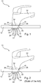
- shows a side view of a sanitary fitting mounted on a sanitary installation by interposition of a sealing gasket;
- Figure 2
- shows a side view of a sanitary fitting having a sealing gasket according to the state of the art when a retaining element is fastened;
- Figure 3
- shows a perspective top view of a sealing gasket according to the invention;
- Figure 4
- shows a perspective bottom view of the sealing gasket according to the invention;
- Figure 5
- shows a bottom view of the sealing gasket;
- Figure 6
- shows a section along cut line A-A shown in
Figure 5 ; - Figure 7
- shows a perspective top view of a sealing gasket according to a second embodiment;
- Figure 8
- shows a perspective bottom view of the sealing gasket of
Figure 7 ; - Figure 9
- shows a bottom view of the sealing gasket of
Figure 7 ; - Figure 10
- shows a section along cut line A-A shown in
Figure 9 ; -
Figure 1 showssanitary fitting 10 mounted to a mountingplate 12 of washing basin as an exemplary sanitary installation. - For this purpose the mounting
plate 12 of the washing basin comprises a mounting throughhole 14. The region adjacent to the mounting throughhole 14 defines asupport surface 16, which substantially supports ahousing base 18 of thesanitary fitting 10. - The
housing base 18 of thesanitary fitting 10 often has a sleeve shape comprising an inner shoulder recessing slightly in axial direction and thereby providing acontact surface 20 which is oriented towards the mountingplate 12 and configured to receive a sealinggasket 34. Thecontact surface 20 has a substantially ring shaped foot print in accordance with the general layout of thehousing base 18. - For connection of the
sanitary fitting 10 to domestic plumbing lines thesanitary fitting 10 compriseswater connection lines housing base 18. - Furthermore, the
sanitary fitting 10 comprises a mountingstud bolt 26 protruding from thehousing base 18 as an integrated part of thesanitary fitting 10 or screwed into thesanitary fitting 10. The mountingstud bolt 26 comprises a male screw thread on which a retainingelement 28 may be fastened against the mountingplate 12 using a securingnut 30. - However, because of the space needed for the
water connection lines stud bolt 26 is arranged eccentrically with respect to thecontact surface 20 of thehousing base 18. In particular, the mountingstud bolt 26 is radially shifted towards the backside of thesanitary fitting 10, namely the side opposite to a protrudingwater outlet 32. - In order to prevent spray water from flowing in between the
housing base 18 and the mountingplate 12, the sealinggasket 34 is interposed between thecontact surface 20 of thehousing base 18 and thesupport surface 16 around the mounting throughhole 14 of the mountingplate 12. - As it can be seen from
Figure 2 which shows the use of a sealinggasket 34 according to the state of the art, the forces, which are exerted by thecontact surface 20 and thesupport surface 16 on the sealinggasket 34 when the retainingelement 28 is fastened, are distributed unequally because of the different lengths of the lever arms A and B with respect to the mountingstud bolt 26. - Therefore, the sealing
gasket 34 gets compressed stronger by abackside edge 36 of thehousing base 18 than by afront edge 38 of thehousing base 18. Consequently, thebackside edge 36 contacts the mountingplate 12 long before thefront edge 38 resulting in a tilt of thesanitary fitting 10 towards thebackside edge 34 and in a difficult fastening of thesanitary fitting 10 using a sealinggasket 34 according to the state of the art. - Therefore,
Figures 3-7 show anexemplary sealing gasket 34 according to the present invention having a substantially round ring shape with a flattop surface 40 from which acircumferential sleeve 42 projects axially on the outer circumference. Thereby, afree shoulder 44 is provided pointing towards the inside, which runs along the circumference in an angular section of approximately 320°. - Along the remaining 40° angular section of the sealing
gasket 34 the sealinggasket 34 is more massive such that the space above theshoulder 44 next to thecircumferential sleeve 42 is filled. This can be best seen fromFigure 6 showing a cross section of the sealinggasket 34. The radial cross section of the sealinggasket 34 within the 40° angular section, which defines afirst part 46 of the sealinggasket 34, has an approximately rectangular, in particular quadratic, shape. In contrast, the cross section within the other 320° angular section, which defines asecond part 48 of the sealinggasket 34, has substantially an L-shape. Therefore, the area of the cross section of thefirst part 46 is larger than the cross section of thesecond part 48. Consequently, thefirst part 46 is stiffer than thesecond part 48. - Furthermore, the sealing
gasket 34 comprises alug 50 which radially protrudes inwards from the general ring shape and which provides a throughhole 52 for receiving the mountingstud bolt 26 of thesanitary fitting 10. - When mounting the
sanitary fitting 10 with the sealinggasket 34 according to the invention, thefirst part 46 of the sealinggasket 34 yields to a lesser extent than asecond part 48 of the sealinggasket 34 under the load of forces exerted by thecontact surface 20 and thesupport surface 16 when the retainingelement 28 is fastened on the mountingstud bolt 26. Accordingly, the sealinggasket 34 is more evenly compressed even though the mountingstud bolt 26 is arranged eccentric with respect to thecontact surface 20 of thehousing base 18. -
Figures 7-10 show a second embodiment of the sealinggasket 34, wherein elements having the same structural function have the same reference number. - As can be seen from
Figures 7 and 10 the sealinggasket 34 according to the second embodiment comprises a frustoconical centeringshoulder 80 recessing inwards from the flattop surface 40. Furthermore, thetop surface 40 is surrounded on its circumference by asmall sealing lip 81 protruding axial upwards from thetop surface 40. - Furthermore, the sealing
gasket 34 comprises a centeringapron 82 provided on radially inwards and protruding downwards for centering the sealinggasket 34 inside the mounting throughhole 14. - In this embodiment of the sealing
gasket 34 thefirst part 46 is formed by a filled space between the centeringapron 82 and thecircumferential sleeve 42.
Claims (9)
- A sealing gasket (34) for a sanitary fitting (10), wherein the sealing gasket (34) is configured to be interposed between a contact surface (20) of a housing base (18) of the sanitary fitting (10) and a support surface (16) around a mounting through hole (14) of a sanitary installation (12), wherein a mounting stud bolt (14) is arranged eccentrically with respect to the contact surface (20) at the housing base (18), whereina) the sealing gasket (34) is asymmetric such that a first part (46) of the sealing gasket (34) yields to a lesser extent than a second part (48) of the sealing gasket (34) under the load of forces exerted by the contact surface (20) and the support surface (16) on the sealing gasket (34) when a retaining element (28) is fastened on the mounting stud bolt (26) of the sanitary fitting (10), wherein the first part (46) of the sealing gasket (34) has a radial cross section which has an approximately rectangular shape and wherein the second part (48) of the sealing gasket (34) has a cross section which has substantially an L-shape and wherein the first part (46) of the sealing gasket (34) circumferentially runs along an angle of less than approximately 120°, in particular 90°, in particular 40°, and the second part (48) respectively runs along an angle of at least approximately 240°, in particular 270°, in particular 320°.
- The sealing gasket according to claim 1, wherein the first part (46) of the sealing gasket (34) is stiffer than the second part (48).
- The sealing gasket according to any of the preceding claims, wherein the first part (46) of the sealing gasket (34) has a different cross section than the second part (48).
- The sealing gasket according to claim 3, wherein the cross section of the first part (46) has a larger area than the cross section of the second part (48).
- The sealing gasket according to any of the preceding claims, wherein the first part (46) of the sealing gasket (34) comprises a strengthening element, in particular ribs or headings.
- The sealing gasket according to any of the preceding claims, wherein the eccentric arrangement of the mounting stud bolt (46) with respect to the contact surface (20) defines two lever arms (A, B) having different lengths and wherein the stiffness of the first part (46) and the stiffness of the second part (48) of the sealing gasket (34) are chosen such that counter forces exerted by the first part (46) and the second part (48) compensate for the different lengths of the lever arms (A, B).
- The sealing gasket according to any of the preceding claims, wherein the sealing gasket (34) comprises an orientation element (50) which allows to properly orientate the sealing gasket (34) with respect to the eccentric arrangement of the mounting stud bolt (26).
- A centering sealing gasket (34) comprisinga) a sealing gasket (34) according to any of the preceding claims andb) a frustoconical centering shoulder (80) recessing inwards from the flat top surface (40) and a centering apron (82) provided radially inwards and protruding downwards from the sealing gasket (34) for centering the centering sealing gasket (34) inside the mounting through hole (14).
- A sanitary fitting (10) comprisinga) a housing base (18) having a contact surface (20);b) a mounting stud bolt (26) configured to be inserted into a mounting through hole (14) of a sanitary installation (12), wherein the mounting stud bolt (14) is arranged eccentrically with respect to the contact surface (20) at the housing base (18);c) a sealing gasket (34) respectively a centering sealing gasket (34) according to any of the preceding claims configured to be interposed between the contact surface (20) of the housing base (18) and a support surface (16) around the mounting through hole (14);d) a retaining element (28) configured to be fastened on the mounting stud bolt (26) on a side of mounting through hole (14) of the sanitary installation (12) opposite to the housing base (18) in order to fasten the sanitary fitting (10) at the sanitary installation (12).
Applications Claiming Priority (1)
| Application Number | Priority Date | Filing Date | Title |
|---|---|---|---|
| DE102017101900.6A DE102017101900B4 (en) | 2017-01-31 | 2017-01-31 | Sanitary fitting and seal for fastening in a through hole of a sanitary installation |
Publications (2)
| Publication Number | Publication Date |
|---|---|
| EP3354806A1 EP3354806A1 (en) | 2018-08-01 |
| EP3354806B1 true EP3354806B1 (en) | 2021-09-01 |
Family
ID=61005753
Family Applications (1)
| Application Number | Title | Priority Date | Filing Date |
|---|---|---|---|
| EP18152215.2A Active EP3354806B1 (en) | 2017-01-31 | 2018-01-18 | Sealing gasket for sanitary fitting for mounting in a through hole of a sanitary installation |
Country Status (4)
| Country | Link |
|---|---|
| EP (1) | EP3354806B1 (en) |
| CN (1) | CN108374458B (en) |
| DE (1) | DE102017101900B4 (en) |
| ES (1) | ES2896129T3 (en) |
Family Cites Families (10)
| Publication number | Priority date | Publication date | Assignee | Title |
|---|---|---|---|---|
| FR2577254B1 (en) * | 1985-02-08 | 1987-04-10 | Presto Robinets Sa | IMPROVEMENT IN DEVICES FOR FIXING TAPS ON A WALL |
| DE9304056U1 (en) * | 1993-03-19 | 1993-05-13 | Sanha Kaimer Kg, 4300 Essen | Single lever mixer tap |
| DE4308746A1 (en) * | 1993-03-19 | 1994-09-22 | Sanha Kaimer Kg | Single-lever mixer battery |
| DE19853139A1 (en) * | 1998-11-18 | 2000-05-25 | Grohe Kg Hans | Sanitary fitting |
| CN201526670U (en) * | 2009-09-22 | 2010-07-14 | 奥雷通光通讯设备(上海)有限公司 | Rubber sealing ring installation structure for a non-groove surface |
| US8256463B2 (en) * | 2010-01-29 | 2012-09-04 | Newfrey Llc | Faucet with adjustable height spout |
| DE102010044420B4 (en) * | 2010-09-04 | 2012-06-28 | Hansa Metallwerke Ag | Zentrierdichtring for a sanitary fitting, in particular a sentry fitting |
| DE102011085346B4 (en) * | 2011-10-27 | 2014-07-31 | Hansgrohe Se | plumbing fixture |
| JP5721061B2 (en) * | 2012-03-29 | 2015-05-20 | Toto株式会社 | Hot water mixing valve device |
| DE102015002222A1 (en) * | 2015-02-24 | 2016-08-25 | Grohe Ag | Fastening arrangement for a sanitary fitting |
-
2017
- 2017-01-31 DE DE102017101900.6A patent/DE102017101900B4/en active Active
-
2018
- 2018-01-18 ES ES18152215T patent/ES2896129T3/en active Active
- 2018-01-18 EP EP18152215.2A patent/EP3354806B1/en active Active
- 2018-01-30 CN CN201810088507.5A patent/CN108374458B/en active Active
Also Published As
| Publication number | Publication date |
|---|---|
| CN108374458B (en) | 2022-01-28 |
| ES2896129T3 (en) | 2022-02-24 |
| DE102017101900A1 (en) | 2018-08-02 |
| DE102017101900B4 (en) | 2025-04-03 |
| CN108374458A (en) | 2018-08-07 |
| EP3354806A1 (en) | 2018-08-01 |
Similar Documents
| Publication | Publication Date | Title |
|---|---|---|
| JP3955495B2 (en) | One-touch mounting faucet | |
| US8079381B2 (en) | Handle assembly for a water control valve | |
| CN114484059B (en) | Tap handle assembly | |
| US6079447A (en) | Faucet mounting system with improved stand | |
| US5535776A (en) | Kitchen faucet top mount device | |
| US10947706B2 (en) | Buried installation body for a sanitary fitting, having a two-part housing | |
| US20190247879A1 (en) | Automatic adjustable showerhead | |
| RU2436903C2 (en) | System of erection and adjustment of tap as to height | |
| CN106468368A (en) | There is the tap of fast-assembling fixing device | |
| US6314593B1 (en) | Sanitary fitting | |
| EP3354806A1 (en) | Sanitary fitting and sealing gasket for mounting in a through hole of a sanitary installation | |
| US20080099091A1 (en) | Combination spout stop/bottom bushing | |
| JP5628557B2 (en) | Drainage structure | |
| EP2756124B1 (en) | Electrical household appliance comprising an elastic fastening device | |
| US6948445B2 (en) | Boat seat deck base | |
| JPH08226560A (en) | Mounting structure for faucets from the top of plate-shaped members | |
| US20050183655A1 (en) | Boat seat deck base | |
| CN216428439U (en) | Adapter for arranging a water outlet nozzle in an end piece that can be screwed onto a water tap, and assembly comprising such an adapter and a water outlet nozzle | |
| CN210600287U (en) | Mounting structure of valve core seat and water outlet device with same | |
| CN209523977U (en) | Nut and fixed cell with nuts and bolt | |
| US20190119888A1 (en) | Water faucet | |
| JP7820135B2 (en) | Fixture and fixing member having the fixture | |
| JP2016169552A (en) | Packing and water closet bowl | |
| CN102155775B (en) | Air draft head | |
| JP5242127B2 (en) | Article mounting structure |
Legal Events
| Date | Code | Title | Description |
|---|---|---|---|
| PUAI | Public reference made under article 153(3) epc to a published international application that has entered the european phase |
Free format text: ORIGINAL CODE: 0009012 |
|
| STAA | Information on the status of an ep patent application or granted ep patent |
Free format text: STATUS: THE APPLICATION HAS BEEN PUBLISHED |
|
| AK | Designated contracting states |
Kind code of ref document: A1 Designated state(s): AL AT BE BG CH CY CZ DE DK EE ES FI FR GB GR HR HU IE IS IT LI LT LU LV MC MK MT NL NO PL PT RO RS SE SI SK SM TR |
|
| AX | Request for extension of the european patent |
Extension state: BA ME |
|
| STAA | Information on the status of an ep patent application or granted ep patent |
Free format text: STATUS: REQUEST FOR EXAMINATION WAS MADE |
|
| 17P | Request for examination filed |
Effective date: 20190201 |
|
| RBV | Designated contracting states (corrected) |
Designated state(s): AL AT BE BG CH CY CZ DE DK EE ES FI FR GB GR HR HU IE IS IT LI LT LU LV MC MK MT NL NO PL PT RO RS SE SI SK SM TR |
|
| STAA | Information on the status of an ep patent application or granted ep patent |
Free format text: STATUS: EXAMINATION IS IN PROGRESS |
|
| 17Q | First examination report despatched |
Effective date: 20200204 |
|
| GRAP | Despatch of communication of intention to grant a patent |
Free format text: ORIGINAL CODE: EPIDOSNIGR1 |
|
| STAA | Information on the status of an ep patent application or granted ep patent |
Free format text: STATUS: GRANT OF PATENT IS INTENDED |
|
| INTG | Intention to grant announced |
Effective date: 20210329 |
|
| GRAS | Grant fee paid |
Free format text: ORIGINAL CODE: EPIDOSNIGR3 |
|
| GRAA | (expected) grant |
Free format text: ORIGINAL CODE: 0009210 |
|
| STAA | Information on the status of an ep patent application or granted ep patent |
Free format text: STATUS: THE PATENT HAS BEEN GRANTED |
|
| AK | Designated contracting states |
Kind code of ref document: B1 Designated state(s): AL AT BE BG CH CY CZ DE DK EE ES FI FR GB GR HR HU IE IS IT LI LT LU LV MC MK MT NL NO PL PT RO RS SE SI SK SM TR |
|
| REG | Reference to a national code |
Ref country code: GB Ref legal event code: FG4D |
|
| REG | Reference to a national code |
Ref country code: CH Ref legal event code: EP Ref country code: AT Ref legal event code: REF Ref document number: 1426394 Country of ref document: AT Kind code of ref document: T Effective date: 20210915 |
|
| REG | Reference to a national code |
Ref country code: DE Ref legal event code: R096 Ref document number: 602018022631 Country of ref document: DE |
|
| REG | Reference to a national code |
Ref country code: IE Ref legal event code: FG4D |
|
| REG | Reference to a national code |
Ref country code: FI Ref legal event code: FGE |
|
| REG | Reference to a national code |
Ref country code: SE Ref legal event code: TRGR |
|
| REG | Reference to a national code |
Ref country code: LT Ref legal event code: MG9D |
|
| REG | Reference to a national code |
Ref country code: NL Ref legal event code: MP Effective date: 20210901 |
|
| PG25 | Lapsed in a contracting state [announced via postgrant information from national office to epo] |
Ref country code: NO Free format text: LAPSE BECAUSE OF FAILURE TO SUBMIT A TRANSLATION OF THE DESCRIPTION OR TO PAY THE FEE WITHIN THE PRESCRIBED TIME-LIMIT Effective date: 20211201 Ref country code: LT Free format text: LAPSE BECAUSE OF FAILURE TO SUBMIT A TRANSLATION OF THE DESCRIPTION OR TO PAY THE FEE WITHIN THE PRESCRIBED TIME-LIMIT Effective date: 20210901 Ref country code: BG Free format text: LAPSE BECAUSE OF FAILURE TO SUBMIT A TRANSLATION OF THE DESCRIPTION OR TO PAY THE FEE WITHIN THE PRESCRIBED TIME-LIMIT Effective date: 20211201 Ref country code: RS Free format text: LAPSE BECAUSE OF FAILURE TO SUBMIT A TRANSLATION OF THE DESCRIPTION OR TO PAY THE FEE WITHIN THE PRESCRIBED TIME-LIMIT Effective date: 20210901 Ref country code: HR Free format text: LAPSE BECAUSE OF FAILURE TO SUBMIT A TRANSLATION OF THE DESCRIPTION OR TO PAY THE FEE WITHIN THE PRESCRIBED TIME-LIMIT Effective date: 20210901 |
|
| REG | Reference to a national code |
Ref country code: ES Ref legal event code: FG2A Ref document number: 2896129 Country of ref document: ES Kind code of ref document: T3 Effective date: 20220224 |
|
| PG25 | Lapsed in a contracting state [announced via postgrant information from national office to epo] |
Ref country code: PL Free format text: LAPSE BECAUSE OF FAILURE TO SUBMIT A TRANSLATION OF THE DESCRIPTION OR TO PAY THE FEE WITHIN THE PRESCRIBED TIME-LIMIT Effective date: 20210901 Ref country code: LV Free format text: LAPSE BECAUSE OF FAILURE TO SUBMIT A TRANSLATION OF THE DESCRIPTION OR TO PAY THE FEE WITHIN THE PRESCRIBED TIME-LIMIT Effective date: 20210901 Ref country code: GR Free format text: LAPSE BECAUSE OF FAILURE TO SUBMIT A TRANSLATION OF THE DESCRIPTION OR TO PAY THE FEE WITHIN THE PRESCRIBED TIME-LIMIT Effective date: 20211202 |
|
| PG25 | Lapsed in a contracting state [announced via postgrant information from national office to epo] |
Ref country code: IS Free format text: LAPSE BECAUSE OF FAILURE TO SUBMIT A TRANSLATION OF THE DESCRIPTION OR TO PAY THE FEE WITHIN THE PRESCRIBED TIME-LIMIT Effective date: 20220101 Ref country code: SM Free format text: LAPSE BECAUSE OF FAILURE TO SUBMIT A TRANSLATION OF THE DESCRIPTION OR TO PAY THE FEE WITHIN THE PRESCRIBED TIME-LIMIT Effective date: 20210901 Ref country code: SK Free format text: LAPSE BECAUSE OF FAILURE TO SUBMIT A TRANSLATION OF THE DESCRIPTION OR TO PAY THE FEE WITHIN THE PRESCRIBED TIME-LIMIT Effective date: 20210901 Ref country code: RO Free format text: LAPSE BECAUSE OF FAILURE TO SUBMIT A TRANSLATION OF THE DESCRIPTION OR TO PAY THE FEE WITHIN THE PRESCRIBED TIME-LIMIT Effective date: 20210901 Ref country code: PT Free format text: LAPSE BECAUSE OF FAILURE TO SUBMIT A TRANSLATION OF THE DESCRIPTION OR TO PAY THE FEE WITHIN THE PRESCRIBED TIME-LIMIT Effective date: 20220103 Ref country code: NL Free format text: LAPSE BECAUSE OF FAILURE TO SUBMIT A TRANSLATION OF THE DESCRIPTION OR TO PAY THE FEE WITHIN THE PRESCRIBED TIME-LIMIT Effective date: 20210901 Ref country code: EE Free format text: LAPSE BECAUSE OF FAILURE TO SUBMIT A TRANSLATION OF THE DESCRIPTION OR TO PAY THE FEE WITHIN THE PRESCRIBED TIME-LIMIT Effective date: 20210901 Ref country code: CZ Free format text: LAPSE BECAUSE OF FAILURE TO SUBMIT A TRANSLATION OF THE DESCRIPTION OR TO PAY THE FEE WITHIN THE PRESCRIBED TIME-LIMIT Effective date: 20210901 Ref country code: AL Free format text: LAPSE BECAUSE OF FAILURE TO SUBMIT A TRANSLATION OF THE DESCRIPTION OR TO PAY THE FEE WITHIN THE PRESCRIBED TIME-LIMIT Effective date: 20210901 |
|
| REG | Reference to a national code |
Ref country code: DE Ref legal event code: R097 Ref document number: 602018022631 Country of ref document: DE |
|
| PLBE | No opposition filed within time limit |
Free format text: ORIGINAL CODE: 0009261 |
|
| STAA | Information on the status of an ep patent application or granted ep patent |
Free format text: STATUS: NO OPPOSITION FILED WITHIN TIME LIMIT |
|
| PG25 | Lapsed in a contracting state [announced via postgrant information from national office to epo] |
Ref country code: DK Free format text: LAPSE BECAUSE OF FAILURE TO SUBMIT A TRANSLATION OF THE DESCRIPTION OR TO PAY THE FEE WITHIN THE PRESCRIBED TIME-LIMIT Effective date: 20210901 |
|
| 26N | No opposition filed |
Effective date: 20220602 |
|
| PG25 | Lapsed in a contracting state [announced via postgrant information from national office to epo] |
Ref country code: SI Free format text: LAPSE BECAUSE OF FAILURE TO SUBMIT A TRANSLATION OF THE DESCRIPTION OR TO PAY THE FEE WITHIN THE PRESCRIBED TIME-LIMIT Effective date: 20210901 Ref country code: MC Free format text: LAPSE BECAUSE OF FAILURE TO SUBMIT A TRANSLATION OF THE DESCRIPTION OR TO PAY THE FEE WITHIN THE PRESCRIBED TIME-LIMIT Effective date: 20210901 |
|
| GBPC | Gb: european patent ceased through non-payment of renewal fee |
Effective date: 20220118 |
|
| REG | Reference to a national code |
Ref country code: BE Ref legal event code: MM Effective date: 20220131 |
|
| REG | Reference to a national code |
Ref country code: AT Ref legal event code: UEP Ref document number: 1426394 Country of ref document: AT Kind code of ref document: T Effective date: 20210901 |
|
| PG25 | Lapsed in a contracting state [announced via postgrant information from national office to epo] |
Ref country code: LU Free format text: LAPSE BECAUSE OF NON-PAYMENT OF DUE FEES Effective date: 20220118 Ref country code: GB Free format text: LAPSE BECAUSE OF NON-PAYMENT OF DUE FEES Effective date: 20220118 |
|
| PG25 | Lapsed in a contracting state [announced via postgrant information from national office to epo] |
Ref country code: BE Free format text: LAPSE BECAUSE OF NON-PAYMENT OF DUE FEES Effective date: 20220131 |
|
| PG25 | Lapsed in a contracting state [announced via postgrant information from national office to epo] |
Ref country code: IE Free format text: LAPSE BECAUSE OF NON-PAYMENT OF DUE FEES Effective date: 20220118 |
|
| PGFP | Annual fee paid to national office [announced via postgrant information from national office to epo] |
Ref country code: FR Payment date: 20230216 Year of fee payment: 6 |
|
| PGFP | Annual fee paid to national office [announced via postgrant information from national office to epo] |
Ref country code: TR Payment date: 20230217 Year of fee payment: 6 Ref country code: IT Payment date: 20230223 Year of fee payment: 6 |
|
| P01 | Opt-out of the competence of the unified patent court (upc) registered |
Effective date: 20230512 |
|
| PGFP | Annual fee paid to national office [announced via postgrant information from national office to epo] |
Ref country code: ES Payment date: 20230405 Year of fee payment: 6 |
|
| PG25 | Lapsed in a contracting state [announced via postgrant information from national office to epo] |
Ref country code: HU Free format text: LAPSE BECAUSE OF FAILURE TO SUBMIT A TRANSLATION OF THE DESCRIPTION OR TO PAY THE FEE WITHIN THE PRESCRIBED TIME-LIMIT; INVALID AB INITIO Effective date: 20180118 |
|
| PG25 | Lapsed in a contracting state [announced via postgrant information from national office to epo] |
Ref country code: MK Free format text: LAPSE BECAUSE OF FAILURE TO SUBMIT A TRANSLATION OF THE DESCRIPTION OR TO PAY THE FEE WITHIN THE PRESCRIBED TIME-LIMIT Effective date: 20210901 Ref country code: CY Free format text: LAPSE BECAUSE OF FAILURE TO SUBMIT A TRANSLATION OF THE DESCRIPTION OR TO PAY THE FEE WITHIN THE PRESCRIBED TIME-LIMIT Effective date: 20210901 |
|
| PG25 | Lapsed in a contracting state [announced via postgrant information from national office to epo] |
Ref country code: MT Free format text: LAPSE BECAUSE OF FAILURE TO SUBMIT A TRANSLATION OF THE DESCRIPTION OR TO PAY THE FEE WITHIN THE PRESCRIBED TIME-LIMIT Effective date: 20210901 |
|
| PG25 | Lapsed in a contracting state [announced via postgrant information from national office to epo] |
Ref country code: FR Free format text: LAPSE BECAUSE OF NON-PAYMENT OF DUE FEES Effective date: 20240131 |
|
| PG25 | Lapsed in a contracting state [announced via postgrant information from national office to epo] |
Ref country code: FR Free format text: LAPSE BECAUSE OF NON-PAYMENT OF DUE FEES Effective date: 20240131 |
|
| PG25 | Lapsed in a contracting state [announced via postgrant information from national office to epo] |
Ref country code: IT Free format text: LAPSE BECAUSE OF NON-PAYMENT OF DUE FEES Effective date: 20240118 |
|
| REG | Reference to a national code |
Ref country code: ES Ref legal event code: FD2A Effective date: 20250228 |
|
| PG25 | Lapsed in a contracting state [announced via postgrant information from national office to epo] |
Ref country code: ES Free format text: LAPSE BECAUSE OF NON-PAYMENT OF DUE FEES Effective date: 20240119 |
|
| REG | Reference to a national code |
Ref country code: CH Ref legal event code: U11 Free format text: ST27 STATUS EVENT CODE: U-0-0-U10-U11 (AS PROVIDED BY THE NATIONAL OFFICE) Effective date: 20260201 |
|
| PGFP | Annual fee paid to national office [announced via postgrant information from national office to epo] |
Ref country code: SE Payment date: 20260121 Year of fee payment: 9 |
|
| PGFP | Annual fee paid to national office [announced via postgrant information from national office to epo] |
Ref country code: DE Payment date: 20260121 Year of fee payment: 9 |
|
| PGFP | Annual fee paid to national office [announced via postgrant information from national office to epo] |
Ref country code: AT Payment date: 20260119 Year of fee payment: 9 |
|
| PGFP | Annual fee paid to national office [announced via postgrant information from national office to epo] |
Ref country code: FI Payment date: 20260120 Year of fee payment: 9 |
|
| PGFP | Annual fee paid to national office [announced via postgrant information from national office to epo] |
Ref country code: CH Payment date: 20260201 Year of fee payment: 9 |
|
| PG25 | Lapsed in a contracting state [announced via postgrant information from national office to epo] |
Ref country code: TR Free format text: LAPSE BECAUSE OF NON-PAYMENT OF DUE FEES Effective date: 20240118 |