EP3354518A1 - Anti-fogging device for vehicular optical system - Google Patents
Anti-fogging device for vehicular optical system Download PDFInfo
- Publication number
- EP3354518A1 EP3354518A1 EP18154199.6A EP18154199A EP3354518A1 EP 3354518 A1 EP3354518 A1 EP 3354518A1 EP 18154199 A EP18154199 A EP 18154199A EP 3354518 A1 EP3354518 A1 EP 3354518A1
- Authority
- EP
- European Patent Office
- Prior art keywords
- region
- transparent member
- optical device
- dew condensation
- optical system
- Prior art date
- Legal status (The legal status is an assumption and is not a legal conclusion. Google has not performed a legal analysis and makes no representation as to the accuracy of the status listed.)
- Granted
Links
Images
Classifications
-
- B—PERFORMING OPERATIONS; TRANSPORTING
- B60—VEHICLES IN GENERAL
- B60J—WINDOWS, WINDSCREENS, NON-FIXED ROOFS, DOORS, OR SIMILAR DEVICES FOR VEHICLES; REMOVABLE EXTERNAL PROTECTIVE COVERINGS SPECIALLY ADAPTED FOR VEHICLES
- B60J1/00—Windows; Windscreens; Accessories therefor
- B60J1/002—Windows; Windscreens; Accessories therefor with means for clear vision, e.g. anti-frost or defog panes, rain shields
-
- B—PERFORMING OPERATIONS; TRANSPORTING
- B60—VEHICLES IN GENERAL
- B60R—VEHICLES, VEHICLE FITTINGS, OR VEHICLE PARTS, NOT OTHERWISE PROVIDED FOR
- B60R11/00—Arrangements for holding or mounting articles, not otherwise provided for
- B60R11/04—Mounting of cameras operative during drive; Arrangement of controls thereof relative to the vehicle
-
- B—PERFORMING OPERATIONS; TRANSPORTING
- B60—VEHICLES IN GENERAL
- B60R—VEHICLES, VEHICLE FITTINGS, OR VEHICLE PARTS, NOT OTHERWISE PROVIDED FOR
- B60R1/00—Optical viewing arrangements; Real-time viewing arrangements for drivers or passengers using optical image capturing systems, e.g. cameras or video systems specially adapted for use in or on vehicles
-
- B—PERFORMING OPERATIONS; TRANSPORTING
- B60—VEHICLES IN GENERAL
- B60S—SERVICING, CLEANING, REPAIRING, SUPPORTING, LIFTING, OR MANOEUVRING OF VEHICLES, NOT OTHERWISE PROVIDED FOR
- B60S1/00—Cleaning of vehicles
- B60S1/02—Cleaning windscreens, windows or optical devices
- B60S1/56—Cleaning windscreens, windows or optical devices specially adapted for cleaning other parts or devices than front windows or windscreens
-
- G—PHYSICS
- G02—OPTICS
- G02B—OPTICAL ELEMENTS, SYSTEMS OR APPARATUS
- G02B7/00—Mountings, adjusting means, or light-tight connections, for optical elements
-
- G—PHYSICS
- G03—PHOTOGRAPHY; CINEMATOGRAPHY; ANALOGOUS TECHNIQUES USING WAVES OTHER THAN OPTICAL WAVES; ELECTROGRAPHY; HOLOGRAPHY
- G03B—APPARATUS OR ARRANGEMENTS FOR TAKING PHOTOGRAPHS OR FOR PROJECTING OR VIEWING THEM; APPARATUS OR ARRANGEMENTS EMPLOYING ANALOGOUS TECHNIQUES USING WAVES OTHER THAN OPTICAL WAVES; ACCESSORIES THEREFOR
- G03B17/00—Details of cameras or camera bodies; Accessories therefor
-
- G—PHYSICS
- G03—PHOTOGRAPHY; CINEMATOGRAPHY; ANALOGOUS TECHNIQUES USING WAVES OTHER THAN OPTICAL WAVES; ELECTROGRAPHY; HOLOGRAPHY
- G03B—APPARATUS OR ARRANGEMENTS FOR TAKING PHOTOGRAPHS OR FOR PROJECTING OR VIEWING THEM; APPARATUS OR ARRANGEMENTS EMPLOYING ANALOGOUS TECHNIQUES USING WAVES OTHER THAN OPTICAL WAVES; ACCESSORIES THEREFOR
- G03B17/00—Details of cameras or camera bodies; Accessories therefor
- G03B17/02—Bodies
-
- G—PHYSICS
- G03—PHOTOGRAPHY; CINEMATOGRAPHY; ANALOGOUS TECHNIQUES USING WAVES OTHER THAN OPTICAL WAVES; ELECTROGRAPHY; HOLOGRAPHY
- G03B—APPARATUS OR ARRANGEMENTS FOR TAKING PHOTOGRAPHS OR FOR PROJECTING OR VIEWING THEM; APPARATUS OR ARRANGEMENTS EMPLOYING ANALOGOUS TECHNIQUES USING WAVES OTHER THAN OPTICAL WAVES; ACCESSORIES THEREFOR
- G03B17/00—Details of cameras or camera bodies; Accessories therefor
- G03B17/02—Bodies
- G03B17/08—Waterproof bodies or housings
-
- G—PHYSICS
- G03—PHOTOGRAPHY; CINEMATOGRAPHY; ANALOGOUS TECHNIQUES USING WAVES OTHER THAN OPTICAL WAVES; ELECTROGRAPHY; HOLOGRAPHY
- G03B—APPARATUS OR ARRANGEMENTS FOR TAKING PHOTOGRAPHS OR FOR PROJECTING OR VIEWING THEM; APPARATUS OR ARRANGEMENTS EMPLOYING ANALOGOUS TECHNIQUES USING WAVES OTHER THAN OPTICAL WAVES; ACCESSORIES THEREFOR
- G03B17/00—Details of cameras or camera bodies; Accessories therefor
- G03B17/56—Accessories
-
- G—PHYSICS
- G03—PHOTOGRAPHY; CINEMATOGRAPHY; ANALOGOUS TECHNIQUES USING WAVES OTHER THAN OPTICAL WAVES; ELECTROGRAPHY; HOLOGRAPHY
- G03B—APPARATUS OR ARRANGEMENTS FOR TAKING PHOTOGRAPHS OR FOR PROJECTING OR VIEWING THEM; APPARATUS OR ARRANGEMENTS EMPLOYING ANALOGOUS TECHNIQUES USING WAVES OTHER THAN OPTICAL WAVES; ACCESSORIES THEREFOR
- G03B29/00—Combinations of cameras, projectors or photographic printing apparatus with non-photographic non-optical apparatus, e.g. clocks or weapons; Cameras having the shape of other objects
-
- H—ELECTRICITY
- H04—ELECTRIC COMMUNICATION TECHNIQUE
- H04N—PICTORIAL COMMUNICATION, e.g. TELEVISION
- H04N7/00—Television systems
- H04N7/18—Closed-circuit television [CCTV] systems, i.e. systems in which the video signal is not broadcast
- H04N7/183—Closed-circuit television [CCTV] systems, i.e. systems in which the video signal is not broadcast for receiving images from a single remote source
-
- B—PERFORMING OPERATIONS; TRANSPORTING
- B60—VEHICLES IN GENERAL
- B60R—VEHICLES, VEHICLE FITTINGS, OR VEHICLE PARTS, NOT OTHERWISE PROVIDED FOR
- B60R11/00—Arrangements for holding or mounting articles, not otherwise provided for
- B60R2011/0001—Arrangements for holding or mounting articles, not otherwise provided for characterised by position
- B60R2011/0003—Arrangements for holding or mounting articles, not otherwise provided for characterised by position inside the vehicle
- B60R2011/0026—Windows, e.g. windscreen
-
- B—PERFORMING OPERATIONS; TRANSPORTING
- B60—VEHICLES IN GENERAL
- B60S—SERVICING, CLEANING, REPAIRING, SUPPORTING, LIFTING, OR MANOEUVRING OF VEHICLES, NOT OTHERWISE PROVIDED FOR
- B60S1/00—Cleaning of vehicles
- B60S1/02—Cleaning windscreens, windows or optical devices
- B60S1/023—Cleaning windscreens, windows or optical devices including defroster or demisting means
Definitions
- the invention relates to an optical system mounted in a vehicle.
- a vehicular optical system acquires information on the environment in front of and behind a vehicle by using an optical device including a camera and so on and uses the information to assist in the driving of the vehicle by a driver.
- the vehicular optical system is installed on the inner side of a windshield or a rear window, which is inside the vehicle cabin of the vehicle.
- the vehicular optical system described above may not be operated properly when a lens and glass in front of the optical device becomes foggy due to, for example, the difference between the temperature of the air inside the vehicle and the temperature of the air outside the vehicle.
- the glass and the lens are restrained from becoming foggy by an anti-fogging portion (such as an anti-fogging sheet, an anti-fogging film, and a hydrophilic film) that has an anti-fogging performance being disposed in the glass and the lens.
- an anti-fogging portion such as an anti-fogging sheet, an anti-fogging film, and a hydrophilic film
- This type of structure is disclosed in, for example, Japanese Unexamined Patent Application Publication No. 2002-350966 ( JP 2002-350966 A ), Japanese Unexamined Patent Application Publication No. 11-084473 ( JP 11-084473 A ), and Japanese Unexamined Patent Application Publication No. 2008-239018 ( JP 2008-2390
- the anti-fogging portion disposed in front of the optical device becomes foggy when the anti-fogging performance of the anti-fogging portion exceeds a limit.
- a transparent member such as the glass that is in front of the optical device and within the angle of view of the optical device becomes foggy when the anti-fogging performance of the anti-fogging portion exceeds a limit. Then, the vehicular optical system may not be operated properly.
- the invention provides a vehicular optical system that is capable of suppressing the possibility of the system not being operated properly by a transparent member becoming foggy with the transparent member in front of an optical device and within the angle of view of the optical device.
- An aspect of the invention relates to a vehicular optical system.
- the vehicular optical system includes an optical device, a transparent member, an anti-fogging sheet, and a dew condensation portion.
- the optical device is disposed to acquire information on an environment outside a vehicle cabin.
- the transparent member is disposed on a front surface of the optical device via a predetermined closed space.
- the anti-fogging sheet is disposed in a first region of an inner surface of the transparent member in the closed space, the first region being within an angle of view of the optical device.
- the dew condensation portion is disposed in a second region of the inner surface of the transparent member in the closed space, the second region being out of the angle of view of the optical device and dew condensation being more likely to occur in the dew condensation portion than in the first region.
- dew condensation by the dew condensation portion can be preferentially performed before moisture absorption by the anti-fogging sheet, the moisture (water vapor) that is included in the closed space and causes the transparent member to become foggy is allowed to concentrate in the dew condensation portion, and thus the amount of the moisture in the anti-fogging sheet can be decreased. Accordingly, the anti-fogging sheet becomes unlikely to reach a moisture absorption limit and the anti-fogging properties of the first region (an angle of view) in front of the optical device are improved.
- the dew condensation portion may be formed by a thickness of the transparent member being thinner in the second region than in the first region.
- the thermal conductivity of the transparent member can be improved more in the second region (out of the angle of view) than in the first region (angle of view) without any new configuration being added.
- the dew condensation portion may be formed by a surface area of the transparent member per coating area being larger in the second region than in the first region.
- the efficiency of heat exchange of the transparent member per coating area can be improved more in the second region (out of the angle of view) than in the first region (angle of view) without any new configuration being added.
- the transparent member may be a part of a windshield.
- the anti-fogging properties of the first region can be improved in a situation in which the temperature of the air outside the vehicle cabin of the windshield and the temperature of the air inside the vehicle cabin of the windshield differ from each other.
- the possibility of the system not being operated properly by a transparent member such as glass becoming foggy can be suppressed as described above with the glass in front of an optical device and within the angle of view of the optical device.
- a vehicular optical system of the invention decreases the amount of moisture in the region of the angle of view of an optical device by allowing the moisture that is included in a closed space to concentrate in a region of the inner surface of a transparent member that is out of the angle of view of the optical device with the closed space formed by the optical device and the transparent member such as a windshield being attached to each other.
- the possibility of the system becoming inoperable by the transparent member on the front surface of the optical device becoming foggy can be suppressed.
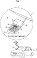
- FIG. 1 A diagram illustrating a schematic configuration of a vehicular optical system 1 according to an embodiment of the invention and an enlarged view of its main part are illustrated in FIG. 1 .
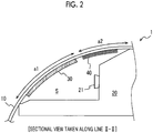
- FIG. 2 is a sectional side view taken along line II-II of the enlarged view of the main part of the vehicular optical system 1 that is illustrated in FIG. 1 .
- the vehicular optical system 1 is configured to be provided with a transparent member 10, an optical device 20, an anti-fogging portion 30, and a dew condensation portion 40.
- the transparent member 10 is, for example, a part of the glass of a windshield that transmits visible light.
- the glass of the windshield may be glass on the front side of a vehicle 2 or glass on the rear side of the vehicle 2.
- the transparent member 10 may also be a transparent acrylic plate or the like instead of the glass of the windshield.
- the vehicular optical system 1 will be described on the assumption that the transparent member 10 is a part of the windshield (hereinafter, the transparent member 10 will be referred to as a "windshield 10").
- the optical device 20 is disposed on, for example, the inner side of the windshield 10 that is in the vehicle cabin.
- the optical device 20 is provided with an optical unit 21 such as an imaging camera and/or a laser sensor.
- the imaging camera captures images around the vehicle and the laser sensor detects targets present around the vehicle.
- the optical device 20 is configured to be capable of acquiring information on the environment that is in front of the vehicle cabin of the vehicle 2 through the windshield 10.
- the information acquired by the optical device 20 is used by an in-vehicle preventive safety system (not illustrated) for collision avoidance assistance or the like.
- the optical device 20 is disposed with a predetermined closed space S formed between the windshield 10 and the optical device 20.
- the closed space S does not have to be sealed.
- the closed space S may have a gap of an extent in which the air inside the closed space S and the air outside the closed space S (inside the vehicle cabin) does not actively circulate.
- the inner surface of the windshield 10 that is in the closed space S is divided into a first region a1 and a second region a2.
- the first region a1 is the inner surface region of the windshield 10 that is within the angle of view of the optical device 20. Specifically, the first region a1 is the inner surface region of the windshield 10 that is within the angle of view of the optical unit 21 such as the imaging camera and the laser sensor.
- the first region a1 is a region that may affect the operation of the preventive safety system when the glass becomes, for example, foggy.
- the anti-fogging portion 30 capable of suppressing the fogging of the windshield 10 is disposed in the first region a1.
- the anti-fogging portion 30 may be, for example, an anti-fogging sheet as a component that has moisture absorbing properties and transmits visible light.
- the anti-fogging sheet can be attached to the first region a1 of the windshield 10 from the inner side of the vehicle cabin.
- the anti-fogging portion 30 may be disposed in the entire first region a1 or may be disposed at a part of the first region a1.
- the second region a2 is the inner surface region of the windshield 10 that is out of the angle of view of the optical device 20. Specifically, the second region a2 is the inner surface region of the windshield 10 that is out of the angle of view of the optical unit 21 such as the imaging camera and the laser sensor. The second region a2 is a region that does not affect the operation of the preventive safety system even when the glass becomes, for example, foggy.
- the dew condensation portion 40 is disposed in the second region a2. Dew condensation is more likely to occur in the dew condensation portion 40 than in the first region a1.
- the dew condensation portion 40 can be realized by, for example, the windshield 10 being formed such that the thickness of the windshield 10 is thinner in the second region a2 than in the first region a1.
- the thermal conductivity of the second region a2 is improved more than the thermal conductivity of the first region a1. Accordingly, in a situation in which the glass is likely to become foggy, dew condensation is more likely to occur in the second region a2 than in the first region a1 as the temperature of the inner surface of the glass becomes lower in the second region a2 than in the first region a1. Examples of the situation include an outside air temperature being lower than the temperature in the vehicle cabin.
- the dew condensation portion 40 can be realized by, for example, the windshield 10 being formed such that the surface area of the windshield 10 per coating area is larger in the second region a2 than in the first region a1. More specifically, the surface area of the glass per coating area is increased by unevenness being formed on the surface of the glass. When the windshield 10 is formed in this manner, the efficiency of heat exchange between the outside air and the inside air per coating area is improved more in the second region a2 than in the first region a1.
- dew condensation is more likely to occur in the second region a2 than in the first region a1 as the surface area of the glass undergoing a decline in temperature is wider in the second region a2 than in the first region a1.
- Examples of the situation include an outside air temperature being lower than the temperature in the vehicle cabin.
- the dew condensation portion 40 may be disposed in the entire second region a2 or may be disposed at a part of the second region a2. In addition, the dew condensation portion 40 may be disposed continuously from the anti-fogging portion 30 or may not be disposed continuously from the anti-fogging portion 30 as illustrated in FIG. 2 (In other words, a gap may be formed between the dew condensation portion 40 and the anti-fogging portion 30).
- the anti-fogging portion 30 is disposed in the first region a1 of the inner surface of the transparent member 10 such as the windshield and the first region a1 is within the angle of view of the optical device 20 as described above.
- the dew condensation portion 40 is disposed in the second region a2 that is out of the angle of view of the optical device 20 and dew condensation is more likely to occur in the second region a2 than in the first region a1 as described above.
- dew condensation by the dew condensation portion 40 can be preferentially performed (activation of dew condensation) before moisture absorption by the anti-fogging portion (anti-fogging sheet) 30, the moisture (water vapor) that is included in the closed space S and causes the transparent member 10 such as the windshield to become foggy is allowed to concentrate in the dew condensation portion 40, and thus the amount of the moisture in the anti-fogging portion 30 can be decreased. Accordingly, the anti-fogging portion 30 becomes unlikely to reach a moisture absorption limit and the anti-fogging properties of the first region a1 in front of the optical device 20 are improved. Therefore, the possibility of the vehicular optical system 1 not being operated properly by the inner surface (first region a1) of the transparent member 10 such as the windshield becoming foggy can be suppressed.
- the dew condensation portion 40 is realized by the shape (thickness and unevenness) of the transparent member 10 such as the windshield without any new configuration being added. Accordingly, an increase in the complexity of the structure of the system and a rise in system cost attributable to an increase in the number of components can be effectively avoided.
- the invention can be used in an optical system that is mounted in a vehicle and is useful in a case where, for example, the possibility of the system not being operated properly by a transparent member such as a windshield becoming foggy is to be suppressed with the transparent member in front of an optical device and within the angle of view of the optical device.
Landscapes
- Physics & Mathematics (AREA)
- General Physics & Mathematics (AREA)
- Engineering & Computer Science (AREA)
- Mechanical Engineering (AREA)
- Multimedia (AREA)
- Signal Processing (AREA)
- Optics & Photonics (AREA)
- Air-Conditioning For Vehicles (AREA)
- Fittings On The Vehicle Exterior For Carrying Loads, And Devices For Holding Or Mounting Articles (AREA)
- Lens Barrels (AREA)
- Window Of Vehicle (AREA)
Abstract
Description
- The invention relates to an optical system mounted in a vehicle.
- A vehicular optical system is known that acquires information on the environment in front of and behind a vehicle by using an optical device including a camera and so on and uses the information to assist in the driving of the vehicle by a driver. In most cases, the vehicular optical system is installed on the inner side of a windshield or a rear window, which is inside the vehicle cabin of the vehicle.
- The vehicular optical system described above may not be operated properly when a lens and glass in front of the optical device becomes foggy due to, for example, the difference between the temperature of the air inside the vehicle and the temperature of the air outside the vehicle. In this regard, the glass and the lens are restrained from becoming foggy by an anti-fogging portion (such as an anti-fogging sheet, an anti-fogging film, and a hydrophilic film) that has an anti-fogging performance being disposed in the glass and the lens. This type of structure is disclosed in, for example, Japanese Unexamined Patent Application Publication No.
2002-350966 JP 2002-350966 A 11-084473 JP 11-084473 A 2008-239018 JP 2008-239018 A - In the structures disclosed in
JP 2002-350966 A JP 11-084473 A JP 2008-239018 A - The invention provides a vehicular optical system that is capable of suppressing the possibility of the system not being operated properly by a transparent member becoming foggy with the transparent member in front of an optical device and within the angle of view of the optical device.
- An aspect of the invention relates to a vehicular optical system. The vehicular optical system includes an optical device, a transparent member, an anti-fogging sheet, and a dew condensation portion. The optical device is disposed to acquire information on an environment outside a vehicle cabin. The transparent member is disposed on a front surface of the optical device via a predetermined closed space. The anti-fogging sheet is disposed in a first region of an inner surface of the transparent member in the closed space, the first region being within an angle of view of the optical device. The dew condensation portion is disposed in a second region of the inner surface of the transparent member in the closed space, the second region being out of the angle of view of the optical device and dew condensation being more likely to occur in the dew condensation portion than in the first region.
- According to the aspect of the invention, dew condensation by the dew condensation portion can be preferentially performed before moisture absorption by the anti-fogging sheet, the moisture (water vapor) that is included in the closed space and causes the transparent member to become foggy is allowed to concentrate in the dew condensation portion, and thus the amount of the moisture in the anti-fogging sheet can be decreased. Accordingly, the anti-fogging sheet becomes unlikely to reach a moisture absorption limit and the anti-fogging properties of the first region (an angle of view) in front of the optical device are improved.
- In the vehicular optical system according to the aspect of the invention, the dew condensation portion may be formed by a thickness of the transparent member being thinner in the second region than in the first region.
- According to the aspect of the invention, the thermal conductivity of the transparent member can be improved more in the second region (out of the angle of view) than in the first region (angle of view) without any new configuration being added.
- In the vehicular optical system according to the aspect of the invention, the dew condensation portion may be formed by a surface area of the transparent member per coating area being larger in the second region than in the first region.
- According to the aspect of the invention, the efficiency of heat exchange of the transparent member per coating area can be improved more in the second region (out of the angle of view) than in the first region (angle of view) without any new configuration being added.
- In the vehicular optical system according to the aspect of the invention, the transparent member may be a part of a windshield.
- According to the aspect of the invention, the anti-fogging properties of the first region (angle of view) can be improved in a situation in which the temperature of the air outside the vehicle cabin of the windshield and the temperature of the air inside the vehicle cabin of the windshield differ from each other.
- With the vehicular optical system according to the aspect of the invention, the possibility of the system not being operated properly by a transparent member such as glass becoming foggy can be suppressed as described above with the glass in front of an optical device and within the angle of view of the optical device.
- Features, advantages, and technical and industrial significance of exemplary embodiments of the invention will be described below with reference to the accompanying drawings, in which like numerals denote like elements, and wherein:
-
FIG. 1 is a schematic configuration diagram of a vehicular optical system according to an embodiment of the invention and an enlarged view of its main part; and -
FIG. 2 is a sectional view taken along line II-II of the vehicular optical system illustrated inFIG. 1 . - A vehicular optical system of the invention decreases the amount of moisture in the region of the angle of view of an optical device by allowing the moisture that is included in a closed space to concentrate in a region of the inner surface of a transparent member that is out of the angle of view of the optical device with the closed space formed by the optical device and the transparent member such as a windshield being attached to each other. As a result, the possibility of the system becoming inoperable by the transparent member on the front surface of the optical device becoming foggy can be suppressed.
- A diagram illustrating a schematic configuration of a vehicular optical system 1 according to an embodiment of the invention and an enlarged view of its main part are illustrated in
FIG. 1 .FIG. 2 is a sectional side view taken along line II-II of the enlarged view of the main part of the vehicular optical system 1 that is illustrated inFIG. 1 . - As illustrated in
FIGS. 1 and2 , the vehicular optical system 1 according to the present embodiment is configured to be provided with atransparent member 10, anoptical device 20, ananti-fogging portion 30, and adew condensation portion 40. - The
transparent member 10 is, for example, a part of the glass of a windshield that transmits visible light. The glass of the windshield may be glass on the front side of a vehicle 2 or glass on the rear side of the vehicle 2. Thetransparent member 10 may also be a transparent acrylic plate or the like instead of the glass of the windshield. In the following embodiment, the vehicular optical system 1 will be described on the assumption that thetransparent member 10 is a part of the windshield (hereinafter, thetransparent member 10 will be referred to as a "windshield 10"). - The
optical device 20 is disposed on, for example, the inner side of thewindshield 10 that is in the vehicle cabin. Theoptical device 20 is provided with anoptical unit 21 such as an imaging camera and/or a laser sensor. The imaging camera captures images around the vehicle and the laser sensor detects targets present around the vehicle. Theoptical device 20 is configured to be capable of acquiring information on the environment that is in front of the vehicle cabin of the vehicle 2 through thewindshield 10. The information acquired by theoptical device 20 is used by an in-vehicle preventive safety system (not illustrated) for collision avoidance assistance or the like. - As illustrated in
FIG. 2 , theoptical device 20 is disposed with a predetermined closed space S formed between thewindshield 10 and theoptical device 20. The closed space S does not have to be sealed. For example, the closed space S may have a gap of an extent in which the air inside the closed space S and the air outside the closed space S (inside the vehicle cabin) does not actively circulate. The inner surface of thewindshield 10 that is in the closed space S is divided into a first region a1 and a second region a2. - The first region a1 is the inner surface region of the
windshield 10 that is within the angle of view of theoptical device 20. Specifically, the first region a1 is the inner surface region of thewindshield 10 that is within the angle of view of theoptical unit 21 such as the imaging camera and the laser sensor. The first region a1 is a region that may affect the operation of the preventive safety system when the glass becomes, for example, foggy. In this regard, theanti-fogging portion 30 capable of suppressing the fogging of thewindshield 10 is disposed in the first region a1. - The
anti-fogging portion 30 may be, for example, an anti-fogging sheet as a component that has moisture absorbing properties and transmits visible light. The anti-fogging sheet can be attached to the first region a1 of thewindshield 10 from the inner side of the vehicle cabin. Theanti-fogging portion 30 may be disposed in the entire first region a1 or may be disposed at a part of the first region a1. - The second region a2 is the inner surface region of the
windshield 10 that is out of the angle of view of theoptical device 20. Specifically, the second region a2 is the inner surface region of thewindshield 10 that is out of the angle of view of theoptical unit 21 such as the imaging camera and the laser sensor. The second region a2 is a region that does not affect the operation of the preventive safety system even when the glass becomes, for example, foggy. Thedew condensation portion 40 is disposed in the second region a2. Dew condensation is more likely to occur in thedew condensation portion 40 than in the first region a1. - The
dew condensation portion 40 can be realized by, for example, thewindshield 10 being formed such that the thickness of thewindshield 10 is thinner in the second region a2 than in the first region a1. By the thicknesses being given to thewindshield 10, the thermal conductivity of the second region a2 is improved more than the thermal conductivity of the first region a1. Accordingly, in a situation in which the glass is likely to become foggy, dew condensation is more likely to occur in the second region a2 than in the first region a1 as the temperature of the inner surface of the glass becomes lower in the second region a2 than in the first region a1. Examples of the situation include an outside air temperature being lower than the temperature in the vehicle cabin. - Alternatively, the
dew condensation portion 40 can be realized by, for example, thewindshield 10 being formed such that the surface area of thewindshield 10 per coating area is larger in the second region a2 than in the first region a1. More specifically, the surface area of the glass per coating area is increased by unevenness being formed on the surface of the glass. When thewindshield 10 is formed in this manner, the efficiency of heat exchange between the outside air and the inside air per coating area is improved more in the second region a2 than in the first region a1. Accordingly, in a situation in which the glass is likely to become foggy, dew condensation is more likely to occur in the second region a2 than in the first region a1 as the surface area of the glass undergoing a decline in temperature is wider in the second region a2 than in the first region a1. Examples of the situation include an outside air temperature being lower than the temperature in the vehicle cabin. - The
dew condensation portion 40 may be disposed in the entire second region a2 or may be disposed at a part of the second region a2. In addition, thedew condensation portion 40 may be disposed continuously from theanti-fogging portion 30 or may not be disposed continuously from theanti-fogging portion 30 as illustrated inFIG. 2 (In other words, a gap may be formed between thedew condensation portion 40 and the anti-fogging portion 30). - In the vehicular optical system 1 according to the embodiment of the invention, the
anti-fogging portion 30 is disposed in the first region a1 of the inner surface of thetransparent member 10 such as the windshield and the first region a1 is within the angle of view of theoptical device 20 as described above. In addition, thedew condensation portion 40 is disposed in the second region a2 that is out of the angle of view of theoptical device 20 and dew condensation is more likely to occur in the second region a2 than in the first region a1 as described above. - By this configuration being adopted, dew condensation by the
dew condensation portion 40 can be preferentially performed (activation of dew condensation) before moisture absorption by the anti-fogging portion (anti-fogging sheet) 30, the moisture (water vapor) that is included in the closed space S and causes thetransparent member 10 such as the windshield to become foggy is allowed to concentrate in thedew condensation portion 40, and thus the amount of the moisture in theanti-fogging portion 30 can be decreased. Accordingly, theanti-fogging portion 30 becomes unlikely to reach a moisture absorption limit and the anti-fogging properties of the first region a1 in front of theoptical device 20 are improved. Therefore, the possibility of the vehicular optical system 1 not being operated properly by the inner surface (first region a1) of thetransparent member 10 such as the windshield becoming foggy can be suppressed. - In the vehicular optical system 1 according to the present embodiment, the
dew condensation portion 40 is realized by the shape (thickness and unevenness) of thetransparent member 10 such as the windshield without any new configuration being added. Accordingly, an increase in the complexity of the structure of the system and a rise in system cost attributable to an increase in the number of components can be effectively avoided. - Although the invention has been described in detail above, the above description is merely an example of the invention in every respect and the scope of the invention is not limited by the above description. It is a matter of course that the invention can be improved and modified in various ways within the scope of the invention.
- The invention can be used in an optical system that is mounted in a vehicle and is useful in a case where, for example, the possibility of the system not being operated properly by a transparent member such as a windshield becoming foggy is to be suppressed with the transparent member in front of an optical device and within the angle of view of the optical device.
Claims (4)
- A vehicular optical system (1) comprising:an optical device (20) disposed to acquire information on an environment outside a vehicle cabin;a transparent member (10) disposed on a front surface of the optical device (20) via a predetermined closed space (S);an anti-fogging sheet (30) disposed in a first region (a1) of an inner surface of the transparent member (10) in the closed space (S), the first region (a1) being within an angle of view of the optical device (20); anda dew condensation portion (40) disposed in a second region (a2) of the inner surface of the transparent member (10) in the closed space (S), the second region (a2) being out of the angle of view of the optical device (20) and dew condensation being more likely to occur in the dew condensation portion (40) than in the first region (a1).
- The vehicular optical system according to claim 1, wherein the dew condensation portion (40) is formed by a thickness of the transparent member (10) being thinner in the second region (a2) than in the first region (a1).
- The vehicular optical system according to claim 1, wherein the dew condensation portion (40) is formed by a surface area of the transparent member (10) per coating area being larger in the second region (a2) than in the first region (a1).
- The vehicular optical system according to claim 1, wherein the transparent member (10) is a part of a windshield.
Applications Claiming Priority (1)
| Application Number | Priority Date | Filing Date | Title |
|---|---|---|---|
| JP2017014492A JP6593360B2 (en) | 2017-01-30 | 2017-01-30 | Vehicle optical system |
Publications (2)
| Publication Number | Publication Date |
|---|---|
| EP3354518A1 true EP3354518A1 (en) | 2018-08-01 |
| EP3354518B1 EP3354518B1 (en) | 2021-02-24 |
Family
ID=61132042
Family Applications (1)
| Application Number | Title | Priority Date | Filing Date |
|---|---|---|---|
| EP18154199.6A Active EP3354518B1 (en) | 2017-01-30 | 2018-01-30 | Anti-fogging device for vehicular optical system |
Country Status (6)
| Country | Link |
|---|---|
| US (1) | US10513168B2 (en) |
| EP (1) | EP3354518B1 (en) |
| JP (1) | JP6593360B2 (en) |
| CN (1) | CN108437895B (en) |
| CA (1) | CA2993379C (en) |
| RU (1) | RU2673790C1 (en) |
Families Citing this family (6)
| Publication number | Priority date | Publication date | Assignee | Title |
|---|---|---|---|---|
| JP6988883B2 (en) * | 2017-03-21 | 2022-01-05 | Agc株式会社 | Vehicle front windows and vehicle goods |
| WO2019205149A1 (en) * | 2018-04-28 | 2019-10-31 | 深圳市大疆创新科技有限公司 | Distance detection apparatus |
| JP6999537B2 (en) * | 2018-12-20 | 2022-01-18 | イーソル株式会社 | Portable input terminal |
| CN110077333A (en) * | 2019-04-18 | 2019-08-02 | 上海赫千电子科技有限公司 | A kind of adjustable camera |
| CN113829995A (en) * | 2020-06-22 | 2021-12-24 | 吉林省瑞中科技有限公司 | Auxiliary driving information projection system |
| JP7575302B2 (en) * | 2021-03-09 | 2024-10-29 | 本田技研工業株式会社 | Body structure having a camera |
Citations (8)
| Publication number | Priority date | Publication date | Assignee | Title |
|---|---|---|---|---|
| JPH1184473A (en) | 1997-09-05 | 1999-03-26 | Canon Inc | Observation optical system and optical apparatus having the same |
| JP2002350966A (en) | 2001-05-25 | 2002-12-04 | Hitachi Building Systems Co Ltd | surveillance camera |
| EP1405718A1 (en) * | 2001-06-11 | 2004-04-07 | Murakami Corporation | Antifogging element and method for forming the same |
| WO2006112529A1 (en) * | 2005-04-18 | 2006-10-26 | Asahi Glass Company, Limited | Windshield with antifogging layer and automobile employing said windshield |
| JP2008239018A (en) | 2007-03-28 | 2008-10-09 | Clarion Co Ltd | On-vehicle camera |
| WO2015115399A1 (en) * | 2014-01-28 | 2015-08-06 | 太陽化学工業株式会社 | Structure provided with carbon film and method for forming carbon film |
| JP2015169816A (en) * | 2014-03-07 | 2015-09-28 | 船井電機株式会社 | Condensation prevention structure for optical component and head-up display device |
| WO2016129699A1 (en) * | 2015-02-13 | 2016-08-18 | 日本板硝子株式会社 | Windshield |
Family Cites Families (18)
| Publication number | Priority date | Publication date | Assignee | Title |
|---|---|---|---|---|
| SU1670547A1 (en) * | 1989-01-02 | 1991-08-15 | Научно-Производственное Объединение По Автоэлектронике И Автотракторному Электрооборудованию | Automobile rear view mirror |
| US5877897A (en) * | 1993-02-26 | 1999-03-02 | Donnelly Corporation | Automatic rearview mirror, vehicle lighting control and vehicle interior monitoring system using a photosensor array |
| JPH0719701U (en) * | 1993-09-13 | 1995-04-07 | 東京メガネ製造株式会社 | Anti-fog seal |
| DE10237608A1 (en) * | 2002-08-16 | 2004-02-26 | Hella Kg Hueck & Co. | Camera arrangement for motor vehicles |
| AU2003290791A1 (en) * | 2002-11-14 | 2004-06-15 | Donnelly Corporation | Imaging system for vehicle |
| JP2004276857A (en) | 2003-03-18 | 2004-10-07 | Denso Corp | Vehicle window glass anti-fog equipment |
| DE102004057322B4 (en) * | 2004-11-27 | 2021-01-28 | Volkswagen Ag | Arrangement of a camera behind vehicle glazing and a motor vehicle |
| KR100620966B1 (en) * | 2004-12-15 | 2006-09-19 | 삼성전자주식회사 | Screen adaptive power control device and method |
| CN100595608C (en) * | 2005-02-18 | 2010-03-24 | 佳能株式会社 | Optically transparent component and optical system using the optically transparent component |
| JP2008233547A (en) * | 2007-03-20 | 2008-10-02 | Hoya Corp | Lens glass material for on-vehicle camera and lens for on-vehicle camera |
| US8194028B2 (en) * | 2008-02-29 | 2012-06-05 | Research In Motion Limited | System and method for adjusting an intensity value and a backlight level for a display of an electronic device |
| DE102009026319A1 (en) * | 2009-08-04 | 2011-02-24 | Saint-Gobain Sekurit Deutschland Gmbh & Co. Kg | Disc with optically transparent sensor field |
| US8398234B2 (en) * | 2011-05-03 | 2013-03-19 | Kimberly-Clark Worldwide, Inc. | Electro-thermal antifog optical devices |
| JP6214281B2 (en) * | 2013-08-30 | 2017-10-18 | クラリオン株式会社 | In-vehicle camera |
| US9395538B2 (en) * | 2014-09-26 | 2016-07-19 | Delphi Technologies, Inc. | Vehicle imager assembly with localized window defogging |
| US10660533B2 (en) * | 2014-09-30 | 2020-05-26 | Rapsodo Pte. Ltd. | Remote heart rate monitoring based on imaging for moving subjects |
| JP6440095B2 (en) | 2015-04-15 | 2018-12-19 | コニカミノルタ株式会社 | Optical scanning type object detection device |
| CN204669633U (en) * | 2015-06-23 | 2015-09-23 | 北京美好生活家居用品有限公司 | A kind of automobile rearview mirror heating plate |
-
2017
- 2017-01-30 JP JP2017014492A patent/JP6593360B2/en active Active
-
2018
- 2018-01-26 US US15/881,096 patent/US10513168B2/en active Active
- 2018-01-29 CN CN201810082974.7A patent/CN108437895B/en active Active
- 2018-01-29 RU RU2018103153A patent/RU2673790C1/en active
- 2018-01-30 EP EP18154199.6A patent/EP3354518B1/en active Active
- 2018-01-30 CA CA2993379A patent/CA2993379C/en active Active
Patent Citations (8)
| Publication number | Priority date | Publication date | Assignee | Title |
|---|---|---|---|---|
| JPH1184473A (en) | 1997-09-05 | 1999-03-26 | Canon Inc | Observation optical system and optical apparatus having the same |
| JP2002350966A (en) | 2001-05-25 | 2002-12-04 | Hitachi Building Systems Co Ltd | surveillance camera |
| EP1405718A1 (en) * | 2001-06-11 | 2004-04-07 | Murakami Corporation | Antifogging element and method for forming the same |
| WO2006112529A1 (en) * | 2005-04-18 | 2006-10-26 | Asahi Glass Company, Limited | Windshield with antifogging layer and automobile employing said windshield |
| JP2008239018A (en) | 2007-03-28 | 2008-10-09 | Clarion Co Ltd | On-vehicle camera |
| WO2015115399A1 (en) * | 2014-01-28 | 2015-08-06 | 太陽化学工業株式会社 | Structure provided with carbon film and method for forming carbon film |
| JP2015169816A (en) * | 2014-03-07 | 2015-09-28 | 船井電機株式会社 | Condensation prevention structure for optical component and head-up display device |
| WO2016129699A1 (en) * | 2015-02-13 | 2016-08-18 | 日本板硝子株式会社 | Windshield |
Also Published As
| Publication number | Publication date |
|---|---|
| CN108437895B (en) | 2021-04-02 |
| US20180215239A1 (en) | 2018-08-02 |
| EP3354518B1 (en) | 2021-02-24 |
| CA2993379C (en) | 2019-02-26 |
| US10513168B2 (en) | 2019-12-24 |
| CA2993379A1 (en) | 2018-07-30 |
| JP6593360B2 (en) | 2019-10-23 |
| CN108437895A (en) | 2018-08-24 |
| JP2018122634A (en) | 2018-08-09 |
| RU2673790C1 (en) | 2018-11-29 |
Similar Documents
| Publication | Publication Date | Title |
|---|---|---|
| EP3354518B1 (en) | Anti-fogging device for vehicular optical system | |
| CN108696676B (en) | camera module | |
| EP3054348B1 (en) | Stereo camera for a vehicle | |
| JP6573713B2 (en) | In-vehicle image processing device | |
| JP6419822B2 (en) | Camera module for automobile and method for attaching camera module | |
| JP2017515734A (en) | Vehicle assistant system | |
| CN107031568A (en) | vehicle-mounted shooting device | |
| CN111344190B (en) | Vehicle driver assistance system | |
| JP6642172B2 (en) | Head-up display device | |
| JP2015107764A (en) | Camera mounting structure | |
| US11772575B2 (en) | In-vehicle camera device and vehicle | |
| EP3457194A1 (en) | Head-up display device | |
| JP4045871B2 (en) | Camera cover for on-board camera | |
| JP4754284B2 (en) | Thermal insulation structure for in-vehicle equipment | |
| EP3034359B1 (en) | Monitoring system, and vehicle mountable with monitoring system | |
| JP2016113142A (en) | Camera for movable body, and movable body equipped with the same | |
| WO2022207140A1 (en) | An imaging device for a driver monitoring system | |
| US9079538B2 (en) | Pair of external vehicle mirrors | |
| JP2024066108A (en) | Imaging device | |
| JP2023067565A (en) | Vehicle periphery detection device mounting bracket and vehicle periphery detection device mounting structure | |
| JP2006240404A (en) | In-vehicle camera photographing device | |
| JP2019211492A (en) | Display device | |
| JP2007290486A (en) | Night information provider |
Legal Events
| Date | Code | Title | Description |
|---|---|---|---|
| PUAI | Public reference made under article 153(3) epc to a published international application that has entered the european phase |
Free format text: ORIGINAL CODE: 0009012 |
|
| STAA | Information on the status of an ep patent application or granted ep patent |
Free format text: STATUS: REQUEST FOR EXAMINATION WAS MADE |
|
| 17P | Request for examination filed |
Effective date: 20180130 |
|
| AK | Designated contracting states |
Kind code of ref document: A1 Designated state(s): AL AT BE BG CH CY CZ DE DK EE ES FI FR GB GR HR HU IE IS IT LI LT LU LV MC MK MT NL NO PL PT RO RS SE SI SK SM TR |
|
| AX | Request for extension of the european patent |
Extension state: BA ME |
|
| STAA | Information on the status of an ep patent application or granted ep patent |
Free format text: STATUS: EXAMINATION IS IN PROGRESS |
|
| 17Q | First examination report despatched |
Effective date: 20190611 |
|
| REG | Reference to a national code |
Ref country code: DE Ref legal event code: R079 Ref document number: 602018012838 Country of ref document: DE Free format text: PREVIOUS MAIN CLASS: B60R0001040000 Ipc: G03B0017020000 |
|
| RIC1 | Information provided on ipc code assigned before grant |
Ipc: B60S 1/02 20060101ALI20200803BHEP Ipc: G03B 17/08 20060101ALI20200803BHEP Ipc: G03B 29/00 20060101ALI20200803BHEP Ipc: B60R 11/04 20060101ALI20200803BHEP Ipc: B60R 11/00 20060101ALI20200803BHEP Ipc: G03B 17/02 20060101AFI20200803BHEP Ipc: G03B 17/56 20060101ALI20200803BHEP |
|
| GRAP | Despatch of communication of intention to grant a patent |
Free format text: ORIGINAL CODE: EPIDOSNIGR1 |
|
| STAA | Information on the status of an ep patent application or granted ep patent |
Free format text: STATUS: GRANT OF PATENT IS INTENDED |
|
| INTG | Intention to grant announced |
Effective date: 20201008 |
|
| GRAS | Grant fee paid |
Free format text: ORIGINAL CODE: EPIDOSNIGR3 |
|
| GRAA | (expected) grant |
Free format text: ORIGINAL CODE: 0009210 |
|
| STAA | Information on the status of an ep patent application or granted ep patent |
Free format text: STATUS: THE PATENT HAS BEEN GRANTED |
|
| AK | Designated contracting states |
Kind code of ref document: B1 Designated state(s): AL AT BE BG CH CY CZ DE DK EE ES FI FR GB GR HR HU IE IS IT LI LT LU LV MC MK MT NL NO PL PT RO RS SE SI SK SM TR |
|
| REG | Reference to a national code |
Ref country code: CH Ref legal event code: EP |
|
| REG | Reference to a national code |
Ref country code: DE Ref legal event code: R096 Ref document number: 602018012838 Country of ref document: DE |
|
| REG | Reference to a national code |
Ref country code: AT Ref legal event code: REF Ref document number: 1365240 Country of ref document: AT Kind code of ref document: T Effective date: 20210315 |
|
| REG | Reference to a national code |
Ref country code: IE Ref legal event code: FG4D |
|
| REG | Reference to a national code |
Ref country code: LT Ref legal event code: MG9D |
|
| REG | Reference to a national code |
Ref country code: NL Ref legal event code: MP Effective date: 20210224 |
|
| PG25 | Lapsed in a contracting state [announced via postgrant information from national office to epo] |
Ref country code: LT Free format text: LAPSE BECAUSE OF FAILURE TO SUBMIT A TRANSLATION OF THE DESCRIPTION OR TO PAY THE FEE WITHIN THE PRESCRIBED TIME-LIMIT Effective date: 20210224 Ref country code: BG Free format text: LAPSE BECAUSE OF FAILURE TO SUBMIT A TRANSLATION OF THE DESCRIPTION OR TO PAY THE FEE WITHIN THE PRESCRIBED TIME-LIMIT Effective date: 20210524 Ref country code: PT Free format text: LAPSE BECAUSE OF FAILURE TO SUBMIT A TRANSLATION OF THE DESCRIPTION OR TO PAY THE FEE WITHIN THE PRESCRIBED TIME-LIMIT Effective date: 20210624 Ref country code: NO Free format text: LAPSE BECAUSE OF FAILURE TO SUBMIT A TRANSLATION OF THE DESCRIPTION OR TO PAY THE FEE WITHIN THE PRESCRIBED TIME-LIMIT Effective date: 20210524 Ref country code: FI Free format text: LAPSE BECAUSE OF FAILURE TO SUBMIT A TRANSLATION OF THE DESCRIPTION OR TO PAY THE FEE WITHIN THE PRESCRIBED TIME-LIMIT Effective date: 20210224 Ref country code: HR Free format text: LAPSE BECAUSE OF FAILURE TO SUBMIT A TRANSLATION OF THE DESCRIPTION OR TO PAY THE FEE WITHIN THE PRESCRIBED TIME-LIMIT Effective date: 20210224 Ref country code: GR Free format text: LAPSE BECAUSE OF FAILURE TO SUBMIT A TRANSLATION OF THE DESCRIPTION OR TO PAY THE FEE WITHIN THE PRESCRIBED TIME-LIMIT Effective date: 20210525 |
|
| REG | Reference to a national code |
Ref country code: AT Ref legal event code: MK05 Ref document number: 1365240 Country of ref document: AT Kind code of ref document: T Effective date: 20210224 |
|
| PG25 | Lapsed in a contracting state [announced via postgrant information from national office to epo] |
Ref country code: SE Free format text: LAPSE BECAUSE OF FAILURE TO SUBMIT A TRANSLATION OF THE DESCRIPTION OR TO PAY THE FEE WITHIN THE PRESCRIBED TIME-LIMIT Effective date: 20210224 Ref country code: RS Free format text: LAPSE BECAUSE OF FAILURE TO SUBMIT A TRANSLATION OF THE DESCRIPTION OR TO PAY THE FEE WITHIN THE PRESCRIBED TIME-LIMIT Effective date: 20210224 Ref country code: PL Free format text: LAPSE BECAUSE OF FAILURE TO SUBMIT A TRANSLATION OF THE DESCRIPTION OR TO PAY THE FEE WITHIN THE PRESCRIBED TIME-LIMIT Effective date: 20210224 Ref country code: NL Free format text: LAPSE BECAUSE OF FAILURE TO SUBMIT A TRANSLATION OF THE DESCRIPTION OR TO PAY THE FEE WITHIN THE PRESCRIBED TIME-LIMIT Effective date: 20210224 Ref country code: LV Free format text: LAPSE BECAUSE OF FAILURE TO SUBMIT A TRANSLATION OF THE DESCRIPTION OR TO PAY THE FEE WITHIN THE PRESCRIBED TIME-LIMIT Effective date: 20210224 |
|
| PG25 | Lapsed in a contracting state [announced via postgrant information from national office to epo] |
Ref country code: IS Free format text: LAPSE BECAUSE OF FAILURE TO SUBMIT A TRANSLATION OF THE DESCRIPTION OR TO PAY THE FEE WITHIN THE PRESCRIBED TIME-LIMIT Effective date: 20210624 |
|
| PG25 | Lapsed in a contracting state [announced via postgrant information from national office to epo] |
Ref country code: EE Free format text: LAPSE BECAUSE OF FAILURE TO SUBMIT A TRANSLATION OF THE DESCRIPTION OR TO PAY THE FEE WITHIN THE PRESCRIBED TIME-LIMIT Effective date: 20210224 Ref country code: CZ Free format text: LAPSE BECAUSE OF FAILURE TO SUBMIT A TRANSLATION OF THE DESCRIPTION OR TO PAY THE FEE WITHIN THE PRESCRIBED TIME-LIMIT Effective date: 20210224 Ref country code: SM Free format text: LAPSE BECAUSE OF FAILURE TO SUBMIT A TRANSLATION OF THE DESCRIPTION OR TO PAY THE FEE WITHIN THE PRESCRIBED TIME-LIMIT Effective date: 20210224 Ref country code: AT Free format text: LAPSE BECAUSE OF FAILURE TO SUBMIT A TRANSLATION OF THE DESCRIPTION OR TO PAY THE FEE WITHIN THE PRESCRIBED TIME-LIMIT Effective date: 20210224 |
|
| REG | Reference to a national code |
Ref country code: DE Ref legal event code: R097 Ref document number: 602018012838 Country of ref document: DE |
|
| PG25 | Lapsed in a contracting state [announced via postgrant information from national office to epo] |
Ref country code: RO Free format text: LAPSE BECAUSE OF FAILURE TO SUBMIT A TRANSLATION OF THE DESCRIPTION OR TO PAY THE FEE WITHIN THE PRESCRIBED TIME-LIMIT Effective date: 20210224 Ref country code: SK Free format text: LAPSE BECAUSE OF FAILURE TO SUBMIT A TRANSLATION OF THE DESCRIPTION OR TO PAY THE FEE WITHIN THE PRESCRIBED TIME-LIMIT Effective date: 20210224 Ref country code: DK Free format text: LAPSE BECAUSE OF FAILURE TO SUBMIT A TRANSLATION OF THE DESCRIPTION OR TO PAY THE FEE WITHIN THE PRESCRIBED TIME-LIMIT Effective date: 20210224 |
|
| PLBE | No opposition filed within time limit |
Free format text: ORIGINAL CODE: 0009261 |
|
| STAA | Information on the status of an ep patent application or granted ep patent |
Free format text: STATUS: NO OPPOSITION FILED WITHIN TIME LIMIT |
|
| PG25 | Lapsed in a contracting state [announced via postgrant information from national office to epo] |
Ref country code: AL Free format text: LAPSE BECAUSE OF FAILURE TO SUBMIT A TRANSLATION OF THE DESCRIPTION OR TO PAY THE FEE WITHIN THE PRESCRIBED TIME-LIMIT Effective date: 20210224 Ref country code: ES Free format text: LAPSE BECAUSE OF FAILURE TO SUBMIT A TRANSLATION OF THE DESCRIPTION OR TO PAY THE FEE WITHIN THE PRESCRIBED TIME-LIMIT Effective date: 20210224 |
|
| 26N | No opposition filed |
Effective date: 20211125 |
|
| PG25 | Lapsed in a contracting state [announced via postgrant information from national office to epo] |
Ref country code: SI Free format text: LAPSE BECAUSE OF FAILURE TO SUBMIT A TRANSLATION OF THE DESCRIPTION OR TO PAY THE FEE WITHIN THE PRESCRIBED TIME-LIMIT Effective date: 20210224 |
|
| PG25 | Lapsed in a contracting state [announced via postgrant information from national office to epo] |
Ref country code: IT Free format text: LAPSE BECAUSE OF FAILURE TO SUBMIT A TRANSLATION OF THE DESCRIPTION OR TO PAY THE FEE WITHIN THE PRESCRIBED TIME-LIMIT Effective date: 20210224 |
|
| PG25 | Lapsed in a contracting state [announced via postgrant information from national office to epo] |
Ref country code: IS Free format text: LAPSE BECAUSE OF FAILURE TO SUBMIT A TRANSLATION OF THE DESCRIPTION OR TO PAY THE FEE WITHIN THE PRESCRIBED TIME-LIMIT Effective date: 20210624 |
|
| PG25 | Lapsed in a contracting state [announced via postgrant information from national office to epo] |
Ref country code: MC Free format text: LAPSE BECAUSE OF FAILURE TO SUBMIT A TRANSLATION OF THE DESCRIPTION OR TO PAY THE FEE WITHIN THE PRESCRIBED TIME-LIMIT Effective date: 20210224 |
|
| REG | Reference to a national code |
Ref country code: CH Ref legal event code: PL |
|
| REG | Reference to a national code |
Ref country code: BE Ref legal event code: MM Effective date: 20220131 |
|
| PG25 | Lapsed in a contracting state [announced via postgrant information from national office to epo] |
Ref country code: LU Free format text: LAPSE BECAUSE OF NON-PAYMENT OF DUE FEES Effective date: 20220130 |
|
| PG25 | Lapsed in a contracting state [announced via postgrant information from national office to epo] |
Ref country code: BE Free format text: LAPSE BECAUSE OF NON-PAYMENT OF DUE FEES Effective date: 20220131 |
|
| PG25 | Lapsed in a contracting state [announced via postgrant information from national office to epo] |
Ref country code: LI Free format text: LAPSE BECAUSE OF NON-PAYMENT OF DUE FEES Effective date: 20220131 Ref country code: CH Free format text: LAPSE BECAUSE OF NON-PAYMENT OF DUE FEES Effective date: 20220131 |
|
| PG25 | Lapsed in a contracting state [announced via postgrant information from national office to epo] |
Ref country code: IE Free format text: LAPSE BECAUSE OF NON-PAYMENT OF DUE FEES Effective date: 20220130 |
|
| P01 | Opt-out of the competence of the unified patent court (upc) registered |
Effective date: 20230427 |
|
| REG | Reference to a national code |
Ref country code: DE Ref legal event code: R084 Ref document number: 602018012838 Country of ref document: DE |
|
| REG | Reference to a national code |
Ref country code: GB Ref legal event code: 746 Effective date: 20230816 |
|
| PG25 | Lapsed in a contracting state [announced via postgrant information from national office to epo] |
Ref country code: HU Free format text: LAPSE BECAUSE OF FAILURE TO SUBMIT A TRANSLATION OF THE DESCRIPTION OR TO PAY THE FEE WITHIN THE PRESCRIBED TIME-LIMIT; INVALID AB INITIO Effective date: 20180130 |
|
| PG25 | Lapsed in a contracting state [announced via postgrant information from national office to epo] |
Ref country code: MK Free format text: LAPSE BECAUSE OF FAILURE TO SUBMIT A TRANSLATION OF THE DESCRIPTION OR TO PAY THE FEE WITHIN THE PRESCRIBED TIME-LIMIT Effective date: 20210224 Ref country code: CY Free format text: LAPSE BECAUSE OF FAILURE TO SUBMIT A TRANSLATION OF THE DESCRIPTION OR TO PAY THE FEE WITHIN THE PRESCRIBED TIME-LIMIT Effective date: 20210224 |
|
| PG25 | Lapsed in a contracting state [announced via postgrant information from national office to epo] |
Ref country code: TR Free format text: LAPSE BECAUSE OF FAILURE TO SUBMIT A TRANSLATION OF THE DESCRIPTION OR TO PAY THE FEE WITHIN THE PRESCRIBED TIME-LIMIT Effective date: 20210224 |
|
| PG25 | Lapsed in a contracting state [announced via postgrant information from national office to epo] |
Ref country code: MT Free format text: LAPSE BECAUSE OF FAILURE TO SUBMIT A TRANSLATION OF THE DESCRIPTION OR TO PAY THE FEE WITHIN THE PRESCRIBED TIME-LIMIT Effective date: 20210224 |
|
| PGFP | Annual fee paid to national office [announced via postgrant information from national office to epo] |
Ref country code: GB Payment date: 20251211 Year of fee payment: 9 |
|
| PGFP | Annual fee paid to national office [announced via postgrant information from national office to epo] |
Ref country code: FR Payment date: 20251128 Year of fee payment: 9 |
|
| PGFP | Annual fee paid to national office [announced via postgrant information from national office to epo] |
Ref country code: DE Payment date: 20251203 Year of fee payment: 9 |