EP3353939B1 - Ressourcenpoolauswahl per paket in einem lte-v2x system - Google Patents
Ressourcenpoolauswahl per paket in einem lte-v2x system Download PDFInfo
- Publication number
- EP3353939B1 EP3353939B1 EP16774549.6A EP16774549A EP3353939B1 EP 3353939 B1 EP3353939 B1 EP 3353939B1 EP 16774549 A EP16774549 A EP 16774549A EP 3353939 B1 EP3353939 B1 EP 3353939B1
- Authority
- EP
- European Patent Office
- Prior art keywords
- data packet
- node
- tag
- mapping
- logical channel
- Prior art date
- Legal status (The legal status is an assumption and is not a legal conclusion. Google has not performed a legal analysis and makes no representation as to the accuracy of the status listed.)
- Active
Links
Images




Classifications
-
- H—ELECTRICITY
- H04—ELECTRIC COMMUNICATION TECHNIQUE
- H04W—WIRELESS COMMUNICATION NETWORKS
- H04W72/00—Local resource management
- H04W72/50—Allocation or scheduling criteria for wireless resources
- H04W72/54—Allocation or scheduling criteria for wireless resources based on quality criteria
-
- H—ELECTRICITY
- H04—ELECTRIC COMMUNICATION TECHNIQUE
- H04L—TRANSMISSION OF DIGITAL INFORMATION, e.g. TELEGRAPHIC COMMUNICATION
- H04L5/00—Arrangements affording multiple use of the transmission path
- H04L5/003—Arrangements for allocating sub-channels of the transmission path
- H04L5/0044—Allocation of payload; Allocation of data channels, e.g. PDSCH or PUSCH
-
- H—ELECTRICITY
- H04—ELECTRIC COMMUNICATION TECHNIQUE
- H04L—TRANSMISSION OF DIGITAL INFORMATION, e.g. TELEGRAPHIC COMMUNICATION
- H04L5/00—Arrangements affording multiple use of the transmission path
- H04L5/003—Arrangements for allocating sub-channels of the transmission path
- H04L5/0058—Allocation criteria
-
- H—ELECTRICITY
- H04—ELECTRIC COMMUNICATION TECHNIQUE
- H04W—WIRELESS COMMUNICATION NETWORKS
- H04W4/00—Services specially adapted for wireless communication networks; Facilities therefor
- H04W4/30—Services specially adapted for particular environments, situations or purposes
- H04W4/40—Services specially adapted for particular environments, situations or purposes for vehicles, e.g. vehicle-to-pedestrians [V2P]
-
- H—ELECTRICITY
- H04—ELECTRIC COMMUNICATION TECHNIQUE
- H04W—WIRELESS COMMUNICATION NETWORKS
- H04W72/00—Local resource management
- H04W72/12—Wireless traffic scheduling
-
- H—ELECTRICITY
- H04—ELECTRIC COMMUNICATION TECHNIQUE
- H04W—WIRELESS COMMUNICATION NETWORKS
- H04W80/00—Wireless network protocols or protocol adaptations to wireless operation
- H04W80/02—Data link layer protocols
-
- H—ELECTRICITY
- H04—ELECTRIC COMMUNICATION TECHNIQUE
- H04W—WIRELESS COMMUNICATION NETWORKS
- H04W80/00—Wireless network protocols or protocol adaptations to wireless operation
- H04W80/08—Upper layer protocols
- H04W80/12—Application layer protocols, e.g. WAP [Wireless Application Protocol]
-
- H—ELECTRICITY
- H04—ELECTRIC COMMUNICATION TECHNIQUE
- H04W—WIRELESS COMMUNICATION NETWORKS
- H04W84/00—Network topologies
- H04W84/02—Hierarchically pre-organised networks, e.g. paging networks, cellular networks, WLAN [Wireless Local Area Network] or WLL [Wireless Local Loop]
- H04W84/04—Large scale networks; Deep hierarchical networks
Definitions
- the present disclosure relates, in general, to wireless communications and, more particularly, per-packet resource pool selection in LTE V2X systems.
- LTE Long Term Evolution
- D2D device-to-device
- ProSe Proximity Services
- An example application enabled by Release 12 LTE is device discovery, where devices are able to sense the proximity of another device and associated application by broadcasting and detecting discovery messages that carry device and application identities.
- Another example application is direct communication based on physical channels terminated directly between devices.
- V2X communication includes any combination of direct communication between vehicles, pedestrians and infrastructure.
- V2X communication may take advantage of a network infrastructure, when available, but at least basic V2X connectivity should be possible even in case of lack of coverage.
- Providing an LTE-based V2X interface may be economically advantageous because of the LTE economies of scale, and it may enable tighter integration between communications with the network infrastructure (V2I/V2N), vehicle-to-pedestrian (V2P) communications, and vehicle-to-vehicle (V2V) communications, as compared to using a dedicated V2X technology.
- V2X communications may carry both non-safety and safety information, where each of the applications and services may be associated with specific requirements sets (e.g., in terms of latency, reliability, capacity, etc.).
- 3GPP SA1#69 recently agreed to new Release 14 studies on LTE support for V2X services: (1) S1-150284, "Proposed study on LTE-based V2X,” LG Electronics Inc., 3GPP TSG-SA WG1 Meeting #69, Feb. 2015; and (2) SP-150051, "New WID for Study on LTE support for V2X services (FS _V2XLTE), from S1-150284," 3GPP TSG SA Meeting #67, Mar. 2015. The purpose of these studies is to investigate the essential use cases and requirements for V2V, V2P, and V2I/N.
- V2V covers LTE-based communication between vehicles.
- V2P covers LTE-based communication between a vehicle and a device carried by an individual (e.g., a handheld terminal carried by a pedestrian, cyclist, driver or passenger).
- V2I/N vehicle-to-infrastructure/network
- An RSU is a transportation infrastructure entity (e.g., an entity transmitting speed notifications) implemented in an eNodeB (eNB) or a stationary user equipment (UE).
- eNB eNodeB
- UE stationary user equipment
- the SA1 study considers both safety services and non-safety services, as well as the possibility of using existing LTE technologies for unicast, multicast, and/or broadcast communication.
- Typical V2X traffic varies greatly in terms of traffic properties, which depend on the specific service being used. For example, packet size and packet periodicity can be very different depending on the service considered. Furthermore, different services are characterized by widely varying radio requirements in terms of, for example, reliability, range and latency.
- the radio-level behavior should preferably take into account the Quality of Service (QoS) requirements and properties of the traffic in order to optimize performance.
- QoS Quality of Service
- the application generating the traffic is generally transparent to the radio layers.
- typical radio systems e.g., LTE
- LTE Long Term Evolution
- eNB radio interface is different from the interface in a UE.
- Mapping between type of nodes and interfaces is no longer respected (e.g., for V2X).
- a RSU is a network node that can be implemented in various ways.
- the radio layers may, for example, use either the same interface as an eNB or as a UE, depending on deployment choices.
- the behavior of the radio layers may be different from the behavior expected from a UE used as a car.
- UEs may even be mounted on cars, or used as handheld devices performing V2X services. Even in these cases, the specified radio interface is supposed to act differently depending on the type of node implementing it.
- the Intelligent Transport Systems (ITS) application layer is standardized in ETSITS 302 637-2, "Intelligent Transport Systems (ITS); Vehicular Communications; Basic Set of Applications; Part 2: Specification of Cooperative Awareness Basic Service," November 2014 .
- the application layer would generate packets of various types in different dimensions: 1) the variation of traffic type: as stated in section 2.1, V2V, V2I (and I2V) and V2P (and P2V) traffic may be generated by the same ITS application layer; and 2) the variation of traffic periodicity: for the ITS application layer, two of the key/typical application messages are the Co-operative Awareness Message (CAM) and Decentralized Environmental Notification Message (DENM). The two messages are generally generated in a time-varying way.
- CAM Co-operative Awareness Message
- DENM Decentralized Environmental Notification Message
- the default generation time is one message per second, but temporarily additional messages can be generated more frequently (for which the maximum frequency is 10 Hz) due to, for example, position change, speed change and/or direction change.
- a DENM message is always an event-triggered message.
- ProSe Per-Packet Priority is proposed as a means to provide priority for ProSe communication as described in 3GPP TS 23.303 v13.1.0, "Proximity-based services (ProSe)."
- ProSe Proximity-based services
- the main functionality of this feature can be described as follows.
- PPPP is a scalar value associated with a protocol data unit (PDU) that defines the priority handling to be applied for transmission of that PDU.
- PDU protocol data unit
- the ProSe Per-Packet Priority is independent of the Destination Layer-2 ID, and applies to both one-to-one and one-to-many ProSe Direct Communication.
- PPPP in Release 13 is defined only for ProSe communication via PC5 (the reference point between ProSe-enabled UEs used for control and user plane for ProSe Direct Discovery, ProSe Direct Communication and ProSeUE-to-Network Relay) and the bearer mapping between PC5 and Uu (the radio protocols of E-UTRAN between the UE and the eNodeB) for UE-NW relay.
- PC5 the reference point between ProSe-enabled UEs used for control and user plane for ProSe Direct Discovery, ProSe Direct Communication and ProSeUE-to-Network Relay
- PC5 the reference point between ProSe Direct Discovery, ProSe Direct Communication and ProSeUE-to-Network Relay
- Uu the radio protocols of E-UTRAN between the UE and the eNodeB
- PPPP enables some kind of QoS. It is limited in some aspects, however, and thus not satisfactory for the V2X scenario.
- WO 2015/119483 A1 discloses a method and apparatus for indicating QoS of D2D data in a wireless communication system.
- a first UE determines a value of a filed in a header based on an identified QoS of the D2D data, and transmits to a second UE a layer 2 PDU, which includes the header including the field having the determined value.
- the second UE identifies the QoS of the D2D data based on the value of the field in the header.
- US 2008/175237 A1 discloses a method for transmitting a service guide in a broadband wireless access system, in which a service guide is requested and received from a server, and stored in a user terminal. It further discloses a MAC layer name tag corresponding to a broadcast channel.
- the method comprises generating a tag associated with a data packet at a first layer, the generated tag indicating one or more parameters related to transmission of the associated data packet.
- the method comprises signaling the tag from the first layer to a lower layer.
- the method comprises mapping, at the lower layer, the associated data packet to a logical channel based on the one or more parameters indicated by the tag.
- the method comprises selecting one or more resources for transmission of the associated data packet based on the mapping of the associated data packet to the logical channel.
- the first layer is an application layer.
- the node may comprise one of: a wireless device; and a network node.
- the tag may be signaled from the first layer to the lower layer as a bitmap.
- the one or more parameters may comprise one or more of: a traffic type of the associated data packet; a periodicity of the associated data packet; a latency requirement of the associated data packet; a priority of the associated data packet; a type of device of the node; a presence of an external power source for the node; and a battery status of the node.
- the traffic type of the associated data packet may be indicated by a destination group.
- the periodicity of the associated data packet may be indicated by the priority of the associated data packet.
- the method may comprise selecting, based on the tag, one or more of: a power level for transmission of the associated data packet; and a transmission format for transmission of the associated data packet.
- the method may comprise obtaining a mapping for use in mapping the associated data packet to the logical channel based on the one or more parameters indicated by the tag.
- Obtaining the mapping for use in mapping the associated data packet to the logical channel based on the one or more parameters indicated by the tag may comprise determining, by the node, the mapping for use in mapping the associated data packet to the logical channel based on the one or more parameters indicated by the tag.
- Obtaining the mapping for use in mapping the associated data packet to the logical channel based on the one or more parameters indicated by the tag may comprise receiving a mapping for use in mapping the associated data packet to the logical channel based on the tag.
- mapping the associated data packet to a logical channel based on the one or more parameters indicated by the tag may comprise mapping the tag to a dedicated radio bearer.
- the mapping may comprise a one-to-one mapping.
- a plurality of tags can be mapped to a single dedicated radio bearer.
- the method may comprise transmitting the associated data packet using the one or more resources selected for transmission of the associated data packet.
- the method may comprise transmitting the tag to one or more other nodes before the associated data packet is transmitted.
- the node may be a first node; the tag may be a first tag; the associated data packet may be a first associated data packet; and the method may comprise receiving, from a second node, a second tag for a second associated data packet before receiving the second associated data packet.
- the node comprises one or more processors.
- the one or more processors are configured to generate a tag associated with a data packet at a first layer, the generated tag indicating one or more parameters related to transmission of the associated data packet.
- the one or more processors are configured to signal the tag from the first layer to a lower layer.
- the one or more processors are configured to map, at the lower layer, the associated data packet to a logical channel based on the one or more parameters indicated by the tag.
- the one or more processors are configured to select one or more resources for transmission of the associated data packet based on the mapping of the associated data packet to the logical channel.
- the first layer is an application layer.
- Certain embodiments of the present disclosure may provide one or more technical advantages. As one example, certain embodiments may advantageously help to implement quality of service in V2X scenarios. As another example, certain embodiments may advantageously enable awareness at the radio level of properties of the application and/or the transmitting device. As another example, certain embodiments may advantageously establish a framework for using the tags that is not limited to the sidelink and can be used to enforce quality of service or to introduce quality of service in other scenarios. Other advantages may be readily apparent to one having skill in the art. Certain embodiments may have none, some, or all of the recited advantages.
- PPPP has been proposed as a means to provide priority for ProSe communication, this approach is limited in some aspects and therefore not satisfactory for the V2x scenario.
- the source and/or destination address/ID has to be taken as input factors, which is out of the scope of PPPP framework.
- PPPP is limited to the PC5 interface and UE-network relay (Uu-PC5 bearer mapping), while in a general case, both Uu and PC5 can be seen as an alternative route to deliver V2X messages and suffer from the impact of per-packet preference.
- Uu and PC5 can be seen as an alternative route to deliver V2X messages and suffer from the impact of per-packet preference.
- the present disclosure contemplates various embodiments that may address these and other deficiencies associated with existing approaches.
- certain embodiments comprise an inter-layer signaling mechanism, typically from higher layers to lower layers in the protocol stack, that may advantageously enable implementation of per-packet resource pool selection in V2X scenarios.
- the resource pool is a general item that is not limited to the resource pool used for ProSe communication, but also includes the alternative of a resource pool for Uu-based message delivery.
- a tag is used that is per-packet defined and used by the access stratum to select a resource pool, which includes resource pools for both ProSe-based delivery and cellular-based delivery.
- a node generates a tag for an associated data packet at a first layer.
- the node may be any suitable entity.
- the node may be a wireless device or a network node (e.g., an RSU).
- the first layer may be an application layer.
- the generated tag indicates one or more parameters related to transmission of the associated data packet. The node signals the tag from the first layer to another layer.
- the node maps the associated data packet to a logical channel based on the one or more parameters indicated by the tag.
- the node selects one or more resources for transmission of the associated data packet based on the mapping of the associated data packet to the logical channel.
- the node transmits the associated data packet using the one or more resources selected for transmission of the associated data packet.
- Certain embodiments of the present disclosure may provide one or more technical advantages. As one example, certain embodiments may advantageously help to implement quality of service in V2X scenarios. As another example, certain embodiments may advantageously enable awareness at the radio level of properties of the application and/or the transmitting device. As another example, certain embodiments may advantageously establish a framework for using the tags that is not limited to the sidelink and can be used to enforce quality of service or to introduce quality of service in other scenarios. Other advantages may be readily apparent to one having skill in the art. Certain embodiments may have none, some, or all of the recited advantages.
- FIGURE 1 is a block diagram illustrating an example embodiment of a network, in accordance with certain embodiments. More particularly, FIGURE 1 is a block diagram illustrating an embodiment of a network 100 that includes one or more wireless device(s) 110 (which may be interchangeably referred to as UEs 110) and network node 115 (which may be interchangeably referred to as eNB 115).
- wireless device 110A is a smart phone
- wireless devices 110B-D are vehicles
- wireless device 110E is a pedestrian having a wireless device 110, such as, for example, a smart phone.
- Wireless devices 110 may communicate with network node 115, or with one or more other wireless devices 110 over a wireless interface.
- wireless devices 110A, 110B, and 110D may transmit wireless signals to network node 115 and/or receive wireless signals from network node 115.
- Wireless devices 110 may also transmit wireless signals to other wireless devices 110 and/or receive wireless signals from other wireless devices 110.
- wireless devices 110B, 110C, 110D, and 110E may communicate using D2D communication.
- the wireless signals may contain voice traffic, data traffic, control signals, and/or any other suitable information.
- an area of wireless signal coverage associated with a network node 115 may be referred to as a cell.
- network node 115 may interface with a radio network controller.
- the radio network controller may control network node 115 and may provide certain radio resource management functions, mobility management functions, and/or other suitable functions. In certain embodiments, the functions of the radio network controller may be included in network node 115.
- the radio network controller may interface with a core network node. In certain embodiments, the radio network controller may interface with the core network node via an interconnecting network.
- the interconnecting network may refer to any interconnecting system capable of transmitting audio, video, signals, data, messages, or any combination of the preceding.
- the interconnecting network may include all or a portion of a public switched telephone network (PSTN), a public or private data network, a local area network (LAN), a metropolitan area network (MAN), a wide area network (WAN), a local, regional, or global communication or computer network such as the Internet, a wireline or wireless network, an enterprise intranet, or any other suitable communication link, including combinations thereof.
- PSTN public switched telephone network
- LAN local area network
- MAN metropolitan area network
- WAN wide area network
- Internet a local, regional, or global communication or computer network
- wireline or wireless network such as the Internet
- enterprise intranet an enterprise intranet, or any other suitable communication link, including combinations thereof.
- the core network node may manage the establishment of communication sessions and various other functionalities for wireless device 110.
- Wireless device 110 may exchange certain signals with the core network node using the non-access stratum layer.
- non-access stratum signaling signals between wireless device 110 and the core network node may be transparently passed through the radio access network.
- network node 115 may interface with one or more network nodes over an internode interface, such as, for example, an X2 interface.
- example embodiments of network 100 may include one or more wireless devices 110, and one or more different types of network nodes capable of communicating (directly or indirectly) with wireless devices 110.
- Wireless devices 110 described herein can be any type of wireless device capable of communicating with network node 115 or another wireless device over radio signals.
- Wireless device 110 may also be a radio communication device, target device, D2D UE, an RSU, machine-type-communication UE or UE capable of machine to machine communication (M2M), low-cost and/or low-complexity UE, a sensor equipped with UE, Tablet, mobile terminals, smart phone, laptop embedded equipped (LEE), laptop mounted equipment (LME), USB dongles, Customer Premises Equipment (CPE), etc.
- Wireless device 110 may operate under either normal coverage or enhanced coverage with respect to its serving cell. The enhanced coverage may be interchangeably referred to as extended coverage.
- Wireless device 110 may also operate in a plurality of coverage levels (e.g., normal coverage, basic coverage, robust coverage, extreme coverage, enhanced coverage level 1, enhanced coverage level 2, enhanced coverage level 3 and so on). In some cases, wireless device 110 may also operate in out-of-coverage scenarios.
- coverage levels e.g., normal coverage, basic coverage, robust coverage, extreme coverage, enhanced coverage level 1, enhanced coverage level 2, enhanced coverage level 3 and so on.
- wireless device 110 may also operate in out-of-coverage scenarios.
- network node can be any kind of network node, which may comprise a base station (BS), radio base station, Node B, an RSU, multi-standard radio (MSR) radio node such as MSR BS, evolved Node B (eNB), network controller, radio network controller (RNC), base station controller (BSC), relay node, relay donor node controlling relay, base transceiver station (BTS), access point (AP), radio access point, transmission points, transmission nodes, Remote Radio Unit (RRU), Remote Radio Head (RRH), nodes in distributed antenna system (DAS), Multi-cell/multicast Coordination Entity (MCE), core network node (e.g., MSC, MME, etc.), O&M, OSS, SON, positioning node (e.g., E-SMLC), MDT, translation node (e.g., PLAT) or any other suitable network node.
- BS base station
- RSU multi-standard radio
- eNB evolved Node B
- RNC radio network controller
- BSC base station
- network node and wireless device should be considered non-limiting and does in particular not imply a certain hierarchical relation between the two; in general "eNodeB” could be considered as device 1 and “wireless device” device 2, and these two devices communicate with each other over some radio channel.
- Example embodiments of wireless device 110, network node 115, and other network nodes are described in more detail with respect to FIGURES 3-8 below.
- FIGURE 1 illustrates a particular arrangement of network 100
- network 100 may include any suitable number of wireless devices 110 and network nodes 115, as well as any additional elements suitable to support communication between wireless devices or between a wireless device and another communication device (such as a landline telephone).
- network 100 may include any suitable number of wireless devices 110 and network nodes 115, as well as any additional elements suitable to support communication between wireless devices or between a wireless device and another communication device (such as a landline telephone).
- certain embodiments may be described as implemented in an LTE network, the embodiments may be implemented in any appropriate type of telecommunication system supporting any suitable communication standards (including 5G standards) and using any suitable components, and are applicable to any radio access technology (RAT) or multi-RAT systems in which a wireless device receives and/or transmits signals (e.g., data).
- RAT radio access technology
- the various embodiments described herein may be applicable to LTE, LTE-Advanced, 5G, UMTS, HSPA, GSM, cdma2000, WCDMA, WiMax, UMB, WiFi, another suitable radio access technology, or any suitable combination of one or more radio access technologies.
- LTE Long Term Evolution
- 5G Fifth Generation
- UMTS Fifth Generation
- HSPA High Speed Packet Access
- GSM Global System for Mobile communications
- cdma2000 High Speed Downlink Packet Access
- WCDMA Wideband Code Division Multiple Access
- WiMax Worldwide Interoperability for Microwave Access
- V2X communication may include any combination of direct communication between vehicles, pedestrians, and infrastructure.
- FIGURE 1 illustrates a variety of V2X scenarios in which the various embodiments of the present disclosure may be applied.
- wireless device 110A, 110B, and 110D may communicate wirelessly with network node 115, which may, for example, be an RSU.
- network node 115 may, for example, be an RSU.
- wireless devices 110B and 110D may communicate with a pedestrian associated with wireless device 110E.
- wireless devices 110B, 110C, and 110D may communicate wirelessly with each other.
- the radio layer is standardized.
- the same chipset could be used in different types of devices (e.g., wireless device 110 and network node 115). It is therefore desirable to enable the radio chipset to behave correctly in each of the scenarios described herein.
- certain embodiments comprise an inter-layer signaling mechanism, typically from higher layers to lower layers in the protocol stack.
- One objective is to enable awareness at the radio level of any combination of, for example, the following properties of the application and/or the transmitting device: radio requirements of the traffic; radio properties of the traffic; type of device (e.g., RSU, handheld device, vehicle-mounted device, emergency vehicle-mounted device, etc.); additional constraints in the device (e.g., presence of external power source, low battery status, etc.).
- type of device e.g., RSU, handheld device, vehicle-mounted device, emergency vehicle-mounted device, etc.
- additional constraints in the device e.g., presence of external power source, low battery status, etc.
- information about the type of device may be known at application level (e.g., different software installed depending on the type of device).
- the transmitter radio layers can take into account the information obtained by the higher layers and operate accordingly.
- the resources for transmission of V2X signals i.e., resource pool
- the power level, the transmission format, etc. can be selected based on the above parameters. In certain embodiments, this selection may be based on some configurable or predetermined mapping or rule. In some cases, the QoS optimization based on the adjustable behavior is possible even within a given bearer type.
- a node such as wireless device 110 or network node 115, may generate a tag for an associated data packet at a first layer.
- the generated tag indicates one or more parameters related to transmission of the associated data packet.
- the first layer may be an application layer.
- the tag may be defined in any suitable manner.
- the tag may comprise information included in a header of the associated data packet. Alternatively, the tag may be included in control signaling and/or scheduling assignments.
- the generated tag can be used to reflect multiple factors other than (or in addition to) priority.
- the tag can be used to reflect traffic type. This can be used, for example, to differentiate traffic between V2V, V2P, and/or V2I/N.
- the tag can be used to reflect periodicity. This can be used, within each traffic type, to differentiate packets according to different inter-arrival time. To illustrate, consider the following example involving three CAM messages. Assume that three CAM messages may arrive in the order of A-B-C with a 500 ms interval in-between.
- CAM messages A and C may be tagged as 1 second-periodicity packets, while CAM message B may be tagged as 0.5 second-periodicity packets. Since CAM messages use 1 second as the mandatory periodicity, and CAM message B is triggered in a temporary way, CAM message B may be treated as lower priority compared with CAM messages A and C.
- the generated tag can be used to reflect latency.
- the latency requirement may vary in different scenarios. For example, whether the packet is a periodic message (e.g., a CAM message) or an event-triggered message (e.g., DENM message).
- the generated tag can be used to reflect priority. In such a case, the tag may also include prioritization between packets belonging to the same traffic type and having the same latency requirements that can be distinguished by different priorities.
- the tag can correspond to a combination of, for example, the above factors and any other suitable factors.
- Tags that are frequently used can be compressed more than others.
- network nodes 115 and/or wireless device 110 can have the possibility to learn over time the frequently used combinations, thus affecting the mapping of tags to certain combinations of requirements.
- the node e.g., wireless device 110 or network node 115
- the tag from the first layer (e.g., application layer) to another layer (e.g., medium access control (MAC) layer).
- MAC medium access control
- This may allow further optimization to be achieved by taking advantage of the interdependency between the sets of practically useful parameters.
- an RSU-type of node may only be compatible with certain applications and certain traffic parameters, etc.
- the signalling may be done in any suitable manner. For example, signalling may be done by using a bitmap carried in some field in a protocol that can be read by the radio layers.
- the tag corresponds to the packets being exchanged.
- the signalling can be done with some control procedure that does not necessarily rely on headers included in the data packets. For instance, a tag related to a certain packet can be signalled over the radio layer before the actual transmission of the packet, thereby allowing wireless devices 110 in the surrounding area to read the tag, which in turn can be used for congestion/floor control policies.
- the associated data packet is mapped to a logical channel based on the one or more parameters indicated by the tag.
- the another layer may be the MAC layer.
- the mapping may be performed in any suitable manner.
- the node obtains a mapping for use in mapping the associated data packet to the logical channel based on the one or more parameters indicated by the tag.
- the node may determine the mapping for use in mapping the associated data packet to the logical channel based on the one or more parameters indicated by the tag.
- the node receives a mapping for use in mapping the associated data packet to the logical channel based on the tag.
- Mapping the associated data packet to a logical channel based on the one or more parameters indicated by the tag may comprise mapping the tag to a dedicated radio bearer.
- the mapping may be a one-to-one mapping.
- a plurality of tags may be mapped to a single dedicated radio bearer.
- tags can be mapped to dedicated radio barriers, and the mapping may take any suitable form.
- the mapping could include a one-to-one mapping, or one bearer can be shared over many tags including cellular traffic.
- the application layer to logical channel mapping may take place in any suitable manner.
- the ProSe logical channels are differentiated by source and destination L2 address.
- the different traffic types may be reflected as different destination groups (for example, for packets originated by vehicles, different destination groups would be used to carry V2V, V2P and V2I messages), so that different logical channels to be used.
- the different periodicity may be reflected as different priority, and may rely on the mapping between priority and logical channel to select the logical channel.
- the mapping between priority and logical channel may be reflected as different priority, and may rely on the mapping between priority and logical channel to select the logical channel.
- three CAM messages may arrive in the order of A-B-C with a 500 ms interval in-between. Since CAM messages use 1 second as the mandatory periodicity, and CAM message B is triggered in a temporary way, CAM message B may be treated as lower priority compared with CAM messages A and C. Accordingly, because A and C are treated as having higher priority, CAM messages A and C may be mapped to a logical channel carrying high priority traffic.
- the Uu-based logical channel is also seen as candidate for this mapping.
- the Uu-based logical channel can be seen as a logical channel limited to a specific traffic type and priority level.
- the detailed mapping rule can be determined in any suitable manner.
- the detailed mapping rule can be decided by a wireless device 110, or may be configurable by network signaling (e.g., using system information block (SIB) or radio resource control (RRC) dedicated signaling).
- SIB system information block
- RRC radio resource control
- the priority and traffic type to resource pool mapping can be configurable by network signalling (such as, for example, SIB or dedicated RRC signalling).
- the node selects one or more resources for transmission of the associated data packet based on the mapping of the associated data packet to the logical channel.
- the resource pool may be differentiated in any suitable manner. For example, in certain embodiments the resource pool may be differentiated in terms of: the priority of traffic allowed to be delivered using this pool; the traffic type (or may be in form of group ID) allowed to be delivered using this pool; and/or in any other suitable manner.
- the node may then transmit the associated data packet using the one or more resources selected for transmission of the associated data packet.
- the node may transmit the tag to one or more other nodes before the associated data packet is transmitted.
- the node may receive, from a second node, a second tag for a second associated data packet before receiving the second associated data packet.
- FIGURE 2 is a flow diagram of a method 200 in a node, in accordance with certain embodiments.
- the method begins at step 204, where the node generates a tag for an associated data packet at a first layer, the generated tag indicating one or more parameters related to transmission of the associated data packet.
- the node may comprise one of: a wireless device; and a network node.
- the first layer may be an application layer.
- the one or more parameters may comprise one or more of: a traffic type of the associated data packet; a periodicity of the associated data packet; a latency requirement of the associated data packet; a priority of the associated data packet; a type of device of the node; a presence of an external power source for the node; and a battery status of the node.
- the traffic type of the associated data packet may be indicated by a destination group.
- the periodicity of the associated data packet may be indicated by the priority of the associated data packet.
- the tag is signaled from the first layer to another layer.
- the tag may be signaled from the first layer to the another layer as a bitmap.
- mapping the associated data packet to a logical channel based on the one or more parameters indicated by the tag may comprise mapping the tag to a dedicated radio bearer.
- the mapping may comprise a one-to-one mapping.
- a plurality of tags may be mapped to a single dedicated radio bearer.
- the method may comprise obtaining a mapping for use in mapping the associated data packet to the logical channel based on the one or more parameters indicated by the tag.
- one or more resources are selected for transmission of the associated data packet based on the mapping of the associated data packet to the logical channel.
- the method may comprise transmitting the associated data packet using the one or more resources selected for transmission of the associated data packet.
- the method may comprise transmitting the tag to one or more other nodes before the associated data packet is transmitted.
- the method may comprise selecting, based on the tag, one or more of: a power level for transmission of the associated data packet; and a transmission format for transmission of the associated data packet.
- the node may be a first node
- the tag may be a first tag
- the associated data packet may be a first associated data packet.
- the method may comprise receiving, from a second node, a second tag for a second associated data packet before receiving the second associated data packet.
- FIGURE 3 is a block schematic of an exemplary wireless device, in accordance with certain embodiments.
- Wireless device 110 may refer to any type of wireless device communicating with a node and/or with another wireless device in a cellular or mobile communication system.
- Examples of wireless device 110 include a mobile phone, a smart phone, a PDA (Personal Digital Assistant), a portable computer (e.g., laptop, tablet), a sensor, a modem, a machine-type-communication (MTC) device / machine-to-machine (M2M) device, laptop embedded equipment (LEE), laptop mounted equipment (LME), USB dongles, a D2D capable device, an RSU, or another device that can provide wireless communication.
- MTC machine-type-communication
- M2M machine-to-machine
- LME laptop mounted equipment
- USB dongles a D2D capable device, an RSU, or another device that can provide wireless communication.
- a wireless device 110 may also be referred to as UE, a station (STA), a device, or a terminal in some embodiments.
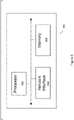
- Wireless device 110 includes transceiver 310, processor 320, and memory 330.
- transceiver 310 facilitates transmitting wireless signals to and receiving wireless signals from network node 115 (e.g., via antenna 340a)
- processor 320 executes instructions to provide some or all of the functionality described above as being provided by wireless device 110
- memory 330 stores the instructions executed by processor 320.
- Processor 320 may include any suitable combination of hardware and software implemented in one or more modules to execute instructions and manipulate data to perform some or all of the described functions of wireless device 110, such as the functions of wireless device 110 described above in relation to FIGURES 1-2 .
- processor 320 may include, for example, one or more computers, one or more central processing units (CPUs), one or more microprocessors, one or more applications, one or more application specific integrated circuits (ASICs), one or more field programmable gate arrays (FPGAs) and/or other logic.
- CPUs central processing units
- microprocessors one or more applications
- ASICs application specific integrated circuits
- FPGAs field programmable gate arrays
- Memory 330 is generally operable to store instructions, such as a computer program, software, an application including one or more of logic, rules, algorithms, code, tables, etc. and/or other instructions capable of being executed by a processor.
- Examples of memory 330 include computer memory (for example, Random Access Memory (RAM) or Read Only Memory (ROM)), mass storage media (for example, a hard disk), removable storage media (for example, a Compact Disk (CD) or a Digital Video Disk (DVD)), and/or or any other volatile or non-volatile, non-transitory computer-readable and/or computer-executable memory devices that store information, data, and/or instructions that may be used by processor 320.
- RAM Random Access Memory
- ROM Read Only Memory
- mass storage media for example, a hard disk
- removable storage media for example, a Compact Disk (CD) or a Digital Video Disk (DVD)
- CD Compact Disk
- DVD Digital Video Disk
- wireless device 110 may include additional components beyond those shown in FIGURE 3 that may be responsible for providing certain aspects of the wireless device's functionality, including any of the functionality described above and/or any additional functionality (including any functionality necessary to support the solution described above).
- wireless device 110 may include input devices and circuits, output devices, and one or more synchronization units or circuits, which may be part of the processor 320.
- Input devices include mechanisms for entry of data into wireless device 110.
- input devices may include input mechanisms, such as a microphone, input elements, a display, etc.
- Output devices may include mechanisms for outputting data in audio, video and/or hard copy format.
- output devices may include a speaker, a display, etc.
- FIGURE 4 is a block schematic of an exemplary network node, in accordance with certain embodiments.
- Network node 115 may be any type of radio network node or any network node that communicates with a UE and/or with another network node.
- Examples of network node 115 include an eNodeB, a node B, a base station, a wireless access point (e.g., a Wi-Fi access point), a low power node, a base transceiver station (BTS), relay, donor node controlling relay, transmission points, transmission nodes, remote RF unit (RRU), remote radio head (RRH), multi-standard radio (MSR) radio node such as MSR BS, nodes in distributed antenna system (DAS), O&M, OSS, SON, positioning node (e.g., E-SMLC), MDT, an RSU, or any other suitable network node.
- MSR multi-standard radio
- Network nodes 115 may be deployed throughout network 100 as a homogenous deployment, heterogeneous deployment, or mixed deployment.
- a homogeneous deployment may generally describe a deployment made up of the same (or similar) type of network nodes 115 and/or similar coverage and cell sizes and inter-site distances.
- a heterogeneous deployment may generally describe deployments using a variety of types of network nodes 115 having different cell sizes, transmit powers, capacities, and inter-site distances.
- a heterogeneous deployment may include a plurality of low-power nodes placed throughout a macro-cell layout.
- Mixed deployments may include a mix of homogenous portions and heterogeneous portions.
- Network node 115 may include one or more of transceiver 410, processor 420, memory 430, and network interface 440.
- transceiver 410 facilitates transmitting wireless signals to and receiving wireless signals from wireless device 110 (e.g., via antenna 440a)
- processor 420 executes instructions to provide some or all of the functionality described above as being provided by a network node 115
- memory 430 stores the instructions executed by processor 420
- network interface 440 communicates signals to backend network components, such as a gateway, switch, router, Internet, Public Switched Telephone Network (PSTN), core network nodes or radio network controllers 130, etc.
- PSTN Public Switched Telephone Network
- Processor 420 may include any suitable combination of hardware and software implemented in one or more modules to execute instructions and manipulate data to perform some or all of the described functions of network node 115, such as those described above in relation to FIGURES 1-2 above.
- processor 420 may include, for example, one or more computers, one or more central processing units (CPUs), one or more microprocessors, one or more applications, and/or other logic.
- Memory 430 is generally operable to store instructions, such as a computer program, software, an application including one or more of logic, rules, algorithms, code, tables, etc. and/or other instructions capable of being executed by a processor.
- Examples of memory 430 include computer memory (for example, Random Access Memory (RAM) or Read Only Memory (ROM)), mass storage media (for example, a hard disk), removable storage media (for example, a Compact Disk (CD) or a Digital Video Disk (DVD)), and/or or any other volatile or non-volatile, non-transitory computer-readable and/or computer-executable memory devices that store information.
- RAM Random Access Memory
- ROM Read Only Memory
- mass storage media for example, a hard disk
- removable storage media for example, a Compact Disk (CD) or a Digital Video Disk (DVD)
- CD Compact Disk
- DVD Digital Video Disk
- network interface 440 is communicatively coupled to processor 420 and may refer to any suitable device operable to receive input for network node 115, send output from network node 115, perform suitable processing of the input or output or both, communicate to other devices, or any combination of the preceding.
- Network interface 440 may include appropriate hardware (e.g., port, modem, network interface card, etc.) and software, including protocol conversion and data processing capabilities, to communicate through a network.
- network node 115 may include additional components beyond those shown in FIGURE 4 that may be responsible for providing certain aspects of the radio network node's functionality, including any of the functionality described above and/or any additional functionality (including any functionality necessary to support the solutions described above).
- the various different types of network nodes may include components having the same physical hardware but configured (e.g., via programming) to support different radio access technologies, or may represent partly or entirely different physical components.
- FIGURE 5 is a block schematic of an exemplary radio network controller or core network node 130, in accordance with certain embodiments.
- network nodes can include a mobile switching center (MSC), a serving GPRS support node (SGSN), a mobility management entity (MME), a radio network controller (RNC), a base station controller (BSC), and so on.
- the radio network controller or core network node 130 includes processor 520, memory 530, and network interface 540.
- processor 520 executes instructions to provide some or all of the functionality described above as being provided by the network node
- memory 530 stores the instructions executed by processor 520
- network interface 540 communicates signals to any suitable node, such as a gateway, switch, router, Internet, Public Switched Telephone Network (PSTN), network nodes 115, radio network controllers or core network nodes 130, etc.
- PSTN Public Switched Telephone Network
- Processor 520 may include any suitable combination of hardware and software implemented in one or more modules to execute instructions and manipulate data to perform some or all of the described functions of the radio network controller or core network node 130.
- processor 520 may include, for example, one or more computers, one or more central processing units (CPUs), one or more microprocessors, one or more applications, and/or other logic.
- CPUs central processing units
- microprocessors one or more applications, and/or other logic.
- Memory 530 is generally operable to store instructions, such as a computer program, software, an application including one or more of logic, rules, algorithms, code, tables, etc. and/or other instructions capable of being executed by a processor.
- Examples of memory 530 include computer memory (for example, Random Access Memory (RAM) or Read Only Memory (ROM)), mass storage media (for example, a hard disk), removable storage media (for example, a Compact Disk (CD) or a Digital Video Disk (DVD)), and/or or any other volatile or non-volatile, non-transitory computer-readable and/or computer-executable memory devices that store information.
- RAM Random Access Memory
- ROM Read Only Memory
- mass storage media for example, a hard disk
- removable storage media for example, a Compact Disk (CD) or a Digital Video Disk (DVD)
- CD Compact Disk
- DVD Digital Video Disk
- network interface 540 is communicatively coupled to processor 520 and may refer to any suitable device operable to receive input for the network node, send output from the network node, perform suitable processing of the input or output or both, communicate to other devices, or any combination of the preceding.
- Network interface 540 may include appropriate hardware (e.g., port, modem, network interface card, etc.) and software, including protocol conversion and data processing capabilities, to communicate through a network.
- network node may include additional components beyond those shown in FIGURE 5 that may be responsible for providing certain aspects of the network node's functionality, including any of the functionality described above and/or any additional functionality (including any functionality necessary to support the solution described above).
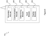
- FIGURE 6 is a block schematic of an exemplary wireless device, in accordance with certain embodiments.
- Wireless device 110 may include one or more modules.
- wireless device 110 may include a determining module 610, a communication module 620, a receiving module 630, an input module 640, a display module 650, and any other suitable modules.
- Wireless device 110 may perform the methods for per-packet resource pool selection described above with respect to FIGURES 1-2 .
- Determining module 610 may perform the processing functions of wireless device 110. As one example, determining module 610 may generate a tag for an associated data packet at a first layer, the generated tag indicating one or more parameters related to transmission of the associated data packet. As another example, determining module 610 may map, at the another layer, the associated data packet to a logical channel based on the one or more parameters indicated by the tag. As still another example, determining module 610 may select one or more resources for transmission of the associated data packet based on the mapping of the associated data packet to the logical channel. As yet another example, determining module 610 may select, based on the tag, one or more of: a power level for transmission of the associated data packet; and a transmission format for transmission of the associated data packet.
- determining module 610 may obtain a mapping for use in mapping the associated data packet to the logical channel based on the one or more parameters indicated by the tag. In certain embodiments, in obtaining the mapping for use in mapping the associated data packet to the logical channel based on the one or more parameters indicated by the tag, determining module 610 may determine the mapping for use in mapping the associated data packet to the logical channel based on the one or more parameters indicated by the tag.
- Determining module 610 may include or be included in one or more processors, such as processor 320 described above in relation to FIGURE 3 .
- Determining module 610 may include analog and/or digital circuitry configured to perform any of the functions of determining module 610 and/or processor 320 described above. The functions of determining module 610 described above may, in certain embodiments, be performed in one or more distinct modules.
- Communication module 620 may perform the transmission functions of wireless device 110. For example, communication module 620 may signal the tag from the first layer to another layer. As another example, communication module 620 may transmit the associated data packet using the one or more resources selected for transmission of the associated data packet. As still another example, communication module 620 may transmit the tag to one or more other nodes before the associated data packet is transmitted. Communication module 620 may transmit messages to one or more of network nodes 115 of network 100. Communication module 620 may include a transmitter and/or a transceiver, such as transceiver 310 described above in relation to FIGURE 3 . Communication module 620 may include circuitry configured to wirelessly transmit messages and/or signals. In particular embodiments, communication module 620 may receive messages and/or signals for transmission from determining module 610. In certain embodiments, the functions of communication module 620 described above may be performed in one or more distinct modules.
- Receiving module 630 may perform the receiving functions of wireless device 110. As one example, receiving module 630 may obtain a mapping for use in mapping the associated data packet to the logical channel based on the one or more parameters indicated by the tag. In certain embodiments, in obtaining the mapping for use in mapping the associated data packet to the logical channel based on the one or more parameters indicated by the tag, receiving module 630 may receive a mapping for use in mapping the associated data packet to the logical channel based on the tag. As another example, receiving module 630 may receive, from a second node, a second tag for a second associated data packet before receiving the second associated data packet.
- Receiving module 630 may include a receiver and/or a transceiver, such as transceiver 310 described above in relation to FIGURE 3 .
- Receiving module 630 may include circuitry configured to wirelessly receive messages and/or signals.
- receiving module 630 may communicate received messages and/or signals to determining module 610.
- Input module 640 may receive user input intended for wireless device 110.
- the input module may receive key presses, button presses, touches, swipes, audio signals, video signals, and/or any other appropriate signals.
- the input module may include one or more keys, buttons, levers, switches, touchscreens, microphones, and/or cameras.
- the input module may communicate received signals to determining module 610.
- Display module 650 may present signals on a display of wireless device 110.
- Display module 650 may include the display and/or any appropriate circuitry and hardware configured to present signals on the display.
- Display module 650 may receive signals to present on the display from determining module 610.
- Determining module 610, communication module 620, receiving module 630, input module 640, and display module 650 may include any suitable configuration of hardware and/or software.
- Wireless device 110 may include additional modules beyond those shown in FIGURE 6 that may be responsible for providing any suitable functionality, including any of the functionality described above and/or any additional functionality (including any functionality necessary to support the various solutions described herein).
- FIGURE 7 is a block schematic of an exemplary network node 115, in accordance with certain embodiments.
- Network node 115 may include one or more modules.
- network node 115 may include determining module 710, communication module 720, receiving module 730, and any other suitable modules.
- one or more of determining module 710, communication module 720, receiving module 730, or any other suitable module may be implemented using one or more processors, such as processor 420 described above in relation to FIGURE 4 .
- the functions of two or more of the various modules may be combined into a single module.
- Network node 115 may perform the methods for per-packet resource pool selection described above with respect to FIGURES 1-2 .
- Determining module 710 may perform the processing functions of network node 115. For example, determining module 710 may generate a tag for an associated data packet at a first layer, the generated tag indicating one or more parameters related to transmission of the associated data packet. As another example, determining module 710 may map, at the another layer, the associated data packet to a logical channel based on the one or more parameters indicated by the tag. As still another example, determining module 710 may select one or more resources for transmission of the associated data packet based on the mapping of the associated data packet to the logical channel. As yet another example, determining module 710 may select, based on the tag, one or more of: a power level for transmission of the associated data packet; and a transmission format for transmission of the associated data packet.
- determining module 710 may obtain a mapping for use in mapping the associated data packet to the logical channel based on the one or more parameters indicated by the tag. In certain embodiments, in obtaining the mapping for use in mapping the associated data packet to the logical channel based on the one or more parameters indicated by the tag, determining module 710 may determine the mapping for use in mapping the associated data packet to the logical channel based on the one or more parameters indicated by the tag.
- Determining module 710 may include or be included in one or more processors, such as processor 420 described above in relation to FIGURE 4 .
- Determining module 710 may include analog and/or digital circuitry configured to perform any of the functions of determining module 710 and/or processor 420 described above.
- the functions of determining module 710 may, in certain embodiments, be performed in one or more distinct modules. For example, in certain embodiments some of the functionality of determining module 710 may be performed by an allocation module.
- Communication module 720 may perform the transmission functions of network node 115. As one example, communication module 720 may signal the tag from the first layer to another layer. As another example, communication module 720 may transmit the associated data packet using the one or more resources selected for transmission of the associated data packet. As still another example, communication module 720 may transmit the tag to one or more other nodes before the associated data packet is transmitted. Communication module 720 may transmit messages to one or more of wireless devices 110. Communication module 720 may include a transmitter and/or a transceiver, such as transceiver 410 described above in relation to FIGURE 4 . Communication module 720 may include circuitry configured to wirelessly transmit messages and/or signals. In particular embodiments, communication module 720 may receive messages and/or signals for transmission from determining module 710 or any other module.
- Receiving module 730 may perform the receiving functions of network node 115. For example, receiving module 730 may obtain a mapping for use in mapping the associated data packet to the logical channel based on the one or more parameters indicated by the tag. In certain embodiments, in obtaining the mapping for use in mapping the associated data packet to the logical channel based on the one or more parameters indicated by the tag, receiving module 730 may receive a mapping for use in mapping the associated data packet to the logical channel based on the tag. As another example, receiving module 730 may receive, from a second node, a second tag for a second associated data packet before receiving the second associated data packet. Receiving module 730 may receive any suitable information from a wireless device.
- Receiving module 730 may include a receiver and/or a transceiver, such as transceiver 410 described above in relation to FIGURE 4 .
- Receiving module 730 may include circuitry configured to wirelessly receive messages and/or signals.
- receiving module 730 may communicate received messages and/or signals to determining module 710 or any other suitable module.
- Determining module 710, communication module 720, and receiving module 730 may include any suitable configuration of hardware and/or software.
- Network node 115 may include additional modules beyond those shown in FIGURE 7 that may be responsible for providing any suitable functionality, including any of the functionality described above and/or any additional functionality (including any functionality necessary to support the various solutions described herein).
- FIGURE 8 is a block diagram illustrating an example embodiment of a network, in accordance with certain embodiments. More particularly, FIGURE 8 illustrates a wireless network comprising a detailed view of wireless device 110 and network nodes 115. For simplicity, FIGURE 8 only depicts network 120, network nodes 115a and 115b, and wireless device 110. Wireless device 110 and network nodes 115a and 115b may perform the methods for per-packet resource pool selection described above with respect to FIGURES 1-2 .
- network node 115a comprises interface 440, processor 420, storage 430, and antenna 440a.
- wireless device 110 comprises interface 340, processor 320, storage 330, and antenna 340a. These components may work together in order to provide network node and/or wireless device functionality, such as providing wireless connections in a wireless network.
- network 120 may comprise any number of wired or wireless networks, network nodes, base stations, controllers, wireless devices, relay stations, and/or any other components that may facilitate or participate in the communication of data and/or signals whether via wired or wireless connections.
- Network 120 may comprise one or more IP networks, public switched telephone networks (PSTNs), packet data networks, optical networks, wide area networks (WANs), local area networks (LANs), wireless local area networks (WLANs), wired networks, wireless networks, metropolitan area networks, and other networks to enable communication between devices.
- PSTNs public switched telephone networks
- WANs wide area networks
- LANs local area networks
- WLANs wireless local area networks
- wired networks wireless networks, metropolitan area networks, and other networks to enable communication between devices.
- Network node 115a comprises interface 440, processor 420, storage 430, and antenna 440a. These components are depicted as single boxes located within a single larger box. In practice however, network node 115a may comprise multiple different physical components that make up a single illustrated component (e.g., interface 440 may comprise terminals for coupling wires for a wired connection and a radio transceiver for a wireless connection). Similarly, network node 115a may be composed of multiple physically separate components (e.g., a NodeB component and a Radio Network Controller (RNC) component, a base transceiver station (BTS) component and a base station controller (BSC) component, etc.), which may each have their own respective processor, storage, and interface components.
- RNC Radio Network Controller
- BTS base transceiver station
- BSC base station controller
- network node 115a comprises multiple separate components (e.g., BTS and BSC components)
- one or more of the separate components may be shared among several network nodes.
- a single RNC may control multiple NodeBs.
- each unique NodeB and BSC pair may be a separate network node.
- network node 115a may be configured to support multiple radio access technologies (RATs).
- RATs radio access technologies
- some components may be duplicated (e.g., separate storage 430 for the different RATs) and some components may be reused (e.g., the same antenna 440a may be shared by the RATs).
- Processor 420 may be a combination of one or more of a microprocessor, controller, microcontroller, central processing unit, digital signal processor, application specific integrated circuit, field programmable gate array, or any other suitable computing device, resource, or combination of hardware, software and/or encoded logic operable to provide, either alone or in conjunction with other network node 200 components, such as storage 430, network node 200 functionality.
- processor 420 may execute instructions stored in storage 430.
- Such functionality may include providing various wireless features discussed herein to a wireless devices, such as wireless device 110a, including any of the features or benefits disclosed herein.
- Storage 430 may comprise any form of volatile or non-volatile computer readable memory including, without limitation, persistent storage, solid state memory, remotely mounted memory, magnetic media, optical media, random access memory (RAM), read-only memory (ROM), removable media, or any other suitable local or remote memory component.
- Storage 430 may store any suitable instructions, data or information, including software and encoded logic, utilized by network node 200. Storage 430 may be used to store any calculations made by processor 420 and/or any data received via interface 440.
- Network node 115a also comprises interface 440 which may be used in the wired or wireless communication of signalling and/or data between network node 115a, network 120, and/or wireless device 110.
- interface 440 may perform any formatting, coding, or translating that may be needed to allow network node 115a to send and receive data from network 120 over a wired connection.
- Interface 440 may also include a radio transmitter and/or receiver that may be coupled to or a part of antenna 440a.
- the radio may receive digital data that is to be sent out to other network nodes or wireless devices via a wireless connection.
- the radio may convert the digital data into a radio signal having the appropriate channel and bandwidth parameters.
- the radio signal may then be transmitted via antenna 440a to the appropriate recipient (e.g., wireless device 110).
- Antenna 440a may be any type of antenna capable of transmitting and receiving data and/or signals wirelessly.
- antenna 440a may comprise one or more omni-directional, sector or panel antennas operable to transmit/receive radio signals between, for example, 2 GHz and 66 GHz.
- An omni-directional antenna may be used to transmit/receive radio signals in any direction.
- a sector antenna may be used to transmit/receive radio signals from devices within a particular area.
- a panel antenna may be a line of sight antenna used to transmit/receive radio signals in a relatively straight line.
- Wireless device 110 may be any type of wireless endpoint, mobile station, mobile phone, wireless local loop phone, smartphone, user equipment, desktop computer, PDA, cell phone, tablet, laptop, VoIP phone or handset, which is able to wirelessly send and receive data and/or signals to and from a network node, such as network node 115a and/or other wireless devices.
- Wireless device 110 comprises processor 320, storage 330, interface 340, and antenna 340a.
- the components of wireless device 110 are depicted as single boxes located within a single larger box, however in practice a wireless device may comprises multiple different physical components that make up a single illustrated component (e.g., storage 330 may comprise multiple discrete microchips, each microchip representing a portion of the total storage capacity).
- Processor 320 may be a combination of one or more of a microprocessor, controller, microcontroller, central processing unit, digital signal processor, application specific integrated circuit, field programmable gate array, or any other suitable computing device, resource, or combination of hardware, software and/or encoded logic operable to provide, either alone or in combination with other wireless device 110 components, such as storage 330, wireless device 110 functionality.
- Such functionality may include providing various wireless features discussed herein, including any of the features or benefits disclosed herein.
- Storage 330 may be any form of volatile or non-volatile memory including, without limitation, persistent storage, solid state memory, remotely mounted memory, magnetic media, optical media, random access memory (RAM), read-only memory (ROM), removable media, or any other suitable local or remote memory component.
- Storage 330 may store any suitable data, instructions, or information, including software and encoded logic, utilized by wireless device 210.
- Storage 330 may be used to store any calculations made by processor 320 and/or any data received via interface 340.
- Interface 340 may be used in the wireless communication of signalling and/or data between wireless device 110 and network node 115a.
- interface 340 may perform any formatting, coding, or translating that may be needed to allow wireless device 110 to send and receive data from network node 115a over a wireless connection.
- Interface 340 may also include a radio transmitter and/or receiver that may be coupled to or a part of antenna 340a.
- the radio may receive digital data that is to be sent out to network node 115a via a wireless connection.
- the radio may convert the digital data into a radio signal having the appropriate channel and bandwidth parameters.
- the radio signal may then be transmitted via antenna 340a to network node 115a.
- Antenna 340a may be any type of antenna capable of transmitting and receiving data and/or signals wirelessly.
- antenna 340a may comprise one or more omni-directional, sector or panel antennas operable to transmit/receive radio signals between 2 GHz and 66 GHz.
- antenna 340a may be considered a part of interface 340 to the extent that a wireless signal is being used.
- storage 430 may comprise computer readable means on which a computer program can be stored.
- the computer program may include instructions which cause processor 420 (and any operatively coupled entities and devices, such as interface 440 and storage 430) to execute methods according to embodiments described herein.
- the computer program and/or computer program product may thus provide means for performing any steps herein disclosed.
- Each functional module may comprise software, computer programs, sub-routines, libraries, source code, or any other form of executable instructions that are executed by, for example, a processor.
- each functional module may be implemented in hardware and/or in software.
- one or more or all functional modules may be implemented by processors 320 and/or 420, possibly in cooperation with storage 330 and/or 430.
- Processors 320 and/or 420 and storage 330 and/or 430 may thus be arranged to allow processors 320 and/or 420 to fetch instructions from storage 330 and/or 430 and execute the fetched instructions to allow the respective functional module to perform any steps or functions disclosed herein.
Landscapes
- Engineering & Computer Science (AREA)
- Signal Processing (AREA)
- Computer Networks & Wireless Communication (AREA)
- Quality & Reliability (AREA)
- Mobile Radio Communication Systems (AREA)
- Data Exchanges In Wide-Area Networks (AREA)
Claims (15)
- Verfahren, das in einem Knoten (110, 115), der in einem Verkehrsvernetzungs-,V2X-,System betrieben werden kann, durchgeführt wird und umfasst:Erzeugen (204) eines Tags, das mit einem V2X-Datenpaket assoziiert ist, auf einer ersten Schicht, wobei das Tag einen oder mehrere Parameter angibt, die mit Übertragung des assoziierten V2X-Datenpakets in Beziehung stehen;Signalisieren (208) des Tags von der ersten Schicht an eine untere Schicht;Zuordnen (212) des assoziierten V2X-Datenpakets auf der unteren Schicht zu einem logischen Kanal basierend auf dem einen oder den mehreren Parametern, die durch das Tag angegeben werden; undAuswählen (216) einer oder mehrerer Ressourcen zur Übertragung des assoziierten V2X-Datenpakets basierend auf der Zuordnung des assoziierten V2X-Datenpakets zum logischen Kanal, wobei die erste Schicht eine Anwendungsschicht ist.
- Knoten (110, 115), der in einem Verkehrsvernetzungs-,V2X-,System betrieben werden kann und umfasst:
einen oder mehrere Prozessoren (320, 420), wobei der eine oder die mehreren Prozessoren (320, 420) konfiguriert sind zum:Erzeugen (204) eines Tags, das mit einem V2X-Datenpaket assoziiert ist, auf einer ersten Schicht, wobei das Tag einen oder mehrere Parameter angibt, die mit Übertragung des assoziierten V2X-Datenpakets in Beziehung stehen;Signalisieren (208) des Tags von der ersten Schicht an eine untere Schicht;Zuordnen (212) des assoziierten V2X-Datenpakets auf der unteren Schicht zu einem logischen Kanal basierend auf dem einen oder den mehreren Parametern, die durch das Tag angegeben werden; undAuswählen (216) einer oder mehrerer Ressourcen zur Übertragung des assoziierten V2X-Datenpakets basierend auf der Zuordnung des assoziierten V2X-Datenpakets zum logischen Kanal, wobei die erste Schicht eine Anwendungsschicht ist. - Knoten (110, 115) nach Anspruch 2, wobei der eine oder die mehreren Parameter eines oder mehrere umfassen von:einem Verkehrstyp des assoziierten V2X-Datenpakets;einer Periodizität des assoziierten V2X-Datenpakets;einer Latenzanforderung des assoziierten V2X-Datenpakets;einer Priorität des assoziierten V2X-Datenpakets;einem Gerätetyp des Knotens (110, 115);einem Vorhandensein einer externen Leistungsquelle für den Knoten (110, 115); undeinem Batteriestand des Knotens (110, 115).
- Knoten (110, 115) nach Anspruch 3, wobei der Verkehrstyp des assoziierten V2X-Datenpakets durch eine Zielgruppe angegeben wird, und/oder wobei die Periodizität des assoziierten V2X-Datenpakets durch die Priorität des assoziierten V2X-Datenpakets angegeben wird.
- Knoten (110, 115) nach Anspruch 2, wobei der eine oder die mehreren Prozessoren (320, 420) so konfiguriert sind, dass sie einen Leistungspegel zur Übertragung des assoziierten V2X-Datenpakets basierend auf dem Tag auswählen.
- Knoten (110, 115) nach Anspruch 2, wobei der eine oder die mehreren Prozessoren (320, 420) so konfiguriert sind, dass sie eine Zuordnung zur Verwendung beim Zuordnen des assoziierten V2X-Datenpakets zum logischen Kanal basierend auf dem einen oder den mehreren Parametern erhalten, die durch das Tag angegeben werden.
- Knoten (110, 115) nach Anspruch 6, wobei der eine oder die mehreren Prozessoren (320, 420), die so konfiguriert sind, dass sie die Zuordnung zur Verwendung beim Zuordnen des assoziierten V2X-Datenpakets zum logischen Kanal basierend auf dem einen oder den mehreren Parametern erhalten, die durch das Tag angegeben werden, einen oder mehrere Prozessoren (320) 420) umfassen, die konfiguriert sind zum:
Bestimmen der Zuordnung zur Verwendung beim Zuordnen des assoziierten V2X-Datenpakets zum logischen Kanal durch den Knoten (110, 115) basierend auf dem einen oder den mehreren Parametern, die durch das Tag angegeben werden. - Knoten (110, 115) nach Anspruch 6, wobei der eine oder die mehreren Prozessoren (320, 420), die so konfiguriert sind, dass sie die Zuordnung zur Verwendung beim Zuordnen des assoziierten V2X-Datenpakets zum logischen Kanal basierend auf dem einen oder den mehreren Parametern erhalten, die durch das Tag angegeben werden, einen oder mehrere Prozessoren (320, 420) umfassen, die konfiguriert sind zum:
Empfangen einer Zuordnung zur Verwendung beim Zuordnen des assoziierten V2X-Datenpakets zum logischen Kanal basierend auf dem Tag. - Knoten (110, 115) nach Anspruch 2, wobei der eine oder die mehreren Prozessoren (320, 420), die so konfiguriert sind, dass sie das assoziierte V2X-Datenpaket basierend auf dem einen oder den mehreren Parametern, die durch das Tag angegeben werden, einem logischen Kanal zuordnen, einen oder mehrere Prozessoren (320) 420) umfassen, die so konfiguriert sind, dass sie das Tag einem dedizierten Funkträger zuordnen.
- Knoten (110, 115) nach Anspruch 9, wobei die Zuordnung eine Eins-zu-eins-Zuordnung umfasst, oder wobei eine Mehrzahl von Tags einem einzigen dedizierten Funkträger zugeordnet werden kann.
- Knoten (110, 115) nach Anspruch 2, wobei der eine oder die mehreren Prozessoren (320, 420) so konfiguriert sind, dass sie das assoziierte Datenpaket unter Verwendung der einen oder der mehreren Ressourcen übertragen, die zur Übertragung des assoziierten Datenpakets ausgewählt wurden.
- Knoten (110, 115) nach Anspruch 2, wobei der eine oder die mehreren Prozessoren (320, 420) so konfiguriert sind, dass sie das Tag an einen oder mehrere andere Knoten übertragen, bevor das assoziierte V2X-Datenpaket übertragen wird.
- Knoten (110, 115) nach Anspruch 2, wobei:der Knoten (110, 115) ein erster Knoten ist;das Tag ein erstes Tag ist;das assoziierte Datenpaket ein erstes assoziiertes V2X-Datenpaket ist;der eine oder die mehreren Prozessoren (320, 420) so konfiguriert sind, dass sie ein zweites Tag für ein zweites assoziiertes V2X-Datenpaket von einem zweiten Knoten empfangen, bevor sie das zweite assoziierte V2X-Datenpaket empfangen.
- Knoten (110, 115) nach Anspruch 2, wobei der eine oder die mehreren Prozessoren (320, 420) so konfiguriert sind, dass sie das Tag als Bitmap von der ersten Schicht an die untere Schicht signalisieren.
- Knoten (110, 115) nach Anspruch 2, wobei der Knoten (110, 115) eines umfasst von:einer drahtlosen Vorrichtung (110); undeinem Netzknoten (115).
Priority Applications (1)
| Application Number | Priority Date | Filing Date | Title |
|---|---|---|---|
| EP22183824.6A EP4099605B1 (de) | 2015-09-25 | 2016-09-21 | Ressourcenpoolauswahl per paket in einem lte-v2x system |
Applications Claiming Priority (2)
| Application Number | Priority Date | Filing Date | Title |
|---|---|---|---|
| CN2015090835 | 2015-09-25 | ||
| PCT/IB2016/055636 WO2017051330A1 (en) | 2015-09-25 | 2016-09-21 | Per-packet resource pool selection in lte v2x system |
Related Child Applications (2)
| Application Number | Title | Priority Date | Filing Date |
|---|---|---|---|
| EP22183824.6A Division-Into EP4099605B1 (de) | 2015-09-25 | 2016-09-21 | Ressourcenpoolauswahl per paket in einem lte-v2x system |
| EP22183824.6A Division EP4099605B1 (de) | 2015-09-25 | 2016-09-21 | Ressourcenpoolauswahl per paket in einem lte-v2x system |
Publications (2)
| Publication Number | Publication Date |
|---|---|
| EP3353939A1 EP3353939A1 (de) | 2018-08-01 |
| EP3353939B1 true EP3353939B1 (de) | 2022-08-17 |
Family
ID=57018159
Family Applications (2)
| Application Number | Title | Priority Date | Filing Date |
|---|---|---|---|
| EP16774549.6A Active EP3353939B1 (de) | 2015-09-25 | 2016-09-21 | Ressourcenpoolauswahl per paket in einem lte-v2x system |
| EP22183824.6A Active EP4099605B1 (de) | 2015-09-25 | 2016-09-21 | Ressourcenpoolauswahl per paket in einem lte-v2x system |
Family Applications After (1)
| Application Number | Title | Priority Date | Filing Date |
|---|---|---|---|
| EP22183824.6A Active EP4099605B1 (de) | 2015-09-25 | 2016-09-21 | Ressourcenpoolauswahl per paket in einem lte-v2x system |
Country Status (6)
| Country | Link |
|---|---|
| US (4) | US10764903B2 (de) |
| EP (2) | EP3353939B1 (de) |
| JP (1) | JP6686132B2 (de) |
| PH (1) | PH12018500536A1 (de) |
| RU (1) | RU2682909C1 (de) |
| WO (1) | WO2017051330A1 (de) |
Families Citing this family (27)
| Publication number | Priority date | Publication date | Assignee | Title |
|---|---|---|---|---|
| EP3353939B1 (de) * | 2015-09-25 | 2022-08-17 | Telefonaktiebolaget LM Ericsson (PUBL) | Ressourcenpoolauswahl per paket in einem lte-v2x system |
| WO2017111565A1 (ko) * | 2015-12-24 | 2017-06-29 | 엘지전자 주식회사 | 무선 통신 시스템에서 v2x 단말의 데이터 송신 방법 및 장치 |
| WO2017114552A1 (en) * | 2015-12-28 | 2017-07-06 | Telefonaktiebolaget Lm Ericsson (Publ) | Timing indication for controlling listen-before-talk procedure |
| US11228869B2 (en) * | 2017-03-31 | 2022-01-18 | Intel Corporation | Roadway communication system with multicast |
| CN109152076B (zh) * | 2017-06-27 | 2022-04-05 | 华为云计算技术有限公司 | 一种通信资源调度的方法、装置和系统 |
| CN109548076B (zh) * | 2017-08-02 | 2020-12-08 | 华为技术有限公司 | 数据重复传输方法和设备 |
| CN110720229A (zh) * | 2017-08-18 | 2020-01-21 | Oppo广东移动通信有限公司 | 无线通信的方法、终端设备和网络设备 |
| US11564070B2 (en) * | 2017-10-06 | 2023-01-24 | Qualcomm Incorporated | Vehicle to everything (V2X) radio access technology (RAT) feature negotiation and control |
| CN111279743B (zh) * | 2017-10-26 | 2023-07-18 | 华为技术有限公司 | 服务质量变化通知技术 |
| US11323859B2 (en) * | 2017-11-15 | 2022-05-03 | Nokia Technologies Oy | Vehicular message delivery |
| WO2019160489A1 (en) | 2018-02-15 | 2019-08-22 | Telefonaktiebolaget Lm Ericsson (Publ) | Wireless device, radio network node and methods performed therein |
| TWI711327B (zh) | 2018-04-03 | 2020-11-21 | 美商Idac控股公司 | 合作車間有效資源使用方法 |
| CN110545536B (zh) * | 2018-05-29 | 2021-10-01 | 中兴通讯股份有限公司 | 一种d2d通信资源池数据传输的方法及装置 |
| US10594420B2 (en) | 2018-05-31 | 2020-03-17 | At&T Intellectual Property I, L.P. | Cellular broadcast messaging and indirection |
| US10909866B2 (en) * | 2018-07-20 | 2021-02-02 | Cybernet Systems Corp. | Autonomous transportation system and methods |
| US12004001B2 (en) | 2018-08-09 | 2024-06-04 | Telefonaktiebolaget Lm Ericsson (Publ) | Method and system for exchanging information for sidelink communication in a wireless network |
| EP3854158A1 (de) * | 2018-09-19 | 2021-07-28 | Telefonaktiebolaget LM Ericsson (publ) | Verfahren zur ressourcenauswahl für sidelink-richtkommunikation |
| CN111132371B (zh) * | 2018-11-01 | 2022-03-11 | 维沃移动通信有限公司 | 副链路连接建立、资源分配方法、终端及网络侧设备 |
| US10834549B2 (en) * | 2018-12-26 | 2020-11-10 | King Fahd University Of Petroleum And Minerals | Internet of things for healthcare monitoring applications based on RFID clustering scheme |
| KR102611775B1 (ko) * | 2019-01-30 | 2023-12-11 | 삼성전자 주식회사 | 그룹 메시지의 전달 방법 및 이를 수행하는 전자 장치 |
| CN114466383A (zh) | 2019-04-01 | 2022-05-10 | 华为技术有限公司 | 数据处理方法和信息处理装置 |
| KR102806827B1 (ko) * | 2019-05-02 | 2025-05-13 | 삼성전자 주식회사 | 단말 직접 통신시스템에서 패킷 송수신 영역 결정 방법 및 장치 |
| CN110234095B (zh) * | 2019-06-11 | 2022-04-15 | 南京林业大学 | 接收到位图情况下的冲突检测避免方法 |
| KR102832131B1 (ko) * | 2019-06-25 | 2025-07-09 | 엘지전자 주식회사 | 통신 모드 전환 장치 및 방법 |
| US11792616B2 (en) * | 2019-09-27 | 2023-10-17 | Intel Corporation | Distributed network allocation vector management for enabling vehicle-to-everything radio access technology coexistence |
| EP4020429B1 (de) * | 2020-12-22 | 2024-07-17 | Mitsubishi Electric R&D Centre Europe B.V. | Vru-parameteraktualisierung |
| DE102021213403A1 (de) | 2021-11-29 | 2023-06-01 | Robert Bosch Gesellschaft mit beschränkter Haftung | Verfahren zum Kommunizieren zwischen einem Kraftfahrzeug und einer Infrastruktur |
Citations (1)
| Publication number | Priority date | Publication date | Assignee | Title |
|---|---|---|---|---|
| US20080175237A1 (en) * | 2007-01-23 | 2008-07-24 | Samsung Electronics Co., Ltd. | Apparatus and method for transmitting service guide in broadband wireless access system |
Family Cites Families (37)
| Publication number | Priority date | Publication date | Assignee | Title |
|---|---|---|---|---|
| GB0522941D0 (en) * | 2005-11-10 | 2005-12-21 | Ibm | Method, apparatus and computer program product for determining a destination at which a group of devices can store data associated with the devices |
| US20100002699A1 (en) * | 2008-07-01 | 2010-01-07 | Sony Corporation | Packet tagging for effective multicast content distribution |
| US9100585B2 (en) * | 2008-10-28 | 2015-08-04 | Sony Computer Entertainment Inc. | Combined broadcast and backchannel delivery of streaming content |
| US8325727B2 (en) * | 2010-04-08 | 2012-12-04 | Calix, Inc. | Inline packet replication in network devices |
| WO2013009635A2 (en) * | 2011-07-08 | 2013-01-17 | Interdigital Patent Holdings, Inc. | Component carrier traffic mapping |
| US20140307600A1 (en) * | 2013-04-15 | 2014-10-16 | Nokia Corporation | Method, apparatus, and computer program product for reducing power consumption for wireless communications |
| US9992809B2 (en) * | 2013-06-13 | 2018-06-05 | Telefonaktiebolaget Lm Ericsson (Publ) | Controlling vehicle-to-vehicle communication using a distribution scheme |
| US9734754B2 (en) | 2013-09-10 | 2017-08-15 | Sharp Kabushiki Kaisha | Display device and method for driving same |
| WO2015103733A1 (en) | 2014-01-07 | 2015-07-16 | Qualcomm Incorporated | TWO SUBFRAME SET CSI FEEDBACK FOR eIMTA IN LTE |
| CN105981433B (zh) * | 2014-02-10 | 2019-09-10 | Lg电子株式会社 | 无线通信系统中指示d2d数据的qos的方法和装置 |
| US10045249B2 (en) * | 2014-03-19 | 2018-08-07 | Lg Electronics Inc. | Method and apparatus for configuring buffer status report for public safety transmission or vehicle-related transmission in wireless communication system |
| CN106664699B (zh) * | 2014-08-05 | 2020-06-05 | Lg电子株式会社 | 用于在无线通信系统中操作终端的方法和使用所述方法的终端 |
| US10149335B2 (en) * | 2014-11-10 | 2018-12-04 | Qualcomm Incorporated | Connectivity module for internet of things (IOT) devices |
| EP3051736B1 (de) * | 2015-01-30 | 2020-04-29 | Panasonic Intellectual Property Corporation of America | Priorisierung im Verfahren zur logischen Kanalpriorisierung für logische Sidelink-Kanäle in ProSe-Direktkommunikationen |
| US9799220B2 (en) * | 2015-02-04 | 2017-10-24 | Trw Automotive U.S. Llc | Keyless entry system linked to vehicle-to-vehicle communications system |
| US11057903B2 (en) * | 2015-04-01 | 2021-07-06 | Samsung Electronics Co., Ltd. | Method and apparatus for processing priority in D2D communication system |
| US20160295624A1 (en) * | 2015-04-02 | 2016-10-06 | Samsung Electronics Co., Ltd | Methods and apparatus for resource pool design for vehicular communications |
| WO2016163859A1 (ko) * | 2015-04-09 | 2016-10-13 | 엘지전자 주식회사 | 무선 통신 시스템에서 단말에 의해 수행되는 우선 순위 정보 전송 방법 및 상기 방법을 이용하는 단말 |
| WO2016173644A1 (en) * | 2015-04-29 | 2016-11-03 | Nokia Solutions And Networks Oy | Use of multiple device-to-device (d2d) discovery message resources for transmission of a service message in a wireless network |
| CN106211332B (zh) * | 2015-05-05 | 2021-08-17 | 中兴通讯股份有限公司 | 资源分配的方法和装置 |
| WO2016182292A1 (ko) * | 2015-05-08 | 2016-11-17 | 엘지전자 주식회사 | 무선 통신 시스템에서 단말의 v2x 통신 수행 방법 및 상기 방법을 이용하는 단말 |
| KR102441168B1 (ko) * | 2015-05-08 | 2022-09-07 | 삼성전자주식회사 | 차량 서비스를 위한 자원 할당 장치 및 방법 |
| WO2016185319A1 (en) * | 2015-05-15 | 2016-11-24 | Telefonaktiebolaget Lm Ericsson (Publ) | Device-to-device priority pool configuration |
| CN118574075A (zh) * | 2015-06-23 | 2024-08-30 | 交互数字专利控股公司 | 用于邻近服务通信的优先级处理 |
| KR102424678B1 (ko) * | 2015-06-24 | 2022-07-22 | 인텔 코포레이션 | 차량 대 사물(V2X) 통신을 위한 향상된 근접 서비스(ProSe) 프로토콜 |
| CN107852605A (zh) * | 2015-07-22 | 2018-03-27 | Lg 电子株式会社 | 在无线通信系统中授权车辆ue和rsu ue的方法和装置 |
| WO2017022958A1 (en) * | 2015-08-06 | 2017-02-09 | Lg Electronics Inc. | Method for receiving a priority for relay data in a d2d communication system and device therefor |
| EP3709761B1 (de) * | 2015-08-07 | 2022-02-16 | Samsung Electronics Co., Ltd. | Netzwerk-entitäten und verfahren dafür |
| CN112788573B (zh) * | 2015-08-12 | 2023-06-06 | Lg电子株式会社 | 用于在无线通信系统中操作的方法及无线装置 |
| US10412754B2 (en) * | 2015-08-12 | 2019-09-10 | Intel Corporation | Resource access in device to device communication |
| WO2017026667A1 (en) * | 2015-08-12 | 2017-02-16 | Lg Electronics Inc. | Method for performing a logical channel prioritization in a d2d communication system and device therefor |
| US11570754B2 (en) * | 2015-08-12 | 2023-01-31 | Interdigital Patent Holdings, Inc. | Methods, apparatus and systems for realizing vehicle to vehicle communications using long term evolution device to device communications |
| BR112018002927A2 (pt) * | 2015-08-14 | 2019-10-08 | Ericsson Telefon Ab L M | redução de colisões entre recursos de comunicação e de descoberta |
| EP3354061B1 (de) * | 2015-09-24 | 2020-12-09 | LG Electronics Inc. | Verfahren zum senden einer pufferstatusmeldung in einem d2d-kommunikationssystem und vorrichtung dafür |
| EP3148285B1 (de) * | 2015-09-25 | 2019-04-17 | Panasonic Intellectual Property Corporation of America | Verbesserte funkträgerzuordnung für endgerät zu netzwerk 3gpp proximity services relais mittels signalisierung der verbundene priorität |
| EP3353939B1 (de) * | 2015-09-25 | 2022-08-17 | Telefonaktiebolaget LM Ericsson (PUBL) | Ressourcenpoolauswahl per paket in einem lte-v2x system |
| EP3580974A4 (de) * | 2017-02-13 | 2020-12-02 | Telefonaktiebolaget LM Ericsson (publ) | Ressourcenauswahl basierend auf latenzanforderungen |
-
2016
- 2016-09-21 EP EP16774549.6A patent/EP3353939B1/de active Active
- 2016-09-21 WO PCT/IB2016/055636 patent/WO2017051330A1/en not_active Ceased
- 2016-09-21 EP EP22183824.6A patent/EP4099605B1/de active Active
- 2016-09-21 US US15/762,681 patent/US10764903B2/en active Active
- 2016-09-21 RU RU2018115150A patent/RU2682909C1/ru active
- 2016-09-21 JP JP2018515308A patent/JP6686132B2/ja active Active
-
2018
- 2018-03-12 PH PH12018500536A patent/PH12018500536A1/en unknown
-
2020
- 2020-08-20 US US16/998,927 patent/US11540293B2/en active Active
-
2022
- 2022-12-26 US US18/088,652 patent/US11956811B2/en active Active
-
2024
- 2024-04-09 US US18/630,107 patent/US20240260071A1/en not_active Abandoned
Patent Citations (1)
| Publication number | Priority date | Publication date | Assignee | Title |
|---|---|---|---|---|
| US20080175237A1 (en) * | 2007-01-23 | 2008-07-24 | Samsung Electronics Co., Ltd. | Apparatus and method for transmitting service guide in broadband wireless access system |
Also Published As
| Publication number | Publication date |
|---|---|
| US20240260071A1 (en) | 2024-08-01 |
| PH12018500536A1 (en) | 2018-09-24 |
| JP2018536318A (ja) | 2018-12-06 |
| US20200383116A1 (en) | 2020-12-03 |
| EP4099605B1 (de) | 2024-02-21 |
| EP4099605C0 (de) | 2024-02-21 |
| EP4099605A1 (de) | 2022-12-07 |
| WO2017051330A1 (en) | 2017-03-30 |
| RU2682909C1 (ru) | 2019-03-22 |
| US20180295628A1 (en) | 2018-10-11 |
| EP3353939A1 (de) | 2018-08-01 |
| US11956811B2 (en) | 2024-04-09 |
| US10764903B2 (en) | 2020-09-01 |
| US11540293B2 (en) | 2022-12-27 |
| JP6686132B2 (ja) | 2020-04-22 |
| US20230125319A1 (en) | 2023-04-27 |
Similar Documents
| Publication | Publication Date | Title |
|---|---|---|
| US11956811B2 (en) | Per-packet resource pool selection in LTE V2X system | |
| US12047805B2 (en) | Method and node for determining priority of data from a scheduling assignment | |
| CN114930975B (zh) | 对于n3iwf接入的ue到网络中继支持 | |
| CN109792769B (zh) | 用于为边链路操作进行资源感应的系统和方法 | |
| EP3231235B1 (de) | Transportformat für kommunikation | |
| EP3372021B1 (de) | Abfallmessungen von synchronisationssignalen | |
| US10499318B2 (en) | Provisioning transmission pools for inter-carrier prose direct discovery | |
| CN107113651B (zh) | 在无线通信系统中发送用于双向传输的缓冲器状态报告的方法和装置 | |
| EP3714624B1 (de) | Ortsbewusste planung | |
| EP3266266B1 (de) | An koordinationsinformationen eines anderen knoten adaptierte ressourcenkoordination im kontext von dezentralisierter kooperativer fahrzeugkommunikation | |
| US20180255585A1 (en) | User Equipment, Network Node and Methods Performed Therein | |
| US12464434B2 (en) | Sidelink relay routing options for transmission of data from wireless communication device to network | |
| AU2018300489A1 (en) | Electronic device and wireless communication method | |
| JP2024502959A (ja) | 部分センシングを伴うnrサイドリンクueのための選択ウィンドウおよびセンシングウィンドウの通信装置と通信方法 |
Legal Events
| Date | Code | Title | Description |
|---|---|---|---|
| STAA | Information on the status of an ep patent application or granted ep patent |
Free format text: STATUS: THE INTERNATIONAL PUBLICATION HAS BEEN MADE |
|
| PUAI | Public reference made under article 153(3) epc to a published international application that has entered the european phase |
Free format text: ORIGINAL CODE: 0009012 |
|
| STAA | Information on the status of an ep patent application or granted ep patent |
Free format text: STATUS: REQUEST FOR EXAMINATION WAS MADE |
|
| 17P | Request for examination filed |
Effective date: 20180308 |
|
| AK | Designated contracting states |
Kind code of ref document: A1 Designated state(s): AL AT BE BG CH CY CZ DE DK EE ES FI FR GB GR HR HU IE IS IT LI LT LU LV MC MK MT NL NO PL PT RO RS SE SI SK SM TR |
|
| AX | Request for extension of the european patent |
Extension state: BA ME |
|
| DAV | Request for validation of the european patent (deleted) | ||
| DAX | Request for extension of the european patent (deleted) | ||
| STAA | Information on the status of an ep patent application or granted ep patent |
Free format text: STATUS: EXAMINATION IS IN PROGRESS |
|
| 17Q | First examination report despatched |
Effective date: 20201028 |
|
| GRAP | Despatch of communication of intention to grant a patent |
Free format text: ORIGINAL CODE: EPIDOSNIGR1 |
|
| STAA | Information on the status of an ep patent application or granted ep patent |
Free format text: STATUS: GRANT OF PATENT IS INTENDED |
|
| INTG | Intention to grant announced |
Effective date: 20220309 |
|
| GRAS | Grant fee paid |
Free format text: ORIGINAL CODE: EPIDOSNIGR3 |
|
| GRAA | (expected) grant |
Free format text: ORIGINAL CODE: 0009210 |
|
| STAA | Information on the status of an ep patent application or granted ep patent |
Free format text: STATUS: THE PATENT HAS BEEN GRANTED |
|
| AK | Designated contracting states |
Kind code of ref document: B1 Designated state(s): AL AT BE BG CH CY CZ DE DK EE ES FI FR GB GR HR HU IE IS IT LI LT LU LV MC MK MT NL NO PL PT RO RS SE SI SK SM TR |
|
| REG | Reference to a national code |
Ref country code: CH Ref legal event code: EP |
|
| REG | Reference to a national code |
Ref country code: DE Ref legal event code: R096 Ref document number: 602016074357 Country of ref document: DE |
|
| REG | Reference to a national code |
Ref country code: IE Ref legal event code: FG4D |
|
| REG | Reference to a national code |
Ref country code: AT Ref legal event code: REF Ref document number: 1512867 Country of ref document: AT Kind code of ref document: T Effective date: 20220915 |
|
| REG | Reference to a national code |
Ref country code: NL Ref legal event code: MP Effective date: 20220817 |
|
| REG | Reference to a national code |
Ref country code: LT Ref legal event code: MG9D |
|
| PG25 | Lapsed in a contracting state [announced via postgrant information from national office to epo] |
Ref country code: SE Free format text: LAPSE BECAUSE OF FAILURE TO SUBMIT A TRANSLATION OF THE DESCRIPTION OR TO PAY THE FEE WITHIN THE PRESCRIBED TIME-LIMIT Effective date: 20220817 Ref country code: RS Free format text: LAPSE BECAUSE OF FAILURE TO SUBMIT A TRANSLATION OF THE DESCRIPTION OR TO PAY THE FEE WITHIN THE PRESCRIBED TIME-LIMIT Effective date: 20220817 Ref country code: PT Free format text: LAPSE BECAUSE OF FAILURE TO SUBMIT A TRANSLATION OF THE DESCRIPTION OR TO PAY THE FEE WITHIN THE PRESCRIBED TIME-LIMIT Effective date: 20221219 Ref country code: NO Free format text: LAPSE BECAUSE OF FAILURE TO SUBMIT A TRANSLATION OF THE DESCRIPTION OR TO PAY THE FEE WITHIN THE PRESCRIBED TIME-LIMIT Effective date: 20221117 Ref country code: NL Free format text: LAPSE BECAUSE OF FAILURE TO SUBMIT A TRANSLATION OF THE DESCRIPTION OR TO PAY THE FEE WITHIN THE PRESCRIBED TIME-LIMIT Effective date: 20220817 Ref country code: LV Free format text: LAPSE BECAUSE OF FAILURE TO SUBMIT A TRANSLATION OF THE DESCRIPTION OR TO PAY THE FEE WITHIN THE PRESCRIBED TIME-LIMIT Effective date: 20220817 Ref country code: LT Free format text: LAPSE BECAUSE OF FAILURE TO SUBMIT A TRANSLATION OF THE DESCRIPTION OR TO PAY THE FEE WITHIN THE PRESCRIBED TIME-LIMIT Effective date: 20220817 Ref country code: FI Free format text: LAPSE BECAUSE OF FAILURE TO SUBMIT A TRANSLATION OF THE DESCRIPTION OR TO PAY THE FEE WITHIN THE PRESCRIBED TIME-LIMIT Effective date: 20220817 |
|
| REG | Reference to a national code |
Ref country code: AT Ref legal event code: MK05 Ref document number: 1512867 Country of ref document: AT Kind code of ref document: T Effective date: 20220817 |
|
| PG25 | Lapsed in a contracting state [announced via postgrant information from national office to epo] |
Ref country code: PL Free format text: LAPSE BECAUSE OF FAILURE TO SUBMIT A TRANSLATION OF THE DESCRIPTION OR TO PAY THE FEE WITHIN THE PRESCRIBED TIME-LIMIT Effective date: 20220817 Ref country code: IS Free format text: LAPSE BECAUSE OF FAILURE TO SUBMIT A TRANSLATION OF THE DESCRIPTION OR TO PAY THE FEE WITHIN THE PRESCRIBED TIME-LIMIT Effective date: 20221217 Ref country code: HR Free format text: LAPSE BECAUSE OF FAILURE TO SUBMIT A TRANSLATION OF THE DESCRIPTION OR TO PAY THE FEE WITHIN THE PRESCRIBED TIME-LIMIT Effective date: 20220817 Ref country code: GR Free format text: LAPSE BECAUSE OF FAILURE TO SUBMIT A TRANSLATION OF THE DESCRIPTION OR TO PAY THE FEE WITHIN THE PRESCRIBED TIME-LIMIT Effective date: 20221118 |
|
| PG25 | Lapsed in a contracting state [announced via postgrant information from national office to epo] |
Ref country code: SM Free format text: LAPSE BECAUSE OF FAILURE TO SUBMIT A TRANSLATION OF THE DESCRIPTION OR TO PAY THE FEE WITHIN THE PRESCRIBED TIME-LIMIT Effective date: 20220817 Ref country code: RO Free format text: LAPSE BECAUSE OF FAILURE TO SUBMIT A TRANSLATION OF THE DESCRIPTION OR TO PAY THE FEE WITHIN THE PRESCRIBED TIME-LIMIT Effective date: 20220817 Ref country code: ES Free format text: LAPSE BECAUSE OF FAILURE TO SUBMIT A TRANSLATION OF THE DESCRIPTION OR TO PAY THE FEE WITHIN THE PRESCRIBED TIME-LIMIT Effective date: 20220817 Ref country code: DK Free format text: LAPSE BECAUSE OF FAILURE TO SUBMIT A TRANSLATION OF THE DESCRIPTION OR TO PAY THE FEE WITHIN THE PRESCRIBED TIME-LIMIT Effective date: 20220817 Ref country code: CZ Free format text: LAPSE BECAUSE OF FAILURE TO SUBMIT A TRANSLATION OF THE DESCRIPTION OR TO PAY THE FEE WITHIN THE PRESCRIBED TIME-LIMIT Effective date: 20220817 Ref country code: AT Free format text: LAPSE BECAUSE OF FAILURE TO SUBMIT A TRANSLATION OF THE DESCRIPTION OR TO PAY THE FEE WITHIN THE PRESCRIBED TIME-LIMIT Effective date: 20220817 |
|
| REG | Reference to a national code |
Ref country code: CH Ref legal event code: PL |
|
| REG | Reference to a national code |
Ref country code: DE Ref legal event code: R097 Ref document number: 602016074357 Country of ref document: DE |
|
| REG | Reference to a national code |
Ref country code: BE Ref legal event code: MM Effective date: 20220930 |
|
| PG25 | Lapsed in a contracting state [announced via postgrant information from national office to epo] |
Ref country code: SK Free format text: LAPSE BECAUSE OF FAILURE TO SUBMIT A TRANSLATION OF THE DESCRIPTION OR TO PAY THE FEE WITHIN THE PRESCRIBED TIME-LIMIT Effective date: 20220817 Ref country code: MC Free format text: LAPSE BECAUSE OF FAILURE TO SUBMIT A TRANSLATION OF THE DESCRIPTION OR TO PAY THE FEE WITHIN THE PRESCRIBED TIME-LIMIT Effective date: 20220817 Ref country code: EE Free format text: LAPSE BECAUSE OF FAILURE TO SUBMIT A TRANSLATION OF THE DESCRIPTION OR TO PAY THE FEE WITHIN THE PRESCRIBED TIME-LIMIT Effective date: 20220817 |
|
| PLBE | No opposition filed within time limit |
Free format text: ORIGINAL CODE: 0009261 |
|
| STAA | Information on the status of an ep patent application or granted ep patent |
Free format text: STATUS: NO OPPOSITION FILED WITHIN TIME LIMIT |
|
| PG25 | Lapsed in a contracting state [announced via postgrant information from national office to epo] |
Ref country code: LU Free format text: LAPSE BECAUSE OF NON-PAYMENT OF DUE FEES Effective date: 20220921 Ref country code: AL Free format text: LAPSE BECAUSE OF FAILURE TO SUBMIT A TRANSLATION OF THE DESCRIPTION OR TO PAY THE FEE WITHIN THE PRESCRIBED TIME-LIMIT Effective date: 20220817 |
|
| 26N | No opposition filed |
Effective date: 20230519 |
|
| PG25 | Lapsed in a contracting state [announced via postgrant information from national office to epo] |
Ref country code: LI Free format text: LAPSE BECAUSE OF NON-PAYMENT OF DUE FEES Effective date: 20220930 Ref country code: IE Free format text: LAPSE BECAUSE OF NON-PAYMENT OF DUE FEES Effective date: 20220921 Ref country code: FR Free format text: LAPSE BECAUSE OF NON-PAYMENT OF DUE FEES Effective date: 20221017 Ref country code: CH Free format text: LAPSE BECAUSE OF NON-PAYMENT OF DUE FEES Effective date: 20220930 |
|
| PG25 | Lapsed in a contracting state [announced via postgrant information from national office to epo] |
Ref country code: SI Free format text: LAPSE BECAUSE OF FAILURE TO SUBMIT A TRANSLATION OF THE DESCRIPTION OR TO PAY THE FEE WITHIN THE PRESCRIBED TIME-LIMIT Effective date: 20220817 |
|
| PG25 | Lapsed in a contracting state [announced via postgrant information from national office to epo] |
Ref country code: BE Free format text: LAPSE BECAUSE OF NON-PAYMENT OF DUE FEES Effective date: 20220930 |
|
| PG25 | Lapsed in a contracting state [announced via postgrant information from national office to epo] |
Ref country code: HU Free format text: LAPSE BECAUSE OF FAILURE TO SUBMIT A TRANSLATION OF THE DESCRIPTION OR TO PAY THE FEE WITHIN THE PRESCRIBED TIME-LIMIT; INVALID AB INITIO Effective date: 20160921 |
|
| PG25 | Lapsed in a contracting state [announced via postgrant information from national office to epo] |
Ref country code: CY Free format text: LAPSE BECAUSE OF FAILURE TO SUBMIT A TRANSLATION OF THE DESCRIPTION OR TO PAY THE FEE WITHIN THE PRESCRIBED TIME-LIMIT Effective date: 20220817 |
|
| PG25 | Lapsed in a contracting state [announced via postgrant information from national office to epo] |
Ref country code: MK Free format text: LAPSE BECAUSE OF FAILURE TO SUBMIT A TRANSLATION OF THE DESCRIPTION OR TO PAY THE FEE WITHIN THE PRESCRIBED TIME-LIMIT Effective date: 20220817 Ref country code: IT Free format text: LAPSE BECAUSE OF FAILURE TO SUBMIT A TRANSLATION OF THE DESCRIPTION OR TO PAY THE FEE WITHIN THE PRESCRIBED TIME-LIMIT Effective date: 20220817 |
|
| PG25 | Lapsed in a contracting state [announced via postgrant information from national office to epo] |
Ref country code: BG Free format text: LAPSE BECAUSE OF FAILURE TO SUBMIT A TRANSLATION OF THE DESCRIPTION OR TO PAY THE FEE WITHIN THE PRESCRIBED TIME-LIMIT Effective date: 20220817 |
|
| PG25 | Lapsed in a contracting state [announced via postgrant information from national office to epo] |
Ref country code: MT Free format text: LAPSE BECAUSE OF FAILURE TO SUBMIT A TRANSLATION OF THE DESCRIPTION OR TO PAY THE FEE WITHIN THE PRESCRIBED TIME-LIMIT Effective date: 20220817 |
|
| PGFP | Annual fee paid to national office [announced via postgrant information from national office to epo] |
Ref country code: DE Payment date: 20250929 Year of fee payment: 10 |
|
| PGFP | Annual fee paid to national office [announced via postgrant information from national office to epo] |
Ref country code: GB Payment date: 20250929 Year of fee payment: 10 |
|
| PG25 | Lapsed in a contracting state [announced via postgrant information from national office to epo] |
Ref country code: TR Free format text: LAPSE BECAUSE OF FAILURE TO SUBMIT A TRANSLATION OF THE DESCRIPTION OR TO PAY THE FEE WITHIN THE PRESCRIBED TIME-LIMIT Effective date: 20220817 |