EP3353468B1 - System for agitating fuel - Google Patents
System for agitating fuel Download PDFInfo
- Publication number
- EP3353468B1 EP3353468B1 EP16781603.2A EP16781603A EP3353468B1 EP 3353468 B1 EP3353468 B1 EP 3353468B1 EP 16781603 A EP16781603 A EP 16781603A EP 3353468 B1 EP3353468 B1 EP 3353468B1
- Authority
- EP
- European Patent Office
- Prior art keywords
- interior surface
- driven
- box
- push
- torque
- Prior art date
- Legal status (The legal status is an assumption and is not a legal conclusion. Google has not performed a legal analysis and makes no representation as to the accuracy of the status listed.)
- Active
Links
Images


Classifications
-
- F—MECHANICAL ENGINEERING; LIGHTING; HEATING; WEAPONS; BLASTING
- F23—COMBUSTION APPARATUS; COMBUSTION PROCESSES
- F23B—METHODS OR APPARATUS FOR COMBUSTION USING ONLY SOLID FUEL
- F23B30/00—Combustion apparatus with driven means for agitating the burning fuel; Combustion apparatus with driven means for advancing the burning fuel through the combustion chamber
-
- F—MECHANICAL ENGINEERING; LIGHTING; HEATING; WEAPONS; BLASTING
- F23—COMBUSTION APPARATUS; COMBUSTION PROCESSES
- F23B—METHODS OR APPARATUS FOR COMBUSTION USING ONLY SOLID FUEL
- F23B60/00—Combustion apparatus in which the fuel burns essentially without moving
- F23B60/02—Combustion apparatus in which the fuel burns essentially without moving with combustion air supplied through a grate
-
- F—MECHANICAL ENGINEERING; LIGHTING; HEATING; WEAPONS; BLASTING
- F24—HEATING; RANGES; VENTILATING
- F24B—DOMESTIC STOVES OR RANGES FOR SOLID FUELS; IMPLEMENTS FOR USE IN CONNECTION WITH STOVES OR RANGES
- F24B9/00—Stoves, ranges or flue-gas ducts, with additional provisions for heating water
- F24B9/04—Stoves, ranges or flue-gas ducts, with additional provisions for heating water in closed containers
-
- F—MECHANICAL ENGINEERING; LIGHTING; HEATING; WEAPONS; BLASTING
- F24—HEATING; RANGES; VENTILATING
- F24H—FLUID HEATERS, e.g. WATER OR AIR HEATERS, HAVING HEAT-GENERATING MEANS, e.g. HEAT PUMPS, IN GENERAL
- F24H1/00—Water heaters, e.g. boilers, continuous-flow heaters or water-storage heaters
- F24H1/22—Water heaters other than continuous-flow or water-storage heaters, e.g. water heaters for central heating
- F24H1/40—Water heaters other than continuous-flow or water-storage heaters, e.g. water heaters for central heating with water tube or tubes
- F24H1/41—Water heaters other than continuous-flow or water-storage heaters, e.g. water heaters for central heating with water tube or tubes in serpentine form
Definitions
- the present disclosure relates to a system for agitating fuel within a heat exchanger and, more particularly, to a system for automatically agitating a burning woodpile within a boiler.
- Heat exchangers selectively transfer thermal energy from a thermal source to a thermal destination.
- a heat exchanger is a boiler.
- the combustion of fuel (the thermal source) within the boiler releases thermal energy.
- a thermally conducting fluid or gas, such as water captures the released thermal energy, via a heat exchange process.
- Plumbing or ducts selectively channel and/or deliver the heated water from the boiler, to another structure, such as a home (the thermal destination). At the home, the released thermal energy is at least partially extracted from the flowing water and used for other purposes, such as heating the home.
- Such boilers use wood as the combustible fuel.
- Such boilers may include a burn box that houses a pile of burning wood. The burning of the wood releases the thermal energy that is ultimately delivered to the home.
- US 2008 156237 A1 discloses a combustor for solid particulate fuels including a rotary agitator extending across the combustor chamber with the agitator having a plurality of radial arms.
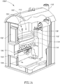
- FIG 1A provides a cutaway view of a heat exchanger 1000 that is consistent with the embodiments disclosed here.
- Heat exchanger 1000 may be a boiler, such as a wood burning boiler.
- Flow arrows in Figure 1A show the flow patterns of air and gasified fuel through heat exchanger 1000.
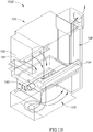
- Figure 1B schematically illustrates, with more detail than that provided by Figure 1A , the flow of air and gasified fuel within the heat exchanger 1000.
- Figure 1B illustrates the structures of the heat exchanger 1000 as transparent structures.
- the fuel is combusted within a burn box, such as burn box 100 of Figure 1B .
- Heat exchanger 1000 includes a door 102 that provides a user access to the interior of a burn box 100. The user may replenish or otherwise provide fuel to the burn box 100, via door 102.
- the fuel may be wood; however, other embodiments are not so constrained.
- Figure 1A shows a burning pile of wood 110 within the burn box 100.
- the woodpile 110 is essentially burning from the bottom up.
- the burning woodpile 110 includes at least three layers: a coal layer 116 at the bottom of the pile 110, a burning layer 114, and a drying layer 112 at the top of the pile 110.
- a primary flow of external air enters the burn box 100 through a plurality of horizontally arranged primary air apertures or inlet ports.
- One of the primary air apertures is indicated with the reference numeral 192.
- the primary apertures that provide the primary airflow are arranged in a horizontal U-shape.
- This primary airflow at least partially provides the oxygen required for the combustion of the woodpile 110.
- the primary airflow entering the burn box 100 from the primary air apertures is shown in Figure 1B through only three of the primary air apertures (including primary air aperture 192). However, it should be understood that the primary airflow is entering the burn box 100 through each of the primary air apertures.
- a secondary airflow is introduced into the bottom portion of the burn box 100.
- the secondary airflow is provided by secondary intake duct 190.
- a plurality of secondary air apertures positioned on a bottom surface of the secondary intake duct 190 introduces the secondary airflow into the bottom portion of the burn box 100.
- One of the secondary air apertures is indicated by the reference numeral 194 in Figure 1B .
- the secondary intake duct 190 (or at least the secondary air apertures) is positioned below the coal layer 116 shown in Figure 1A .
- the primary airflow and the secondary airflow are mixed or otherwise combined.
- the mixture of the primary and secondary airflows include partially gasified and/or combusted fuel.
- the mixture of the primary and secondary airflows flows downward through the aperture 104 in the lower interior surface or floor of the burn box 100 and into a reaction chamber 106 that is positioned vertically below the burn box 100.
- burn box 100 includes a grate, mesh, or filter. Although not shown in Figures 1A-1B , such a grate or mesh ensures that aperture 104 does not become impacted or clogged by ash, coals, charcoal, and other sediments. Such an impaction would prevent the flow of the combination of primary and secondary airflows through aperture 104 and into reaction chamber 106.
- the grate may be positioned vertically above or below the secondary air apertures and above aperture 104. In some embodiments, the grate may at least partially make up the floor of the burn box 100.
- the grate may include small openings to allow the flow of gasified fuel into aperture 104 and into the reaction chamber 106. The fuel combustion process continues within a reaction chamber 106.
- the primary airflow generates a downdraft through the pile 110 and combines with the secondary airflow near the bottom of the burn box 100.
- the secondary airflow provides a flow of oxygen to the gasified fuel that forces the gasified fuel into reaction chamber 106. At least due to the oxygen provided by the secondary airflow, the gasified fuel will continue to react (burn) within the reaction chamber 106 to ensure a more complete burn of the fuel. A more complete burn provides a greater efficiency for heat exchanger 1000.
- the gasified fuel flows through heat exchanger fins 108.
- the heated gas provides thermal energy to water or another thermally conducting liquid within thermal contact with the heat exchanger fins 108.
- a water jacket may be internal or external to the heat exchanger fins 108.
- the heated water in the jacket is directed to another structure, such as a home.
- the flow of the heated water provides the home a portion of the energy released during the combustion of the woodpile 110.
- An exhaust port or chimney 118 directs and carries exhaust from the combustion process away from the heat exchanger 1000.
- the upper portions of the burning layer 114 or the drying layer 112 may form a bridge as the wood underneath these layers combusts. This bridging effect may decrease the efficiency of the heat exchanger 1000.
- the combustion primarily occurs in a lower portion of the burning layer 114 and an upper portion of the coal layer 116. In some conditions, the wood in the upper portion of the burning layer 114 may form a somewhat stable bridge. This bridge inhibits the wood in the upper portion of the burning layer 114 and the drying layer 112 from falling downward to where the combustion is primarily occurring. This bridging effect slows the combustion rate and thus decreases the efficiency of heat exchanger 1000. If the bridging is stable enough, the combustion may be extinguished altogether.
- heat exchanger 1000 includes a system for pushing, shaking, disrupting, agitating, stoking, or otherwise destabilizing the bridging effect in the burning woodpile 110.
- Such an agitating system may include a push member 150.
- a coupler or fastener 160 couples the push member 150, or stoker, to an internal surface of the burn box 100.
- the push member 150 rotates and/or pivots about coupler 160 and towards the woodpile 110. When rotated towards pile 110, push member 150 pushes, disrupts, and/or agitates the burning layer 114 of woodpile 110, and de-stabilizes the bridging effect.
- Such destabilizing of the bridging effect increases the efficiency of the heat exchanger 1000.
- the size and positioning of push member 150 is chosen so that the lower (stoker) portion of the push member 150 engages and interacts with the portion of the woodpile 110 that is prone to bridging, such as the burning layer 114. Agitating woodpile 110 provides the further benefit of insuring that the coal layer 116 does not plug or otherwise obstruct the opening 104 in the floor of the burn box 100, further increasing the efficiency of heat exchanger 1000.
- another push member may be included and coupled to an opposing interior surface of the burn box 100. The other push member may stoke or agitate the pile 110 from the other side.
- the shaking or agitating of the burning pile 110 may be automatically triggered so that any bridging of the wood in the pile 110 is collapsed or destabilized as needed, automatically increasing the efficiency of the heat exchanger 1000.
- the stoking may be triggered periodically based on variable and/or constant time intervals, or in response to inputs, such as the timing of a previous opening of door 102, the timing of a previous agitating sequence, the temperature internal to the burn box 100 or of the water jacket, a gas sensor reading, or the like.
- FIG 2A shows a cutaway perspective view of a burn box 200, which is consistent with various embodiments included in the heat exchanger 1000 of Figure 1A .
- Burn box 200 includes a fuel agitating system.
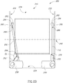
- Figure 2B shows a front view of the burn box 200 of Figure 2A .
- Figure 2C shows a side view of the burn box 200 of Figure 2A .
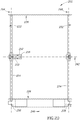
- Figure 2D shows a top view of the burn box 200 of Figure 2A .
- axes such as rotational axes, are represented in Figures 2A-2D by hashed lines with large hashes.
- the wall and/or surfaces of the burn box 200 are transparent to enable a clear view of the interior of burn box 200 and of the agitating system.
- Hashed lines indicate the transparent walls and/or surfaces of burn box 200, where the hashes associated with transparent structures are smaller than the hashes associated with axes.
- burn box 200 includes a front interior or internal surface 226 (as represented by lines with smaller hashes) and a rear interior surface 236.
- a longitudinal axis 246 extends between the front interior surface 226 and the rear interior surface 236 and defines a longitudinal direction of the burn box 200.
- the front and rear interior surfaces 226/236 are opposing surfaces. Although other embodiments need not be so constrained, as shown in the preferred embodiments of Figures 2A-2D , the front and rear interior surfaces 226/236 are parallel surfaces.
- Burn box 200 also includes a lower interior surface 224 and an opposing upper interior surface 234.
- a vertical axis 244 extends between the lower interior surface 224 and the upper interior surface 234 and defines a vertical direction of the burn box 200.
- At least one of the lower or upper interior surfaces 224/234 is substantially orthogonal, or at least transverse to at least one of the front or rear interior surfaces 226/236.
- the vertical axis 244 is substantially orthogonal to the longitudinal axis 246 in some embodiments.
- at least a portion of the lower interior surface 224 is substantially parallel to a portion of the upper interior surface 234.
- burn box 200 includes a left or first lateral or side interior surface 222 and an opposing right or second side interior surface 232.
- a lateral axis 242 extends between the first and second side interior surfaces 222/232 and defines a lateral direction of the burn box 200.
- At least one of the first or second side interior surfaces 222/232 may be orthogonal to at least one of the lower or upper interior surfaces 224/234 and at least one of the front or rear 226/236 interior surfaces.
- the lateral axis 242 is substantially orthogonal to at least one of the vertical axis 244 or the longitudinal axis 246.
- at least a portion of the first side interior surface 222 is substantially parallel to a portion of the second side interior surface 232.
- the sides of the burn box 222 and 232 may be tapered to be wider at the bottom to allow room for the woodpile to shift, move, and settle.
- the top and bottom may be wider than a middle portion of the sides. The narrow portion in the middle keeps the stack somewhat centered while the wider portion at the bottom allows room for efficient burn movement.
- burn box 200 includes an agitating system for agitating or stoking the combusting fuel.
- the agitating system of burn box 200 includes a left or first push member 250 and a right or second push member 270.
- Push members 250/270 push, agitate, disturb, or otherwise stoke the burning layer of fuel within burn box 200, such as the burning layer 114 of burning woodpile 150 of heat exchanger 1000 of Figure 1A .
- Push members 250/270 may include a rod, a bar, an arm, a chain (or chain grid), a cable, a combination of these members, or any other member configured and arranged to stoke or agitate a burning pile of wood within burn box 200.
- push members 250/270 are stoker members.
- Each of the push members 250/270 includes an upper end disposed at the most extreme position of the upper portion of the push member 250/270 and a lower end disposed at the most extreme position of the lower portion of the push member 250/270.
- the lower portions, and specifically the lower ends of the push members 250/270 engage, stoke, and/or disturb the burning layer 114 of the burning pile of wood 150 of Figure 1A .
- the lower ends of the push members 250/270 include a shaped end for agitating wood, such as a poker or pointed end.
- any bridging within the burning layer 114 and the drying layer 112 is de-stabilized to increase the efficiency of the combustion process occurring within burn box 200.
- Burn box 200 includes a left or first coupler 260 and a right or second coupler 280.
- the first coupler 260 pivotally couples the first push member 250 to the first lateral interior surface 222.
- the second coupler 280 pivotally couples the second push member 270 to the second lateral interior surface 232.
- coupler portions of the push members 250/270 are coupled to the upper portions of the lateral side interior surfaces 222/232 respectively.
- the couplers 260/280 are operative to pivotally couple or fastener the push members 250/270 to the respective lateral interior surfaces 222/232 such that the lower portions are vertically below the upper portions of push members 250/270.
- couplers 260/280 are pivotal fasteners.
- the coupler portions 260/280 of the push members 250/270 are vertically between the upper and lower ends of the push members 250/270.
- the upper ends of the push members 250/270 may be pivotally coupled to the interior surfaces 222/232.
- the coupler portions are generally closer to the upper ends than to the lower ends, thus the coupler portions are disposed in the upper portions of the push members 250/270.
- the coupler portion of the first push member 250 includes a first coupler aperture 266.
- the coupler portion of the second push member 270 includes a second coupler aperture 286.
- first coupler 260 includes a first hook 262 and a first loop 264.
- the first hook 262 is rigidly coupled or fastened to the first lateral interior surface 222.
- the first coupler aperture 266 of the first push member 250 receives the first loop 262.
- the first loop 264 is hung over the first hook 262 to pivotally couple the first push member 250 to the first lateral interior surface 222.
- the lower end of the first push member 250 is vertically intermediate the upper end of the first push member 250 and the lower interior surface 224 of burn box 200.
- the first push member 250 When coupled in such a fashion, the first push member 250 may rotate about the first rotational axis 292 (as shown in Figure 2A with a hashed line) towards the second lateral interior surface 232 of burn box 200.
- the first rotational axis 292 is substantially aligned with the first coupling aperture 266 of first push member 250 and is substantially parallel to the longitudinal axis 246 of burn box 200.
- a positive rotation of first push member 250 occurs when first push member 250 is rotating away from first lateral interior surface 222 and towards second lateral interior surface 232.
- a negative rotation of first push member 250 occurs when first push member 250 is rotating away from second lateral interior surface 232 and towards first lateral interior surface 222. Accordingly, terms such as positive-sense rotation and negative-sense rotations may be applied to characterize the direction of the rotation about a given rotational axis.
- Second coupler 280 is similarly constructed as first coupler 260.
- second coupler 280 includes a second hook 282 coupled to the second lateral interior surface 232 and a second loop 284.
- second push member 270 may rotate about a second rotational axis 296 (as shown in Figures 2A and 2C ) and towards the first lateral interior surface 222.
- a positive rotation of second push member 270 occurs when second push member 270 is rotating away from first lateral interior surface 222 and towards second lateral interior surface 232.
- a negative rotation of second push member 270 occurs when second push member 270 is rotating away from second lateral interior surface 232 and towards first lateral interior surface 222. Because the first push member 250 rotates about rotational axis 292 and the second push member 270 rotates about rotational axis 296, rotational axes 292/296 may be push member rotational axes.
- the agitating system of burn box 200 also includes a first driven member 252 and a second driven member 272.
- Driven members 252/272 engage with and provide a rotational inducing torque on first push member 250 and second push member 270 respectively.
- driven members 252/272 may be torque members or engaging members.
- first driven member 252 is configured and arranged to provide a torque on the first push member 250.
- first push member 250 rotates about the first rotational axis 292 in a positive-sense.
- the bottom portion of first push member 250 rotates towards the second lateral interior surface 232 to stoke or agitate the burning layer of a wood pile that is positioned laterally intermediate the first and second lateral interior surfaces 222/232. Note that a component of the force associated with the provided positive torque is directed towards the second lateral interior surface 232.
- second driven member 272 is configured and arranged to provide a torque on the second push member 270.
- second push member 250 rotates about second rotational axis 296 in a negative-sense.
- the bottom portion of second push member 270 rotates towards the first lateral interior surface 222 to stoke or agitate the burning layer of a wood pile that is positioned laterally intermediate the first and second lateral interior surfaces 222/232. Note that a component of the force associated with the provided negative torque is directed towards the first lateral interior surface 222.
- the length of the push members 250/270, as well as the length of the driven members 252/272 may be based on the dimensions of the burn box 200 and the expected positioning and size of the burning pile or stack of fuel within the burn box 200. Preferably, the lengths are chosen such that the lower ends of the push members 250/270 engage with and agitate the burning layer of the fuel stack and destabilizes any bridging effect occurring in the woodpile.
- the driven members 252/272 include a lower portion and an upper portion.
- the upper portions of the driven members 252/272 contacts or engages with contact portions of the push members 250/270, to provide the torque on the push members 250/270.
- the contact portions of push members250/270 are vertically between the coupler portions and the lower ends of the push members 250/270. As discussed further below, such a contact or engagement induces the torque that rotates the push members 250/270 about the rotational axis 292/296 respectively.
- the driven members 252/272 are configured and arranged to rotate about driven member rotational axes 294/298 (as shown in at least Figures 2A and 2D ), respectively.
- Driven member rotational axes 294/298 intersect the lower portions of driven members 252/272 respectively and are each substantially parallel to the push member rotational axes 292/296.
- Driven member rotational axes 294/298 are vertically below the push member rotational axes 292/296.
- the agitating system of burn box 200 includes a first drive member 254 and a second drive member 274.
- First drive member 254 is configured and arranged to drive the rotation of first driven member 252 about driven member rotational axis 294.
- second drive member 274 is configured and arranged to drive the rotation of second driven members 272 about driven member rotational axis 298.
- Drive members 254/274 may be drive rods or drive components and drive the respective driven members 252/272.
- First drive member 254 is configured and arranged to rotate about driven member rotational axis 294.
- second drive member 274 is configured and arranged to rotate about driven member rotational axis 298.
- driven member rotational axes 294/298 may be drive member rotational axes.
- first drive member 254 is rigidly coupled to the first driven member 252.
- second drive member 274 is rigidly coupled to the second driven member 272. Due to this rigid coupling, when the drive members 254/274 are rotated about the respective drive member axes 294/294, the respective driven members 252/272 are co-rotated in the same sense and also by the same angular displacement. Accordingly, when the first drive member 254 is rotated in a negative-sense, the first driven member 252 is co-rotated to engage with and provide torque to the first push member 250. A negative rotation of the first drive member 254 drives the positive rotation of the first push member 250 about push member rotational axis 292.
- a positive rotation of second drive member 274 drives a negative rotation of the second push member 270 about the push member rotational axis 296.
- Drive members 254/274 may extend beyond the exterior of the burn box 200 such that the drive members 254/274 (as well as the driven members 252/272 and the push members 250/270) are rotatable from the exterior region of burn box 200.
- the driven members 252/272 are operative to return the push member 250/270 to the lateral interior surfaces 222/232 respectively. This feature enables multiple successive agitations of the woodpile and insures the push members 250/270 do not become lodged or stuck within the burn wood. Other embodiments are not so constrained, and may rely on gravity alone to return push members 250/270 to a substantially vertical orientation.
- each of driven members 252/272 includes an upper surface.
- a first upper receiving aperture 256 is positioned in the upper surface of first driven member 252.
- the first receiving aperture 256 is configured and arranged to slidably receive the lower end or lower portion of first push member 250.
- the driven member 252 rotates about driven member rotational axis 294
- the first push member co-rotates about push member axis 292, as well as slides along first receiving aperture 256 of the first driven member 252.
- the surfaces of first receiving aperture 256 engage with the first push member 250. This engagement enables first driven member 252 to provide both positive and negative torques to first push member 250.
- first drive member 252 is operative (via negative rotation about rotational axis 294) to rotate first push member 250 towards second lateral interior surface 232 (positive rotation) and (via positive rotation about rotational axis 294) back towards the first lateral interior surface 222 (negative rotation).
- First drive member 254 is configured and arranged to return first push member 250 back to a substantially vertical orientation. Accordingly, first drive member 254 is operative to both "push” (towards second lateral interior surface 232) and “pull” (away from second lateral interior surface 232) first push member 250.
- Other embodiments may be operative to only "push” on push members 250/270 and rely on gravity to assist with returning the push members 250/270 to the initial vertical position.
- second driven member 272 includes a second receiving aperture 276.
- first drive member 252 is operative (via positive rotation about rotational axis 298) to rotate second push member 270 both towards first lateral interior surface 222 (negative rotation) and (via negative rotation about rotational axis 298) back towards the second lateral interior surface 232 (positive rotation).
- FIG. 2B shows angle ⁇ between first push member 250 and first driven member 252.
- angle ⁇ is within a plane that is substantially orthogonal to the rotational axes 292/296.
- the lateral width of at least one of the receiving apertures 256/276 is large enough to slidable receive the corresponding push members 250/270, so that the angle ⁇ between the push members 250/270 and corresponding driven members 252/272 varies between at least 130 and 180 degrees.
- the lateral width of the receiving apertures 256/276 may be varied to accommodate other ranges of the variable angle between push members 250/270 and corresponding driven members 252/272.
- the agitating system of burn box 200 further includes a first actuator 258 and a second actuator 278.
- First actuator 258 is operative to rotate first push member 250.
- second actuator 278 is operative to rotate second push member 270.
- first actuator 258 is operative to rotate first drive member 254, about drive member rotational axis 294, to drive the rotation of first push member 250 about the push member rotational axes 292.
- second actuator 278 is operative to rotate second drive member 274, about drive member rotational axis 298, to drive the rotation of second push member 270 about the push member rotational axes 296.
- Actuators 258/278 may provide both positive and negative torque so that the push members 250/270 are both “pushed” and “pulled” when stoking a woodpile.
- the actuators 258/278 may be electro-mechanical actuators.
- the actuators 258/278 may include motors.
- actuators 258/278 may automatically rotate push members 250/270 to automatically stoke the woodpile within burn box 200.
- actuators 258/278 are positioned external to the burn box 200 to protect the actuators 258/278 from the thermal energy within burn box 200.
- the actuators 258/278 may be coupled to portions of drive members 254/274 that are external to burn box 200.
- components of the actuators 258/278 may be housed within heat or fire resistant housings to protect heat sensitive components.
- Actuators 258/278 may include one or more processor devices, networking devices, memory devices, timer devices, or sensing devices. Such devices may enable a remote control and/or autonomous operation of the agitating system
- the system may be automatically triggered via one or more triggering events.
- triggering events may be indicative of a situation where initiating or terminating an ongoing agitation sequence is beneficial regarding the operation or safety associated with the operation of the heat exchanger.
- triggering events include, but are not limited to closing the access door 202 to the burn box 200, an excessive load on the actuators 258/278, or a dramatic increase/decrease of the rate of combustion or temperature within burn box 200.
- Various sensors may be included in the agitating system to detect one or more of possible triggering events. When a triggering event is detected, depending upon the current operation of the system and the nature of the detected event, the agitating system may either initiate an agitating sequence, or terminate an ongoing sequence.
- an alert may be provided to a user.
- the alert may be an audible alert and/or a visual alert.
- the alert may be provided to a mobile user device, such as a smartphone, tablet, or other networked computing device via a network device included in the system.
- the alert may include data regarding the nature of the triggering event, as well as a time, date, and/or geo-stamp.
- the actuators 258/278 may include torque or load sensors. When a torque sensor senses a torque or load greater than the load rating of a motor within the actuator, the motor may shut down. In the event that the woodpile becomes lodged or one of the push members 250/270 become ensnared in a particular stable bridge formed in the woodpile, such torque sensors prevent damage to the actuators 258/278. An alert may be provided to the user to indicate to the user that a manual stoking of the combustion may be required to dislodge the stuck push member 250/270. The actuators 258/278 may then automatically or manually be reset.
- triggering events may include the closing of the door 202, such as when a user re-supplies wood for the combustion process.
- the agitating system of burn box 200 may include a door sensor that generates a signal is transitioned from an open state to a closed state.
- a signal generated from closing the door may initiate an agitation sequence. For instance, after adding wood to the fire, the woodpile may be agitated on regular intervals. Accordingly, after sensing a closing of the door 202, the agitating system may agitate the woodpile, every two hours, or any other constant or variable timing sequence.
- the time sequence is programmable by a user.
- the agitating sequence may be a lateral alternating sequence in time.
- actuators 259/278 may be operative to rotate the push members 250/270 sequentially in an alternating sequence. While first push member 250 is being rotated towards second interior surface 232, second push member 270 is not being rotated towards second interior surface 232 so that push members 250/270 are not simultaneously push on the wood in opposite directions. Such an operation may put the pile of wood under compression and may decrease the efficiency of stoking of the woodpile.
- the agitation system includes at least one of an oxygen sensor, a carbon monoxide sensor, or a temperature sensor that is enabled to sense conditions within the burn box 200.
- the agitation system may initiate or terminate an agitating sequence based on signals generated by at least one of these sensors.
- a wireless transceiver device such as a WIFI or a BLUETOOTH transmitter, may be included in the agitation system.
- Such a wireless transceiver is operative to receive a wireless signal generated by a remote or mobile device, such as a smartphone or tablet. Accordingly, the agitation system may be remotely operated and/or programmed.
Landscapes
- Engineering & Computer Science (AREA)
- Chemical & Material Sciences (AREA)
- Combustion & Propulsion (AREA)
- Mechanical Engineering (AREA)
- General Engineering & Computer Science (AREA)
- Physics & Mathematics (AREA)
- Thermal Sciences (AREA)
- Mixers Of The Rotary Stirring Type (AREA)
- Solid-Fuel Combustion (AREA)
Description
- The present disclosure relates to a system for agitating fuel within a heat exchanger and, more particularly, to a system for automatically agitating a burning woodpile within a boiler.
- Heat exchangers selectively transfer thermal energy from a thermal source to a thermal destination. One example of a heat exchanger is a boiler. The combustion of fuel (the thermal source) within the boiler releases thermal energy. A thermally conducting fluid or gas, such as water, captures the released thermal energy, via a heat exchange process. Plumbing or ducts selectively channel and/or deliver the heated water from the boiler, to another structure, such as a home (the thermal destination). At the home, the released thermal energy is at least partially extracted from the flowing water and used for other purposes, such as heating the home.
- Various boilers use wood as the combustible fuel. Such boilers may include a burn box that houses a pile of burning wood. The burning of the wood releases the thermal energy that is ultimately delivered to the home. As wood is added to the woodpile or as the wood burns, periodically stoking and/or agitating the woodpile increases the efficiency of the burn and thus the overall efficiency of the boiler. It is for these and other concerns that the following disclosure is provided.
-
US 2008 156237 A1 discloses a combustor for solid particulate fuels including a rotary agitator extending across the combustor chamber with the agitator having a plurality of radial arms. - According to the invention there is disclosed a burn box according to claim 1. Further developments of the invention can be taken from the dependent claims.
- Preferred and alternative examples of the present invention are described in detail below with reference to the following drawings:
-
Figure 1A provides a cutaway view of a heat exchanger that is consistent with the embodiments disclosed here. -
Figure 1B schematically illustrates a flow of air and gasified fuel within the heat exchanger ofFigure 1A . -
Figure 2A shows a cutaway perspective view of a burn box, which is consistent with various embodiments included in the heat exchanger ofFigure 1A . -
Figure 2B shows a front view of the burn box ofFigure 2A . -
Figure 2C shows a side view of the burn box ofFigure 2A . -
Figure 2D shows a top view of the burn box ofFigure 2A . - To facilitate the understanding of this invention, a number of terms are defined below. Terms defined herein have meanings as commonly understood by a person of ordinary skill in the areas relevant to the present invention. Terms such as "a," "an," and "the" are not intended to refer to only a singular entity, but include the general class of which a specific example may be used for illustration. The terminology herein is used to describe specific embodiments of the invention, but their usage does not delimit the invention, except as outlined in the claims.
-
Figure 1A provides a cutaway view of aheat exchanger 1000 that is consistent with the embodiments disclosed here.Heat exchanger 1000 may be a boiler, such as a wood burning boiler. Flow arrows inFigure 1A show the flow patterns of air and gasified fuel throughheat exchanger 1000.Figure 1B schematically illustrates, with more detail than that provided byFigure 1A , the flow of air and gasified fuel within theheat exchanger 1000. To demonstrate the details of the airflow internal to theheat exchanger 1000,Figure 1B illustrates the structures of theheat exchanger 1000 as transparent structures. The fuel is combusted within a burn box, such asburn box 100 ofFigure 1B .Heat exchanger 1000 includes adoor 102 that provides a user access to the interior of aburn box 100. The user may replenish or otherwise provide fuel to theburn box 100, viadoor 102. - In preferred embodiments, the fuel may be wood; however, other embodiments are not so constrained.
Figure 1A shows a burning pile ofwood 110 within theburn box 100. Thewoodpile 110 is essentially burning from the bottom up. Theburning woodpile 110 includes at least three layers: acoal layer 116 at the bottom of thepile 110, a burninglayer 114, and adrying layer 112 at the top of thepile 110. As shown by the flow arrows inFigure 1B , a primary flow of external air enters theburn box 100 through a plurality of horizontally arranged primary air apertures or inlet ports. One of the primary air apertures is indicated with thereference numeral 192. In some embodiments, the primary apertures that provide the primary airflow are arranged in a horizontal U-shape. This primary airflow at least partially provides the oxygen required for the combustion of thewoodpile 110. For purposes of clarity, the primary airflow entering theburn box 100 from the primary air apertures is shown inFigure 1B through only three of the primary air apertures (including primary air aperture 192). However, it should be understood that the primary airflow is entering theburn box 100 through each of the primary air apertures. - As also shown by the flow arrows of
Figures 1A-1B , a secondary airflow is introduced into the bottom portion of theburn box 100. The secondary airflow is provided bysecondary intake duct 190. A plurality of secondary air apertures positioned on a bottom surface of thesecondary intake duct 190 introduces the secondary airflow into the bottom portion of theburn box 100. One of the secondary air apertures is indicated by thereference numeral 194 inFigure 1B . In various embodiments, the secondary intake duct 190 (or at least the secondary air apertures) is positioned below thecoal layer 116 shown inFigure 1A . - In the bottom portion of the
burn box 100, the primary airflow and the secondary airflow are mixed or otherwise combined. Near the bottom of theburn box 100, the mixture of the primary and secondary airflows include partially gasified and/or combusted fuel. The mixture of the primary and secondary airflows flows downward through theaperture 104 in the lower interior surface or floor of theburn box 100 and into areaction chamber 106 that is positioned vertically below theburn box 100. - In some embodiments,
burn box 100 includes a grate, mesh, or filter. Although not shown inFigures 1A-1B , such a grate or mesh ensures thataperture 104 does not become impacted or clogged by ash, coals, charcoal, and other sediments. Such an impaction would prevent the flow of the combination of primary and secondary airflows throughaperture 104 and intoreaction chamber 106. The grate may be positioned vertically above or below the secondary air apertures and aboveaperture 104. In some embodiments, the grate may at least partially make up the floor of theburn box 100. The grate may include small openings to allow the flow of gasified fuel intoaperture 104 and into thereaction chamber 106. The fuel combustion process continues within areaction chamber 106. - As shown in detail in
Figures 1A-1B , the primary airflow generates a downdraft through thepile 110 and combines with the secondary airflow near the bottom of theburn box 100. The secondary airflow provides a flow of oxygen to the gasified fuel that forces the gasified fuel intoreaction chamber 106. At least due to the oxygen provided by the secondary airflow, the gasified fuel will continue to react (burn) within thereaction chamber 106 to ensure a more complete burn of the fuel. A more complete burn provides a greater efficiency forheat exchanger 1000. - Upon continued reaction with the
reaction chamber 106, the gasified fuel flows throughheat exchanger fins 108. The heated gas provides thermal energy to water or another thermally conducting liquid within thermal contact with theheat exchanger fins 108. For instance, a water jacket may be internal or external to theheat exchanger fins 108. The heated water in the jacket is directed to another structure, such as a home. The flow of the heated water provides the home a portion of the energy released during the combustion of thewoodpile 110. An exhaust port orchimney 118 directs and carries exhaust from the combustion process away from theheat exchanger 1000. - When a
woodpile 110 burns from the bottom up, with a downdraft and/or downward gas effluent flow as shown inFigure 1B , the upper portions of the burninglayer 114 or thedrying layer 112 may form a bridge as the wood underneath these layers combusts. This bridging effect may decrease the efficiency of theheat exchanger 1000. The combustion primarily occurs in a lower portion of the burninglayer 114 and an upper portion of thecoal layer 116. In some conditions, the wood in the upper portion of the burninglayer 114 may form a somewhat stable bridge. This bridge inhibits the wood in the upper portion of the burninglayer 114 and thedrying layer 112 from falling downward to where the combustion is primarily occurring. This bridging effect slows the combustion rate and thus decreases the efficiency ofheat exchanger 1000. If the bridging is stable enough, the combustion may be extinguished altogether. - Accordingly,
heat exchanger 1000 includes a system for pushing, shaking, disrupting, agitating, stoking, or otherwise destabilizing the bridging effect in the burningwoodpile 110. Such an agitating system may include apush member 150. A coupler orfastener 160 couples thepush member 150, or stoker, to an internal surface of theburn box 100. Thepush member 150 rotates and/or pivots aboutcoupler 160 and towards thewoodpile 110. When rotated towardspile 110,push member 150 pushes, disrupts, and/or agitates the burninglayer 114 ofwoodpile 110, and de-stabilizes the bridging effect. Such destabilizing of the bridging effect increases the efficiency of theheat exchanger 1000. - In preferred embodiments, the size and positioning of
push member 150 is chosen so that the lower (stoker) portion of thepush member 150 engages and interacts with the portion of thewoodpile 110 that is prone to bridging, such as the burninglayer 114. Agitatingwoodpile 110 provides the further benefit of insuring that thecoal layer 116 does not plug or otherwise obstruct theopening 104 in the floor of theburn box 100, further increasing the efficiency ofheat exchanger 1000. Although not shown inFigure 1A , another push member may be included and coupled to an opposing interior surface of theburn box 100. The other push member may stoke or agitate thepile 110 from the other side. - As discussed further below, the shaking or agitating of the burning
pile 110 may be automatically triggered so that any bridging of the wood in thepile 110 is collapsed or destabilized as needed, automatically increasing the efficiency of theheat exchanger 1000. The stoking may be triggered periodically based on variable and/or constant time intervals, or in response to inputs, such as the timing of a previous opening ofdoor 102, the timing of a previous agitating sequence, the temperature internal to theburn box 100 or of the water jacket, a gas sensor reading, or the like. -
Figure 2A shows a cutaway perspective view of aburn box 200, which is consistent with various embodiments included in theheat exchanger 1000 ofFigure 1A .Burn box 200 includes a fuel agitating system.Figure 2B shows a front view of theburn box 200 ofFigure 2A .Figure 2C shows a side view of theburn box 200 ofFigure 2A .Figure 2D shows a top view of theburn box 200 ofFigure 2A . As discussed herein, axes, such as rotational axes, are represented inFigures 2A-2D by hashed lines with large hashes. - Note that in
Figures 2B-2D , the wall and/or surfaces of theburn box 200 are transparent to enable a clear view of the interior ofburn box 200 and of the agitating system. Hashed lines indicate the transparent walls and/or surfaces ofburn box 200, where the hashes associated with transparent structures are smaller than the hashes associated with axes. - In various embodiments,
burn box 200 includes a front interior or internal surface 226 (as represented by lines with smaller hashes) and a rearinterior surface 236. A longitudinal axis 246 (as represented by lines with larger hashes) extends between the frontinterior surface 226 and the rearinterior surface 236 and defines a longitudinal direction of theburn box 200. The front and rearinterior surfaces 226/236 are opposing surfaces. Although other embodiments need not be so constrained, as shown in the preferred embodiments ofFigures 2A-2D , the front and rearinterior surfaces 226/236 are parallel surfaces. -
Burn box 200 also includes a lowerinterior surface 224 and an opposing upperinterior surface 234. Avertical axis 244 extends between the lowerinterior surface 224 and the upperinterior surface 234 and defines a vertical direction of theburn box 200. At least one of the lower or upperinterior surfaces 224/234 is substantially orthogonal, or at least transverse to at least one of the front or rearinterior surfaces 226/236. Thus, thevertical axis 244 is substantially orthogonal to thelongitudinal axis 246 in some embodiments. In some embodiments, at least a portion of the lowerinterior surface 224 is substantially parallel to a portion of the upperinterior surface 234. - In preferred embodiments,
burn box 200 includes a left or first lateral or sideinterior surface 222 and an opposing right or second sideinterior surface 232. Alateral axis 242 extends between the first and second sideinterior surfaces 222/232 and defines a lateral direction of theburn box 200. At least one of the first or second sideinterior surfaces 222/232 may be orthogonal to at least one of the lower or upperinterior surfaces 224/234 and at least one of the front or rear 226/236 interior surfaces. Thelateral axis 242 is substantially orthogonal to at least one of thevertical axis 244 or thelongitudinal axis 246. In some embodiments, at least a portion of the first sideinterior surface 222 is substantially parallel to a portion of the second sideinterior surface 232. In alternate embodiments the sides of theburn box - As discussed above,
burn box 200 includes an agitating system for agitating or stoking the combusting fuel. The agitating system ofburn box 200 includes a left orfirst push member 250 and a right orsecond push member 270. Pushmembers 250/270 push, agitate, disturb, or otherwise stoke the burning layer of fuel withinburn box 200, such as the burninglayer 114 of burningwoodpile 150 ofheat exchanger 1000 ofFigure 1A . Pushmembers 250/270 may include a rod, a bar, an arm, a chain (or chain grid), a cable, a combination of these members, or any other member configured and arranged to stoke or agitate a burning pile of wood withinburn box 200. According to the invention, pushmembers 250/270 are stoker members. - Each of the
push members 250/270 includes an upper end disposed at the most extreme position of the upper portion of thepush member 250/270 and a lower end disposed at the most extreme position of the lower portion of thepush member 250/270. When activated or driven, the lower portions, and specifically the lower ends of thepush members 250/270 engage, stoke, and/or disturb the burninglayer 114 of the burning pile ofwood 150 ofFigure 1A . In some embodiments, the lower ends of thepush members 250/270 include a shaped end for agitating wood, such as a poker or pointed end. As discussed above, when the burninglayer 114 is agitated, any bridging within the burninglayer 114 and thedrying layer 112 is de-stabilized to increase the efficiency of the combustion process occurring withinburn box 200. -
Burn box 200 includes a left orfirst coupler 260 and a right orsecond coupler 280. Thefirst coupler 260 pivotally couples thefirst push member 250 to the first lateralinterior surface 222. Likewise, thesecond coupler 280 pivotally couples thesecond push member 270 to the second lateralinterior surface 232. As shown in the preferred embodiments, coupler portions of thepush members 250/270 are coupled to the upper portions of the lateral sideinterior surfaces 222/232 respectively. Thus, thecouplers 260/280 are operative to pivotally couple or fastener thepush members 250/270 to the respective lateralinterior surfaces 222/232 such that the lower portions are vertically below the upper portions ofpush members 250/270. In various embodiments,couplers 260/280 are pivotal fasteners. - As shown in
Figures 2A-2D , thecoupler portions 260/280 of thepush members 250/270 are vertically between the upper and lower ends of thepush members 250/270. Although other embodiments are not so constrained, the upper ends of thepush members 250/270 may be pivotally coupled to theinterior surfaces 222/232. The coupler portions are generally closer to the upper ends than to the lower ends, thus the coupler portions are disposed in the upper portions of thepush members 250/270. As shown in at leastFigure 2B , in some embodiments, the coupler portion of thefirst push member 250 includes afirst coupler aperture 266. Likewise, the coupler portion of thesecond push member 270 includes asecond coupler aperture 286. - In some embodiments,
first coupler 260 includes afirst hook 262 and afirst loop 264. Thefirst hook 262 is rigidly coupled or fastened to the first lateralinterior surface 222. Thefirst coupler aperture 266 of thefirst push member 250 receives thefirst loop 262. Thefirst loop 264 is hung over thefirst hook 262 to pivotally couple thefirst push member 250 to the first lateralinterior surface 222. When hung as shown inFigure 2B , the lower end of thefirst push member 250 is vertically intermediate the upper end of thefirst push member 250 and the lowerinterior surface 224 ofburn box 200. When coupled in such a fashion, thefirst push member 250 may rotate about the first rotational axis 292 (as shown inFigure 2A with a hashed line) towards the second lateralinterior surface 232 ofburn box 200. In various embodiments, the firstrotational axis 292 is substantially aligned with thefirst coupling aperture 266 offirst push member 250 and is substantially parallel to thelongitudinal axis 246 ofburn box 200. - As used herein, when discussing rotational vectors and rotation in general, a right-handed rotational convention is adopted. For instance, when discussing a rotation about an axis that is substantially parallel to the
longitudinal axis 246, such as aboutrotational axis 292, the positive rotational vector points along the axis and in a direction that is from the rearinterior surface 236 to the frontinternal surface 226. Thus, as shown inFigure 2B , a positive rotation offirst push member 250 occurs whenfirst push member 250 is rotating away from first lateralinterior surface 222 and towards second lateralinterior surface 232. A negative rotation offirst push member 250 occurs whenfirst push member 250 is rotating away from second lateralinterior surface 232 and towards first lateralinterior surface 222. Accordingly, terms such as positive-sense rotation and negative-sense rotations may be applied to characterize the direction of the rotation about a given rotational axis. -
Second coupler 280 is similarly constructed asfirst coupler 260. For example,second coupler 280 includes asecond hook 282 coupled to the second lateralinterior surface 232 and asecond loop 284. When similarly coupled tosecond hook 282 viasecond loop 232,second push member 270 may rotate about a second rotational axis 296 (as shown inFigures 2A and2C ) and towards the first lateralinterior surface 222. - A positive rotation of
second push member 270 occurs whensecond push member 270 is rotating away from first lateralinterior surface 222 and towards second lateralinterior surface 232. A negative rotation ofsecond push member 270 occurs whensecond push member 270 is rotating away from second lateralinterior surface 232 and towards first lateralinterior surface 222. Because thefirst push member 250 rotates aboutrotational axis 292 and thesecond push member 270 rotates aboutrotational axis 296,rotational axes 292/296 may be push member rotational axes. - The agitating system of
burn box 200 also includes a first drivenmember 252 and a second drivenmember 272. Drivenmembers 252/272 engage with and provide a rotational inducing torque onfirst push member 250 andsecond push member 270 respectively. Accordingly, drivenmembers 252/272 may be torque members or engaging members. - For instance, as shown in
Figures 2A-2B and2D , first drivenmember 252 is configured and arranged to provide a torque on thefirst push member 250. When the torque provided by the first drivenmember 252 is a positive torque,first push member 250 rotates about the firstrotational axis 292 in a positive-sense. The bottom portion offirst push member 250 rotates towards the second lateralinterior surface 232 to stoke or agitate the burning layer of a wood pile that is positioned laterally intermediate the first and second lateralinterior surfaces 222/232. Note that a component of the force associated with the provided positive torque is directed towards the second lateralinterior surface 232. - Similarly, second driven
member 272 is configured and arranged to provide a torque on thesecond push member 270. When the torque provided by the second drivenmember 272 is a negative torque,second push member 250 rotates about secondrotational axis 296 in a negative-sense. The bottom portion ofsecond push member 270 rotates towards the first lateralinterior surface 222 to stoke or agitate the burning layer of a wood pile that is positioned laterally intermediate the first and second lateralinterior surfaces 222/232. Note that a component of the force associated with the provided negative torque is directed towards the first lateralinterior surface 222. - The length of the
push members 250/270, as well as the length of the drivenmembers 252/272 may be based on the dimensions of theburn box 200 and the expected positioning and size of the burning pile or stack of fuel within theburn box 200. Preferably, the lengths are chosen such that the lower ends of thepush members 250/270 engage with and agitate the burning layer of the fuel stack and destabilizes any bridging effect occurring in the woodpile. - In various embodiments, the driven
members 252/272 include a lower portion and an upper portion. The upper portions of the drivenmembers 252/272 contacts or engages with contact portions of thepush members 250/270, to provide the torque on thepush members 250/270. The contact portions of push members250/270 are vertically between the coupler portions and the lower ends of thepush members 250/270. As discussed further below, such a contact or engagement induces the torque that rotates thepush members 250/270 about therotational axis 292/296 respectively. - As shown in at least
Figure 2A , in order to provide the torque on thepush members 250/260, the drivenmembers 252/272 are configured and arranged to rotate about driven memberrotational axes 294/298 (as shown in at leastFigures 2A and2D ), respectively. Driven memberrotational axes 294/298 intersect the lower portions of drivenmembers 252/272 respectively and are each substantially parallel to the push memberrotational axes 292/296. Driven memberrotational axes 294/298 are vertically below the push memberrotational axes 292/296. When the first drivenmember 252 rotates, in a negative-sense, about driven memberrotational axis 294,first push member 250 rotates in a positive-sense about push memberrotational axis 292. - In preferred embodiments, the agitating system of
burn box 200 includes afirst drive member 254 and asecond drive member 274.First drive member 254 is configured and arranged to drive the rotation of first drivenmember 252 about driven memberrotational axis 294. Likewise,second drive member 274 is configured and arranged to drive the rotation of second drivenmembers 272 about driven memberrotational axis 298. -
Drive members 254/274 may be drive rods or drive components and drive the respective drivenmembers 252/272.First drive member 254 is configured and arranged to rotate about driven memberrotational axis 294. Likewise,second drive member 274 is configured and arranged to rotate about driven memberrotational axis 298. Accordingly, driven memberrotational axes 294/298 may be drive member rotational axes. - In order to drive the rotation,
first drive member 254 is rigidly coupled to the first drivenmember 252. Likewise, thesecond drive member 274 is rigidly coupled to the second drivenmember 272. Due to this rigid coupling, when thedrive members 254/274 are rotated about the respective drive member axes 294/294, the respective drivenmembers 252/272 are co-rotated in the same sense and also by the same angular displacement. Accordingly, when thefirst drive member 254 is rotated in a negative-sense, the first drivenmember 252 is co-rotated to engage with and provide torque to thefirst push member 250. A negative rotation of thefirst drive member 254 drives the positive rotation of thefirst push member 250 about push memberrotational axis 292. Likewise, a positive rotation ofsecond drive member 274 drives a negative rotation of thesecond push member 270 about the push memberrotational axis 296.Drive members 254/274 may extend beyond the exterior of theburn box 200 such that thedrive members 254/274 (as well as the drivenmembers 252/272 and thepush members 250/270) are rotatable from the exterior region ofburn box 200. - In preferred embodiments, the driven
members 252/272 are operative to return thepush member 250/270 to the lateralinterior surfaces 222/232 respectively. This feature enables multiple successive agitations of the woodpile and insures thepush members 250/270 do not become lodged or stuck within the burn wood. Other embodiments are not so constrained, and may rely on gravity alone to returnpush members 250/270 to a substantially vertical orientation. - As shown in at least
Figure 2A , each of drivenmembers 252/272 includes an upper surface. A firstupper receiving aperture 256 is positioned in the upper surface of first drivenmember 252. Thefirst receiving aperture 256 is configured and arranged to slidably receive the lower end or lower portion offirst push member 250. When the drivenmember 252 rotates about driven memberrotational axis 294, the first push member co-rotates aboutpush member axis 292, as well as slides along first receivingaperture 256 of the first drivenmember 252. The surfaces of first receivingaperture 256 engage with thefirst push member 250. This engagement enables first drivenmember 252 to provide both positive and negative torques tofirst push member 250. Accordingly,first drive member 252 is operative (via negative rotation about rotational axis 294) to rotatefirst push member 250 towards second lateral interior surface 232 (positive rotation) and (via positive rotation about rotational axis 294) back towards the first lateral interior surface 222 (negative rotation).First drive member 254 is configured and arranged to returnfirst push member 250 back to a substantially vertical orientation. Accordingly,first drive member 254 is operative to both "push" (towards second lateral interior surface 232) and "pull" (away from second lateral interior surface 232)first push member 250. Other embodiments may be operative to only "push" onpush members 250/270 and rely on gravity to assist with returning thepush members 250/270 to the initial vertical position. - Similarly, second driven
member 272 includes asecond receiving aperture 276. Thus,first drive member 252 is operative (via positive rotation about rotational axis 298) to rotatesecond push member 270 both towards first lateral interior surface 222 (negative rotation) and (via negative rotation about rotational axis 298) back towards the second lateral interior surface 232 (positive rotation). - As driven
members 252/272 and pushmembers 250/270 co-rotate, the angle between the driven and push member pairs varies. For instance,Figure 2B shows angle α betweenfirst push member 250 and first drivenmember 252. Note that angle α is within a plane that is substantially orthogonal to therotational axes 292/296. In various embodiments, the lateral width of at least one of the receivingapertures 256/276 is large enough to slidable receive thecorresponding push members 250/270, so that the angle α between thepush members 250/270 and corresponding drivenmembers 252/272 varies between at least 130 and 180 degrees. In other embodiments, the lateral width of the receivingapertures 256/276 may be varied to accommodate other ranges of the variable angle betweenpush members 250/270 and corresponding drivenmembers 252/272. - In some embodiments, the agitating system of
burn box 200 further includes afirst actuator 258 and asecond actuator 278.First actuator 258 is operative to rotatefirst push member 250. Likewise,second actuator 278 is operative to rotatesecond push member 270. In preferred embodiments,first actuator 258 is operative to rotatefirst drive member 254, about drive memberrotational axis 294, to drive the rotation offirst push member 250 about the push member rotational axes 292. Similarly,second actuator 278 is operative to rotatesecond drive member 274, about drive memberrotational axis 298, to drive the rotation ofsecond push member 270 about the push member rotational axes 296. -
Actuators 258/278 may provide both positive and negative torque so that thepush members 250/270 are both "pushed" and "pulled" when stoking a woodpile. Theactuators 258/278 may be electro-mechanical actuators. For instance, theactuators 258/278 may include motors. In some embodiments,actuators 258/278 may automatically rotatepush members 250/270 to automatically stoke the woodpile withinburn box 200. - In the embodiments shown in
Figures 2A-2D ,actuators 258/278 are positioned external to theburn box 200 to protect theactuators 258/278 from the thermal energy withinburn box 200. In such embodiments, theactuators 258/278 may be coupled to portions ofdrive members 254/274 that are external to burnbox 200. In at least one embodiments, components of theactuators 258/278 may be housed within heat or fire resistant housings to protect heat sensitive components.Actuators 258/278 may include one or more processor devices, networking devices, memory devices, timer devices, or sensing devices. Such devices may enable a remote control and/or autonomous operation of the agitating system - In various embodiments of an autonomous agitating system, the system may be automatically triggered via one or more triggering events. Such triggering events may be indicative of a situation where initiating or terminating an ongoing agitation sequence is beneficial regarding the operation or safety associated with the operation of the heat exchanger. Such triggering events include, but are not limited to closing the
access door 202 to theburn box 200, an excessive load on theactuators 258/278, or a dramatic increase/decrease of the rate of combustion or temperature withinburn box 200. - Various sensors may be included in the agitating system to detect one or more of possible triggering events. When a triggering event is detected, depending upon the current operation of the system and the nature of the detected event, the agitating system may either initiate an agitating sequence, or terminate an ongoing sequence. In response to a triggering event, an alert may be provided to a user. The alert may be an audible alert and/or a visual alert. The alert may be provided to a mobile user device, such as a smartphone, tablet, or other networked computing device via a network device included in the system. The alert may include data regarding the nature of the triggering event, as well as a time, date, and/or geo-stamp.
- For instance, the
actuators 258/278 may include torque or load sensors. When a torque sensor senses a torque or load greater than the load rating of a motor within the actuator, the motor may shut down. In the event that the woodpile becomes lodged or one of thepush members 250/270 become ensnared in a particular stable bridge formed in the woodpile, such torque sensors prevent damage to theactuators 258/278. An alert may be provided to the user to indicate to the user that a manual stoking of the combustion may be required to dislodge thestuck push member 250/270. Theactuators 258/278 may then automatically or manually be reset. - Other triggering events may include the closing of the
door 202, such as when a user re-supplies wood for the combustion process. The agitating system ofburn box 200 may include a door sensor that generates a signal is transitioned from an open state to a closed state. A signal generated from closing the door may initiate an agitation sequence. For instance, after adding wood to the fire, the woodpile may be agitated on regular intervals. Accordingly, after sensing a closing of thedoor 202, the agitating system may agitate the woodpile, every two hours, or any other constant or variable timing sequence. In at least one embodiment, the time sequence is programmable by a user. - The agitating sequence may be a lateral alternating sequence in time. For instance, actuators 259/278 may be operative to rotate the
push members 250/270 sequentially in an alternating sequence. Whilefirst push member 250 is being rotated towards secondinterior surface 232,second push member 270 is not being rotated towards secondinterior surface 232 so thatpush members 250/270 are not simultaneously push on the wood in opposite directions. Such an operation may put the pile of wood under compression and may decrease the efficiency of stoking of the woodpile. - In at least one unclaimed embodiment, the agitation system includes at least one of an oxygen sensor, a carbon monoxide sensor, or a temperature sensor that is enabled to sense conditions within the
burn box 200. The agitation system may initiate or terminate an agitating sequence based on signals generated by at least one of these sensors. Furthermore, a wireless transceiver device, such as a WIFI or a BLUETOOTH transmitter, may be included in the agitation system. Such a wireless transceiver is operative to receive a wireless signal generated by a remote or mobile device, such as a smartphone or tablet. Accordingly, the agitation system may be remotely operated and/or programmed.
Claims (15)
- A burn box that houses burning wood, the burn box (200) comprising:a first interior surface (222);a second interior surface (232) that opposes the first interior surface (222);a first stoker member (250) that includes a first stoker portion, wherein the first stoker portion is positioned closer to the first interior surface (222) than to the second interior surface (232) such that the burning wood is positioned intermediate the first stoker portion and the second interior surface (232);wherein the first stoker member (250) is configured and arranged to be driven such that the first stoker portion moves towards the second interior surface (232) to agitate the burning wood; anda first driven member (252) that engages the first stoker member (250), wherein - when the first driven member (252) is driven - the first driven member (252) and the first stoker member (250) co-rotate in opposing directions.
- The box of claim 1, wherein the first driven member (252) engages the first stoker member (250) such that - when the first driven member (252) is driven in a first direction - the first driven member (252) applies a first force on the first stoker member (250), and wherein the first force is at least partially directed toward the second interior surface (232) so that the first stoker portion moves toward the second interior surface (232).
- The box of claim 2, wherein - when driven in a second direction - the first driven member (252) applies a second force on the first stoker member (250) that is at least partially directed toward the first interior surface (222) so that the first stoker portion moves toward the first interior surface (222).
- The box of claim 2, wherein - when the first driven member (252) is driven in the first direction - the first driven member (252) and the first stoker member (250) co-rotate in opposing directions such that a first angle between the first driven member (252) and the first stoker portion is varied.
- The box of claim 1, further comprising:
a first actuator (258) that is operative to drive the first stoker member (250) in a first direction that is toward the second interior surface (232). - The box of claim 5, further comprising:
a first drive component (254) that is coupled to the first actuator (258) and the first driven member (252), wherein the first actuator (258) is operative to trigger the first drive component (254) to drive the first driven member (252) in the first direction. - The box of claim 6, wherein the first actuator (258) is coupled to a portion of the first drive component (254) that is positioned external to the box (200).
- The box of Claim 5, wherein the first actuator (258) includes a first torque sensor that is operative to terminate driving the first driven member (252) when the first torque sensor senses a first torque that is greater than a predetermined torque value.
- The box of claim 1, further comprising:
a first drive component (254) that is rigidly coupled to the first driven member (252) that engages the first stoker member (250), wherein the first drive component (254) is configured and arranged to rotate about a first rotational axis (294) that is substantially orthogonal to a line extending between the first and the second interior surfaces (222, 232), wherein - when the first drive component (254) is rotated about the first rotational axis - the first driven member (252) is driven in a first direction and the first agitator member (250) rotates about a second rotational axis (292) that is substantially parallel to and vertically above the first rotational axis (294). - The box of claim 9, wherein - when the first drive component (254) is rotated in a rotational direction - the first stoker member (250) is rotated in another rotational direction that is substantially parallel to and opposing the rotational direction.
- The box of claim 1, wherein the first interior surface is a first side interior surface (222) and the second interior surface is a second side interior surface (232), the burn box (200) further comprising:a front interior surface (226);a rear interior surface (236), wherein a first axis (246) extends between the front interior surface (226) and the rear interior surface (236);a lower interior surface (224);an upper interior surface (234) that opposes the lower interior surface (224);wherein the first stoker member includes a first push member (250) that includes a first end, a second end, and a first coupler portion (260) intermediate the first end and the second end; anda first coupler (262, 264, 266) that pivotally couples the first coupler portion (260) of the first push member (250) to the first side interior surface (222) such that the second end is vertically intermediate the first end and the lower interior surface (224);wherein the first driven member (252) is configured and arranged to provide a first torque to the first push member (250), wherein - when the first torque is provided to the first push member (250) - the first push member (250) rotates about a first rotational axis (292) that is through the first coupler portion (260) of the first push member (250) and substantially parallel to the longitudinal axis (246) such that the second end rotates toward the second side interior surface (232).
- The box of claim 11, wherein the first driven member (252) includes a lower portion and an upper portion that contacts a contact portion of the first push member (250) that is vertically intermediate the second end and the coupler portion (260) of the first push member (250), wherein the first driven member (252) is configured and arranged to rotate about a second rotational axis (294) that is substantially parallel to the first rotational axis (294) such that - when the upper portion rotates toward the second side interior surface (232) - the upper portion provides the first torque on the first push member (250).
- The box of claim 11, further comprising:
a first drive member (254) that is rigidly coupled to the first driven member (252), wherein the first drive member (254) is configured and arranged to rotate about a second rotational axis (294) that is substantially parallel to the first rotational axis (292), wherein - when the first drive member (254) is rotated about the second rotational axis (294) - the first driven member (252) engages the first push member (252) to provide the first torque. - The box of claim 11, further comprising:a second push member (270) that includes a third end, a fourth end, and a second coupler portion (280) intermediate the third end and the fourth end;a second coupler (282, 284, 286) that pivotally couples the second coupler portion (280) of the second push member (270) to the second interior surface (232) such that the fourth end is vertically intermediate the third end and the lower interior surface (224); anda second torque member (272) that is configured and arranged to provide a second torque to the second push member (270), wherein - when the second torque is provided to the second push member (270) - the second push member (270) rotates about a third rotational axis that is through the second coupler portion (280) of the second push member (270) and substantially parallel to the longitudinal axis (246) such that the fourth end rotates toward the first interior surface (222).
- The box of claim 14, further comprising:a first actuator (258) configured and arranged to automatically rotate the first driven member (252) about a second rotational axis (294) that is substantially parallel to the first rotational axis (292), wherein - when the first driven member (252) is rotated about the second rotational axis (294) - the first driven member (252) engages the first push member (250) to provide the first torque; anda second actuator (278) configured and arranged to automatically rotate the second torque member (272) about a fourth rotational axis (298) that is substantially parallel to the first rotational axis (292), wherein - when the second torque member (272) is rotated about the fourth rotational axis (298) - the second torque member (272) engages the second push member (270) to provide the second torque;wherein preferably the first and second actuators (258, 278) are operative to rotate the first drive member (252) and second drive member (272) sequentially such that the first torque is provided to the first push member (250) and the second torque is provided to the second push member (270) in a temporally alternating sequence.
Applications Claiming Priority (2)
| Application Number | Priority Date | Filing Date | Title |
|---|---|---|---|
| US14/865,423 US10203109B2 (en) | 2015-09-25 | 2015-09-25 | Systems and methods for agitating fuel within a heat exchanger |
| PCT/US2016/053584 WO2017053894A1 (en) | 2015-09-25 | 2016-09-23 | System for agitating fuel within a heat exchanger |
Publications (2)
| Publication Number | Publication Date |
|---|---|
| EP3353468A1 EP3353468A1 (en) | 2018-08-01 |
| EP3353468B1 true EP3353468B1 (en) | 2019-10-23 |
Family
ID=57133416
Family Applications (1)
| Application Number | Title | Priority Date | Filing Date |
|---|---|---|---|
| EP16781603.2A Active EP3353468B1 (en) | 2015-09-25 | 2016-09-23 | System for agitating fuel |
Country Status (4)
| Country | Link |
|---|---|
| US (2) | US10203109B2 (en) |
| EP (1) | EP3353468B1 (en) |
| CA (1) | CA2999887C (en) |
| WO (1) | WO2017053894A1 (en) |
Families Citing this family (3)
| Publication number | Priority date | Publication date | Assignee | Title |
|---|---|---|---|---|
| US10203109B2 (en) * | 2015-09-25 | 2019-02-12 | Central Boiler Inc. | Systems and methods for agitating fuel within a heat exchanger |
| CN111412532B (en) * | 2020-04-22 | 2021-05-25 | 杭州富阳新远新能源有限公司 | Biomass fuel heating equipment |
| CN112556173B (en) * | 2020-12-15 | 2021-11-02 | 山东聚强绿洲生物科技有限公司 | Boiler for chemical engineering production |
Family Cites Families (29)
| Publication number | Priority date | Publication date | Assignee | Title |
|---|---|---|---|---|
| US2370175A (en) * | 1941-06-20 | 1945-02-27 | Sears Roebuck & Co | Coke-tree breaker |
| US4007697A (en) * | 1975-10-02 | 1977-02-15 | Prill Manufacturing Company | Stoker actuated coal burning apparatus |
| US4201186A (en) | 1978-03-17 | 1980-05-06 | Paquin Patrick J | Solid-fuel burner |
| US4312278A (en) | 1980-07-22 | 1982-01-26 | Board Of Trustees Of The University Of Maine | Chip wood furnace and furnace retrofitting system |
| US4303198A (en) | 1980-08-11 | 1981-12-01 | Dulac Robert R | Wood-burning boiler |
| US4479605A (en) | 1981-04-23 | 1984-10-30 | Patrick Shive | Heating system |
| US4517903A (en) | 1983-06-01 | 1985-05-21 | Hunter Enterprises Orillia Limited | Solid fuel furnace |
| US4574712A (en) | 1984-08-27 | 1986-03-11 | David Emil J | Wood chip burning stoker type furnace |
| US4947769A (en) | 1989-03-17 | 1990-08-14 | Whitfield Oliver J | Apparatus for combustion of solid particulate fuel |
| US5001993A (en) | 1990-01-03 | 1991-03-26 | Gramlow David E | Stove for burning bio-mass pellets and grain |
| US5263642A (en) | 1990-11-29 | 1993-11-23 | Ortech Industries, Inc. | Apparatus for automatically starting a pellet furnace |
| US5178076A (en) | 1991-09-06 | 1993-01-12 | Hand David J | Bio-mass burner construction |
| JP3127266B2 (en) * | 1991-11-22 | 2001-01-22 | 東邦瓦斯株式会社 | Waste treatment equipment |
| US5329920A (en) | 1991-11-29 | 1994-07-19 | Dennis Brazier | Wood burning boiler |
| US5873356A (en) | 1995-06-26 | 1999-02-23 | Control Options, Inc. | High efficiency wood pellet stove |
| US5893358A (en) | 1997-11-04 | 1999-04-13 | Pyro Industries, Inc. | Pellet fuel burner for heating and drying systems |
| US6735906B1 (en) * | 1999-12-31 | 2004-05-18 | Thomas R. Largent | Warp resistant access door assembly for a high temperature combustion chamber |
| US20030167693A1 (en) * | 2002-03-11 | 2003-09-11 | Radio Systems Corporation | Automatic door opening and closing apparatus with lock |
| US7004084B1 (en) | 2002-08-05 | 2006-02-28 | Anderson C Merton | Corn burner |
| US7438024B2 (en) | 2005-10-20 | 2008-10-21 | Robert Bast | Wood-burning boiler |
| US20070113761A1 (en) * | 2005-11-22 | 2007-05-24 | Cameron Cole | Pyrolytic waste treatment system having dual knife gate valves |
| US7721661B2 (en) | 2006-10-18 | 2010-05-25 | Hestia Heating Products, Inc. | Apparatus for combustion of biofuels |
| US20080156237A1 (en) * | 2006-12-28 | 2008-07-03 | Leihgeber Joseph Q | Combustor for solid particulate fuels |
| US20130137052A1 (en) * | 2011-11-28 | 2013-05-30 | Scott Laskowski | Non-catalytic biomass fuel burner and method |
| US9683747B2 (en) * | 2011-12-16 | 2017-06-20 | Alto-Shaam, Inc. | Combination oven with catalytic converter |
| US20130186313A1 (en) | 2012-01-20 | 2013-07-25 | Hawken Energy, Inc. | Low emission, wood fueled hydronic heater |
| US20140150732A1 (en) * | 2012-12-04 | 2014-06-05 | New England Wood Pellet Llc | Atmospheric hot water heating system |
| US9568064B2 (en) * | 2015-01-12 | 2017-02-14 | Michel's Industries Ltd | Chute opener |
| US10203109B2 (en) * | 2015-09-25 | 2019-02-12 | Central Boiler Inc. | Systems and methods for agitating fuel within a heat exchanger |
-
2015
- 2015-09-25 US US14/865,423 patent/US10203109B2/en active Active
-
2016
- 2016-09-23 EP EP16781603.2A patent/EP3353468B1/en active Active
- 2016-09-23 WO PCT/US2016/053584 patent/WO2017053894A1/en not_active Ceased
- 2016-09-23 CA CA2999887A patent/CA2999887C/en active Active
-
2019
- 2019-01-14 US US16/247,491 patent/US11454391B2/en active Active
Non-Patent Citations (1)
| Title |
|---|
| None * |
Also Published As
| Publication number | Publication date |
|---|---|
| WO2017053894A1 (en) | 2017-03-30 |
| US10203109B2 (en) | 2019-02-12 |
| CA2999887C (en) | 2021-05-04 |
| US20190145618A1 (en) | 2019-05-16 |
| US20170089568A1 (en) | 2017-03-30 |
| US11454391B2 (en) | 2022-09-27 |
| CA2999887A1 (en) | 2017-03-30 |
| EP3353468A1 (en) | 2018-08-01 |
Similar Documents
| Publication | Publication Date | Title |
|---|---|---|
| US11454391B2 (en) | Systems and methods for agitating fuel within a heat exchanger | |
| US12379110B2 (en) | Ash cleanout system | |
| KR100917787B1 (en) | Hot air fan for solid fuel | |
| AU2007346103B2 (en) | Apparatus, system, and method for operating and controlling combustor for ground or particulate biomass | |
| US4846400A (en) | Method of and apparatus for automatic damper control | |
| JP4725712B2 (en) | Solid fuel combustion equipment | |
| ES2953497T3 (en) | Non-bypassable catalyst-assisted devices | |
| WO2012019196A2 (en) | Systems and methods for heating water using biofuel | |
| KR101363689B1 (en) | Pellet boiler | |
| KR101392216B1 (en) | Boiler or stove using solid fuel | |
| JP5030111B2 (en) | Ash removal means for solid fuel combustion equipment | |
| KR101708370B1 (en) | A barbecue apparatus using Stack effect | |
| RU2243450C1 (en) | Furnace | |
| JP6152505B2 (en) | Pellet fuel combustion equipment | |
| KR101852908B1 (en) | Pellet boiler having mobile fire grate | |
| KR20140071589A (en) | Boiler using sawdust and pellet fuel | |
| KR20180016129A (en) | Solid fuel boiler | |
| CN202890342U (en) | Oven of baked wheaten cake | |
| KR20230010966A (en) | The multifunctional stove for wood and pellets that can use optional convenience functions using a storage-type heating dome | |
| CN217548882U (en) | Material formula smoke generating device is thrown in pivot | |
| UA70171A (en) | Heating furnace | |
| RU2698360C1 (en) | Universal air heating furnace | |
| JP6484663B2 (en) | Boiler equipment | |
| JP2002238777A (en) | Gas roaster temperature detector | |
| KR20170002802U (en) | a stove having rostol |
Legal Events
| Date | Code | Title | Description |
|---|---|---|---|
| STAA | Information on the status of an ep patent application or granted ep patent |
Free format text: STATUS: UNKNOWN |
|
| STAA | Information on the status of an ep patent application or granted ep patent |
Free format text: STATUS: THE INTERNATIONAL PUBLICATION HAS BEEN MADE |
|
| PUAI | Public reference made under article 153(3) epc to a published international application that has entered the european phase |
Free format text: ORIGINAL CODE: 0009012 |
|
| STAA | Information on the status of an ep patent application or granted ep patent |
Free format text: STATUS: REQUEST FOR EXAMINATION WAS MADE |
|
| 17P | Request for examination filed |
Effective date: 20180420 |
|
| AK | Designated contracting states |
Kind code of ref document: A1 Designated state(s): AL AT BE BG CH CY CZ DE DK EE ES FI FR GB GR HR HU IE IS IT LI LT LU LV MC MK MT NL NO PL PT RO RS SE SI SK SM TR |
|
| AX | Request for extension of the european patent |
Extension state: BA ME |
|
| DAV | Request for validation of the european patent (deleted) | ||
| DAX | Request for extension of the european patent (deleted) | ||
| GRAP | Despatch of communication of intention to grant a patent |
Free format text: ORIGINAL CODE: EPIDOSNIGR1 |
|
| STAA | Information on the status of an ep patent application or granted ep patent |
Free format text: STATUS: GRANT OF PATENT IS INTENDED |
|
| INTG | Intention to grant announced |
Effective date: 20190426 |
|
| GRAJ | Information related to disapproval of communication of intention to grant by the applicant or resumption of examination proceedings by the epo deleted |
Free format text: ORIGINAL CODE: EPIDOSDIGR1 |
|
| STAA | Information on the status of an ep patent application or granted ep patent |
Free format text: STATUS: REQUEST FOR EXAMINATION WAS MADE |
|
| GRAR | Information related to intention to grant a patent recorded |
Free format text: ORIGINAL CODE: EPIDOSNIGR71 |
|
| GRAS | Grant fee paid |
Free format text: ORIGINAL CODE: EPIDOSNIGR3 |
|
| STAA | Information on the status of an ep patent application or granted ep patent |
Free format text: STATUS: GRANT OF PATENT IS INTENDED |
|
| INTC | Intention to grant announced (deleted) | ||
| GRAA | (expected) grant |
Free format text: ORIGINAL CODE: 0009210 |
|
| STAA | Information on the status of an ep patent application or granted ep patent |
Free format text: STATUS: THE PATENT HAS BEEN GRANTED |
|
| INTG | Intention to grant announced |
Effective date: 20190912 |
|
| AK | Designated contracting states |
Kind code of ref document: B1 Designated state(s): AL AT BE BG CH CY CZ DE DK EE ES FI FR GB GR HR HU IE IS IT LI LT LU LV MC MK MT NL NO PL PT RO RS SE SI SK SM TR |
|
| REG | Reference to a national code |
Ref country code: GB Ref legal event code: FG4D |
|
| REG | Reference to a national code |
Ref country code: CH Ref legal event code: EP |
|
| REG | Reference to a national code |
Ref country code: IE Ref legal event code: FG4D |
|
| REG | Reference to a national code |
Ref country code: DE Ref legal event code: R096 Ref document number: 602016023030 Country of ref document: DE |
|
| REG | Reference to a national code |
Ref country code: AT Ref legal event code: REF Ref document number: 1194057 Country of ref document: AT Kind code of ref document: T Effective date: 20191115 |
|
| REG | Reference to a national code |
Ref country code: NL Ref legal event code: MP Effective date: 20191023 |
|
| REG | Reference to a national code |
Ref country code: LT Ref legal event code: MG4D |
|
| PG25 | Lapsed in a contracting state [announced via postgrant information from national office to epo] |
Ref country code: NO Free format text: LAPSE BECAUSE OF FAILURE TO SUBMIT A TRANSLATION OF THE DESCRIPTION OR TO PAY THE FEE WITHIN THE PRESCRIBED TIME-LIMIT Effective date: 20200123 Ref country code: GR Free format text: LAPSE BECAUSE OF FAILURE TO SUBMIT A TRANSLATION OF THE DESCRIPTION OR TO PAY THE FEE WITHIN THE PRESCRIBED TIME-LIMIT Effective date: 20200124 Ref country code: PL Free format text: LAPSE BECAUSE OF FAILURE TO SUBMIT A TRANSLATION OF THE DESCRIPTION OR TO PAY THE FEE WITHIN THE PRESCRIBED TIME-LIMIT Effective date: 20191023 Ref country code: LT Free format text: LAPSE BECAUSE OF FAILURE TO SUBMIT A TRANSLATION OF THE DESCRIPTION OR TO PAY THE FEE WITHIN THE PRESCRIBED TIME-LIMIT Effective date: 20191023 Ref country code: LV Free format text: LAPSE BECAUSE OF FAILURE TO SUBMIT A TRANSLATION OF THE DESCRIPTION OR TO PAY THE FEE WITHIN THE PRESCRIBED TIME-LIMIT Effective date: 20191023 Ref country code: NL Free format text: LAPSE BECAUSE OF FAILURE TO SUBMIT A TRANSLATION OF THE DESCRIPTION OR TO PAY THE FEE WITHIN THE PRESCRIBED TIME-LIMIT Effective date: 20191023 Ref country code: SE Free format text: LAPSE BECAUSE OF FAILURE TO SUBMIT A TRANSLATION OF THE DESCRIPTION OR TO PAY THE FEE WITHIN THE PRESCRIBED TIME-LIMIT Effective date: 20191023 Ref country code: FI Free format text: LAPSE BECAUSE OF FAILURE TO SUBMIT A TRANSLATION OF THE DESCRIPTION OR TO PAY THE FEE WITHIN THE PRESCRIBED TIME-LIMIT Effective date: 20191023 Ref country code: BG Free format text: LAPSE BECAUSE OF FAILURE TO SUBMIT A TRANSLATION OF THE DESCRIPTION OR TO PAY THE FEE WITHIN THE PRESCRIBED TIME-LIMIT Effective date: 20200123 Ref country code: PT Free format text: LAPSE BECAUSE OF FAILURE TO SUBMIT A TRANSLATION OF THE DESCRIPTION OR TO PAY THE FEE WITHIN THE PRESCRIBED TIME-LIMIT Effective date: 20200224 |
|
| PG25 | Lapsed in a contracting state [announced via postgrant information from national office to epo] |
Ref country code: IS Free format text: LAPSE BECAUSE OF FAILURE TO SUBMIT A TRANSLATION OF THE DESCRIPTION OR TO PAY THE FEE WITHIN THE PRESCRIBED TIME-LIMIT Effective date: 20200224 Ref country code: HR Free format text: LAPSE BECAUSE OF FAILURE TO SUBMIT A TRANSLATION OF THE DESCRIPTION OR TO PAY THE FEE WITHIN THE PRESCRIBED TIME-LIMIT Effective date: 20191023 Ref country code: RS Free format text: LAPSE BECAUSE OF FAILURE TO SUBMIT A TRANSLATION OF THE DESCRIPTION OR TO PAY THE FEE WITHIN THE PRESCRIBED TIME-LIMIT Effective date: 20191023 |
|
| PG25 | Lapsed in a contracting state [announced via postgrant information from national office to epo] |
Ref country code: AL Free format text: LAPSE BECAUSE OF FAILURE TO SUBMIT A TRANSLATION OF THE DESCRIPTION OR TO PAY THE FEE WITHIN THE PRESCRIBED TIME-LIMIT Effective date: 20191023 |
|
| REG | Reference to a national code |
Ref country code: DE Ref legal event code: R097 Ref document number: 602016023030 Country of ref document: DE |
|
| PG2D | Information on lapse in contracting state deleted |
Ref country code: IS |
|
| PG25 | Lapsed in a contracting state [announced via postgrant information from national office to epo] |
Ref country code: DK Free format text: LAPSE BECAUSE OF FAILURE TO SUBMIT A TRANSLATION OF THE DESCRIPTION OR TO PAY THE FEE WITHIN THE PRESCRIBED TIME-LIMIT Effective date: 20191023 Ref country code: EE Free format text: LAPSE BECAUSE OF FAILURE TO SUBMIT A TRANSLATION OF THE DESCRIPTION OR TO PAY THE FEE WITHIN THE PRESCRIBED TIME-LIMIT Effective date: 20191023 Ref country code: CZ Free format text: LAPSE BECAUSE OF FAILURE TO SUBMIT A TRANSLATION OF THE DESCRIPTION OR TO PAY THE FEE WITHIN THE PRESCRIBED TIME-LIMIT Effective date: 20191023 Ref country code: ES Free format text: LAPSE BECAUSE OF FAILURE TO SUBMIT A TRANSLATION OF THE DESCRIPTION OR TO PAY THE FEE WITHIN THE PRESCRIBED TIME-LIMIT Effective date: 20191023 Ref country code: RO Free format text: LAPSE BECAUSE OF FAILURE TO SUBMIT A TRANSLATION OF THE DESCRIPTION OR TO PAY THE FEE WITHIN THE PRESCRIBED TIME-LIMIT Effective date: 20191023 Ref country code: IS Free format text: LAPSE BECAUSE OF FAILURE TO SUBMIT A TRANSLATION OF THE DESCRIPTION OR TO PAY THE FEE WITHIN THE PRESCRIBED TIME-LIMIT Effective date: 20200223 |
|
| REG | Reference to a national code |
Ref country code: AT Ref legal event code: MK05 Ref document number: 1194057 Country of ref document: AT Kind code of ref document: T Effective date: 20191023 |
|
| PLBE | No opposition filed within time limit |
Free format text: ORIGINAL CODE: 0009261 |
|
| STAA | Information on the status of an ep patent application or granted ep patent |
Free format text: STATUS: NO OPPOSITION FILED WITHIN TIME LIMIT |
|
| PG25 | Lapsed in a contracting state [announced via postgrant information from national office to epo] |
Ref country code: SK Free format text: LAPSE BECAUSE OF FAILURE TO SUBMIT A TRANSLATION OF THE DESCRIPTION OR TO PAY THE FEE WITHIN THE PRESCRIBED TIME-LIMIT Effective date: 20191023 Ref country code: IT Free format text: LAPSE BECAUSE OF FAILURE TO SUBMIT A TRANSLATION OF THE DESCRIPTION OR TO PAY THE FEE WITHIN THE PRESCRIBED TIME-LIMIT Effective date: 20191023 Ref country code: SM Free format text: LAPSE BECAUSE OF FAILURE TO SUBMIT A TRANSLATION OF THE DESCRIPTION OR TO PAY THE FEE WITHIN THE PRESCRIBED TIME-LIMIT Effective date: 20191023 |
|
| 26N | No opposition filed |
Effective date: 20200724 |
|
| PG25 | Lapsed in a contracting state [announced via postgrant information from national office to epo] |
Ref country code: SI Free format text: LAPSE BECAUSE OF FAILURE TO SUBMIT A TRANSLATION OF THE DESCRIPTION OR TO PAY THE FEE WITHIN THE PRESCRIBED TIME-LIMIT Effective date: 20191023 Ref country code: AT Free format text: LAPSE BECAUSE OF FAILURE TO SUBMIT A TRANSLATION OF THE DESCRIPTION OR TO PAY THE FEE WITHIN THE PRESCRIBED TIME-LIMIT Effective date: 20191023 |
|
| REG | Reference to a national code |
Ref country code: CH Ref legal event code: PL |
|
| REG | Reference to a national code |
Ref country code: BE Ref legal event code: MM Effective date: 20200930 |
|
| PG25 | Lapsed in a contracting state [announced via postgrant information from national office to epo] |
Ref country code: LU Free format text: LAPSE BECAUSE OF NON-PAYMENT OF DUE FEES Effective date: 20200923 |
|
| PG25 | Lapsed in a contracting state [announced via postgrant information from national office to epo] |
Ref country code: FR Free format text: LAPSE BECAUSE OF NON-PAYMENT OF DUE FEES Effective date: 20200930 |
|
| PG25 | Lapsed in a contracting state [announced via postgrant information from national office to epo] |
Ref country code: CH Free format text: LAPSE BECAUSE OF NON-PAYMENT OF DUE FEES Effective date: 20200930 Ref country code: BE Free format text: LAPSE BECAUSE OF NON-PAYMENT OF DUE FEES Effective date: 20200930 Ref country code: IE Free format text: LAPSE BECAUSE OF NON-PAYMENT OF DUE FEES Effective date: 20200923 Ref country code: LI Free format text: LAPSE BECAUSE OF NON-PAYMENT OF DUE FEES Effective date: 20200930 |
|
| PG25 | Lapsed in a contracting state [announced via postgrant information from national office to epo] |
Ref country code: TR Free format text: LAPSE BECAUSE OF FAILURE TO SUBMIT A TRANSLATION OF THE DESCRIPTION OR TO PAY THE FEE WITHIN THE PRESCRIBED TIME-LIMIT Effective date: 20191023 Ref country code: MT Free format text: LAPSE BECAUSE OF FAILURE TO SUBMIT A TRANSLATION OF THE DESCRIPTION OR TO PAY THE FEE WITHIN THE PRESCRIBED TIME-LIMIT Effective date: 20191023 Ref country code: CY Free format text: LAPSE BECAUSE OF FAILURE TO SUBMIT A TRANSLATION OF THE DESCRIPTION OR TO PAY THE FEE WITHIN THE PRESCRIBED TIME-LIMIT Effective date: 20191023 |
|
| PG25 | Lapsed in a contracting state [announced via postgrant information from national office to epo] |
Ref country code: MK Free format text: LAPSE BECAUSE OF FAILURE TO SUBMIT A TRANSLATION OF THE DESCRIPTION OR TO PAY THE FEE WITHIN THE PRESCRIBED TIME-LIMIT Effective date: 20191023 Ref country code: MC Free format text: LAPSE BECAUSE OF FAILURE TO SUBMIT A TRANSLATION OF THE DESCRIPTION OR TO PAY THE FEE WITHIN THE PRESCRIBED TIME-LIMIT Effective date: 20191023 |
|
| PGFP | Annual fee paid to national office [announced via postgrant information from national office to epo] |
Ref country code: DE Payment date: 20250916 Year of fee payment: 10 |
|
| PGFP | Annual fee paid to national office [announced via postgrant information from national office to epo] |
Ref country code: GB Payment date: 20250915 Year of fee payment: 10 |