EP3352538A2 - Assembly structure - Google Patents
Assembly structure Download PDFInfo
- Publication number
- EP3352538A2 EP3352538A2 EP18151442.3A EP18151442A EP3352538A2 EP 3352538 A2 EP3352538 A2 EP 3352538A2 EP 18151442 A EP18151442 A EP 18151442A EP 3352538 A2 EP3352538 A2 EP 3352538A2
- Authority
- EP
- European Patent Office
- Prior art keywords
- abutting portion
- assembling
- axis direction
- disposed
- assembled
- Prior art date
- Legal status (The legal status is an assumption and is not a legal conclusion. Google has not performed a legal analysis and makes no representation as to the accuracy of the status listed.)
- Granted
Links
Images



Classifications
-
- H—ELECTRICITY
- H05—ELECTRIC TECHNIQUES NOT OTHERWISE PROVIDED FOR
- H05K—PRINTED CIRCUITS; CASINGS OR CONSTRUCTIONAL DETAILS OF ELECTRIC APPARATUS; MANUFACTURE OF ASSEMBLAGES OF ELECTRICAL COMPONENTS
- H05K5/00—Casings, cabinets or drawers for electric apparatus
- H05K5/10—Casings, cabinets or drawers for electric apparatus comprising several parts forming a closed casing
- H05K5/15—Casings, cabinets or drawers for electric apparatus comprising several parts forming a closed casing assembled by resilient members
Definitions
- the present invention relates to an assembly structure.
- a housing or the like of an electronic device includes a plurality of external components, and the external components are generally assembled together by a fixing method other than screw fastening. Specifically, assembling is performed by combining a fixing method using hook fixation, a fixing method using fitting fixation, and the like.
- the external components are fixed to each other in an assembling direction.
- the external components are fixed to each other in a direction (a direction substantially orthogonal to the assembling direction) that is different from the assembling direction.
- Patent Literature 1 JP 2001-339174 A
- the present invention has been made in view of the above problems, and an object thereof is to provide an assembly structure that facilitates an assembling work and can suppress occurrence of a squeaking sound even when an external force is applied after assembling.
- an assembly structure having an assembling component and an assembled component assembled to the assembling component, the assembly structure including:
- the display device which is an example of an electronic device having an assembly structure according to the first embodiment as an external component, will be described. Further, the display device referred to here includes, for example, a liquid crystal display device, a plasma display device, an organic electroluminescence (EL) display device and the like.
- a liquid crystal display device for example, a liquid crystal display device, a plasma display device, an organic electroluminescence (EL) display device and the like.
- EL organic electroluminescence
- An assembling process of the display device 100 includes an assembling work of assembling the rear panel 120 to the front panel 110 to which a display module 111, a holder 121, and the like are attached.
- the abutting portions of the front panel 110 and the rear panel 120 can be broadly divided into two types.
- a protruding member 442 extending in the Z-axis direction is disposed.
- a rigid fitting member 441 is disposed at the position indicated by the circle 304 of the front panel 110, as a second abutting portion for restricting the movement in the X-axis direction and the Y-axis direction.
- a hook member 512 extending in the Z-axis direction is disposed.
- a hook receiving member 511 is disposed as the first abutting portion at a position indicated by a circle 301 of the front panel 110.
- the hook receiving member 511 restricts the movement in the direction opposite to the assembling direction of the hook member 512.
- the first abutting portion indicated by the circle 301 it is possible to avoid the rear panel 120 from sliding with respect to the front panel 110 in the direction opposite to the assembling direction.
- protruding members 522 and 532 extending in the Z-axis direction are disposed. Further, the protruding members 522 and 532, and the abutting portions 523 and 533 on the front panel 110 side against which the protruding members 522 and 532 butt form a part of a locking member which locks the hook member 512 so as not to move in the assembling direction, in a state in which the rear panel 120 is assembled to the front panel 110. Further, as illustrated in FIG. 5B , strong engagement members 521 and 531 are disposed as second abutting portions for restricting movement in the Y-axis direction at the position indicated by the circle 303 of the front panel 110.
- the rigid fitting members 521 and 531 When the rear panel 120 is assembled to the front panel 110, some parts (protrusions disposed in the Y-axis direction substantially orthogonal to the flat surface) of the rigid fitting members 521 and 531 are plastically deformed by the protruding members 522 and 532. Therefore, the rigid fitting members 521 and 531 can rigidly fit the protruding members 522 and 532 to restrict the movement of the protruding members 522 and 532 in the Y-axis direction. As a result, according to the second abutting portion indicated by the circle 303, it is possible to avoid the rear panel 120 from sliding with respect to the front panel 110 in the Y-axis direction.
- first abutting portion so as to be interposed by the second abutting portions, it is possible to further suppress the occurrence of squeaking sound caused by sliding at the first abutting portion in the Y-axis direction.
- FIGS. 6A and 6B are diagrams illustrating a part of a combination (dotted line 380 in FIG. 3 ) of the first abutting portion and the second abutting portion disposed at the short side part of the display device.
- FIG. 6A illustrates an aspect in which the short side part of the front panel 110 of the display device 100 is viewed from the interior
- FIG. 6B illustrates an aspect in which the short side part of the rear panel 120 of the display device 100 is viewed from the interior.
- a hook receiving member 611 is disposed as a first abutting portion.
- two hook members 612 are disposed as the first abutting portions.
- the hook receiving member 611 can restrict the movement in the direction opposite to the assembling direction of the hook member 612.
- the first abutting portion indicated by the circle 301 it is possible to avoid the rear panel 120 from sliding with respect to the front panel 110 in the direction opposite to the assembling direction.
- the rigid fitting member 621 rigidly fits the protruding member 622 and can restrict the movement of the protruding member 622 in the X-axis direction.
- the second abutting portion indicated by a circle 302 it is possible to avoid the rear panel 120 from sliding with respect to the front panel 110 in the X-axis direction.
- FIGS. 7A to 7C are diagrams schematically illustrating an aspect at the time of assembling the first abutting portion and the second abutting portion.
- FIG. 7B is a diagram schematically illustrating an aspect at the time of assembling the second abutting portion which restricts the movement in the X-axis direction.
- the protruding member 622 moves in the Z-axis direction (see reference numeral 720) as illustrated in FIG. 7B .
- the protruding member 622 When the protruding member 622 abuts against a part (the protrusion 701 in the X-axis direction) of the rigid fitting member 621, the protruding member 622 moves in the Z-axis direction while plastically deforming the protrusion 701 in the X-axis direction of the rigid fitting member 621 (see reference numeral 721) to reach the abutting portion of the rigid fitting member 621 (see reference numeral 722).
- the protrusion 701 in the X-axis direction has a shape disposed in a part of the rigid fitting member 621 in the Z-axis direction, as a strong fitting shape.
- the protrusion 701 in the X-axis direction may have a shape disposed in the entire Z-axis direction of the rigid fitting member 621.
- FIG. 7C is a diagram schematically illustrating the aspect at the time of assembling the second abutting portion for restricting the movement in the Y-axis direction.
- the protruding member 522 When the protruding member 522 abuts against a part (the protrusion 702 in the Y-axis direction) of the rigid fitting member 521, the protruding member 522 moves in the Z-axis direction, while plastically deforming the protrusion 702 of the rigid fitting member 521 in the Y-axis direction (see reference numeral 731) to reach the abutting portion of the rigid fitting member 521 (see reference numeral 732).
- the hook member 412 of FIG. 7A is configured to be locked to the hook receiving member 411, in a state in which each of the protruding members 622 and 522 of FIGS. 7B and 7C reaches the abutting portions of the rigid fitting members 621 and 521. That is, the movement of the hook member 412 in the assembling direction of the first abutting portion is restricted by the second abutting portion (abutting portions of the rigid fitting members 621 and 521). As a result, according to the second abutting portion, it is possible to avoid the rear panel 120 from sliding in the assembling direction with respect to the front panel 110.
- the first embodiment it is possible to provide an assembly structure that can facilitate the assembling work and can suppress the occurrence of squeaking sounds even when an external force is applied after assembling.
- the rigid fitting member having the protrusion in a predetermined axial direction (for example, the rigid fitting member 621 having the protrusion 701 in the X-axis direction, and the rigid fitting member 521 having the protrusion 702 in the Y-axis direction) is disposed.
- the shape of the rigid fitting member in the second abutting portion is not limited thereto.
- a shape having a plurality of protrusions in different axial directions may be used.
- FIG. 8A schematically illustrates a relation between the protruding member 522 and the rigid fitting member 521 illustrated in the first embodiment for comparison.
- FIGS. 8B and 8C schematically illustrate a relation between the protruding member and the rigid fitting member in the second embodiment.
- a pair of protrusions 702 is provided at positions facing each other in the Y-axis direction to restrict the movement in the Y-axis direction.
- a pair of protrusions 801 is disposed at positions facing each other in the X-axis direction, and a pair of protrusions 802 is provided at positions facing each other in the Y-axis direction.
- the protruding member is formed in a cylindrical shape and the rigid fitting member is formed in a cylindrical shape.
- the protrusions 811 to 813 are disposed at three positions, the protruding member is formed in a triangular prism shape, and the rigid fitting member is formed in a cylindrical shape.
- the rear panel 120 is illustrated as being assembled to the front panel 110, but the assembling direction may be opposite. That is, the front panel 110 may be assembled to the rear panel 120.
- the display device 100 has been described as an example of the external component of the electronic device to which the assembly structure is applied, but the invention may be applied to the external components of the electronic device other than the display device 100.
Landscapes
- Engineering & Computer Science (AREA)
- Microelectronics & Electronic Packaging (AREA)
- Devices For Indicating Variable Information By Combining Individual Elements (AREA)
- Casings For Electric Apparatus (AREA)
- Body Structure For Vehicles (AREA)
Abstract
Description
- The present invention relates to an assembly structure.
- A housing or the like of an electronic device includes a plurality of external components, and the external components are generally assembled together by a fixing method other than screw fastening. Specifically, assembling is performed by combining a fixing method using hook fixation, a fixing method using fitting fixation, and the like.
- In the fixing method using the hook fixation, for example, when one external component is assembled to the other external component, the external components are fixed to each other in an assembling direction. Further, in the fixing method using the fitting fixation, for example, the external components are fixed to each other in a direction (a direction substantially orthogonal to the assembling direction) that is different from the assembling direction.
- Patent Literature 1:
JP 2001-339174 A - However, in the case of the combination of the fixing methods as described above, a strong fixing force can be achieved in the assembling direction, but it is not possible to achieve a sufficient fixing force in the direction different from the assembling direction. This is because, in the case of assembling the external components with each other, convex portions and concave portions to be fitted and fixed are configured to provide a certain degree of a gap for the intersection absorption.
- As a result, when an external force is applied in the direction different from the assembling direction, there arises a problem that the external components slide with each other and a squeaking sound is generated at a position (for example, a hook fixing position) where the external components abut against each other.
- In contrast, if the convex portions and the concave portions to be fitted and fixed are configured so as not to form a gap, sliding between the external components can be avoided and the occurrence of squeaking sound can be suppressed. However, there is a problem that it is not possible to absorb the intersection between the external components at the time of assembling, and the assembling work becomes difficult.
- The present invention has been made in view of the above problems, and an object thereof is to provide an assembly structure that facilitates an assembling work and can suppress occurrence of a squeaking sound even when an external force is applied after assembling.
- The invention relates to an assembly structure according to the appended claims.
- According to an aspect, there is provided an assembly structure having an assembling component and an assembled component assembled to the assembling component, the assembly structure including:
- a first abutting portion and a second abutting portion in which the assembling component and the assembled component abut against each other when the assembled component is assembled by the assembling component, characterized in that
- the first abutting portion has
- a hook member extending in the assembling direction, and
- a locking member which locks the hook member so as not to move along the assembling direction in a state in which the assembled component is assembled to the assembling component, and
- the second abutting portion has
- a protruding member extending in the assembling direction, and
- a rigid fitting member which rigidly fits the protruding member by being plastically deformed by the protruding member when the assembled component is assembled to the assembling component, thereby restricting the movement of the protruding member in a direction substantially orthogonal to the assembling direction.
- It is possible to provide an assembly structure that facilitates the assembling work and can suppress occurrence of a squeaking sound even when an external force is applied after assembling.
-
-
FIGS. 1A and 1B are diagrams illustrating an external configuration of a display device. -
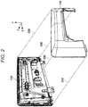
FIG. 2 is a diagram illustrating an assembling direction in an assembling work of assembling a rear panel to a front panel. -
FIG. 3 is a diagram illustrating an arrangement of abutting portions. -
FIGS. 4A and 4B are diagrams illustrating a part of a combination of a first abutting portion and a second abutting portion disposed at a corner part of a display device. -
FIGS. 5A and 5B are diagrams illustrating a combination of the first abutting portion and the second abutting portion disposed at a long side part of the display device. -
FIGS. 6A and 6B are diagrams illustrating a part of a combination of the first abutting portion and the second abutting portion disposed at a short side part of the display device. -
FIGS. 7A to 7C are diagram schematically illustrating a state at the time of assembling the first abutting portion and the second abutting portion. -
FIGS. 8A to 8C are diagrams schematically illustrating another example of the second abutting portion. -
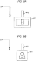
FIGS. 9A and 9B are diagrams schematically illustrating another example of the first abutting portion. - Hereinafter, embodiments will be described with reference to the attached drawings. In the present specification and the drawings, constituent elements having substantially the same functional configuration are denoted by the same reference numerals, and the repeated description thereof will not be provided.
- First, a display device, which is an example of an electronic device having an assembly structure according to the first embodiment as an external component, will be described. Further, the display device referred to here includes, for example, a liquid crystal display device, a plasma display device, an organic electroluminescence (EL) display device and the like.
-
FIGS. 1A and 1B are diagrams illustrating an external configuration of a display device.FIG. 1A is a front perspective view of thedisplay device 100, andFIG. 1B is a rear perspective view of thedisplay device 100. - As illustrated in
FIG. 1A , thedisplay device 100 has afront panel 110 as an external component which is an assembly structure according to the first embodiment. Further, as illustrated inFIG. 1B , thedisplay device 100 has arear panel 120 as an external component which is the assembly structure according to the first embodiment. - An assembling process of the
display device 100 includes an assembling work of assembling therear panel 120 to thefront panel 110 to which adisplay module 111, aholder 121, and the like are attached. - Next, the assembling direction in the assembling work of assembling the
rear panel 120 to thefront panel 110 will be described.FIG. 2 is a diagram illustrating the assembling direction in the assembling work of assembling the rear panel to the front panel. - As illustrated in
FIG. 2 , in the assembling work, by moving therear panel 120 along anarrow 200, therear panel 120 is assembled to thefront panel 110. That is, in the example ofFIG. 2 , therear panel 120 is an assembling component, and thefront panel 110 is an assembled component. Thearrow 200 is a direction substantially orthogonal to the surface of the display module 111 (not illustrated inFIG. 2 ) attached to thefront panel 110, and in the first embodiment, this direction is referred to as an "assembling direction". Further, in the first embodiment, the assembling direction is defined as a Z-axis direction. - Further, in the direction substantially parallel to the surface of the
display module 111, a direction substantially parallel to the long side direction of thedisplay module 111 is defined as an X-axis direction, and a direction substantially parallel to the short side direction of the display module is defined as a Y-axis direction. Both the X-axis direction and the Y-axis direction are directions substantially orthogonal to the assembling direction. - Next, the arrangement of the "abutting portions" which abut against each other by assembling the
rear panel 120 to thefront panel 110 to restrict the movement between thefront panel 110 and therear panel 120 will be described. - In the first embodiment, the abutting portions of the
front panel 110 and therear panel 120 can be broadly divided into two types. - The first abutting portion is an abutting portion that restricts the movement in the Z-axis direction between the
rear panel 120 and thefront panel 110 in a state in which therear panel 120 is assembled to thefront panel 110. - The second abutting portion is an abutting portion which restricts one of the movement in the X-axis direction, the movement in the Y-axis direction or both movements in the X-axis direction and the Y-axis direction between the
rear panel 120 and thefront panel 110, in the state in which therear panel 120 is assembled to thefront panel 110. -
FIG. 3 is a diagram illustrating the arrangement of the abutting portions. InFIG. 3 ,circles 301 illustrate the positions at which the first abutting portion for restricting the movement in the Z-axis direction is disposed. In addition, circles 302 illustrate the positions at which the second abutting portion for restricting the movement in the X-axis direction is disposed.Circles 303 illustrate the positions at which the second abutting portion for restricting the movement in the Y-axis direction is disposed. Further, circles 304 illustrate the position at which the second abutting portion for restricting the movement in both the X-axis direction and the Y-axis direction is disposed. - As indicated by
dotted lines 310 to 380 inFIG. 3 , in each part (corner parts, long side parts, and short side parts) of the "outer circumferential surface" formed by assembling therear panel 120 to thefront panel 110, a plurality of combinations of the first abutting portion and the second abutting portion are disposed. Specifically, combinations indicated bydotted lines dotted lines 330 to 360 are disposed at the long side parts, and combinations indicated bydotted lines - In this way, it is possible to suppress sliding between the
rear panel 120 and thefront panel 110, by disposing the combinations of the first abutting portion and the second abutting portion in each part. - Next, detailed configurations of the first abutting portion and the second abutting portion will be described.
FIGS. 4A and 4B are diagrams illustrating a part of a combination (dottedline 320 inFIG. 3 ) of the first abutting portion and the second abutting portion disposed at the corner part of the display device. - Among them,
FIG. 4A illustrates an aspect in which the corner part of therear panel 120 of thedisplay device 100 is viewed from the interior, andFIG. 4B illustrates an aspect in which the corner part of thefront panel 110 of thedisplay device 100 is viewed from the interior. - As illustrated in
FIG. 4A ,hook members circle 301 of therear panel 120. As illustrated inFIG. 4B ,hook receiving members circle 301 of thefront panel 110. - When the
hook member 412 or the like is locked to thehook receiving member 411 or the like in the state of assembling therear panel 120 to thefront panel 110, thehook receiving member 411 or the like can restrict the movement in a direction opposite to the assembling direction of thehook member 412 or the like. As a result, according to the first abutting portion indicated by thecircle 301, it is possible to avoid therear panel 120 from sliding in the direction opposite to the assembling direction with respect to thefront panel 110. - Further, as illustrated in
FIG. 4A , at the position indicated by acircle 302 of therear panel 120, as a second abutting portion for restricting the movement in the X-axis direction, a protrudingmember 432 extending in the Z-axis direction is disposed. The protrudingmember 432, and the abuttingportion 433 on thefront panel 110 side against which the protrudingmember 432 butts form a part of the locking member which locks thehook member 412 or the like so as not to move in the assembling direction in a state in which therear panel 120 is assembled to thefront panel 110. Further, as illustrated inFIG. 4B , at the position indicated by thecircle 302 of thefront panel 110, as a second abutting portion for restricting the movement in the X-axis direction, a rigidfitting member 431 having a strong fitting shape is disposed. - When the
rear panel 120 is assembled to thefront panel 110, since a part (the protrusion in the X-axis direction) of the rigidfitting member 431 is plastically deformed by the protrudingmember 432, the rigidfitting member 431 rigidly fits the protrudingmember 432. Accordingly, the rigidfitting member 431 can restrict the movement of the protrudingmember 432 in the X-axis direction. As a result, according to the second abutting portion indicated by thecircle 302, it is possible to avoid therear panel 120 from sliding in the X-axis direction with respect to thefront panel 110. - Further, as illustrated in
FIG. 4A , at a position (a position corresponding to the position at which the curved surface is formed, on the outer circumferential surface) indicated by acircle 304 of therear panel 120, as a second abutting portion for restricting movement in the X-axis direction and the Y-axis direction, a protrudingmember 442 extending in the Z-axis direction is disposed. Further, as illustrated inFIG. 4B , at the position indicated by thecircle 304 of thefront panel 110, as a second abutting portion for restricting the movement in the X-axis direction and the Y-axis direction, a rigidfitting member 441 is disposed. - When the
rear panel 120 is assembled to thefront panel 110, since a part of the rigidfitting member 441 is plastically deformed by the protrudingmember 442, the rigidfitting member 441 rigidly fits the protrudingmember 442. At this time, the plastically deformed part is a protrusion extending in a direction of approximately 45 degrees with respect to the X-axis direction and approximately 45 degrees with respect to the Y-axis direction. Therefore, the rigidfitting member 441 can restrict the movement of the protrudingmember 442 in the X-axis direction and the Y-axis direction. As a result, according to the second abutting portion indicated by acircle 304, it is possible to avoid therear panel 120 from sliding in the X-axis direction and sliding in the Y-axis direction with respect to thefront panel 110. - In this way, by providing a configuration that avoids the first abutting portion and the second abutting portion from sliding in the Z-axis direction, the X-axis direction and the Y-axis direction, respectively, it is possible to suppress an occurrence of squeaking sound.
- In addition, by disposing the second abutting portion in the vicinity of the first abutting portion, it is possible to suppress the occurrence of squeaking sound caused by sliding at the first abutting portion in the X-axis direction or the Y-axis direction.
-
FIGS. 5A and 5B are diagrams illustrating a combination (dottedline 350 inFIG. 3 ) of the first abutting portion and the second abutting portion disposed at the long side part of the display device. -
FIG. 5A illustrates an aspect in which the long side part of therear panel 120 of thedisplay device 100 is viewed from the interior, andFIG. 5B illustrates an aspect in which the long side part of thefront panel 110 of thedisplay device 100 is viewed from the interior. - As illustrated in
FIG. 5A , at a position (a position corresponding to a position at which a flat surface is formed, on the outer circumferential surface) indicated by acircle 301 of therear panel 120, as the first abutting portion, ahook member 512 extending in the Z-axis direction is disposed. Further, as illustrated inFIG. 5B , ahook receiving member 511 is disposed as the first abutting portion at a position indicated by acircle 301 of thefront panel 110. - When the
hook member 512 is locked to thehook receiving member 511 in a state in which therear panel 120 is assembled to thefront panel 110, thehook receiving member 511 restricts the movement in the direction opposite to the assembling direction of thehook member 512. As a result, according to the first abutting portion indicated by thecircle 301, it is possible to avoid therear panel 120 from sliding with respect to thefront panel 110 in the direction opposite to the assembling direction. - Further, as illustrated in
FIG. 5A , at a position (a position corresponding to a position at which a flat surface is formed, on the outer circumferential surface) indicated by acircle 303 of therear panel 120, as the second abutting portion for restricting the movement in the Y-axis direction, protrudingmembers members portions front panel 110 side against which the protrudingmembers hook member 512 so as not to move in the assembling direction, in a state in which therear panel 120 is assembled to thefront panel 110. Further, as illustrated inFIG. 5B ,strong engagement members circle 303 of thefront panel 110. - When the
rear panel 120 is assembled to thefront panel 110, some parts (protrusions disposed in the Y-axis direction substantially orthogonal to the flat surface) of the rigidfitting members members fitting members members members circle 303, it is possible to avoid therear panel 120 from sliding with respect to thefront panel 110 in the Y-axis direction. - In this way, by providing a configuration in which the first abutting portion and the second abutting portion do not slide in the Z-axis direction and the Y-axis direction, respectively, it is possible to suppress the occurrence of squeaking sound.
- In addition, by disposing the first abutting portion so as to be interposed by the second abutting portions, it is possible to further suppress the occurrence of squeaking sound caused by sliding at the first abutting portion in the Y-axis direction.
-
FIGS. 6A and 6B are diagrams illustrating a part of a combination (dottedline 380 inFIG. 3 ) of the first abutting portion and the second abutting portion disposed at the short side part of the display device. -
FIG. 6A illustrates an aspect in which the short side part of thefront panel 110 of thedisplay device 100 is viewed from the interior, andFIG. 6B illustrates an aspect in which the short side part of therear panel 120 of thedisplay device 100 is viewed from the interior. - As illustrated in
FIG. 6A , at a position (a position corresponding to a position at which a flat surface is formed on the outer circumferential surface) indicated by acircle 301 of thefront panel 110, ahook receiving member 611 is disposed as a first abutting portion. As illustrated inFIG. 6B , at a position indicated by thecircle 301 of therear panel 120, twohook members 612 extending in the Z-axis direction are disposed as the first abutting portions. - When the
hook member 612 is locked to thehook receiving member 611 in the state of assembling therear panel 120 to thefront panel 110, thehook receiving member 611 can restrict the movement in the direction opposite to the assembling direction of thehook member 612. As a result, according to the first abutting portion indicated by thecircle 301, it is possible to avoid therear panel 120 from sliding with respect to thefront panel 110 in the direction opposite to the assembling direction. - Further, as illustrated in
FIG. 6A , at a position (a position corresponding to a position at which a flat surface is formed, on the outer circumferential surface) indicated by acircle 302 of thefront panel 110, a rigidfitting member 621 is disposed as a second abutting portion which restricts the movement in the X-axis direction. Further, as illustrated inFIG. 6B , at a position indicated by acircle 302 of therear panel 120, a protrudingmember 622 extending in the Z-axis direction is disposed as a second abutting portion which restricts the movement in the X-axis direction. - When assembling the
rear panel 120 to thefront panel 110, a part (a protrusion disposed to face the X-axis direction substantially orthogonal to the flat surface) of the rigidfitting member 621 is plastically deformed by the protrudingmember 622. Therefore, the rigidfitting member 621 rigidly fits the protrudingmember 622 and can restrict the movement of the protrudingmember 622 in the X-axis direction. As a result, according to the second abutting portion indicated by acircle 302, it is possible to avoid therear panel 120 from sliding with respect to thefront panel 110 in the X-axis direction. - In this way, by providing a configuration in which the first abutting portion and the second abutting portion do not slide in the Z-axis direction and the X-axis direction, respectively, it is possible to suppress the occurrence of squeaking sound.
- In addition, by disposing the second abutting portion in the vicinity of the first abutting portion, it is possible to further suppress the occurrence of squeaking sound caused by sliding in the X-axis direction at the first abutting portion.
- Next, functions of the first abutting portion and the second abutting portion at the time of assembling will be described.
FIGS. 7A to 7C are diagrams schematically illustrating an aspect at the time of assembling the first abutting portion and the second abutting portion. - Among them,
FIG. 7A is a diagram schematically illustrating an aspect at the time of assembling the first abutting portion. By moving therear panel 120 in the assembling direction, thehook member 412 moves in the Z-axis direction (see reference numeral 710) as illustrated inFIG. 7A . Thehook member 412 moves in the Z-axis direction while being elastically deformed when abutting against the hook receiving member 411 (see reference numeral 711). When thehook member 412 reaches the opening portion of thehook receiving member 411, thehook member 412 is locked to the hook receiving member 411 (see reference numeral 712). In this way, in thehook member 412, the intersection between thefront panel 110 and therear panel 120 is absorbed by being elastically deformed at the time of assembling. -
FIG. 7B is a diagram schematically illustrating an aspect at the time of assembling the second abutting portion which restricts the movement in the X-axis direction. By moving therear panel 120 in the assembling direction, the protrudingmember 622 moves in the Z-axis direction (see reference numeral 720) as illustrated inFIG. 7B . When the protrudingmember 622 abuts against a part (theprotrusion 701 in the X-axis direction) of the rigidfitting member 621, the protrudingmember 622 moves in the Z-axis direction while plastically deforming theprotrusion 701 in the X-axis direction of the rigid fitting member 621 (see reference numeral 721) to reach the abutting portion of the rigid fitting member 621 (see reference numeral 722). - Here, as illustrated in
FIG. 7B , a length Wf1 of the rigidfitting member 621 in the X-axis direction is longer than a length Wr1 of the protrudingmember 622 in the X-axis direction. Therefore, the intersection between thefront panel 110 and therear panel 120 can be absorbed by a difference between the length Wf1 and the length Wr1. As a result, according to the second abutting portion which restricts the movement in the X-axis direction, it is possible to avoid a situation in which the assembling work becomes difficult. - Further, in the example of
FIG. 7B , theprotrusion 701 in the X-axis direction has a shape disposed in a part of the rigidfitting member 621 in the Z-axis direction, as a strong fitting shape. However, theprotrusion 701 in the X-axis direction may have a shape disposed in the entire Z-axis direction of the rigidfitting member 621. -
FIG. 7C is a diagram schematically illustrating the aspect at the time of assembling the second abutting portion for restricting the movement in the Y-axis direction. By moving therear panel 120 in the assembling direction, as illustrated inFIG. 7C , the protrudingmember 522 moves in the Z-axis direction (see reference numeral 730). When the protrudingmember 522 abuts against a part (theprotrusion 702 in the Y-axis direction) of the rigidfitting member 521, the protrudingmember 522 moves in the Z-axis direction, while plastically deforming theprotrusion 702 of the rigidfitting member 521 in the Y-axis direction (see reference numeral 731) to reach the abutting portion of the rigid fitting member 521 (see reference numeral 732). - Here, as illustrated in
FIG. 7C , a length Wf2 of the rigidfitting member 621 in the Y-axis direction is longer than a length Wr2 of the protrudingmember 522 in the Y-axis direction. Therefore, the intersection between thefront panel 110 and therear panel 120 can be absorbed by the difference between the length Wf2 and the length Wr2. As a result, according to the second abutting portion that restricts the movement in the Y-axis direction, it is possible to avoid a situation in which the assembling work becomes difficult. - In the example of
FIG. 7C , theprotrusion 702 in the Y-axis direction has a shape disposed in a part of the rigidfitting member 521 in the Z-axis direction as a strong fitting shape, but theprotrusion 702 in the Y-axis direction may have a shape disposed in the entire Z-axis direction of the rigidfitting member 521. - Further, the
hook member 412 ofFIG. 7A is configured to be locked to thehook receiving member 411, in a state in which each of the protrudingmembers FIGS. 7B and 7C reaches the abutting portions of the rigidfitting members hook member 412 in the assembling direction of the first abutting portion is restricted by the second abutting portion (abutting portions of the rigidfitting members 621 and 521). As a result, according to the second abutting portion, it is possible to avoid therear panel 120 from sliding in the assembling direction with respect to thefront panel 110. - As is apparent from the above description, in the first embodiment, in the assembly structure of the
front panel 110 and therear panel 120, as the first abutting portion,
an elastically deformable hook member extending in the assembling direction (Z-axis direction) is disposed in therear panel 120,
a hook receiving member to be hooked by the hook member is disposed on thefront panel 110,
by locking the hook member to the hook receiving member in the state of assembling therear panel 120 to thefront panel 110, movement in the direction opposite to the assembling direction is restricted, and
a protruding member extending in the assembling direction (Z-axis direction) is disposed in therear panel 120, the abutting portion is provided on thefront panel 110, when the protruding member butts against the abutting portion, the movement in the assembling direction is restricted, and the hook member does not move along the assembling direction. - Further, in the assembly structure, as the second abutting portion,
a protruding member extending in the assembling direction (Z-axis direction) is disposed on therear panel 120,
a rigid fitting member which rigidly fits the protruding member is disposed on thefront panel 110,
in a state in which therear panel 120 is assembled to thefront panel 110, the rigid fitting member rigidly fits the protruding member to restrict the movement of the protruding member in the X-axis direction or the Y-axis direction or both substantially orthogonal to the assembling direction. - As a result, even when an external force is applied in the X-axis direction, the Y-axis direction or the Z-axis direction after assembling, it is possible to avoid a situation in which the
rear panel 120 slides with respect to thefront panel 110 and suppress the occurrence of squeaking sound. - Further, according to the above configuration, since the intersection between the
front panel 110 andrear panel 120 can be absorbed by the elastically deformed protrusion and the plastically deformed hook member, it is possible to avoid the situation in which the assembling work becomes difficult. - That is, according to the first embodiment, it is possible to provide an assembly structure that can facilitate the assembling work and can suppress the occurrence of squeaking sounds even when an external force is applied after assembling.
- In the first embodiment, as the second abutting portion, the rigid fitting member having the protrusion in a predetermined axial direction (for example, the rigid
fitting member 621 having theprotrusion 701 in the X-axis direction, and the rigidfitting member 521 having theprotrusion 702 in the Y-axis direction) is disposed. However, the shape of the rigid fitting member in the second abutting portion is not limited thereto. For example, a shape having a plurality of protrusions in different axial directions may be used. -
FIGS. 8A to 8C are diagrams schematically illustrating another example of the second abutting portion, and are schematic views when thefront panel 110 is viewed from the interior. InFIGS. 8A to 8C , a solid line illustrates the rigid fitting member disposed on thefront panel 110 side as the second abutting portion, and a dotted line illustrates the protruding member disposed on therear panel 120 side as the second abutting portion. - Among them,
FIG. 8A schematically illustrates a relation between the protrudingmember 522 and the rigidfitting member 521 illustrated in the first embodiment for comparison. On the other hand,FIGS. 8B and 8C schematically illustrate a relation between the protruding member and the rigid fitting member in the second embodiment. - As illustrated in
FIG. 8A , in the first embodiment, for example, a pair ofprotrusions 702 is provided at positions facing each other in the Y-axis direction to restrict the movement in the Y-axis direction. In contrast, as illustrated inFIG. 8B , in the second embodiment, a pair ofprotrusions 801 is disposed at positions facing each other in the X-axis direction, and a pair ofprotrusions 802 is provided at positions facing each other in the Y-axis direction. Furthermore, in the second embodiment, the protruding member is formed in a cylindrical shape and the rigid fitting member is formed in a cylindrical shape. - In this way, by disposing the protrusions at the positions facing each other in the X-axis direction and in the Y-axis direction, respectively, in the second embodiment, in the second abutting portion, it is possible to restrict the movement of the protruding member both in the X-axis direction and the Y-axis direction.
- Alternatively, as illustrated in
FIG. 8C , in the second embodiment, theprotrusions 811 to 813 are disposed at three positions, the protruding member is formed in a triangular prism shape, and the rigid fitting member is formed in a cylindrical shape. - In this way, by disposing the protrusions at three positions, in the second embodiment, at the second abutting portion, it is possible to restrict the movement of the protruding member in an arbitrary direction substantially orthogonal to the Z-axis direction.
- As described above, according to the second embodiment, it is possible to restrict the movement in a plurality of directions substantially orthogonal to the Z-axis direction at one position of the second abutting portion.
- In the first embodiment, as the first abutting portion, a hook receiving member having a rectangular opening portion is disposed on the
front panel 110 side. In contrast, in the third embodiment, a hook receiving member having a trapezoidal shaped opening portion is disposed as the first abutting portion on thefront panel 110 side. -
FIGS. 9A and 9B are diagrams schematically illustrating another example of the first abutting portion, and are schematic views when the state of locking the hook receiving member to the hook member is viewed from the interior of thefront panel 110. - Among them,
FIG. 9A schematically illustrates thehook member 412 and thehook receiving member 411 described in the first embodiment for comparison. On the other hand,FIG. 9B schematically illustrates thehook member 412 and thehook receiving member 911 in the third embodiment. - As illustrated in
FIG. 9B , by forming the opening portion of thehook receiving member 911 into a trapezoidal shape, even when an external force is applied in the X-axis direction, thehook member 412 is hard to shift in the X-axis direction. That is, according to the third embodiment, it is possible to make it difficult for the first abutting portion to slide against an external force in a direction substantially orthogonal to the Z-axis direction. - In the aforementioned first embodiment, the material of the protrusion of the rigid fitting member is not particularly mentioned, but the material of the protrusion may be the same as or different from the material of the front panel 110 (the shape may be a shape that is easily plastically deformed, and the material thereof is arbitrary).
- In the first embodiment, in the first abutting portion, the hook member is disposed on the
rear panel 120 side and the hook receiving member is disposed on thefront panel 110 side. However, the hook member may be disposed on thefront panel 110 side and the hook receiving member may be disposed on therear panel 120 side. - Further, in the first embodiment, in the second abutting portion, the protruding member is disposed on the
rear panel 120 side and the rigid fitting member is disposed on thefront panel 110 side. However, a protruding member may be disposed on thefront panel 110 side and a rigid fitting member may be disposed on therear panel 120 side. - Further, in the first embodiment, the
rear panel 120 is illustrated as being assembled to thefront panel 110, but the assembling direction may be opposite. That is, thefront panel 110 may be assembled to therear panel 120. - Further, in the first embodiment, four sets (dotted
lines 330 to 360 ofFIG. 3 ) of combinations of the first abutting portion and the second abutting portion for restricting the movement in the Y-axis direction are illustrated as being disposed at the long side part of thedisplay device 100. However, the number of combinations of the abutting portions disposed at the long side part is not limited thereto. - Further, in the first embodiment, the combination of the abutting portions disposed at the long side part of the
display device 100 includes one first abutting portion and two second abutting portions, but the number and the arrangement of the abutting portions included in the combination of the abutting portions are not limited thereto. Further, the same also applies to the combination of the abutting portions disposed at the short side part and the corner part, and the number and the arrangement of the abutting portions included in the combination of the abutting portions illustrated in the first embodiment are only an example. - Further, in each of the above-described embodiments, the
display device 100 has been described as an example of the external component of the electronic device to which the assembly structure is applied, but the invention may be applied to the external components of the electronic device other than thedisplay device 100. - Further, the present invention is not limited to the configurations described in the above embodiments, and the configurations illustrated here such as combinations with other elements. These points can change within a scope that does not depart from the gist of the present invention, and can be appropriately determined according to the application form.
-
- 100: display device
- 110: front panel
- 120: rear panel
- 301: circle (position of first abutting portion)
- 302: circle (position of second abutting portion that restricts movement in X-axis direction)
- 303: circle (position of second abutting portion that restricts movement in Y-axis direction)
- 304: circle (position of second abutting portion that restricts movement in X-axis direction and Y-axis direction)
- 411, 421: hook receiving member
- 412, 422: hook member
- 431, 441: rigid fitting member
- 432, 442: protruding member
- 433: abutting portion
- 511: hook receiving member
- 512: hook member
- 521, 531: rigid fitting member
- 522, 532: protruding member
- 611: hook receiving member
- 612: hook member
- 621: rigid fitting member
- 622: protruding member
- 523, 533: abutting portion
- 701, 702: protrusion
- 801: protrusion
- 811 to 813: protrusion
Claims (6)
- An assembly structure having an assembling component (120) and an assembled component (110) assembled to the assembling component (120), the assembly structure comprising:a first abutting portion (301) and a second abutting portion (302) in which the assembling component (120) and the assembled component (110) abut against each other when the assembled component (110) is assembled by the assembling component (120), characterized in thatthe first abutting portion (301) hasa hook member (422) extending in the assembling direction, anda locking member (421) which locks the hook member (412) so as not to move along the assembling direction in a state in which the assembled component (110) is assembled to the assembling component (120), andthe second abutting portion (302) hasa protruding member (432) extending in the assembling direction, anda rigid fitting member (431) which rigidly fits the protruding member (432) by being plastically deformed by the protruding member (432) when the assembled component (110) is assembled to the assembling component (120), thereby restricting the movement of the protruding member (432) in a direction substantially orthogonal to the assembling direction.
- The assembly structure according to claim 1, characterized in that the second abutting portion (304) is disposed at a position corresponding to a position at which a curved surface is formed, on an outer circumferential surface formed by the assembled component (110) and the assembling component (120), in a state in which the assembled component (110) is assembled by the assembling component (120).
- The assembly structure according to claim 1 or 2, characterized in that the first abutting portion (301) is disposed to be interposed between two second abutting portions (303) at a position corresponding to a position, at which a flat surface is formed, on the outer circumferential surface.
- The assembly structure according to claim 3, characterized in that protrusions (702) plastically deformed by protruding members (522, 532) are disposed on rigid fitting members (521, 531) of the second abutting portion (303) in a direction substantially orthogonal to the flat surface to face each other.
- The assembly structure according to one of claims 1-4, characterized in that protrusions (801, 802) plastically deformed by the protruding member (432) are disposed on the rigid fitting member (431) in a plurality of directions substantially orthogonal to the assembling direction.
- The assembly structure according to one of claims 1-5, characterized in that
the hook member (422) is disposed on the assembling component (120) and the locking member (421) is disposed on the assembled component (110) at the first abutting portion (301), and
the protruding member (432) is disposed on the assembling component (120) and the rigid fitting member (431) is disposed on the assembled component (110) at the second abutting portion (302).
Applications Claiming Priority (1)
| Application Number | Priority Date | Filing Date | Title |
|---|---|---|---|
| JP2017007909A JP2018117075A (en) | 2017-01-19 | 2017-01-19 | Assembly structure |
Publications (3)
| Publication Number | Publication Date |
|---|---|
| EP3352538A2 true EP3352538A2 (en) | 2018-07-25 |
| EP3352538A3 EP3352538A3 (en) | 2018-08-08 |
| EP3352538B1 EP3352538B1 (en) | 2021-12-08 |
Family
ID=60990674
Family Applications (1)
| Application Number | Title | Priority Date | Filing Date |
|---|---|---|---|
| EP18151442.3A Active EP3352538B1 (en) | 2017-01-19 | 2018-01-12 | Assembly structure |
Country Status (2)
| Country | Link |
|---|---|
| EP (1) | EP3352538B1 (en) |
| JP (1) | JP2018117075A (en) |
Families Citing this family (1)
| Publication number | Priority date | Publication date | Assignee | Title |
|---|---|---|---|---|
| JP7427641B2 (en) * | 2021-10-11 | 2024-02-05 | 矢崎総業株式会社 | display device |
Citations (1)
| Publication number | Priority date | Publication date | Assignee | Title |
|---|---|---|---|---|
| JP2001339174A (en) | 2000-05-30 | 2001-12-07 | Keihin Corp | Electronic component storage case |
Family Cites Families (8)
| Publication number | Priority date | Publication date | Assignee | Title |
|---|---|---|---|---|
| JPH0730525U (en) * | 1993-11-12 | 1995-06-06 | 住友電装株式会社 | Lock structure of protector for wire harness |
| JP2002267439A (en) * | 2001-03-06 | 2002-09-18 | Sony Corp | Rotation angle detector |
| JP4139287B2 (en) * | 2003-08-13 | 2008-08-27 | 矢崎総業株式会社 | Electrical junction box |
| JP2005109944A (en) * | 2003-09-30 | 2005-04-21 | Mitsumi Electric Co Ltd | headset |
| JP2006228964A (en) * | 2005-02-17 | 2006-08-31 | Fujitsu Ten Ltd | Fixing structure |
| WO2007046789A1 (en) * | 2005-10-17 | 2007-04-26 | Duel Systems | Electronic packages for peripheral devices |
| US9247656B2 (en) * | 2013-08-30 | 2016-01-26 | Western Digital Technologies, Inc. | Latch system |
| TWM530509U (en) * | 2016-06-04 | 2016-10-11 | 智易科技股份有限公司 | Electronic device casing and its disassembly fixture |
-
2017
- 2017-01-19 JP JP2017007909A patent/JP2018117075A/en active Pending
-
2018
- 2018-01-12 EP EP18151442.3A patent/EP3352538B1/en active Active
Patent Citations (1)
| Publication number | Priority date | Publication date | Assignee | Title |
|---|---|---|---|---|
| JP2001339174A (en) | 2000-05-30 | 2001-12-07 | Keihin Corp | Electronic component storage case |
Also Published As
| Publication number | Publication date |
|---|---|
| EP3352538B1 (en) | 2021-12-08 |
| EP3352538A3 (en) | 2018-08-08 |
| JP2018117075A (en) | 2018-07-26 |
Similar Documents
| Publication | Publication Date | Title |
|---|---|---|
| US8726473B2 (en) | Clipping fixation device allowing an adjustment in two directions | |
| JP2015110999A (en) | Clip | |
| US9413971B2 (en) | Opening and closing device, and electronic device | |
| US10292460B2 (en) | Fastener member, fastener structure, and support member | |
| EP3352538A2 (en) | Assembly structure | |
| US11229263B2 (en) | Hook device | |
| GB2625888A (en) | Holder for long member | |
| US9521762B2 (en) | Attachment structure | |
| JP6076731B2 (en) | Resin nail structure | |
| US11199213B2 (en) | Mounting structure and clip | |
| US20210102565A1 (en) | Assembly for locating and coupling components together | |
| US9471100B2 (en) | Electronic device | |
| US9708838B2 (en) | Vehicle door handle device | |
| JP2015082944A (en) | Clamp | |
| CN112739917B (en) | Fastener | |
| CN104070972B (en) | Sun shield device | |
| US20060151199A1 (en) | Wire binder | |
| JP6430884B2 (en) | Support unit and vehicle sun visor including the support unit | |
| JP6227897B2 (en) | Fastener | |
| JP2014016562A (en) | Display device | |
| JP2017089711A (en) | Component mounting structure | |
| WO2014103632A1 (en) | Structure for resin claw | |
| JP2017011326A (en) | Display device | |
| JP6636749B2 (en) | Fence mounting structure | |
| JP2014126117A (en) | Resin part locking structure |
Legal Events
| Date | Code | Title | Description |
|---|---|---|---|
| PUAI | Public reference made under article 153(3) epc to a published international application that has entered the european phase |
Free format text: ORIGINAL CODE: 0009012 |
|
| STAA | Information on the status of an ep patent application or granted ep patent |
Free format text: STATUS: THE APPLICATION HAS BEEN PUBLISHED |
|
| PUAL | Search report despatched |
Free format text: ORIGINAL CODE: 0009013 |
|
| AK | Designated contracting states |
Kind code of ref document: A2 Designated state(s): AL AT BE BG CH CY CZ DE DK EE ES FI FR GB GR HR HU IE IS IT LI LT LU LV MC MK MT NL NO PL PT RO RS SE SI SK SM TR |
|
| AX | Request for extension of the european patent |
Extension state: BA ME |
|
| RIC1 | Information provided on ipc code assigned before grant |
Ipc: H05K 5/00 20060101AFI20180628BHEP |
|
| AK | Designated contracting states |
Kind code of ref document: A3 Designated state(s): AL AT BE BG CH CY CZ DE DK EE ES FI FR GB GR HR HU IE IS IT LI LT LU LV MC MK MT NL NO PL PT RO RS SE SI SK SM TR |
|
| AX | Request for extension of the european patent |
Extension state: BA ME |
|
| STAA | Information on the status of an ep patent application or granted ep patent |
Free format text: STATUS: REQUEST FOR EXAMINATION WAS MADE |
|
| 17P | Request for examination filed |
Effective date: 20181105 |
|
| RBV | Designated contracting states (corrected) |
Designated state(s): AL AT BE BG CH CY CZ DE DK EE ES FI FR GB GR HR HU IE IS IT LI LT LU LV MC MK MT NL NO PL PT RO RS SE SI SK SM TR |
|
| STAA | Information on the status of an ep patent application or granted ep patent |
Free format text: STATUS: EXAMINATION IS IN PROGRESS |
|
| 17Q | First examination report despatched |
Effective date: 20201120 |
|
| GRAP | Despatch of communication of intention to grant a patent |
Free format text: ORIGINAL CODE: EPIDOSNIGR1 |
|
| STAA | Information on the status of an ep patent application or granted ep patent |
Free format text: STATUS: GRANT OF PATENT IS INTENDED |
|
| INTG | Intention to grant announced |
Effective date: 20210624 |
|
| GRAS | Grant fee paid |
Free format text: ORIGINAL CODE: EPIDOSNIGR3 |
|
| GRAA | (expected) grant |
Free format text: ORIGINAL CODE: 0009210 |
|
| STAA | Information on the status of an ep patent application or granted ep patent |
Free format text: STATUS: THE PATENT HAS BEEN GRANTED |
|
| AK | Designated contracting states |
Kind code of ref document: B1 Designated state(s): AL AT BE BG CH CY CZ DE DK EE ES FI FR GB GR HR HU IE IS IT LI LT LU LV MC MK MT NL NO PL PT RO RS SE SI SK SM TR |
|
| REG | Reference to a national code |
Ref country code: GB Ref legal event code: FG4D |
|
| REG | Reference to a national code |
Ref country code: AT Ref legal event code: REF Ref document number: 1454748 Country of ref document: AT Kind code of ref document: T Effective date: 20211215 Ref country code: CH Ref legal event code: EP |
|
| REG | Reference to a national code |
Ref country code: DE Ref legal event code: R096 Ref document number: 602018027749 Country of ref document: DE |
|
| REG | Reference to a national code |
Ref country code: IE Ref legal event code: FG4D |
|
| REG | Reference to a national code |
Ref country code: LT Ref legal event code: MG9D |
|
| REG | Reference to a national code |
Ref country code: NL Ref legal event code: MP Effective date: 20211208 |
|
| PG25 | Lapsed in a contracting state [announced via postgrant information from national office to epo] |
Ref country code: RS Free format text: LAPSE BECAUSE OF FAILURE TO SUBMIT A TRANSLATION OF THE DESCRIPTION OR TO PAY THE FEE WITHIN THE PRESCRIBED TIME-LIMIT Effective date: 20211208 Ref country code: LT Free format text: LAPSE BECAUSE OF FAILURE TO SUBMIT A TRANSLATION OF THE DESCRIPTION OR TO PAY THE FEE WITHIN THE PRESCRIBED TIME-LIMIT Effective date: 20211208 Ref country code: FI Free format text: LAPSE BECAUSE OF FAILURE TO SUBMIT A TRANSLATION OF THE DESCRIPTION OR TO PAY THE FEE WITHIN THE PRESCRIBED TIME-LIMIT Effective date: 20211208 Ref country code: BG Free format text: LAPSE BECAUSE OF FAILURE TO SUBMIT A TRANSLATION OF THE DESCRIPTION OR TO PAY THE FEE WITHIN THE PRESCRIBED TIME-LIMIT Effective date: 20220308 |
|
| REG | Reference to a national code |
Ref country code: AT Ref legal event code: MK05 Ref document number: 1454748 Country of ref document: AT Kind code of ref document: T Effective date: 20211208 |
|
| PG25 | Lapsed in a contracting state [announced via postgrant information from national office to epo] |
Ref country code: SE Free format text: LAPSE BECAUSE OF FAILURE TO SUBMIT A TRANSLATION OF THE DESCRIPTION OR TO PAY THE FEE WITHIN THE PRESCRIBED TIME-LIMIT Effective date: 20211208 Ref country code: NO Free format text: LAPSE BECAUSE OF FAILURE TO SUBMIT A TRANSLATION OF THE DESCRIPTION OR TO PAY THE FEE WITHIN THE PRESCRIBED TIME-LIMIT Effective date: 20220308 Ref country code: LV Free format text: LAPSE BECAUSE OF FAILURE TO SUBMIT A TRANSLATION OF THE DESCRIPTION OR TO PAY THE FEE WITHIN THE PRESCRIBED TIME-LIMIT Effective date: 20211208 Ref country code: HR Free format text: LAPSE BECAUSE OF FAILURE TO SUBMIT A TRANSLATION OF THE DESCRIPTION OR TO PAY THE FEE WITHIN THE PRESCRIBED TIME-LIMIT Effective date: 20211208 Ref country code: GR Free format text: LAPSE BECAUSE OF FAILURE TO SUBMIT A TRANSLATION OF THE DESCRIPTION OR TO PAY THE FEE WITHIN THE PRESCRIBED TIME-LIMIT Effective date: 20220309 Ref country code: ES Free format text: LAPSE BECAUSE OF FAILURE TO SUBMIT A TRANSLATION OF THE DESCRIPTION OR TO PAY THE FEE WITHIN THE PRESCRIBED TIME-LIMIT Effective date: 20211208 |
|
| PG25 | Lapsed in a contracting state [announced via postgrant information from national office to epo] |
Ref country code: NL Free format text: LAPSE BECAUSE OF FAILURE TO SUBMIT A TRANSLATION OF THE DESCRIPTION OR TO PAY THE FEE WITHIN THE PRESCRIBED TIME-LIMIT Effective date: 20211208 |
|
| PG25 | Lapsed in a contracting state [announced via postgrant information from national office to epo] |
Ref country code: SM Free format text: LAPSE BECAUSE OF FAILURE TO SUBMIT A TRANSLATION OF THE DESCRIPTION OR TO PAY THE FEE WITHIN THE PRESCRIBED TIME-LIMIT Effective date: 20211208 Ref country code: SK Free format text: LAPSE BECAUSE OF FAILURE TO SUBMIT A TRANSLATION OF THE DESCRIPTION OR TO PAY THE FEE WITHIN THE PRESCRIBED TIME-LIMIT Effective date: 20211208 Ref country code: RO Free format text: LAPSE BECAUSE OF FAILURE TO SUBMIT A TRANSLATION OF THE DESCRIPTION OR TO PAY THE FEE WITHIN THE PRESCRIBED TIME-LIMIT Effective date: 20211208 Ref country code: PT Free format text: LAPSE BECAUSE OF FAILURE TO SUBMIT A TRANSLATION OF THE DESCRIPTION OR TO PAY THE FEE WITHIN THE PRESCRIBED TIME-LIMIT Effective date: 20220408 Ref country code: EE Free format text: LAPSE BECAUSE OF FAILURE TO SUBMIT A TRANSLATION OF THE DESCRIPTION OR TO PAY THE FEE WITHIN THE PRESCRIBED TIME-LIMIT Effective date: 20211208 Ref country code: CZ Free format text: LAPSE BECAUSE OF FAILURE TO SUBMIT A TRANSLATION OF THE DESCRIPTION OR TO PAY THE FEE WITHIN THE PRESCRIBED TIME-LIMIT Effective date: 20211208 |
|
| PG25 | Lapsed in a contracting state [announced via postgrant information from national office to epo] |
Ref country code: PL Free format text: LAPSE BECAUSE OF FAILURE TO SUBMIT A TRANSLATION OF THE DESCRIPTION OR TO PAY THE FEE WITHIN THE PRESCRIBED TIME-LIMIT Effective date: 20211208 Ref country code: AT Free format text: LAPSE BECAUSE OF FAILURE TO SUBMIT A TRANSLATION OF THE DESCRIPTION OR TO PAY THE FEE WITHIN THE PRESCRIBED TIME-LIMIT Effective date: 20211208 |
|
| REG | Reference to a national code |
Ref country code: CH Ref legal event code: PL |
|
| REG | Reference to a national code |
Ref country code: DE Ref legal event code: R097 Ref document number: 602018027749 Country of ref document: DE |
|
| PG25 | Lapsed in a contracting state [announced via postgrant information from national office to epo] |
Ref country code: MC Free format text: LAPSE BECAUSE OF FAILURE TO SUBMIT A TRANSLATION OF THE DESCRIPTION OR TO PAY THE FEE WITHIN THE PRESCRIBED TIME-LIMIT Effective date: 20211208 Ref country code: IS Free format text: LAPSE BECAUSE OF FAILURE TO SUBMIT A TRANSLATION OF THE DESCRIPTION OR TO PAY THE FEE WITHIN THE PRESCRIBED TIME-LIMIT Effective date: 20220408 |
|
| REG | Reference to a national code |
Ref country code: BE Ref legal event code: MM Effective date: 20220131 |
|
| PLBE | No opposition filed within time limit |
Free format text: ORIGINAL CODE: 0009261 |
|
| STAA | Information on the status of an ep patent application or granted ep patent |
Free format text: STATUS: NO OPPOSITION FILED WITHIN TIME LIMIT |
|
| PG25 | Lapsed in a contracting state [announced via postgrant information from national office to epo] |
Ref country code: LU Free format text: LAPSE BECAUSE OF NON-PAYMENT OF DUE FEES Effective date: 20220112 Ref country code: DK Free format text: LAPSE BECAUSE OF FAILURE TO SUBMIT A TRANSLATION OF THE DESCRIPTION OR TO PAY THE FEE WITHIN THE PRESCRIBED TIME-LIMIT Effective date: 20211208 Ref country code: AL Free format text: LAPSE BECAUSE OF FAILURE TO SUBMIT A TRANSLATION OF THE DESCRIPTION OR TO PAY THE FEE WITHIN THE PRESCRIBED TIME-LIMIT Effective date: 20211208 |
|
| 26N | No opposition filed |
Effective date: 20220909 |
|
| PG25 | Lapsed in a contracting state [announced via postgrant information from national office to epo] |
Ref country code: SI Free format text: LAPSE BECAUSE OF FAILURE TO SUBMIT A TRANSLATION OF THE DESCRIPTION OR TO PAY THE FEE WITHIN THE PRESCRIBED TIME-LIMIT Effective date: 20211208 Ref country code: BE Free format text: LAPSE BECAUSE OF NON-PAYMENT OF DUE FEES Effective date: 20220131 |
|
| PG25 | Lapsed in a contracting state [announced via postgrant information from national office to epo] |
Ref country code: LI Free format text: LAPSE BECAUSE OF NON-PAYMENT OF DUE FEES Effective date: 20220131 Ref country code: CH Free format text: LAPSE BECAUSE OF NON-PAYMENT OF DUE FEES Effective date: 20220131 |
|
| PG25 | Lapsed in a contracting state [announced via postgrant information from national office to epo] |
Ref country code: IE Free format text: LAPSE BECAUSE OF NON-PAYMENT OF DUE FEES Effective date: 20220112 |
|
| PG25 | Lapsed in a contracting state [announced via postgrant information from national office to epo] |
Ref country code: IT Free format text: LAPSE BECAUSE OF FAILURE TO SUBMIT A TRANSLATION OF THE DESCRIPTION OR TO PAY THE FEE WITHIN THE PRESCRIBED TIME-LIMIT Effective date: 20211208 |
|
| PG25 | Lapsed in a contracting state [announced via postgrant information from national office to epo] |
Ref country code: HU Free format text: LAPSE BECAUSE OF FAILURE TO SUBMIT A TRANSLATION OF THE DESCRIPTION OR TO PAY THE FEE WITHIN THE PRESCRIBED TIME-LIMIT; INVALID AB INITIO Effective date: 20180112 |
|
| PG25 | Lapsed in a contracting state [announced via postgrant information from national office to epo] |
Ref country code: MK Free format text: LAPSE BECAUSE OF FAILURE TO SUBMIT A TRANSLATION OF THE DESCRIPTION OR TO PAY THE FEE WITHIN THE PRESCRIBED TIME-LIMIT Effective date: 20211208 Ref country code: CY Free format text: LAPSE BECAUSE OF FAILURE TO SUBMIT A TRANSLATION OF THE DESCRIPTION OR TO PAY THE FEE WITHIN THE PRESCRIBED TIME-LIMIT Effective date: 20211208 |
|
| PG25 | Lapsed in a contracting state [announced via postgrant information from national office to epo] |
Ref country code: MT Free format text: LAPSE BECAUSE OF FAILURE TO SUBMIT A TRANSLATION OF THE DESCRIPTION OR TO PAY THE FEE WITHIN THE PRESCRIBED TIME-LIMIT Effective date: 20211208 |
|
| PG25 | Lapsed in a contracting state [announced via postgrant information from national office to epo] |
Ref country code: TR Free format text: LAPSE BECAUSE OF FAILURE TO SUBMIT A TRANSLATION OF THE DESCRIPTION OR TO PAY THE FEE WITHIN THE PRESCRIBED TIME-LIMIT Effective date: 20211208 |
|
| PGFP | Annual fee paid to national office [announced via postgrant information from national office to epo] |
Ref country code: GB Payment date: 20260123 Year of fee payment: 9 |
|
| PGFP | Annual fee paid to national office [announced via postgrant information from national office to epo] |
Ref country code: DE Payment date: 20260121 Year of fee payment: 9 |
|
| PGFP | Annual fee paid to national office [announced via postgrant information from national office to epo] |
Ref country code: FR Payment date: 20260123 Year of fee payment: 9 |