EP3352404B1 - Procédé de correction de décalage de fréquence dans une communication v2v, et dispositif associé - Google Patents
Procédé de correction de décalage de fréquence dans une communication v2v, et dispositif associé Download PDFInfo
- Publication number
- EP3352404B1 EP3352404B1 EP16846885.8A EP16846885A EP3352404B1 EP 3352404 B1 EP3352404 B1 EP 3352404B1 EP 16846885 A EP16846885 A EP 16846885A EP 3352404 B1 EP3352404 B1 EP 3352404B1
- Authority
- EP
- European Patent Office
- Prior art keywords
- dmrs
- communication
- reference signal
- symbol
- mapped
- Prior art date
- Legal status (The legal status is an assumption and is not a legal conclusion. Google has not performed a legal analysis and makes no representation as to the accuracy of the status listed.)
- Active
Links
- 238000004891 communication Methods 0.000 title claims description 135
- 238000000034 method Methods 0.000 title claims description 28
- 238000013507 mapping Methods 0.000 claims description 30
- 230000005540 biological transmission Effects 0.000 description 40
- 238000012937 correction Methods 0.000 description 17
- 238000010586 diagram Methods 0.000 description 11
- 125000004122 cyclic group Chemical group 0.000 description 10
- 230000006870 function Effects 0.000 description 10
- 108010076504 Protein Sorting Signals Proteins 0.000 description 9
- 238000013461 design Methods 0.000 description 9
- 238000005259 measurement Methods 0.000 description 9
- 238000013468 resource allocation Methods 0.000 description 9
- 230000008859 change Effects 0.000 description 8
- 238000000794 confocal Raman spectroscopy Methods 0.000 description 7
- 238000011500 cytoreductive surgery Methods 0.000 description 7
- 238000005516 engineering process Methods 0.000 description 7
- 230000001360 synchronised effect Effects 0.000 description 7
- 230000000694 effects Effects 0.000 description 6
- 230000015654 memory Effects 0.000 description 6
- 230000008569 process Effects 0.000 description 5
- 238000010295 mobile communication Methods 0.000 description 4
- 230000004044 response Effects 0.000 description 4
- 101000741965 Homo sapiens Inactive tyrosine-protein kinase PRAG1 Proteins 0.000 description 3
- 102100038659 Inactive tyrosine-protein kinase PRAG1 Human genes 0.000 description 3
- 238000007726 management method Methods 0.000 description 3
- 238000012545 processing Methods 0.000 description 3
- 238000011160 research Methods 0.000 description 2
- 230000008054 signal transmission Effects 0.000 description 2
- 230000011664 signaling Effects 0.000 description 2
- 238000012546 transfer Methods 0.000 description 2
- 201000000913 Duane retraction syndrome Diseases 0.000 description 1
- 241000760358 Enodes Species 0.000 description 1
- 206010039203 Road traffic accident Diseases 0.000 description 1
- 230000004913 activation Effects 0.000 description 1
- 230000002776 aggregation Effects 0.000 description 1
- 238000004220 aggregation Methods 0.000 description 1
- 238000013459 approach Methods 0.000 description 1
- 238000003491 array Methods 0.000 description 1
- 230000001174 ascending effect Effects 0.000 description 1
- 238000004364 calculation method Methods 0.000 description 1
- 230000001413 cellular effect Effects 0.000 description 1
- 230000006835 compression Effects 0.000 description 1
- 238000007906 compression Methods 0.000 description 1
- 238000000162 direct recoil spectroscopy Methods 0.000 description 1
- 230000007774 longterm Effects 0.000 description 1
- 239000011159 matrix material Substances 0.000 description 1
- 238000012986 modification Methods 0.000 description 1
- 230000004048 modification Effects 0.000 description 1
- 230000001151 other effect Effects 0.000 description 1
- 230000000737 periodic effect Effects 0.000 description 1
- 230000009467 reduction Effects 0.000 description 1
- 230000001960 triggered effect Effects 0.000 description 1
Images


Classifications
-
- H—ELECTRICITY
- H04—ELECTRIC COMMUNICATION TECHNIQUE
- H04L—TRANSMISSION OF DIGITAL INFORMATION, e.g. TELEGRAPHIC COMMUNICATION
- H04L5/00—Arrangements affording multiple use of the transmission path
- H04L5/003—Arrangements for allocating sub-channels of the transmission path
- H04L5/0058—Allocation criteria
- H04L5/006—Quality of the received signal, e.g. BER, SNR, water filling
-
- H—ELECTRICITY
- H04—ELECTRIC COMMUNICATION TECHNIQUE
- H04L—TRANSMISSION OF DIGITAL INFORMATION, e.g. TELEGRAPHIC COMMUNICATION
- H04L27/00—Modulated-carrier systems
- H04L27/26—Systems using multi-frequency codes
-
- H—ELECTRICITY
- H04—ELECTRIC COMMUNICATION TECHNIQUE
- H04L—TRANSMISSION OF DIGITAL INFORMATION, e.g. TELEGRAPHIC COMMUNICATION
- H04L5/00—Arrangements affording multiple use of the transmission path
- H04L5/003—Arrangements for allocating sub-channels of the transmission path
- H04L5/0048—Allocation of pilot signals, i.e. of signals known to the receiver
- H04L5/0051—Allocation of pilot signals, i.e. of signals known to the receiver of dedicated pilots, i.e. pilots destined for a single user or terminal
-
- H—ELECTRICITY
- H04—ELECTRIC COMMUNICATION TECHNIQUE
- H04L—TRANSMISSION OF DIGITAL INFORMATION, e.g. TELEGRAPHIC COMMUNICATION
- H04L27/00—Modulated-carrier systems
- H04L27/0014—Carrier regulation
- H04L2027/0024—Carrier regulation at the receiver end
- H04L2027/0026—Correction of carrier offset
-
- H—ELECTRICITY
- H04—ELECTRIC COMMUNICATION TECHNIQUE
- H04L—TRANSMISSION OF DIGITAL INFORMATION, e.g. TELEGRAPHIC COMMUNICATION
- H04L5/00—Arrangements affording multiple use of the transmission path
- H04L5/0001—Arrangements for dividing the transmission path
- H04L5/0003—Two-dimensional division
- H04L5/0005—Time-frequency
- H04L5/0007—Time-frequency the frequencies being orthogonal, e.g. OFDM(A), DMT
Definitions
- the present invention relates to a wireless communication system, and more particularly, to a method for correcting a frequency offset in vehicle-to-vehicle (V2V) communication and apparatus for the same.
- V2V vehicle-to-vehicle
- V2X communication may be categorized into V2V (vehicle-to-vehicle) communication, V2P (vehicle-to-pedestrian) communication, and V2I (vehicle-to-infrastructure entity) communication.
- V2V communication may refer to communication between vehicles.
- V2P communication may refer to communication between a vehicle and a personally carried device (e.g., a handheld terminal of a pedestrian or a bicycle rider).
- V2I communication may refer to communication between a vehicle and a roadside unit (RSU).
- RSU may refer to a traffic infrastructure entity.
- RSU may include an entity that transmits a speed notification.
- a vehicle, an RSU and a handheld device may be equipped with a transceiver.
- V2X communication may be used to indicate warnings for various events such as safety and the like. For example, information on an event occurring on a vehicle or road may be notified to another vehicle or pedestrians through V2X communication. For example, information on a warning of a traffic accident, a road situation change, or an accident danger may be forwarded to another vehicle or pedestrian. For example, a pedestrian, who is adjacent to or crossing a road, can be informed of information on vehicle approach.
- U.S. patent application publication No. 2013/114756 A1 discusses a PUSCH reference signal design for high Doppler frequency.
- the 3GPP draft No. R1-154434 discusses considerations on the LTE V2X feasibility study.
- the V2X communication may have relatively low reliability.
- a phase may be sharply changed due to the Doppler effect.
- a channel state may also be changed rapidly due to vehicle movement.
- a method capable of achieving high reliability of communication is required.
- the present invention is proposed to solve the above-described problems, and particularly, the invention discloses a method for ensuring stable communication in various types of communication including V2X communication.
- the technical task of the present invention is to provide a method for correcting a frequency offset in V2X communication and apparatus for the same.
- a method for correcting a frequency offset by a user equipment (UE) in vehicle-to-vehicle (V2V) communication including: receiving a subframe including a reference signal from a transmitting end; and correcting the frequency offset based on the reference signal.
- the reference signal may be mapped to resource elements with either even or odd subcarrier indices in each of four symbols in the subframe.
- correcting the frequency offset may include comparing repeated signals repeated at a time interval corresponding to a first symbol among the four symbols, and each of the repeated signals may correspond to the reference signal mapped to the first symbol, wherein the reference signal includes a demodulation reference signal (DMRS), wherein the first symbol is composed of twelve resource elements, each having a subcarrier index, wherein a first DMRS sequence with a length of 6 is applied to the reference signal mapped to the first symbol, and wherein the first DMRS sequence is made up of part of a preconfigured second DMRS sequence with a length of 12.
- DMRS demodulation reference signal
- the four symbols may be equally spaced in the subframe.
- comparing the repeated signals may include comparing the repeated signals in a frequency domain by performing a Fast Fourier Transform (FFT) or a half-FFT on the repeated signals.
- FFT Fast Fourier Transform
- the corrected frequency offset may be applied to the first symbol and symbols adjacent to the first symbol.
- a user equipment (UE) for correcting a frequency offset in vehicle-to-vehicle (V2V) communication including: a transceiver; and a processor configured to control the transceiver.
- the processor may be further configured to: receive, from a transmitting end, a subframe including a reference signal which is mapped to resource elements with either even or odd subcarrier indices in each of four symbols in the subframe; and correct the frequency offset based on the reference signal by comparing repeated signals repeated at a time interval corresponding to a first symbol among the four symbols.
- each of the repeated signals may correspond to the reference signal mapped to the first symbol
- the reference signal includes a demodulation reference signal (DMRS), wherein the first symbol is composed of twelve resource elements, each having a subcarrier index, wherein a first DMRS sequence with a length of 6 is applied to the reference signal mapped to the first symbol, and wherein the first DMRS sequence is made up of part of a preconfigured second DMRS sequence with a length of 12.
- DMRS demodulation reference signal
- a vehicle means the vehicle which a terminal is mounted on, and it may be called a terminal.
- a road side unit may mean an infrastructure capable of connecting to a base station, relay or network.
- the base station may serve as a terminal node of the network over which the base station directly communicates with the terminal.
- specific operations illustrated as being conducted by the base station may also be conducted by an upper node of the base station.
- a pedestrian may mean the person moving on bicycle or the person carrying a terminal.
- the base station BS may be replaced with terms such as a fixed station, Node B, eNode B (eNB), and an access point (AP).
- a relay node may be replaced with terms such as a relay node (RN) and a relay station (RS).
- a terminal may be replaced with terms such as a user equipment (UE), a mobile station (MS), a mobile subscriber station (MSS), and a subscriber station (SS).
- the embodiments of the present invention may be supported by standard documents disclosed in at least one of wireless access systems, i.e., IEEE 802 system, 3GPP system, 3GPP LTE system, 3GPP LTE, 3GPP LTE-A (LTE-Advanced) system, and 3GPP2 system. Also, all terminologies disclosed herein may be described by the above standard documents.
- the following technology may be used for various wireless access systems such as CDMA (code division multiple access), FDMA (frequency division multiple access), TDMA (time division multiple access), OFDMA (orthogonal frequency division multiple access), and SC-FDMA (single carrier frequency division multiple access).
- the CDMA may be implemented by the radio technology such as universal terrestrial radio access (UTRA) or CDMA2000.
- the TDMA may be implemented by the radio technology such as global system for mobile communications (GSM)/general packet radio service (GPRS)/enhanced data rates for GSM evolution (EDGE).
- GSM global system for mobile communications
- GPRS general packet radio service
- EDGE enhanced data rates for GSM evolution
- the OFDMA may be implemented by the radio technology such as IEEE 802.11 (Wi-Fi), IEEE 802.16 (WiMAX), IEEE 802.20, and evolved UTRA (E-UTRA).
- the UTRA is a part of a universal mobile telecommunications system (UMTS).
- UMTS universal mobile telecommunications system
- a 3rd generation partnership project long term evolution (3GPP LTE) communication system is a part of an evolved UMTS (E-UMTS) that uses E-UTRA, and uses OFDMA in a downlink while uses SC-FDMA in an uplink.
- LTE-advanced (LTE-A) is an evolved version of the 3GPP LTE system.
- WiMAX may be described by the IEEE 802.16e standard (WirelessMAN-OFDMA Reference System) and the advanced IEEE 802.16m standard (WirelessMAN-OFDMA Advanced system). Although the following description will be based on the 3GPP LTE system and the 3GPP LTE-A system to clarify description, it is to be understood that the scope of the present invention is not limited to the 3GPP LTE and the 3GPP LTE-A system.
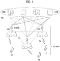
- the architecture of an LTE system which is an example of a wireless communication system to which the present invention is applicable, will be described with reference to FIG. 1 .
- the LTE system is a mobile communication system that has evolved from UMTS.
- the LTE system architecture may be broadly divided into an Evolved UMTS Terrestrial Radio Access Network (E-UTRAN) and an Evolved Packet Core (EPC).
- E-UTRAN includes a user equipment (UE) and an Evolved NodeB (eNB).
- UE user equipment
- eNB Evolved NodeB
- An interface between a UE and an eNB is referred to as a Uu interface
- an interface between eNBs is referred to as an X2 interface.
- the EPC includes a mobility management entity (MME) functioning as the control plane and a serving gateway (S-GW) functioning as the user plane.
- MME mobility management entity
- S-GW serving gateway
- An interface between an eNB and an MME is referred to as an S1-MME interface
- an interface between an eNB and an S-GW is referred to as an S1-U interface
- the two interfaces may also be called an S1 interface.
- a radio interface protocol is defined in the Uu interface which is a radio section, wherein the radio interface protocol is horizontally comprised of a physical layer, a data link layer and a network layer, and vertically divided into a user plane for user data transmission and a control plane for signaling (control signal) transfer.
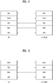
- a radio interface protocol may be typically classified into L1 (first layer) including a PHY which is a physical layer, L2 (second layer) including Media Access Control (MAC)/Radio Link Control (RLC)/Packet Data Convergence Protocol (PDCP) layers, and L3 (third layer) including a Radio Resource Control (RRC) layer as illustrated in FIGs. 2 and 3 , based on the three lower layers of the Open System Interconnection (OSI) reference model widely known in the field of communication systems.
- OSI Open System Interconnection
- FIG. 2 illustrates a control plane of a radio protocol
- FIG. 3 illustrates a user plane of a radio protocol.
- the physical (PHY) layer serving as the first layer (L1) provides an information transfer service for a higher layer using a physical channel.
- the PHY layer is connected to the Media Access Control (MAC) layer serving as a higher layer over a transport channel.
- MAC Media Access Control
- the transport channel Through the transport channel, data is transferred from the MAC layer to the physical layer and vice versa.
- the transport channel is broadly divided into a dedicated transport channel and a common transport channel depending on whether or not the channel is shared.
- data is transferred between different PHY layers, i.e., between a PHY layer of a transmitter and a PHY layer of a receiver over a physical channel using radio resources.
- the MAC layer serves to map various logical channels to various transport channels and to perform logical channel multiplexing of mapping a plurality of logical channels to one transport channel.
- the MAC layer is connected to the Radio Link Control (RLC) layer, which is a higher layer, through a logical channel.
- RLC Radio Link Control
- the logical channel is broadly divided into a control channel for transmitting information on the control plane and a traffic channel for transmitting information on the user plane according to the type of information to be transmitted.
- the RLC layer provides three RLC modes, namely, Transparent Mode (TM), Unacknowledged Mode (UM), and Acknowledged Mode (AM).
- TM Transparent Mode
- UM Unacknowledged Mode
- AM Acknowledged Mode
- the AM RLC performs a retransmission function using an Automatic Repeat and Request (ARQ) function so as to implement reliable data transmission.
- ARQ Automatic Repeat and Request
- the packet data convergence protocol (PDCP) layer of the L2 performs header compression to reduce the size of an IP packet header containing relatively large and unnecessary control information. This makes it possible to transmit only necessary information in the header portion of the data, thereby increasing the transmission efficiency of the radio section.
- the PDCP layer also performs a security function, which consists of a ciphering function to prevent a third party from intercepting data and an integrity protection function to prevent a third party from manipulating data.
- the Radio Resource Control (RRC) layer located at the top of the third layer (L3) is defined only in the control plane and is responsible for control of logical, transport, and physical channels in association with configuration, reconfiguration and release of Radio Bearers (RBs).
- the RB refers to a logical path that the L1 and L2 of the radio protocol provide for data communication between the UE and the UTRAN.
- configuring an RB means that a radio protocol layer and channel characteristics needed to provide a specific service are defined and detailed parameters and operation methods thereof are configured.
- the RB is divided into a Signaling RB (SRB) and a Data RB (DRB).
- SRB Signaling RB
- DRB Data RB
- an uplink (UL)/downlink (DL) data packet is transmitted on a subframe-by-subframe basis, and one subframe is defined as a predetermined time interval including a plurality of OFDM symbols.
- 3GPP LTE supports a type-1 radio frame structure applicable to frequency division duplex (FDD) and a type-2 radio frame structure applicable to time division duplex (TDD).
- FIG. 4 illustrates the type-1 radio frame structure.
- a downlink radio frame is divided into 10 subframes. Each subframe is further divided into two slots in the time domain.
- a unit time during which one subframe is transmitted is defined as transmission time interval (TTI).
- TTI transmission time interval
- one subframe may be 1ms in duration and one slot may be 0.5ms in duration.
- a slot may include a plurality of orthogonal frequency division multiplexing (OFDM) symbols in the time domain and includes a plurality of resource blocks (RBs) in the frequency domain. Because the 3GPP LTE system adopts OFDMA for downlink, an OFDM symbol represents one symbol period. An OFDM symbol may be referred to as an SC-FDMA symbol or symbol period.
- a Resource Block (RB) is a resource allocation unit including a plurality of contiguous subcarriers in a slot.
- FIG. 5 illustrates the type-2 radio frame structure.
- the type-2 radio frame includes two half frames each having 5 subframes, a downlink pilot time slot (DwPTS), a guard period (GP), and an uplink pilot time slot (UpPTS).
- Each subframe includes two slots.
- the DwPTS is used for initial cell search, synchronization, or channel estimation in a UE
- the UpPTS is used for channel estimation in an eNB and uplink transmission synchronization in a UE.
- the GP is a period between a downlink and an uplink, for eliminating interference with the uplink caused by multi-path delay of a downlink signal.
- a subframe is composed of two slots irrespective of radio frame type.
- radio frame structures are purely exemplary and thus it is to be noted that the number of subframes in a radio frame, the number of slots in a subframe, or the number of symbols in a slot may vary.
- FIG. 6 illustrates a resource grid for a downlink slot.
- a downlink slot includes 7 OFDM symbols in the time domain and an RB includes 12 subcarriers in the frequency domain, which does not limit the scope of the present invention as defined by the appended claims.
- a slot includes 7 OFDM symbols in the case of normal CP, whereas a slot includes 6 OFDM symbols in the case of extended CP.
- Each element of the resource grid is referred to as a resource element (RE).
- An RB includes 12x7 REs.
- the number of RBs in a downlink slot, NDL depends on a downlink transmission bandwidth.
- An uplink slot may have the same structure as a downlink slot.
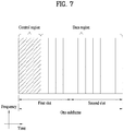
- FIG. 7 illustrates a downlink subframe structure.
- Up to three OFDM symbols at the start of the first slot in a downlink subframe are used for a control region to which control channels are allocated and the other OFDM symbols of the downlink subframe are used for a data region to which a PDSCH is allocated.
- Downlink control channels used in 3GPP LTE include a physical control format indicator channel (PCFICH), a physical downlink control channel (PDCCH), and a physical hybrid automatic repeat request (ARQ) indicator channel (PHICH).
- the PCFICH is located in the first OFDM symbol of a subframe, carrying information about the number of OFDM symbols used for transmission of control channels in the subframe.
- the PHICH delivers a HARQ acknowledgment/negative acknowledgment (ACK/NACK) signal in response to an uplink transmission.
- Control information carried on the PDCCH is called downlink control information (DCI).
- the DCI includes uplink resource allocation information, downlink resource allocation information or an uplink transmit (Tx) power control command for an arbitrary UE group.
- the PDCCH delivers information about resource allocation and a transport format for a Downlink Shared Channel (DL-SCH), resource allocation information about an Uplink Shared Channel (UL-SCH), paging information of a Paging Channel (PCH), system information on the DL-SCH, information about resource allocation for a higher-layer control message such as a Random Access Response transmitted on the PDSCH, a set of transmission power control commands for individual UEs of a UE group, transmission power control information, Voice Over Internet Protocol (VoIP) activation information, etc.
- a plurality of PDCCHs may be transmitted in the control region.
- a UE may monitor a plurality of PDCCHs.
- a PDCCH is formed by aggregation of one or more consecutive Control Channel Elements (CCEs).
- a CCE is a logical allocation unit used to provide a PDCCH at a coding rate based on the state of a radio channel.
- a CCE corresponds to a plurality of REs.
- the format of a PDCCH and the number of available bits for the PDCCH are determined according to the correlation between the number of CCEs and a coding rate provided by the CCEs.
- An eNB determines the PDCCH format according to DCI transmitted to a UE and adds a Cyclic Redundancy Check (CRC) to control information.
- the CRC is masked by an Identifier (ID) known as a Radio Network Temporary Identifier (RNTI) according to the owner or usage of the PDCCH.
- ID Identifier
- RNTI Radio Network Temporary Identifier
- the PDCCH is directed to a specific UE, its CRC may be masked by a cell-RNTI (C-RNTI) of the UE. If the PDCCH carries a paging message, the CRC of the PDCCH may be masked by a Paging Indicator Identifier (P-RNTI). If the PDCCH carries system information, particularly, a System Information Block (SIB), its CRC may be masked by a system information ID and a System Information RNTI (SI-RNTI). To indicate that the PDCCH carries a Random Access Response in response to a Random Access Preamble transmitted by a UE, its CRC may be masked by a Random Access-RNTI (RA-RNTI).
- SIB System Information Block
- SI-RNTI System Information RNTI
- RA-RNTI Random Access-RNTI
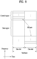
- FIG. 8 illustrates an uplink subframe structure.
- An uplink subframe may be divided into a control region and a data region in the frequency domain.
- a physical uplink control channel (PUCCH) carrying uplink control information is allocated to the control region and a physical uplink shared channel (PUSCH) carrying user data is allocated to the data region.
- PUSCH physical uplink shared channel
- a UE does not transmit a PUSCH and a PUCCH simultaneously.
- a PUCCH for a UE is allocated to an RB pair in a subframe. The RBs of the RB pair occupy different subcarriers in two slots. Thus it is said that the RB pair allocated to the PUCCH is frequency-hopped over a slot boundary.
- D2D communication various embodiments for a UE to perform device to device communication (hereinafter, D2D communication, D2D direct communication, etc.) are explained.
- D2D communication 3GPP LTE/LTE-A is mainly explained as an example.
- the D2D communication can also be applied to a different communication system (e.g., IEEE 802.16, WiMAX, etc.).
- D2D communication can be classified into a network coordinated D2D communication type and an autonomous D2D communication type according to whether a D2D communication is performed by a control of a network.
- the network coordinated D2D communication type can be classified again into a type of transmitting data only by D2D (data only in D2D) and a type of performing an access control only by a network (connection control only in network) according to the extent of involvement of the network.
- the type of transmitting data only by the D2D is called a 'network concentrated D2D communication type' and the type of performing access control only by the network is called a 'distributed D2D communication type' in the following.
- data is exchanged between D2D terminals only.
- An access control (connection control) and radio resource allocation (grant message) between the D2D terminals are performed by a network.
- the D2D terminals can transmit and receive data or specific control information using a radio resource allocated by the network. For instance, HARQ ACK/NACK feedback for the data reception between the D2D terminals or channel state information (CSI) is not directly exchanged between the D2D terminals. Instead, the feedback or the CSI can be transmitted to a different D2D terminal via the network.
- CSI channel state information
- a transmission D2D terminal and a reception D2D terminal can perform D2D communication using the allocated radio resource.
- D2D communication between D2D terminals is controlled by the network and the D2D terminals can perform D2D communication using a radio resource allocated by the network.
- a network according to the distributed D2D communication type performs a more limitative role compared to a network according to the network concentrated D2D communication type.
- the network in the distributed D2D communication type performs an access control between D2D terminals
- radio resource allocation (grant message) between the D2D terminals can be autonomously occupied by the D2D terminals via contention without a help of the network. For instance, HARQ ACK/NACK feedback for the reception of data between the D2D terminals or channel state information can be directly exchanged between the D2D terminals without passing through the network.
- D2D communication can be classified into the network concentrated D2D communication type and the distributed D2D communication type according to the extent of involvement of a network.
- a common characteristic between the network concentrated D2D communication type and the distributed D2D communication type is a D2D access control capable of being performed by the network.
- a network according to the network coordinated D2D communication type can establish a connection between D2D terminals in a manner of establishing a D2D link between the D2D terminals intending to perform D2D communication.
- the network can assign a physical D2D link identifier (LID) to the established D2D link.
- LID physical D2D link identifier
- the physical D2D link ID can be used as an identifier for identifying each of a plurality of D2D links in case that there are a plurality of the D2D links among a plurality of D2D terminals.
- D2D terminals can freely perform D2D communication without a help of a network.
- an access control, occupation of a radio resource and the like can be autonomously performed by the D2D terminals in the autonomous D2D communication type.
- the network may provide the D2D terminals with D2D channel information capable of being used in a corresponding cell.
- a terminal performing or capable of performing the D2D communication which is a direct communication between terminals, is called a D2D terminal (D2D terminal).
- D2D terminal a terminal performing or capable of performing the D2D communication
- a 'UE' may correspond to a D2D terminal.
- a transmission D2D terminal a terminal transmitting or intending to transmit data to a different D2D terminal using a radio resource given to a D2D link.
- a terminal receiving or intending to receive data from the transmission D2D terminal is called a reception D2D terminal.
- reception D2D terminals which receive or intend to receive data from the transmission D2D terminal
- a plurality of the reception D2D terminals can be distinguished from each other using a prefix such as 'first to N'.
- a prefix such as 'first to N'.
- a random node of a network as a base station configured to perform access control between D2D terminals or allocate a radio resource to a D2D link, a D2D server, an access/session management server and the like are commonly called a 'network' in the following description.
- the D2D terminal performs D2D peer discovery.
- the D2D terminal performs D2D discovery within a discovery interval and all D2D terminals may share the discovery interval.
- the D2D terminal monitors logical channels of a discovery region within the discovery interval to receive D2D discovery signals transmitted by different D2D terminals. Having received the signals of the different D2D terminals, the D2D terminal makes a list of adjacent D2D terminals using the received signal.
- the D2D terminal broadcasts information (i.e., an identifier) of the D2D terminal within the discovery interval and the different D2D terminals receive the broadcasted D2D discovery signal.
- the different D2D terminals are able to know that the D2D terminal exists within a range capable of performing D2D communication.
- Information broadcasting for D2D discovery can be periodically performed. And, broadcasting timing can be determined in advance by a protocol and can be notified to D2D terminals.
- the D2D terminal can transmit/broadcast a signal during a part of the discovery interval.
- Each of the D2D terminals may monitor signals potentially transmitted by different D2D terminals during the rest of the D2D discovery interval.
- a D2D discovery signal may correspond to a beacon signal.
- D2D discovery intervals may include a plurality of symbols (e.g., OFDM symbols).
- a D2D terminal selects at least one symbol belonging to a D2D discovery interval to transmit/broadcast a D2D discovery signal.
- the D2D terminal may transmit a signal corresponding to a tone of the symbol selected by the D2D terminal.
- D2D UEs After D2D UEs discovers each other through a D2D discovery process, the D2D UEs perform a connection establishment process. By doing so, one D2D UE can transmit traffic to the other D2D UE.
- FIG. 9 is a diagram for a simplified D2D communication network.
- D2D communication is performed between UEs (UE1 and UE2) supporting D2D communication.
- a user equipment corresponds to a terminal of a user.
- a network device as an eNB (evolved Node B) transmits and receives a signal according to a communication scheme between the UEs UE1 and UE2), the eNB can be considered as a UE as well.
- a UE1 selects a resource unit corresponding to a specific resource from a resource pool corresponding to a set of resources and the UE1 transmits a D2D signal using the selected resource unit.
- a UE2 corresponding to a reception UE receives a configuration of a resource pool in which the UE1 is able to transmit a signal and detects a signal of the UE1 in the resource pool.
- the eNB can inform the UE1 of the resource pool.
- the resource pool can be informed by a different UE or can be determined by a predetermined resource.
- a resource pool includes a plurality of resource units.
- a UE selects one or more resource units from among a plurality of the resource units and may be able to use the selected resource unit(s) for D2D signal transmission.
- FIG. 10 is a diagram for a configuration of a resource unit according to an example.
- a vertical axis corresponds to a frequency resource and a horizontal axis corresponds to a time resource.
- a radio resource is divided into the N T number of resource units in a time axis to configure the N T number of subframes.
- a frequency resource is divided into the N F number of resource units in a subframe.
- one subframe can include the N T number of symbols. In particular, it is able to define N F ⁇ N T number of resource units in total.
- a D2D transmission resource (unit #0) allocated to a unit number 0 is repeated in every N T number of subframes.
- a resource pool can be repeated with a period of the N T number of subframes.
- a specific resource unit may periodically and repeatedly appear.
- an index of a physical resource unit to which a logical resource unit is mapped may change according to a predetermined pattern to obtain a diversity gain in time domain and/or frequency domain.
- the logical resource unit can hop on time and/or frequency axis according to a predetermined pattern set to an actual physical resource unit.
- a resource pool may correspond to a set of resource units capable of being used by a UE intending to transmit a D2D signal.
- the resource pool can be classified into various types. First of all, the resource pool can be classified according to contents of a D2D signal transmitted via each resource pool. For example, the contents of the D2D signal can be classified into various signals and a separate resource pool can be configured according to each of the contents.
- the SA may correspond to a signal including information on a resource position of a D2D data channel, information on MCS (modulation and coding scheme) necessary for modulating and demodulating a data channel, information on a MIMO transmission scheme, and the like.
- SA information may include an identifier of a target UE to which data of each transmission UE is to be transmitted.
- a signal including the SA information can be transmitted on an identical resource unit in a manner of being multiplexed with D2D data.
- an SA resource pool may correspond to a pool of resources that SA and D2D data are transmitted in a manner of being multiplexed.
- the D2D data channel corresponds to a resource pool used by a transmission UE to transmit user data using a resource designated by the SA. If an SA signal and a D2D data channel are transmitted in a manner of being multiplexed in an identical resource unit, D2D data channel except SA information can be transmitted only in a resource pool for the D2D data channel.
- resource elements which are used to transmit SA information in a specific resource unit of an SA resource pool, can also be used for transmitting D2D data in a D2D data channel resource pool.
- a discovery message resource pool corresponds to a resource pool for transmitting a discovery message that enables neighboring UEs to discover a transmission UE transmitting information such as ID of the UE, and the like.
- a D2D resource pool can also be classified according to content of a D2D signal. Yet, although contents of D2D signal are identical to each other, it may use a different resource pool according to a transmission/reception attribute of the D2D signal.
- the D2D data channel or the discovery signal can be classified into a different resource pool according to a transmission timing determination scheme (e.g., whether a D2D signal is transmitted at the time of receiving a synchronization reference signal or the timing to which a prescribed timing advance is added) of a D2D signal, a resource allocation scheme (e.g., whether a transmission resource of an individual signal is designated by an eNB or an individual transmission UE selects an individual signal transmission resource from a pool), a signal format (e.g., number of symbols occupied by a D2D signal in a subframe, number of subframes used for transmitting a D2D signal), and the like.
- a transmission timing determination scheme e.g., whether a D2D signal is transmitted at the time of receiving a synchronization reference signal or the timing to which a prescribed timing advance is added
- a resource allocation scheme e.g., whether a transmission resource of an individual signal is designated by an eNB or an individual transmission UE selects an individual
- a UE intending to transmit data via D2D selects an appropriate resource from an SA pool and transmits SA of the transmission UE.
- an SA resource pool it may be able to preferentially select an SA resource interlocked with a resource that satisfies at least one of a resource not transmitting SA of a different UE and a resource which is expected not to transmit data in a following subframe according to SA of a different UE.
- the transmission UE may select an SA resource interlocked with a data transmission resource of which an interference level is expected to be low.
- the SA information can be broadcasted. In doing so, UEs belonging to a D2D communication system may receive the broadcasted SA information. In the following, 'transmitting' or 'sending' can be replaced with 'broadcasting'.
- 'D2D' can be replaced by 'sidelink'.
- FIG. 11 is a schematic diagram showing a V2X communication network.
- V2X communication may be categorized into V2V (vehicle-to-vehicle) communication, V2P (vehicle-to-pedestrian) communication, and V2I (vehicle-to-infrastructure entity) communication.
- V2V communication may refer to communication between vehicles 1101 and 1102. Traffic information and the like may be shared between the vehicles 1101 and 1102 through V2V communication.
- V2P communication may refer to communication between the vehicle 1101 and a device (e.g., a handheld terminal of a pedestrian or a bicycle rider) carried by a pedestrian 1103. Since the pedestrian 1103 can move along a sidewalk adjacent to a road as well, information on a danger on the road and the like may be shared through V2P communication.
- V2I communication may refer to communication between the vehicle and a roadside unit (RSU) 1104.
- the RSU 1104 may refer to a traffic infrastructure entity.
- the RSU 1104 may include an entity that transmits a speed notification.
- the vehicles 1101 and 1102, the RSU 1004 and the handheld device of the pedestrian 1103 may be equipped with transceivers.
- V2X communication may be implemented using a technology similar to D2D (device-to-device) communication of the communication standard of the 3GPP (3 rd generation partnership project).
- V2X communication may be implemented using DSRC (dedicated short-range communication) technology of IEEE (institute of electrical and electronics engineers).
- V2V communication the following embodiments can be applied to V2I and/or V2P communication as well.
- the embodiments will be explained with reference to 3GPP communication standards, they can be implemented based on the technologies associated with IEEE communication standards.
- transmission can be interchangeably used with the term “broadcasting”.
- a vehicle or pedestrian may mean a vehicle or pedestrian carrying a user equipment (UE), or it may directly indicate the UE.
- RSs Reference Signals
- a packet is transmitted on a radio channel.
- the packet may be distorted during the transmission.
- a receiver should compensate for the distortion of the reception signal using channel information.
- a transmitter transmits a signal known to both the transmitter and the receiver and the receiver acquires knowledge of channel information based on the distortion of the signal received on the radio channel. This signal is called a pilot signal or an RS.
- Tx transmission
- Rx reception
- RSs in a mobile communication system may be divided into two types according to their purposes: RS for channel information acquisition and RS for data demodulation. Since its purpose lies in that a UE acquires downlink channel information, the former should be transmitted in a broad band and received and measured even by a UE that does not receive downlink data in a specific subframe. This RS is also used in a situation like handover. The latter is an RS that an eNB transmits along with downlink data in specific resources. A UE can estimate a channel by receiving the RS and accordingly can demodulate data. The RS should be transmitted in a data transmission area.
- a legacy 3GPP LTE (e.g., 3GPP LTE release-8) system defines two types of downlink RSs for unicast services: a common RS (CRS) and a dedicated RS (DRS).
- CRS is used for acquisition of information about a channel state, measurement of handover, etc. and may be referred to as a cell-specific RS.
- DRS is used for data demodulation and may be referred to as a UE-specific RS.
- the DRS is used for data demodulation only and the CRS can be used for both purposes of channel information acquisition and data demodulation.
- CRSs which are cell-specific, are transmitted across a wideband in every subframe.
- the eNB may transmit CRSs for up to four antenna ports. For instance, an eNB with two Tx antennas transmits CRSs for antenna port 0 and antenna port 1. If the eNB has four Tx antennas, it transmits CRSs for respective four Tx antenna ports, antenna port 0 to antenna port 3.
- FIG. 12 illustrates a CRS and DRS pattern for an RB (including 14 OFDM symbols in time by 12 subcarriers in frequency in case of a normal CP) in a system where an eNB has four Tx antennas.
- REs labeled with 'R0', 'R1', 'R2' and 'R3' represent the positions of CRSs for antenna port 0 to antenna port 4, respectively.
- REs labeled with 'D' represent the positions of DRSs defined in the LTE system.
- the LTE-A system an evolution of the LTE system, can support up to eight Tx antennas. Therefore, it should also support RSs for up to eight Tx antennas. Because downlink RSs are defined only for up to four Tx antennas in the LTE system, RSs should be additionally defined for five to eight Tx antenna ports, when an eNB has five to eight downlink Tx antennas in the LTE-A system. Both RSs for channel measurement and RSs for data demodulation should be considered for up to eight Tx antenna ports.
- Backward compatibility is a feature that guarantees a legacy LTE terminal to operate normally even in the LTE-A system. If RSs for up to eight Tx antenna ports are added to a time-frequency area in which CRSs defined by the LTE standard are transmitted across a total frequency band in every subframe, RS overhead becomes huge. Therefore, new RSs should be designed for up to eight antenna ports in such a manner that RS overhead is reduced.
- CSI-RS serving the purpose of channel measurement for selection of a transmission rank
- MCS modulation and coding scheme
- PMI precoding matrix index
- DM RS demodulation RS
- the CSI-RS is designed mainly for channel estimation, although it may also be used for measurement for handover. Since CSI-RSs are transmitted only for the purpose of acquisition of channel information, they may not be transmitted in every subframe, unlike CRSs in the legacy LTE system. Accordingly, CSI-RSs may be configured so as to be transmitted intermittently (e.g. periodically) along the time axis, for reduction of CSI-RS overhead.
- DM RSs are also transmitted dedicatedly to a UE for which the data transmission is scheduled.
- DM RSs dedicated to a particular UE may be designed such that they are transmitted only in a resource area scheduled for the particular UE, that is, only in a time-frequency area carrying data for the particular UE.
- FIG. 13 illustrates an exemplary DM RS pattern defined for the LTE-A system.
- the positions of REs carrying DM RSs in an RB carrying downlink data are marked.
- DM RSs may be transmitted for additionally defined four antenna ports, antenna port 7 to antenna port 10 in the LTE-A system.
- DM RSs for different antenna ports may be identified by their different frequency resources (subcarriers) and/or different time resources (OFDM symbols). This means that the DM RSs may be multiplexed in frequency division multiplexing (FDM) and/or time division multiplexing (TDM).
- FDM frequency division multiplexing
- TDM time division multiplexing
- DM RSs for different antenna ports may be identified by their different orthogonal codes. That is, these DM RSs may be multiplexed in Code Division Multiplexing (CDM).
- CDM Code Division Multiplexing
- DM RSs for antenna port 7 and antenna port 8 may be located on REs of DM RS CDM group 1 through multiplexing based on orthogonal codes.
- DM RSs for antenna port 9 and antenna port 10 may be located on REs of DM RS CDM group 2 through multiplexing based on orthogonal codes.
- FIG. 14 illustrates exemplary CSI-RS patterns defined for the LTE-A system.
- the positions of REs carrying CSI-RSs in an RB carrying downlink data are marked.
- One of the CSI-RS patterns illustrated in FIGS. 14(a) to 14(e) is available for any downlink subframe.
- CSI-RSs may be transmitted for eight antenna ports supported by the LTE-A system, antenna port 15 to antenna port 22.
- CSI-RSs for different antenna ports may be identified by their different frequency resources (subcarriers) and/or different time resources (OFDM symbols).
- the CSI-RSs may be multiplexed in FDM and/or TDM.
- CSI-RSs positioned in the same time-frequency resources for different antenna ports may be identified by their different orthogonal codes. That is, these DM RSs may be multiplexed in CDM.
- CSI-RSs for antenna port 15 and antenna port 16 may be located on REs of CSI-RS CDM group 1 through multiplexing based on orthogonal codes.
- CSI-RSs for antenna port 17 and antenna port 18 may be located on REs of CSI-RS CDM group 2 through multiplexing based on orthogonal codes.
- CSI-RSs for antenna port 19 and antenna port 20 may be located on REs of CSI-RS CDM group 3 through multiplexing based on orthogonal codes.
- CSI-RSs for antenna port 21 and antenna port 22 may be located on REs of CSI-RS CDM group 4 through multiplexing based on orthogonal codes.
- the same principle described with reference to FIG. 14(a) is applicable to the CSI-RS patterns illustrated in FIGS. 14(b) to 14(e) .
- RS patterns shown in FIGS. 12 to 14 are disclosed only for illustrative purposes, and the scope of the present invention is not limited only to a specific RS pattern. That is, even in the case in which RS patterns different from those of FIGS. 12 to 14 are defined and used, various embodiments of the present invention can also be equally applied thereto without difficulty.
- a frequency offset error may occur in a certain scenario where UEs move (e.g., V2X scenario). For example, if a frequency offset of a received signal goes over a predetermined level due to the Doppler effect, a receiving UE may fail to decode the received signal.
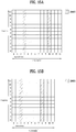
- FIG. 15a illustrates DMRS mapping in the case of a normal cyclic prefix (CP)
- FIG. 15b illustrates DMRS mapping in the case of an extended cyclic prefix (CP).
- the subframe structure designed for the conventional LTE physical uplink shared channel (PUSCH) can be used in V2X communication.
- a DMRS in a subframe with the normal CP may be mapped as shown in FIG. 15a .
- a DMRS may be mapped to orthogonal frequency division multiplexing (OFDM) symbols 3 and 10.
- OFDM orthogonal frequency division multiplexing
- a DMRS in a subframe with the extended CP may be mapped as shown in FIG. 15b .
- a DMRS may be mapped to OFDM symbols 2 and 8.
- an initial frequency offset requirement for V2V communication can be defined as 10 ppm (parts per million).
- a residual frequency offset request may be defined as +/- 0.1 ppm.
- two vehicles may be synchronized with each other based on a signal provided by a shared eNB, vehicle, or other sources.
- a frequency offset difference between the two vehicles may be +/- 0.2 ppm.
- a first vehicle may be synchronized based on a signal from a second vehicle.
- a third vehicle may be synchronized with the first vehicle. That is, since the third vehicle is synchronized across the two vehicles, the synchronization of the third vehicle may be referred to as two-hop synchronization (hop-sync).
- a fourth vehicle may be synchronized with the first vehicle.
- the fourth vehicle may have two-hop synchronization.
- a frequency offset difference between the third and fourth vehicles, which are synchronized with reference to the same first vehicle may be +/- 0.4 ppm.
- a frequency offset difference between two vehicles with three-hop synchronization with respect to the same vehicle may be +/- 0.6 ppm.
- a receiving UE may perform frequency offset correction using the DMRS configured with two columns.
- FIG. 15a there are 5 OFDM symbols between first and second DMRSs.
- a time interval of 0.5 ms may exist between the two DMRSs.
- the UE since the UE may estimate a change in the frequency offset change based on a change in the phase offset, the UE should be able to estimate the phase offset change due to increase in the frequency offset during 0.5 ms.
- Table 1 below shows increase in the phase offset during 0.5 ms according to the center frequency and hop synchronization.
- the current DMRS structure can be used for the frequency offset correction.
- the frequency offset at the center frequency of 2 GHz is +/- 0.6 ppm
- the phase offset value exceeds the value of pi. In this case, the UE may fail to correct the frequency offset.
- the minimum frequency offset of V2V communication can be defined as +/- 0.2 ppm.
- the frequency offset can be assumed to be +/- 0.2 ppm.
- Table 1 a UE operating at the center frequency of 5.9 GHz may not correct the frequency offset using the current DMRS structure (e.g., the structure of FIG. 15a or 15b ).
- Table 2 shows a phase offset (in the unit of radian) varying depending on an interval between the frequency offset and each DMRS (OFDM symbol unit).
- a DMRS when the frequency offset is +/- 0.2 ppm, a DMRS needs to be mapped at an interval consisting of at least five symbols for the frequency offset correction. In addition, when the frequency offset is +/- 0.4 ppm, a DMRS needs to be mapped at an interval consisting of at least two symbols. When the frequency offset is +/-0.6 ppm, a DMRS needs to be mapped at an interval consisting of at least one symbol.
- the present invention proposes a new type of DMRS mapping for enabling frequency offset correction at a high frequency offset.
- a reference signal such as a DMRS
- a DMRS can be mapped at a time interval greater than that of the conventional DMRS or an interval including more OFDM symbols than those of the conventional DMRS.
- the conventional DMRS is mapped at the interval of 6 or 7 symbols within one subframe. If the DMRS interval is reduced, the performance of the frequency offset correction can be improved. However, in this case, since the DMRS is concentrated on specific resources, the channel estimation performance may be degraded.
- an additional DMRS may be mapped to uplink resources. However, in this case, as the DMRS resources increase, the DMRS overhead increases. That is, there may be a problem of lack of resources for data transmission.
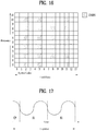
- FIG. 16 illustrates DMRS mapping according to an embodiment of the present invention.
- a method capable of reducing the DMRS interval for the frequency offset correction without increasing the DMRS overhead is required.
- a comb type of DMRS may be used.
- the comb-type DMRS can be mapped to resource elements at the same interval in the frequency domain.
- an additional DMRS may be mapped to two columns except the columns where the current uplink DMRS is mapped. That is, in the comb-type DMRS mapping, the DMRS can be mapped to four OFDM symbols within one subframe.
- the DMRS may be mapped at an interval of two subcarriers in the same column (i.e., same OFDM symbol).
- the comb-type DMRS can be mapped as shown in FIG. 15 . That is, referring to FIG. 16 , the comb-type DMRS is mapped to four OFDM symbols in one subframe at the same interval. In addition, in the same OFDM symbol, the comb-type DMRS can be mapped at an interval of two subcarriers.
- a reference signal e.g., DMRS
- the channel estimation performance can be improved because the reference signal is mapped at the same time interval in the time domain.
- the frequency offset correction performance can also be improved.
- symbols 0 and 13 can be used for automatic gain control (AGC) or Rx/Tx switching.
- FIG. 17 illustrates signal repetition in one symbol according to an embodiment of the present invention.
- the signal When a comb-type reference signal is transmitted, the signal may be repeated in one symbol. As shown in FIG. 17 , a signal S1 is repeated after the cyclic prefix (CP). In this case, it is possible to correct a frequency offset in the same symbol by comparing the repeated signals.
- CP cyclic prefix
- each signal S1 except the CP has N/2 samples, and each sample of the signal is assumed to be s i (where i is a natural number).
- samples with indices from 0 to N/2-1 correspond to samples of the first signal of FIG. 17
- samples with indices from N/2 to N-1 correspond to samples of the second signal of FIG. 17 .
- sample S i is equal to sample S i+N/2 .
- the samples with the same value may be used as a reference for measuring the phase change.
- the transmitted signal sample si goes through the channel and is then received.
- the received sample is defined as r i .
- the frequency offset can be estimated by comparing r i and r i+N/2 .
- Equation 1 atan indicates the arc tangent function.
- the phase offset of signal A can be calculated by determining the arc tangent of imaginary and real values of the signal A.
- the arc tangent value can be divided by N/2.
- the phase offset in each sample interval can be calculated as shown in Equation 2.
- Equation 2 A means the phase offset calculation through comparison of the two same samples r i and r i+N/2 that pass through the channel.
- the phase offset calculated according to Equation 1 may mean a phase value in accordance with increase in each of the sample indices.
- the phase offset value of the received signal may be applied to OFDM symbols adjacent to reference signal OFDM symbols and the reference signal OFDM symbols.
- the phase offset of the received signal can be corrected according to Equation 3 below.
- r i ′ r i exp ⁇ j ⁇ phase offset ⁇ i + 1
- the performance of the phase offset correction of the received signal can be improved.
- the offset calculated based on the reference signal of symbol 2 can be applied to symbols 0, 1, 2, and 3.
- the offset calculated based on the reference signal of symbol 5 can be applied to symbols 4, 5, and 6.
- the offset calculated based on the reference signal of symbol 11 can be applied to symbols 10, 11, 12, and 13. Further, for example, when symbol 0 and/or 13 is used for AGC or Rx/Tx switching, no offset may be applied to symbol 0 and/or 13.
- FIG. 18 illustrates DMRS mapping according to another embodiment of the present invention.
- the DMRS can be mapped as shown in FIG. 18 . That is, referring to FIG. 18 , the reference signal is mapped to symbols 2, 5, 8, and 12, and in the same single symbol, it is mapped at an interval of two subcarriers. The description made with reference to FIGs. 16 and 17 can be equally applied to FIG. 18 .
- the frequency offset correction is performed using the comb-type DMRS mapping
- the following problems may occur.
- two UEs may simultaneously use different frequency subcarriers to transmit data at the same time.
- the above-described frequency offset correction may not be performed.
- the frequency offset correction may be performed in the frequency domain.
- the signal repetition show in FIG. 17 can be used.
- the former repeated signal of FIG. 17 is referred to as a first repeated signal
- the latter repeated signal of FIG. 17 is referred to as a second repeated signal.
- a signal may be generated such that a received first repeated signal is attached to the back of another received first repeated signal, and this signal may be denoted by R 1 . That is, the signal R 1 may be configured with two received first repeated signals.
- a signal may be generated such that a received second repeated signal is attached to the back of another received second repeated signal, and this signal may be denoted by R 2 . That is, the signal R 2 may be configured with two received first repeated signals.
- the signal R 1 may be simply generated by eliminating the second repeated signal from the received signal
- the signal R 2 may be simply generated by eliminating the first repeated signal from the received signal.
- the FFT By performing the FFT on the signals R 1 and R 2 , it is possible to covert these signals into frequency-domain signals.
- the signals can also be converted into frequency-domain signals.
- Signals of corresponding subcarriers corresponding to frequency-domain components of the received signals can be defined as f 1i and f 2i .
- f 1i and f 2i may be configured except unoccupied subcarriers (e.g., subcarriers where the DMRS is not mapped).
- f 1i and f 2i may be signals obtained by estimating even the positions of the unoccupied subcarriers using the reference signal converted into the frequency domain.
- each of f 1i and f 2i may be composed of N samples.
- the frequency offset can be estimated according to Equation 4.
- phase offset atan imag A , real A / 0.5
- Equation 4 atan indicates the arc tangent function.
- the phase offset of signal A can be calculated by determining the arc tangent of imaginary and real values of the signal A.
- the arc tangent value can be divided by a half (0.5) symbol.
- the phase offset in each sample interval can be calculated as shown in Equation 5.
- the phase offset calculated according to Equations 4 and 5 may mean a phase value that increases whenever the symbol index increases by 1.
- the phase offset value of the received signal may be applied to OFDM symbols adjacent to reference signal OFDM symbols and the reference signal OFDM symbols.
- the phase offset of the received signal can be corrected according to Equation 6 below.
- f ki ′ f ki exp ⁇ j ⁇ phase offset ⁇ k + 1
- Equation 6 f ki means a k th frequency-domain signal in order of time.
- the convention uplink DMRS design is used for DMRS design. Details of the conventional uplink DMRS design can be found in clause 5.5 of 3GPP TS 36.211. Specifically, a base sequence, cyclic shift (CS), and orthogonal cover code (OCC) of the conventional uplink DMRS design are modified for the DMRS design of the D2D communication. More specifically, parameters are changed as shown in Table 3 below to design a physical sidelink shared channel (PSSCH) and a physical sidelink control channel (PSCCH) of the D2D communication.
- PSSCH physical sidelink shared channel
- PSCCH physical sidelink control channel
- a DMRS base sequence, cyclic shift (CS), and orthogonal cover code (OCC) can be modified as follows.
- CS cyclic shift
- OCC orthogonal cover code
- n ID RS For example, at least some bits of a transmitting UE ID, a receiving UE ID, a transmitting UE group ID, or a receiving UE group ID may be used for n ID RS .
- This ID may also be referred to as n ID SA .
- the remaining bits of n ID SA may be used for the CS or OCC.
- a DMRS may be randomized or orthogonalized. For example, when 3 bits of n ID SA is used for the CS, n ID SA may be replaced with ⁇ n ID SA / 8 ⁇ mod 30 .
- a new slot number defined in a resource pool may be used for n s .
- a plurality of UEs connected to different eNBs may use the same resource pool through a new slot number defined in each resource pool.
- the slot number may be shared between the UEs through n s .
- n ID SA may be used for f ss .
- a DMRS may be randomized or orthogonalized. For example, 3 bits of n ID SA are used for the CS, n CS , ⁇ may be replaced with ⁇ n ID SA ⁇ mod 8 .
- ⁇ w ⁇ (0) w ⁇ (1) ⁇ may be used as a fixed value for the OCC.
- a method of mapping a DMRS to four symbols can be considered.
- the above-described comb-type mapping can be applied.
- the (comb-type) DMRS may be mapped to all the symbols in the frequency domain where the (conventional) DMRS is mapped.
- the OCC is composed of four sequences.
- the OCC with fixed values may be used.
- the fixed OCC values may be [1 1 1 1], [1 1 -1 -1], [1 -1 1 -1], or [1 -1 -1 1].
- the fixed OCC values can be changed according to a shared channel or synchronization channel.
- a receiving end may be explicitly informed about which comb type is used. For example, when the comb-type DMRS has an interval of two subcarriers, it may be mapped to even-numbered resource elements or odd-numbered resource elements in the same symbol. Thus, information on the resource elements to which the DMRS is mapped may be delivered to the receiving end. Alternatively, the information on the resource elements where the DMRS is mapped may be interconnected to another parameter and then delivered to the receiving end. That is, in the case of the comb-type DMRS, a different mapping scheme related to resource elements may be applied according to n ID SA .
- each of the receiving UE, transmitting UE group, and receiving UE group may use a different DMRS mapping pattern. Thus, it is possible to prevent reference signals from colliding with each other.
- a different RE mapping type may be applied according to the priority of transmission messages.
- the receiving end may determine the priority of the currently received messages by decoding the DMRS.
- the RE mapping type can be changed according to types of transmitting UE.
- the transmitting UE may include a pedestrian, a vehicle, and/or a road side unit (RSU).
- the receiving UE can determine the type of the transmitting UE by decoding the DMRS.
- the RE mapping type can be changed according to types of target UE.
- the receiving UE may also include a pedestrian, a vehicle, and/or a road side unit (RSU).
- the receiving UE can determine the type of the target UE by decoding the DMRS.
- the receiving UE may determine the type of UE that will receive a corresponding message based on the RE mapping type. For example, if the target UE is a vehicle and the receiving UE is a pedestrian, the receiving UE may discard the corresponding message.
- all the current LTE uplink DMRS sequences may not be used.
- a small amount of resources for example, one resource block may be used.
- a 12-length DMRS sequence and a 24-length DMRS sequence have been defined within three resource blocks. If one resource block is used for the comb-type DMRS, a 6-length DMRS sequence is required. In addition, if three resource blocks are used, an 18-length DMRS sequence is required. However, since only the 12-length and 24-length DMRS sequences are defined for the current uplink DMRS sequence, a DMRS sequence for the comb-type DMRS should be defined.
- the LTE uplink DMRS sequence is generated by computers in consideration of the correlation and peak-to-average power ratio (PAPR). Therefore, the current LTE uplink DMRS sequence may be assumed to be a low-correlation sequence.
- a comb-type DMRS sequence using the existing LTE uplink DMRS sequence will be explained.
- the comb-type DMRS sequence may be generated by truncating a part of the LTE uplink DMRS sequence.
- N-length DMRS sequence may be used for the comb-type DMRS.
- N can be assumed to be greater than 0 and smaller than 13.
- the comb-type DMRS sequence may be created by truncating the 12-length DMRS sequence designed for the existing LTE uplink DMRS by N from the head thereof.
- the comb-type DMRS sequence may be created by truncating the 24-length LTE uplink DMRS sequence by N from the head thereof.
- Table 4 shows DMRS sequences in accordance with the current LTE DMRS sequence group (u). [Table 4] u 0 1 2 3 4 5 6 7 8 9 10 11 0 -1 1 3 -3 3 3 1 1 3 1 -3 3 1 1 1 3 3 3 3 -1 1 -3 -3 1 -3 3 2 1 1 -3 -3 -3 -1 -3 -3 1 -3 1 -1 3 -1 1 1 1 1 -1 -3 -3 1 -3 3 -1 4 -1 3 1 -1 1 -1 -3 -1 1 -1 1 3 5 1 -3 3 -1 -1 1 1 -1 -1 3 -3 1 6 -1 3 -3 -3 -3 3 1 -1 3 3 -3 1 7 -3 -1 -1 -1 1 -3 3 -1 1 -3 3 1 8 1 -3 3 1 -1 -1 -1 1 1 3 -1 1 9 1 -3 -1 3 3 -3 1 1 1 10 -1 3
- each row indicates each of the LTE uplink DMRS sequence groups (u from 0 to 29), and each number of the first row indicate an index in the DMRS sequence groups.
- first 6 sequences of the 12-length DMRS sequence may be used as the 6-length DMRs sequence.
- the DMRS sequences having indices from 0 to 5 may be used.
- the comb-type DMRS sequence shown in Table 5 below may be used.
- the comb-type DMRS sequence may have a different length from that of the current LTE uplink DMRS sequence.
- the length of the comb-type DMRS sequence can be assumed to be N.
- N can be greater than 0 and smaller than 13.
- the 12-length DMRS sequence for the LTE uplink DMRS is mapped to all resource elements of one resource block of the frequency band in the frequency domain. In this case, depending on types of comb DMRS, the DMRS sequence may be applied to only the resource elements used for transmitting the DMRS.
- the 24-length DMRS sequence for the LTE uplink DMRS is mapped to all resource elements of two resource blocks of the frequency band in the frequency domain.
- the DMRS sequence may be applied to only the resource elements where the DMRS is actually transmitted as well.
- the comb-type DMRS can be mapped to even-numbered resource elements.
- the DMRS is mapped to six even-numbered resource elements.
- the sequences with even indices (0, 2, 4, 6, 8, and 10) shown in Table 4 may be used as the 6-length comb-type DMRS sequence.
- Table 6 below shows 6-length comb-type DMRS sequences according to the present embodiment.
- the sequence with odd indices (1, 3, 5, 7, 9, and 11) shown in Table 4 may be used as the 6-length comb-type DMRS sequence.
- a pseudo-random sequence may be used to generate the comb-type DMRS sequence like the downlink DMRS sequence.
- Equation 8 c(i) can be determined by the pseudo-random sequence. Since the number of current LTE uplink DMRS sequences is 30 (cf. Table 4), 30 initial values, c init may be designed.
- a control channel resource pool may not be frequency-division multiplexed with a data channel resource pool, that is, frequency division multiplexing (FDM) may not be performed on both the control channel resource pool and data channel resource pool.
- FDM frequency division multiplexing
- a DMRS of scheduling assignment may be determined based on a combination of at least some of a base sequence, cyclic shift (CS), and/or orthogonal cover code (OCC) of the DMRS sequence.
- SA scheduling assignment
- CS cyclic shift
- OCC orthogonal cover code
- the DMRS of the scheduling assignment may be interconnected with that of the data channel. That is, as different DMRS sequences are used in the scheduling assignment to mitigate interference thereof, the DMRS sequence interconnected with the DMRS of the scheduling assignment may be used for data to mitigate interference thereof.
- a specific parameter, "x" may be used to determine the DMRS sequence for the scheduling assignment.
- at least some or all of the DMRS sequence for the data may be determined based on the specific parameter, "x".
- numbering may be performed on y DMRS sequences.
- the numbering of the y DMRS sequences may be performed using a bitmap.
- some or all of the numbered y sequences may be used to determine the DMRS sequence for the data.
- the above-described parameter "x" may be a part of a transmitting UE ID (reception ID or previously configured or signaled ID).
- the parameter "x" may be a value obtained by mapping the CS or OCC to the bitmap.
- the value to which the parameter "x" is mapped can be changed according to the priority of messages.
- the parameter "x" may be used as a message priority value.
- a plurality of CSs and/or OCCs can be applied to either the data or SA.
- a reference signal (e.g., DMRS) can be frequency-division multiplexed with data in the same symbol.
- a reference signal may be mapped to N resource elements in one subframe.
- N reference signal sequences (e.g., DMRS sequences) may be generated.
- the generated reference signal sequences may be mapped to the resource elements in frequency-first order or time-first order. In time-first mapping, the sequences are mapped first along the time axis.
- the sequences may be mapped in the symbol index order of resource elements, where the reference signal is mapped, in a first subcarrier and then mapped in the symbol index order of resource elements, where the reference signal is mapped, in a second subcarrier.
- the sequences are mapped first along the frequency axis.
- the sequences may be mapped in the subcarrier index order of resource elements, where the reference signal is mapped, in a first symbol and then mapped in the subcarrier index order of resource elements, where the reference signal is mapped, in a second symbol.
- the reference signal may not be mapped to, for example, the first and/or last symbols of a subframe.
- FIG. 19 illustrates DMRS mapping according to still another embodiment of the present invention.
- reference signal sequences can be mapped, for example, in the time-first order.
- the reference signal sequences are mapped to subcarrier 3 in the time-first order and then mapped to subcarrier 9 in the time-first order.
- reference signal sequences can be mapped in the frequency-first order.
- the reference signal sequences may be mapped within symbol 0 in ascending order of subcarrier indices (e.g., from subcarrier 3 to subcarrier 9) or in descending order (e.g., from subcarrier 9 to subcarrier 3).
- the reference signal sequences may be mapped first to all resource elements of symbol 0 and then mapped to resource elements of symbol 1.
- c init can be preset as a specific value. For example, when a message that does not require a separate channel like the scheduling assignment and discovery is transmitted, c init can be set as the predetermined value. In addition, for example, c init of the reference signal sequence for data may be determined by an identifier indicated by the scheduling assignment.
- a reference signal can be frequency-division multiplexed with data.
- vertical frequency shift (v-shift) in D2D and V2X communication may be set to be different from the conventional V-shift.
- v-shift vertical frequency shift
- the reference signal is mapped at an interval of six subcarriers in one symbol, and thus a total of six v-shifts can be theoretically applied.
- the V2X communication can be restricted to use only two v-shifts in consideration of the frequency offset.
- the v-shift can be differently configured according to types of message to be transmitted. For example, the v-shift for a periodic message may be set different from that for an event-triggered message. Moreover, the v-shift can also be differently configured according to the sizes of messages. For example, even the same type of messages may have different v-shifts according to the size of each message.
- the v-shift may have a hopping pattern that varies depending on an OFDM symbol and/or subframe.
- the hopping pattern may be preconfigured or determined by an identifier included in the scheduling assignment. If a separate channel is not required like the scheduling assignment and discovery, the hopping pattern of the v-shift can be preconfigured. Alternatively, hopping may not be applied to the v-shift in the case of the scheduling assignment and/or discovery.
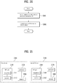
- FIG. 20 is a flowchart illustrating a frequency offset correction method according to an embodiment of the present invention.
- a UE can receive a subframe including a reference signal from a transmitting end [S2001].
- the UE may be a UE that transmits and receives a signal in V2X communication.
- the UE may be a vehicle, a pedestrian, or another transportation units.
- the reference signal may correspond to a DMRS. It can be mapped as described above with reference to FIGs. 15a to 19 .
- the DMRS may be mapped to four symbols in one subframe.
- the symbols where the DMRS is mapped may be equally spaced.
- the DMRS may be mapped in the form of a comb within one symbol.
- the DMRS may be mapped to resource elements with even or odd subframe indices. Information on the resources where the DMRS is mapped may be preconfigured or transmitted from the transmitting end to the receiving end.
- the UE can correct a frequency offset based on the reference signal (S2002). Since signals are repeated in one symbol as described above, the UE can correct the frequency offset by comparing the repeated signals according to the reference signal. In addition, the UE can estimate the frequency offset by estimating a phase offset. Moreover, the UE can compare the repeated signals in the frequency domain by performing an FFT or half-FFT on the repeated signals.
- FIG. 21 schematically illustrates configuration of devices to which the embodiments of the present invention illustrated in FIGs. 1 to 20 may be applied according to an embodiment of the present invention.
- each of a first device 2100 and a second device 2150 which are D2D UEs, includes a radio frequency (RF) unit 2110, 2160, a processor 2120, 2170, and, optionally, a memory 2130, 2180.
- RF radio frequency
- FIG. 21 shows configuration of two D2D UEs, a plurality of D2D UEs may establish a D2D communication environment.
- Each of the RF unit 2130 and 2160 may include a transmitter 2111, 2161 and a receiver 2112, 2162.
- the transmitter 2111 and the receiver 2112 of the first device 2100 may be configured to transmit and receive signals to and from the second device 2150 and other D2D UEs, and the processor 2120 may be functionally connected to the transmitter 2111 and the receiver 2112 to control the transmitter 2111 and the receiver 2112 to transmit and receive signals to and from other devices.
- the first device 2100 and/or the second device 2150 may be an eNB.
- the processor 2120 may perform various kinds of processing on a signal to be transmitted, and then transmit the signal to the transmitter 2111, and process a signal received by the receiver 2112. If necessary, the processor 2120 may store, in the memory 2130, information contained in an exchanged message.
- the first device 2000 may perform the methods of the various embodiments of the present invention described above. For example, each signal and/or message may be transmitted and received using a transmitter and/or receiver of the RF unit, and each operation may be performed under control of the processor.
- the first device 2100 may include various additional elements according to device application type. For example, if the first device 2100 is for intelligent metering, the first device 2100 may include an additional element for power measurement and the like. The operation of power measurement may be under control of the processor 2120 or a separately configured processor (not shown).
- the second device 2150 may be an eNB.
- the transmitter 2161 and receiver 2162 of the eNB may be configured to transmit and receive signals to and from other eNBs, D2D servers, D2D devices, and the processor 2170 may be functionally connected to the transmitter 2161 and receiver 2162 and may be configured to control the process of the transmitter 2161 and the receiver 2162 transmitting and receiving signals to and from other devices.
- the processor 2170 may perform various kinds of processing on a signal to be transmitted, transmit the signal to the transmitter 2161, and process a signal received by the receiver 2162. If necessary, the processor 2170 may store, in the memory 2130, information contained in an exchanged message.
- the eNB 2150 may perform the methods of the various embodiments described above.
- the processors 2120 and 2170 of the first device 2110 and the second device 2150 respectively instruct operations for the first device 2110 and the second device 2150 (for example, control, adjustment, management, etc.).
- Each of the processors 2120 and 2170 may be connected to the memory 2130, 2180 that stores program code and data.
- the memories 2130 and 2180 may be connected to the processors 2120 and 2170 to store operating systems, applications, and general files.
- the processors 2120 and 2170 of the present invention may be referred to as a controller, a microcontroller, a microprocessor, a microcomputer, or the like. Meanwhile, the processors 2120 and 2170 may be implemented by hardware, firmware, software, or a combination thereof. When embodiments of the present invention are implemented using hardware, the processors 2120 and 2170 may include application specific integrated circuits (ASICs), digital signal processors (DSPs), digital signal processing devices (DSPDs), programmable logic devices (PLDs), or field programmable gate arrays (FPGAs).
- ASICs application specific integrated circuits
- DSPs digital signal processors
- DSPDs digital signal processing devices
- PLDs programmable logic devices
- FPGAs field programmable gate arrays
- firmware or software may be configured to include modules, procedures, or functions that perform the functions or operations of the present invention.
- the firmware or software configured to implement the present invention may be provided within the processor or may be stored in the memory and driven by the processor.
Claims (8)
- Procédé pour la correction d'un décalage de fréquence par un équipement utilisateur, UE, (2100) dans une communication de véhicule à véhicule, V2V, le procédé comprenant :la réception (S2001) d'une sous-trame incluant un signal de référence à partir d'une extrémité d'émission ; etla correction (S2002) du décalage de fréquence sur la base du signal de référence,dans lequel le signal de référence est mappé à des éléments de ressource avec des indices de sous-porteuse soit exclusivement pairs soit exclusivement impairs dans chacun de quatre symboles dans la sous-trame,dans lequel la correction du décalage de fréquence comprend la comparaison de signaux répétés, répétés à un intervalle de temps correspondant à la longueur d'un premier symbole parmi les quatre symboles,dans lequel chacun des signaux répétés correspond au signal de référence mappé au premier symbole,dans lequel le signal de référence comprend un signal de référence de démodulation, DMRS, etdans lequel le premier symbole est composé de douze éléments de ressource, ayant chacun un indice de sous-porteuse, dans lequel une première séquence DMRS avec une longueur de 6 est utilisée pour mapper le signal de référence au premier symbole, et dans lequel la première séquence DMRS est constituée d'une partie d'une deuxième séquence DMRS préconfigurée avec une longueur de 12.
- Procédé selon la revendication 1, dans lequel les quatre symboles sont espacés de manière égale dans la sous-trame.
- Procédé selon la revendication 1, dans lequel la comparaison des signaux répétés comprend la comparaison des signaux répétés dans un domaine fréquentiel en effectuant une transformation de Fourier rapide, FFT, ou une demi-FFT sur les signaux répétés.
- Procédé selon la revendication 1, dans lequel le décalage de fréquence corrigé est appliqué au premier symbole et à des symboles adjacents au premier symbole.
- Equipement utilisateur, UE, (2100) pour la correction d'un décalage de fréquence dans une communication de véhicule à véhicule, V2V, l'UE (2100) comprenant :un émetteur-récepteur (2110) ; etun processeur (2120) configuré pour commander l'émetteur-récepteur (2110),dans lequel le processeur (2120) est configuré en outre pour :recevoir, à partir d'une extrémité d'émission, une sous-trame incluant un signal de référence qui est mappé à des éléments de ressource avec des indices de sous-porteuse soit exclusivement pairs soit exclusivement impairs dans chacun de quatre symboles dans la sous-trame ; etcorriger le décalage de fréquence sur la base du signal de référence en comparant des signaux répétés, répétés à un intervalle de temps correspondant à la longueur d'un premier symbole parmi quatre symboles,dans lequel chacun des signaux répétés correspond au signal de référence mappé au premier symbole,dans lequel le signal de référence comprend un signal de référence de démodulation, DMRS, etdans lequel le premier symbole est composé de douze éléments de ressource, ayant chacun un indice de sous-porteuse, dans lequel une première séquence DMRS avec une longueur de 6 est utilisée pour mapper le signal de référence au premier symbole, et dans lequel la première séquence DMRS est constituée d'une partie d'une deuxième séquence DMRS préconfigurée avec une longueur de 12.
- UE (2100) selon la revendication 5, dans lequel les quatre symboles sont espacés de manière égale dans la sous-trame.
- UE (2100) selon la revendication 5, dans lequel le processeur (2120) est configuré en outre pour comparer les signaux répétés dans un domaine fréquentiel en effectuant une transformation de Fourier rapide, FFT, ou une demi-FFT sur les signaux répétés.
- UE (2100) selon la revendication 5, dans lequel le décalage de fréquence corrigé est appliqué au premier symbole et à des symboles adjacents au premier symbole.
Applications Claiming Priority (7)
| Application Number | Priority Date | Filing Date | Title |
|---|---|---|---|
| US201562218550P | 2015-09-14 | 2015-09-14 | |
| US201562222156P | 2015-09-22 | 2015-09-22 | |
| US201562248294P | 2015-10-29 | 2015-10-29 | |
| US201662289372P | 2016-02-01 | 2016-02-01 | |
| US201662316573P | 2016-04-01 | 2016-04-01 | |
| US201662334442P | 2016-05-10 | 2016-05-10 | |
| PCT/KR2016/010356 WO2017048064A1 (fr) | 2015-09-14 | 2016-09-13 | Procédé de correction de décalage de fréquence dans une communication v2v, et dispositif associé |
Publications (3)
| Publication Number | Publication Date |
|---|---|
| EP3352404A1 EP3352404A1 (fr) | 2018-07-25 |
| EP3352404A4 EP3352404A4 (fr) | 2019-05-08 |
| EP3352404B1 true EP3352404B1 (fr) | 2020-12-23 |
Family
ID=58289361
Family Applications (1)
| Application Number | Title | Priority Date | Filing Date |
|---|---|---|---|
| EP16846885.8A Active EP3352404B1 (fr) | 2015-09-14 | 2016-09-13 | Procédé de correction de décalage de fréquence dans une communication v2v, et dispositif associé |
Country Status (2)
| Country | Link |
|---|---|
| EP (1) | EP3352404B1 (fr) |
| WO (1) | WO2017048064A1 (fr) |
Families Citing this family (11)
| Publication number | Priority date | Publication date | Assignee | Title |
|---|---|---|---|---|
| US11219025B2 (en) | 2017-04-24 | 2022-01-04 | Lg Electronics Inc. | Method by which D2D terminal transmits RS for PDoA in wireless communication system and device therefor |
| US10736074B2 (en) | 2017-07-31 | 2020-08-04 | Qualcomm Incorporated | Systems and methods to facilitate location determination by beamforming of a positioning reference signal |
| EP4102761A1 (fr) | 2018-01-22 | 2022-12-14 | Guangdong Oppo Mobile Telecommunications Corp., Ltd. | Procédé de traitement d'informations, dispositif et support d'informations |
| CN110166198A (zh) | 2018-02-12 | 2019-08-23 | 北京三星通信技术研究有限公司 | 旁路信号发送方法和设备 |
| WO2019190273A1 (fr) * | 2018-03-30 | 2019-10-03 | 엘지전자 주식회사 | Procédé d'émission ou de réception de signal de liaison latérale par un terminal dans un système de communication sans fil prenant en charge une liaison latérale, et appareil associé |
| US10547941B1 (en) | 2019-01-16 | 2020-01-28 | Ford Global Technologies, Llc | Vehicle acoustic transducer operation |
| US11777764B2 (en) | 2019-03-28 | 2023-10-03 | Qualcomm Incorporated | Sounding reference signal waveform design for wireless communications |
| US11239967B2 (en) | 2019-05-02 | 2022-02-01 | Qualcomm Incorporated | Patterns for reference signals used for positioning in a wireless communications system |
| US11082183B2 (en) | 2019-09-16 | 2021-08-03 | Qualcomm Incorporated | Comb shift design |
| EP3820101A1 (fr) * | 2019-11-07 | 2021-05-12 | FRAUNHOFER-GESELLSCHAFT zur Förderung der angewandten Forschung e.V. | Annulation ou réduction de l'ambiguïté/du repliement pour les signaux de référence décalés |
| CN115316026A (zh) * | 2020-03-31 | 2022-11-08 | 华为技术有限公司 | 传输参考信号的方法和装置 |
Family Cites Families (6)
| Publication number | Priority date | Publication date | Assignee | Title |
|---|---|---|---|---|
| US7813437B2 (en) * | 2007-09-13 | 2010-10-12 | Beceem Communications Inc. | Estimating frequency offset at a subscriber station receiver |
| MA33907B1 (fr) * | 2010-01-20 | 2013-01-02 | Ericsson Telefon Ab L M | Procédé de mappage de ports d'antenne et dispositif pour signaux de reference de demodulation |
| US8416759B1 (en) * | 2010-07-30 | 2013-04-09 | Applied Micro Circuits Corporations | Carrier frequency offset and doppler frequency estimation and correction for OFDMA and SC-FDMA |
| US20130343477A9 (en) * | 2011-11-04 | 2013-12-26 | Research In Motion Limited | PUSCH Reference Signal Design for High Doppler Frequency |
| US8971465B2 (en) * | 2012-03-30 | 2015-03-03 | Qualcomm Incorporated | Receiver-side estimation of and compensation for signal impairments |
| CA2872866A1 (fr) * | 2012-05-11 | 2013-11-14 | Optis Wireless Technology, Llc | Modele de signal de reference pour configurations de sous-trames speciales |
-
2016
- 2016-09-13 WO PCT/KR2016/010356 patent/WO2017048064A1/fr active Application Filing
- 2016-09-13 EP EP16846885.8A patent/EP3352404B1/fr active Active
Non-Patent Citations (1)
| Title |
|---|
| None * |
Also Published As
| Publication number | Publication date |
|---|---|
| EP3352404A1 (fr) | 2018-07-25 |
| WO2017048064A1 (fr) | 2017-03-23 |
| EP3352404A4 (fr) | 2019-05-08 |
Similar Documents
| Publication | Publication Date | Title |
|---|---|---|
| EP3358775B1 (fr) | Procédé et appareil de transmission de signaux de référence durant une communication de type d2d | |
| EP3352404B1 (fr) | Procédé de correction de décalage de fréquence dans une communication v2v, et dispositif associé | |
| US11700641B2 (en) | Random access procedure performing method in wireless communication system, and apparatus therefor | |
| US11026217B2 (en) | Sidelink signal transmission/reception method of UE in wireless communication system | |
| US11902807B2 (en) | Method and apparatus for measuring and transmitting CR by user equipment in wireless communication system | |
| US10594455B2 (en) | Method for transmitting reference signal in V2X communication and apparatus therefor | |
| CN109891959B (zh) | 通过应用偏移来发送d2d信号的方法和设备 | |
| US11115958B2 (en) | Method whereby terminal transmits and receives sidelink signals in wireless communication system | |
| US10693699B2 (en) | Method and terminal for transmitting synchronization signal in V2X communication | |
| JP6899427B2 (ja) | 無線通信システムにおいて端末の測定によるリソース選択及びデータ伝送方法及び装置 | |
| EP3442285B1 (fr) | Procédé pour transmettre et recevoir un signal de liaison latérale par l'intermédiaire d'un ue dans un système de communications sans fil | |
| US11057260B2 (en) | Method for electricity measurement for V2V communications in wireless communication system, and device for same | |
| EP3402112B1 (fr) | Communication fiable et stable de type v2x | |
| US20190281405A1 (en) | Method and device for selecting resources and transmitting pssch in wireless communication system | |
| US11722262B2 (en) | Method and apparatus for transmitting feedback by terminal receiving signal from another terminal in wireless communication system | |
| US20210160819A1 (en) | Method by which terminal simultaneously transmits messages in at least two carriers in wireless communication system supporting device to device communication, and apparatus therefor | |
| EP3402276B1 (fr) | Procédé et dispositif permettant de transmettre des données et des informations de commande d'un terminal dans un système de communication sans fil |
Legal Events
| Date | Code | Title | Description |
|---|---|---|---|
| STAA | Information on the status of an ep patent application or granted ep patent |
Free format text: STATUS: THE INTERNATIONAL PUBLICATION HAS BEEN MADE |
|
| PUAI | Public reference made under article 153(3) epc to a published international application that has entered the european phase |
Free format text: ORIGINAL CODE: 0009012 |
|
| STAA | Information on the status of an ep patent application or granted ep patent |
Free format text: STATUS: REQUEST FOR EXAMINATION WAS MADE |
|
| 17P | Request for examination filed |
Effective date: 20180413 |
|
| AK | Designated contracting states |
Kind code of ref document: A1 Designated state(s): AL AT BE BG CH CY CZ DE DK EE ES FI FR GB GR HR HU IE IS IT LI LT LU LV MC MK MT NL NO PL PT RO RS SE SI SK SM TR |
|
| AX | Request for extension of the european patent |
Extension state: BA ME |
|
| DAV | Request for validation of the european patent (deleted) | ||
| DAX | Request for extension of the european patent (deleted) | ||
| A4 | Supplementary search report drawn up and despatched |
Effective date: 20190404 |
|
| RIC1 | Information provided on ipc code assigned before grant |
Ipc: H04W 84/00 20090101ALI20190329BHEP Ipc: H04L 5/00 20060101AFI20190329BHEP Ipc: H04L 27/26 20060101ALI20190329BHEP Ipc: H04L 27/00 20060101ALI20190329BHEP |
|
| GRAP | Despatch of communication of intention to grant a patent |
Free format text: ORIGINAL CODE: EPIDOSNIGR1 |
|
| STAA | Information on the status of an ep patent application or granted ep patent |
Free format text: STATUS: GRANT OF PATENT IS INTENDED |
|
| INTG | Intention to grant announced |
Effective date: 20200709 |
|
| GRAS | Grant fee paid |
Free format text: ORIGINAL CODE: EPIDOSNIGR3 |
|
| GRAA | (expected) grant |
Free format text: ORIGINAL CODE: 0009210 |
|
| STAA | Information on the status of an ep patent application or granted ep patent |
Free format text: STATUS: THE PATENT HAS BEEN GRANTED |
|
| AK | Designated contracting states |
Kind code of ref document: B1 Designated state(s): AL AT BE BG CH CY CZ DE DK EE ES FI FR GB GR HR HU IE IS IT LI LT LU LV MC MK MT NL NO PL PT RO RS SE SI SK SM TR |
|
| REG | Reference to a national code |
Ref country code: GB Ref legal event code: FG4D |
|
| REG | Reference to a national code |
Ref country code: DE Ref legal event code: R096 Ref document number: 602016050365 Country of ref document: DE |
|
| REG | Reference to a national code |
Ref country code: AT Ref legal event code: REF Ref document number: 1348754 Country of ref document: AT Kind code of ref document: T Effective date: 20210115 |
|
| REG | Reference to a national code |
Ref country code: IE Ref legal event code: FG4D |
|
| PG25 | Lapsed in a contracting state [announced via postgrant information from national office to epo] |
Ref country code: GR Free format text: LAPSE BECAUSE OF FAILURE TO SUBMIT A TRANSLATION OF THE DESCRIPTION OR TO PAY THE FEE WITHIN THE PRESCRIBED TIME-LIMIT Effective date: 20210324 Ref country code: FI Free format text: LAPSE BECAUSE OF FAILURE TO SUBMIT A TRANSLATION OF THE DESCRIPTION OR TO PAY THE FEE WITHIN THE PRESCRIBED TIME-LIMIT Effective date: 20201223 Ref country code: NO Free format text: LAPSE BECAUSE OF FAILURE TO SUBMIT A TRANSLATION OF THE DESCRIPTION OR TO PAY THE FEE WITHIN THE PRESCRIBED TIME-LIMIT Effective date: 20210323 Ref country code: RS Free format text: LAPSE BECAUSE OF FAILURE TO SUBMIT A TRANSLATION OF THE DESCRIPTION OR TO PAY THE FEE WITHIN THE PRESCRIBED TIME-LIMIT Effective date: 20201223 |
|
| REG | Reference to a national code |
Ref country code: AT Ref legal event code: MK05 Ref document number: 1348754 Country of ref document: AT Kind code of ref document: T Effective date: 20201223 |
|
| REG | Reference to a national code |
Ref country code: NL Ref legal event code: MP Effective date: 20201223 |
|
| PG25 | Lapsed in a contracting state [announced via postgrant information from national office to epo] |
Ref country code: SE Free format text: LAPSE BECAUSE OF FAILURE TO SUBMIT A TRANSLATION OF THE DESCRIPTION OR TO PAY THE FEE WITHIN THE PRESCRIBED TIME-LIMIT Effective date: 20201223 Ref country code: LV Free format text: LAPSE BECAUSE OF FAILURE TO SUBMIT A TRANSLATION OF THE DESCRIPTION OR TO PAY THE FEE WITHIN THE PRESCRIBED TIME-LIMIT Effective date: 20201223 Ref country code: BG Free format text: LAPSE BECAUSE OF FAILURE TO SUBMIT A TRANSLATION OF THE DESCRIPTION OR TO PAY THE FEE WITHIN THE PRESCRIBED TIME-LIMIT Effective date: 20210323 |
|
| PG25 | Lapsed in a contracting state [announced via postgrant information from national office to epo] |
Ref country code: NL Free format text: LAPSE BECAUSE OF FAILURE TO SUBMIT A TRANSLATION OF THE DESCRIPTION OR TO PAY THE FEE WITHIN THE PRESCRIBED TIME-LIMIT Effective date: 20201223 Ref country code: HR Free format text: LAPSE BECAUSE OF FAILURE TO SUBMIT A TRANSLATION OF THE DESCRIPTION OR TO PAY THE FEE WITHIN THE PRESCRIBED TIME-LIMIT Effective date: 20201223 |
|
| REG | Reference to a national code |
Ref country code: LT Ref legal event code: MG9D |
|
| PG25 | Lapsed in a contracting state [announced via postgrant information from national office to epo] |
Ref country code: SM Free format text: LAPSE BECAUSE OF FAILURE TO SUBMIT A TRANSLATION OF THE DESCRIPTION OR TO PAY THE FEE WITHIN THE PRESCRIBED TIME-LIMIT Effective date: 20201223 Ref country code: LT Free format text: LAPSE BECAUSE OF FAILURE TO SUBMIT A TRANSLATION OF THE DESCRIPTION OR TO PAY THE FEE WITHIN THE PRESCRIBED TIME-LIMIT Effective date: 20201223 Ref country code: CZ Free format text: LAPSE BECAUSE OF FAILURE TO SUBMIT A TRANSLATION OF THE DESCRIPTION OR TO PAY THE FEE WITHIN THE PRESCRIBED TIME-LIMIT Effective date: 20201223 Ref country code: EE Free format text: LAPSE BECAUSE OF FAILURE TO SUBMIT A TRANSLATION OF THE DESCRIPTION OR TO PAY THE FEE WITHIN THE PRESCRIBED TIME-LIMIT Effective date: 20201223 Ref country code: RO Free format text: LAPSE BECAUSE OF FAILURE TO SUBMIT A TRANSLATION OF THE DESCRIPTION OR TO PAY THE FEE WITHIN THE PRESCRIBED TIME-LIMIT Effective date: 20201223 Ref country code: PT Free format text: LAPSE BECAUSE OF FAILURE TO SUBMIT A TRANSLATION OF THE DESCRIPTION OR TO PAY THE FEE WITHIN THE PRESCRIBED TIME-LIMIT Effective date: 20210423 Ref country code: SK Free format text: LAPSE BECAUSE OF FAILURE TO SUBMIT A TRANSLATION OF THE DESCRIPTION OR TO PAY THE FEE WITHIN THE PRESCRIBED TIME-LIMIT Effective date: 20201223 |
|
| PG25 | Lapsed in a contracting state [announced via postgrant information from national office to epo] |
Ref country code: PL Free format text: LAPSE BECAUSE OF FAILURE TO SUBMIT A TRANSLATION OF THE DESCRIPTION OR TO PAY THE FEE WITHIN THE PRESCRIBED TIME-LIMIT Effective date: 20201223 Ref country code: AT Free format text: LAPSE BECAUSE OF FAILURE TO SUBMIT A TRANSLATION OF THE DESCRIPTION OR TO PAY THE FEE WITHIN THE PRESCRIBED TIME-LIMIT Effective date: 20201223 |
|
| REG | Reference to a national code |
Ref country code: DE Ref legal event code: R097 Ref document number: 602016050365 Country of ref document: DE |
|
| PG25 | Lapsed in a contracting state [announced via postgrant information from national office to epo] |
Ref country code: IS Free format text: LAPSE BECAUSE OF FAILURE TO SUBMIT A TRANSLATION OF THE DESCRIPTION OR TO PAY THE FEE WITHIN THE PRESCRIBED TIME-LIMIT Effective date: 20210423 |
|
| PG25 | Lapsed in a contracting state [announced via postgrant information from national office to epo] |
Ref country code: AL Free format text: LAPSE BECAUSE OF FAILURE TO SUBMIT A TRANSLATION OF THE DESCRIPTION OR TO PAY THE FEE WITHIN THE PRESCRIBED TIME-LIMIT Effective date: 20201223 Ref country code: IT Free format text: LAPSE BECAUSE OF FAILURE TO SUBMIT A TRANSLATION OF THE DESCRIPTION OR TO PAY THE FEE WITHIN THE PRESCRIBED TIME-LIMIT Effective date: 20201223 |
|
| PLBE | No opposition filed within time limit |
Free format text: ORIGINAL CODE: 0009261 |
|
| STAA | Information on the status of an ep patent application or granted ep patent |
Free format text: STATUS: NO OPPOSITION FILED WITHIN TIME LIMIT |
|
| PG25 | Lapsed in a contracting state [announced via postgrant information from national office to epo] |
Ref country code: DK Free format text: LAPSE BECAUSE OF FAILURE TO SUBMIT A TRANSLATION OF THE DESCRIPTION OR TO PAY THE FEE WITHIN THE PRESCRIBED TIME-LIMIT Effective date: 20201223 |
|
| 26N | No opposition filed |
Effective date: 20210924 |
|
| PG25 | Lapsed in a contracting state [announced via postgrant information from national office to epo] |
Ref country code: ES Free format text: LAPSE BECAUSE OF FAILURE TO SUBMIT A TRANSLATION OF THE DESCRIPTION OR TO PAY THE FEE WITHIN THE PRESCRIBED TIME-LIMIT Effective date: 20201223 |
|
| PG25 | Lapsed in a contracting state [announced via postgrant information from national office to epo] |
Ref country code: SI Free format text: LAPSE BECAUSE OF FAILURE TO SUBMIT A TRANSLATION OF THE DESCRIPTION OR TO PAY THE FEE WITHIN THE PRESCRIBED TIME-LIMIT Effective date: 20201223 |
|
| REG | Reference to a national code |
Ref country code: CH Ref legal event code: PL |
|
| REG | Reference to a national code |
Ref country code: BE Ref legal event code: MM Effective date: 20210930 |
|
| GBPC | Gb: european patent ceased through non-payment of renewal fee |
Effective date: 20210913 |
|
| PG25 | Lapsed in a contracting state [announced via postgrant information from national office to epo] |
Ref country code: IS Free format text: LAPSE BECAUSE OF FAILURE TO SUBMIT A TRANSLATION OF THE DESCRIPTION OR TO PAY THE FEE WITHIN THE PRESCRIBED TIME-LIMIT Effective date: 20210423 Ref country code: MC Free format text: LAPSE BECAUSE OF FAILURE TO SUBMIT A TRANSLATION OF THE DESCRIPTION OR TO PAY THE FEE WITHIN THE PRESCRIBED TIME-LIMIT Effective date: 20201223 |
|
| PG25 | Lapsed in a contracting state [announced via postgrant information from national office to epo] |
Ref country code: LU Free format text: LAPSE BECAUSE OF NON-PAYMENT OF DUE FEES Effective date: 20210913 Ref country code: IE Free format text: LAPSE BECAUSE OF NON-PAYMENT OF DUE FEES Effective date: 20210913 Ref country code: GB Free format text: LAPSE BECAUSE OF NON-PAYMENT OF DUE FEES Effective date: 20210913 Ref country code: FR Free format text: LAPSE BECAUSE OF NON-PAYMENT OF DUE FEES Effective date: 20210930 Ref country code: BE Free format text: LAPSE BECAUSE OF NON-PAYMENT OF DUE FEES Effective date: 20210930 |
|
| PG25 | Lapsed in a contracting state [announced via postgrant information from national office to epo] |
Ref country code: LI Free format text: LAPSE BECAUSE OF NON-PAYMENT OF DUE FEES Effective date: 20210930 Ref country code: CH Free format text: LAPSE BECAUSE OF NON-PAYMENT OF DUE FEES Effective date: 20210930 |
|
| PG25 | Lapsed in a contracting state [announced via postgrant information from national office to epo] |
Ref country code: HU Free format text: LAPSE BECAUSE OF FAILURE TO SUBMIT A TRANSLATION OF THE DESCRIPTION OR TO PAY THE FEE WITHIN THE PRESCRIBED TIME-LIMIT; INVALID AB INITIO Effective date: 20160913 |
|
| PG25 | Lapsed in a contracting state [announced via postgrant information from national office to epo] |
Ref country code: CY Free format text: LAPSE BECAUSE OF FAILURE TO SUBMIT A TRANSLATION OF THE DESCRIPTION OR TO PAY THE FEE WITHIN THE PRESCRIBED TIME-LIMIT Effective date: 20201223 |
|
| PGFP | Annual fee paid to national office [announced via postgrant information from national office to epo] |
Ref country code: DE Payment date: 20230807 Year of fee payment: 8 |