EP3352340A1 - Stator coil, method for manufacturing stator, and dynamo-electric machine - Google Patents
Stator coil, method for manufacturing stator, and dynamo-electric machine Download PDFInfo
- Publication number
- EP3352340A1 EP3352340A1 EP16878971.7A EP16878971A EP3352340A1 EP 3352340 A1 EP3352340 A1 EP 3352340A1 EP 16878971 A EP16878971 A EP 16878971A EP 3352340 A1 EP3352340 A1 EP 3352340A1
- Authority
- EP
- European Patent Office
- Prior art keywords
- coil
- slot
- coil portion
- stator core
- radially inner
- Prior art date
- Legal status (The legal status is an assumption and is not a legal conclusion. Google has not performed a legal analysis and makes no representation as to the accuracy of the status listed.)
- Withdrawn
Links
- 238000004519 manufacturing process Methods 0.000 title claims description 25
- 238000000034 method Methods 0.000 title claims description 23
- 238000004804 winding Methods 0.000 claims abstract description 91
- 239000002356 single layer Substances 0.000 claims abstract description 52
- 239000010410 layer Substances 0.000 claims abstract description 43
- 239000004020 conductor Substances 0.000 description 67
- 230000000694 effects Effects 0.000 description 9
- 230000004907 flux Effects 0.000 description 9
- 230000006866 deterioration Effects 0.000 description 7
- XEEYBQQBJWHFJM-UHFFFAOYSA-N Iron Chemical group [Fe] XEEYBQQBJWHFJM-UHFFFAOYSA-N 0.000 description 6
- 230000002093 peripheral effect Effects 0.000 description 4
- 230000002452 interceptive effect Effects 0.000 description 3
- 229910052742 iron Inorganic materials 0.000 description 3
- 238000006243 chemical reaction Methods 0.000 description 2
- 238000010586 diagram Methods 0.000 description 1
- 238000012986 modification Methods 0.000 description 1
- 230000004048 modification Effects 0.000 description 1
- 230000001151 other effect Effects 0.000 description 1
Images




Classifications
-
- H—ELECTRICITY
- H02—GENERATION; CONVERSION OR DISTRIBUTION OF ELECTRIC POWER
- H02K—DYNAMO-ELECTRIC MACHINES
- H02K3/00—Details of windings
- H02K3/04—Windings characterised by the conductor shape, form or construction, e.g. with bar conductors
- H02K3/28—Layout of windings or of connections between windings
-
- H—ELECTRICITY
- H02—GENERATION; CONVERSION OR DISTRIBUTION OF ELECTRIC POWER
- H02K—DYNAMO-ELECTRIC MACHINES
- H02K1/00—Details of the magnetic circuit
- H02K1/06—Details of the magnetic circuit characterised by the shape, form or construction
- H02K1/12—Stationary parts of the magnetic circuit
- H02K1/16—Stator cores with slots for windings
- H02K1/165—Shape, form or location of the slots
-
- H—ELECTRICITY
- H02—GENERATION; CONVERSION OR DISTRIBUTION OF ELECTRIC POWER
- H02K—DYNAMO-ELECTRIC MACHINES
- H02K1/00—Details of the magnetic circuit
- H02K1/06—Details of the magnetic circuit characterised by the shape, form or construction
- H02K1/22—Rotating parts of the magnetic circuit
- H02K1/27—Rotor cores with permanent magnets
- H02K1/2706—Inner rotors
- H02K1/272—Inner rotors the magnetisation axis of the magnets being perpendicular to the rotor axis
- H02K1/274—Inner rotors the magnetisation axis of the magnets being perpendicular to the rotor axis the rotor consisting of two or more circumferentially positioned magnets
- H02K1/2753—Inner rotors the magnetisation axis of the magnets being perpendicular to the rotor axis the rotor consisting of two or more circumferentially positioned magnets the rotor consisting of magnets or groups of magnets arranged with alternating polarity
-
- H—ELECTRICITY
- H02—GENERATION; CONVERSION OR DISTRIBUTION OF ELECTRIC POWER
- H02K—DYNAMO-ELECTRIC MACHINES
- H02K15/00—Processes or apparatus specially adapted for manufacturing, assembling, maintaining or repairing of dynamo-electric machines
- H02K15/02—Processes or apparatus specially adapted for manufacturing, assembling, maintaining or repairing of dynamo-electric machines of stator or rotor bodies
- H02K15/021—Magnetic cores
-
- H—ELECTRICITY
- H02—GENERATION; CONVERSION OR DISTRIBUTION OF ELECTRIC POWER
- H02K—DYNAMO-ELECTRIC MACHINES
- H02K15/00—Processes or apparatus specially adapted for manufacturing, assembling, maintaining or repairing of dynamo-electric machines
- H02K15/02—Processes or apparatus specially adapted for manufacturing, assembling, maintaining or repairing of dynamo-electric machines of stator or rotor bodies
- H02K15/03—Processes or apparatus specially adapted for manufacturing, assembling, maintaining or repairing of dynamo-electric machines of stator or rotor bodies having permanent magnets
-
- H—ELECTRICITY
- H02—GENERATION; CONVERSION OR DISTRIBUTION OF ELECTRIC POWER
- H02K—DYNAMO-ELECTRIC MACHINES
- H02K15/00—Processes or apparatus specially adapted for manufacturing, assembling, maintaining or repairing of dynamo-electric machines
- H02K15/04—Processes or apparatus specially adapted for manufacturing, assembling, maintaining or repairing of dynamo-electric machines of windings prior to their mounting into the machines
- H02K15/043—Processes or apparatus specially adapted for manufacturing, assembling, maintaining or repairing of dynamo-electric machines of windings prior to their mounting into the machines winding flat conductive wires or sheets
- H02K15/0432—Distributed windings
-
- H—ELECTRICITY
- H02—GENERATION; CONVERSION OR DISTRIBUTION OF ELECTRIC POWER
- H02K—DYNAMO-ELECTRIC MACHINES
- H02K15/00—Processes or apparatus specially adapted for manufacturing, assembling, maintaining or repairing of dynamo-electric machines
- H02K15/06—Embedding prefabricated windings in the machines
- H02K15/062—Windings in slots; Salient pole windings
- H02K15/065—Windings consisting of complete sections, e.g. coils or waves
-
- H—ELECTRICITY
- H02—GENERATION; CONVERSION OR DISTRIBUTION OF ELECTRIC POWER
- H02K—DYNAMO-ELECTRIC MACHINES
- H02K15/00—Processes or apparatus specially adapted for manufacturing, assembling, maintaining or repairing of dynamo-electric machines
- H02K15/06—Embedding prefabricated windings in the machines
- H02K15/062—Windings in slots; Salient pole windings
- H02K15/065—Windings consisting of complete sections, e.g. coils or waves
- H02K15/066—Windings consisting of complete sections, e.g. coils or waves inserted perpendicularly to the axis of the slots or inter-polar channels
-
- H—ELECTRICITY
- H02—GENERATION; CONVERSION OR DISTRIBUTION OF ELECTRIC POWER
- H02K—DYNAMO-ELECTRIC MACHINES
- H02K23/00—DC commutator motors or generators having mechanical commutator; Universal AC/DC commutator motors
- H02K23/26—DC commutator motors or generators having mechanical commutator; Universal AC/DC commutator motors characterised by the armature windings
- H02K23/30—DC commutator motors or generators having mechanical commutator; Universal AC/DC commutator motors characterised by the armature windings having lap or loop windings
-
- H—ELECTRICITY
- H02—GENERATION; CONVERSION OR DISTRIBUTION OF ELECTRIC POWER
- H02K—DYNAMO-ELECTRIC MACHINES
- H02K3/00—Details of windings
- H02K3/04—Windings characterised by the conductor shape, form or construction, e.g. with bar conductors
- H02K3/12—Windings characterised by the conductor shape, form or construction, e.g. with bar conductors arranged in slots
-
- H—ELECTRICITY
- H02—GENERATION; CONVERSION OR DISTRIBUTION OF ELECTRIC POWER
- H02K—DYNAMO-ELECTRIC MACHINES
- H02K1/00—Details of the magnetic circuit
- H02K1/06—Details of the magnetic circuit characterised by the shape, form or construction
- H02K1/12—Stationary parts of the magnetic circuit
- H02K1/14—Stator cores with salient poles
- H02K1/146—Stator cores with salient poles consisting of a generally annular yoke with salient poles
- H02K1/148—Sectional cores
Definitions
- the present invention relates to a stator coil, a method for manufacturing a stator, and a rotating electrical machine.
- a rotating electrical machine including double-layer lap winding coils, in each of which one of a pair of slot-housed portions of the coil that are arranged in slots is arranged on a radially outer side of the slot and the other of the pair of slot-housed portions is arranged on a radially inner side of the slot.
- Such a rotating electrical machine is disclosed in, for example, Japanese Patent Application Publication No. 2009-195004 ( JP 2009-195004 A ).
- the slot-housed portion of one double-layer lap winding coil out of the two double-layer lap winding coils that are arranged adjacent to each other is arranged on the radially outer side of the slot, and the slot-housed portion of the other double-layer lap winding coil is arranged on the radially inner side of the same slot as that in which the slot-housed portion of the one double-layer lap winding coil is arranged.
- the double-layer lap winding coils are arranged in all of the plurality of slots.
- the slot-housed portion of the double-layer lap winding coil to be finally arranged be arranged in the slot in a state in which the slot-housed portion of the double-layer lap winding coil that is first arranged is temporarily removed from the slot, and then the slot-housed portion of the double-layer lap winding coil that is first arranged and temporarily removed from the slot be arranged in the slot again.
- One lap winding coil that is first arranged in a stator core (slots) and another lap winding coil that is finally arranged in the stator core are structured as single-layer lap winding coils.
- the one single-layer lap winding coil is first arranged on deep sides of the slots, the double-layer lap winding coils are arranged in the stator core, and then, that other single-layer lap winding coil is finally arranged on shallow sides of the slots.
- the one single-layer lap winding coil and the other single-layer lap winding coil are routed together (routing is changed) after the one single-layer lap winding coil and that other single-layer lap winding coil are arranged in the stator core in order to prevent the deterioration of the balance of flux linkage.
- the one single-layer lap winding coil and that other single-layer lap winding coil are structured to be connected together so as to have a balance of flux linkage similar to that of the double-layer lap winding coil.
- Patent Document 1 Japanese Patent Application Publication No. 2009-195004 ( JP 2009-195004 A )
- stator coil having the structure described above has a problem in terms of difficulty in achieving mechanization (automation) of the operation of arranging the stator coil in the slots while the increase in the size of the stator coil (rotating electrical machine) is prevented.
- the present invention has been made to solve the problem described above, and it is one object of the present invention to provide a stator coil, a method for manufacturing a stator, and a rotating electrical machine, in which an operation of arranging the stator coil in slots can be mechanized (automated) easily preventing an increase in the size of the stator coil (rotating electrical machine).
- a stator coil is a coil to be arranged in a stator core.
- the coil includes a first coil portion formed of a single-layer lap winding coil including a pair of first slot-housed portions to be respectively arranged on a radially outer side of a first slot and on a radially outer side of a second slot, a second coil portion continuously connected to an other-side end of a first connecting wire portion having a one-side end continuously connected to the first coil portion, and formed of a single-layer lap winding coil including a pair of second slot-housed portions, one of which is arranged on a radially inner side of the first slot and the other of which is arranged on a radially inner side of a third slot different from the first slot and the second slot, and a third coil portion group including a plurality of third coil portions each formed of a double-layer lap winding coil.
- a third slot-housed portion at a one-side end of the third coil portion group in a circumferential direction is arranged on a radially inner side of the second slot, and a third slot-housed portion at an other-side end of the third coil portion group in the circumferential direction is arranged on a radially outer side of the third slot.
- stator coil according to the first aspect of the present invention with the structure described above, for example, when the slots are open to a radially outer side of the stator core, it is possible to first arrange the second coil portion formed of the single-layer lap winding coil in the stator core in a state in which the first coil portion is retreated to the outside of the stator core (for example, a radially inner side of the stator core), arrange the third coil portion group including the plurality of third coil portions each formed of the double-layer lap winding coil in the stator core, and finally arrange, in the stator core, the first coil portion that is arranged on (retreated to) the outside of the stator core.
- stator coil rotating electrical machine
- the increase in the size of the stator coil (rotating electrical machine) can be prevented.
- the operation of arranging the stator coil in the slots can be mechanized (automated) easily while preventing the increase in the size of the stator coil (rotating electrical machine).
- a method for manufacturing a stator according to a second aspect of the present invention is a method for manufacturing a stator including a stator core having a first slot, a second slot, and a third slot that are different slots.
- the method includes arranging, in a state in which one of a first coil portion and a second coil portion is retreated to an outside of the stator core, the other of the first coil portion and the second coil portion in the stator core, the first coil portion being formed of a single-layer lap winding coil including a pair of first slot-housed portions to be respectively arranged on a radially outer side of the first slot and on a radially outer side of the second slot of the stator core, the second coil portion being continuously connected to an other-side end of a first connecting wire portion having a one-side end continuously connected to the first coil portion, and formed of a single-layer lap winding coil including a pair of second slot-housed portions, one of which is arranged on a radially inner side of the first slot and
- a rotating electrical machine includes a rotor core provided with a permanent magnet, a stator core arranged so as to face the rotor core in a radial direction, and having a first slot, a second slot, and a third slot that are different slots, and a coil arranged in the stator core.
- the coil includes a first coil portion formed of a single-layer lap winding coil including a pair of first slot-housed portions respectively arranged on a radially outer side of the first slot and on a radially outer side of the second slot, a second coil portion continuously connected to an other-side end of a first connecting wire portion having a one-side end continuously connected to the first coil portion, and formed of a single-layer lap winding coil including a pair of second slot-housed portions, one of which is arranged on a radially inner side of the first slot and the other of which is arranged on a radially inner side of the third slot different from the first slot and the second slot, and a third coil portion group including a plurality of third coil portions each formed of a double-layer lap winding coil.
- a third slot-housed portion at a one-side end of the third coil portion group in a circumferential direction is arranged on a radially inner side of the second slot, and a third slot-housed portion at an other-side end of the third coil portion group in the circumferential direction is arranged on a radially outer side of the third slot.
- the rotating electrical machine according to the third aspect of the present invention with the structure described above, it is possible to provide, also in the rotating electrical machine according to the third aspect, a rotating electrical machine in which the operation of arranging the stator coil in the slots can be mechanized (automated) easily while the increase in the size of the stator coil (rotating electrical machine) is prevented.
- the operation of arranging the stator coil in the slots can be mechanized (automated) easily while the increase in the size of the stator coil (rotating electrical machine) is prevented.
- FIG. 1 The structure of a rotating electrical machine 100 according to a first embodiment is described with reference to FIG. 1 to FIG. 5 .
- the rotating electrical machine 100 illustrated in FIG. 1 is a motor (preferably a three-phase brushless motor).
- FIG. 2 illustrates only a coil 30 of one phase out of coils 30 of three phases.
- the coil 30 is an example of a "stator coil" in the claims.
- a simple phase "rotational axis direction” or “axial direction” herein refers to a rotational axis direction of the rotating electrical machine 100, which means a direction parallel to a Z-axis in the drawings.
- a simple phase “circumferential direction” refers to a circumferential direction of the rotating electrical machine 100, which means an arrow A1 direction or an arrow A2 direction in the drawings.
- a simple phase “radial direction” refers to a radial direction of the rotating electrical machine 100, which means an arrow R1 direction or an arrow R2 direction in the drawings.
- a simple phase “radially inner side” refers to a radially inner side of the rotating electrical machine 100, which means the arrow R1 direction side in the drawings.
- a simple phase “radially outer side” refers to a radially outer side of the rotating electrical machine 100, which means the arrow R2 direction side in the drawings.
- the rotating electrical machine 100 includes a rotor 10.
- a rotor core 11 of the rotor 10 is provided with a plurality of permanent magnets 12.
- the permanent magnets 12 are arranged substantially equiangularly along the circumferential direction.
- the rotating electrical machine 100 includes a stator 20 (stator core 21) arranged so as to face the outer peripheral surface of the rotor core 11 in the radial direction.
- the stator core 21 is formed as an internal-external divisible stator core (internal-external divisible iron core).
- the stator core 21 includes a radially outer core 21a (outer peripheral iron core) arranged on a radially outer side of the stator core 21, and a radially inner core 21b (inner peripheral iron core) arranged on a radially outer side of the stator core 21.
- the radially inner core 21b is provided with a plurality of (for example, 48) teeth 22.
- the radially inner core 21b includes the teeth 22 and a plurality of (for example, 48) slots 23 each located between adjacent teeth 22.
- the slots 23 are open to a radially outer side of the radially inner core 21b.
- the stator core 21 having the plurality of (in the first embodiment, 48) slots 23 (closed slots) is structured by combining the radially outer core 21a and the radially inner core 21b together.
- the coil 30 is arranged in the slots 23 of the stator core 21.
- the coil 30 is structured by conductor wires.
- the conductor wire may be formed as any one of a rectangular wire and a round wire.
- the stator core 21 is structured to have a bore diameter D1 (bore diameter of the radially inner core 21b).
- the bore diameter D1 is larger than a length L1 of a first coil portion 40 in the axial direction (see FIG. 3 ), and is larger than a length L2 of a second coil portion 50 in the axial direction (see FIG. 3 ).
- FIG. 2 illustrates only the coil 30 of one phase that is arranged in the 48 (slot numbers #1 to #48) slots 23.
- a U-phase coil 30 is arranged on both of a radially inner side and a radially outer side of the slot 23 with slot number #1, a W-phase coil 30 is arranged on a radially inner side of the slot 23 with slot number #2, and the U-phase coil 30 is arranged on a radially outer side of the slot 23 with slot number #2.
- the W-phase coil 30 is arranged on both of a radially inner side and a radially outer side of the slot 23 with slot number #3.
- the coils 30 are wound in the slots 23 with slot numbers #1, #2, #3, #4, #5, #6, #7, ... in the order of U-U (coil wound on radially inner side - coil wound on radially outer side), U-W, W-W, W-V, V-V, V-U, and U-U.
- the coil 30 includes the first coil portion 40, the second coil portion 50, and a third coil portion group 60 (third coil portions 60a to 60f).
- Each of the coils 30 of the three phases (U phase, V phase, and W phase) includes the first coil portion 40, the second coil portion 50, and the third coil portion group 60.
- the first coil portion 40 is formed of a single-layer lap winding coil including a plurality of (for example, two) concentric coil parts that are a first inner coil part 141 and a first outer coil part 142.
- the first coil portion 40 is formed of a single-layer lap winding coil including a pair of first slot-housed portions 41 respectively arranged on the radially outer sides (opening sides) of the slots 23 with slot numbers #1 and #2 and on radially outer sides (opening sides) of the slots 23 with slot numbers #43 and #44, and first coil end portions 42 connecting the pair of first slot-housed portions 41 together on both sides in the rotational axis direction.
- the single-layer lap winding coil herein refers to a coil having slot-housed portions respectively arranged only on radially outer sides of the slots 23 or only on radially inner sides of the slots 23.
- Each of the slots 23 with slot numbers #1, #2, and #48 is an example of a "first slot”.
- Each of the slots 23 with slot numbers #42, #43, and #44 is an example of a "second slot”.
- the second coil portion 50 is formed of a single-layer lap winding coil including a plurality of (for example, two) concentric coil parts that are a second inner coil part 151 and a second outer coil part 152.
- the second coil portion 50 is formed of a single-layer lap winding coil including a pair of second slot-housed portions 51 respectively arranged on radially inner sides (deep sides) of the slots 23 with slot numbers #1 and #48 and on radially inner sides (deep sides) of the slots 23 with slot numbers #6 and #7 that are slots different from those with slot numbers #43 and #44 and are arranged opposite to slot numbers #1 and #48 from slot numbers #43 and #44 in the circumferential direction (on the arrow A1 direction side), and second coil end portions 52 connecting the pair of second slot-housed portions 51 together on both sides in the rotational axis direction.
- Each of the slots 23 with slot numbers #6, #7, and #8 is an example of a "third slot".
- the third coil portion group 60 includes the third coil portions 60a to 60f.
- each of the third coil portions 60a to 60f is formed of a double-layer lap winding coil including a plurality of (for example, two (twin)) double-layer coil parts (one-side coil part 161 and other-side coil part 162).
- the double-layer lap winding coil herein refers to a coil having slot-housed portions respectively arranged on radially outer sides of the slots 23 and on radially inner sides of the slots 23.
- the third coil portion 60a includes a third slot-housed portion 61 arranged on radially inner sides of the slots 23 with slot numbers #42 and #43.
- the third coil portion 60f includes a third slot-housed portion 61 arranged on radially outer sides of the slots 23 with slot numbers #7 and #8.
- a third slot-housed portion 61 of one of adjacent third coil portions is arranged on a radially outer side of the same slot 23
- a third slot-housed portion 61 of the other the adjacent third coil portions is arranged on a radially inner side of the same slot 23.
- Each of the one-side coil part 161 and the other-side coil part 162 is an example of a "double-layer coil part" in the claims.
- portions other than the first coil portion 40 formed of the single-layer lap winding coil and the second coil portion 50 formed of the single-layer lap winding coil are structured by the third coil portion group 60 including the third coil portions 60a to 60f each formed of the double-layer lap winding coil.
- the first inner coil part 141 of the first coil portion 40 is wound on an inner side of the first outer coil part 142 in the circumferential direction and in the axial direction (concentric circle).
- the first outer coil part 142 is wound on an outer side of the first inner coil part 141 in the circumferential direction and in the axial direction (outer side with respect to the concentric circle).
- the second inner coil part 151 of the second coil portion 50 is wound on an inner side of the second outer coil part 152 in the circumferential direction (concentric circle).
- the second outer coil part 152 is wound on an outer side of the second inner coil part 151 in the circumferential direction (outer side with respect to the concentric circle).
- Each of the first inner coil part 141, the first outer coil part 142, the second inner coil part 151, and the second outer coil part 152 is formed of a conductor wire (rectangular wire or round wire) that is wound a plurality of times.
- the length L1 of the first coil portion 40 in the rotational axis direction is smaller than the bore diameter D1 of the stator core 21 (see FIG. 1 ).
- the length L2 of the second coil portion 50 in the rotational axis direction is smaller than the bore diameter D1 of the stator core 21.
- the length L1 of the first coil portion 40 in the rotational axis direction refers to a distance between an upper end 142a and a lower end 142b of the first outer coil part 142.
- the length L2 of the second coil portion 50 in the rotational axis direction refers to a distance between an upper end 152a and a lower end 152b of the second outer coil part 152.
- FIG 3 illustrates that the length L1 of the first coil portion 40 in the rotational axis direction and the length L2 of the second coil portion 50 in the rotational axis direction are substantially equal to each other, but the length L1 and the length L2 may be different from each other.
- the coil 30 includes a first connecting wire portion 70.
- the second coil portion 50 is continuously connected to other-side ends 72a and 72b of the first connecting wire portion 70 having one-side ends 71a and 71b continuously connected to the first coil portion 40. That is, the first coil portion 40, the second coil portion 50, and the first connecting wire portion 70 are formed of a single continuous conductor wire.
- the first connecting wire portion 70 connects the first coil end portion 42 and the second coil end portion 52 together.
- the first connecting wire portion 70 includes inter-coil conductor wires 70a and 70b.
- the inter-coil conductor wire 70a is structured to continuously connect the first coil end portion 42 of the first inner coil part 141 and the second coil end portion 52 of the second outer coil part 152 together.
- the inter-coil conductor wire 70b is structured to continuously connect the first coil end portion 42 of the first outer coil part 142 and the second coil end portion 52 of the second inner coil part 151 together. That is, the first inner coil part 141 and the second outer coil part 152 are connected together in series. The first outer coil part 142 and the second inner coil part 151 are connected together in series.
- the inter-coil conductor wire 70a is an example of a "one-side first connecting wire portion" and a "first connecting wire portion” in the claims.
- the inter-coil conductor wire 70b is an example of an "other-side first connecting wire portion" and the "first connecting wire portion” in the claims.
- the term “continuously” herein refers to not only a state in which components are simply connected together, but also a state in which coils are connected together without connecting conductor wires together by using, for example, a connecting terminal.
- FIG 3 illustrates a single inter-coil conductor wire 70a and a single inter-coil conductor wire 70b (as a single conductor wire), but a plurality of inter-coil conductor wires 70a and a plurality of inter-coil conductor wires 70b may be structured (as a plurality of conductor wires).
- the first inner coil part 141 includes a first inner connecting point 141a continuously connected to the one-side end 71a of the inter-coil conductor wire 70a.
- the first outer coil part 142 includes a first outer connecting point 142c continuously connected to the one-side end 71b of the inter-coil conductor wire 70b.
- the first inner connecting point 141a and the first outer connecting point 142c are provided on the first coil end portion 42.
- the second inner coil part 151 includes a second inner connecting point 151a continuously connected to the other-side end 72b of the inter-coil conductor wire 70b.
- the second outer coil part 152 includes a second outer connecting point 152c continuously connected to the other-side end 72a of the inter-coil conductor wire 70a.
- the second inner connecting point 151a and the second outer connecting point 152c are provided on the second coil end portion 52.
- the first inner connecting point 141a is an example of a "first connecting portion” in the claims.
- the first outer connecting point 142c is an example of the "first connecting portion” in the claims.
- the second inner connecting point 151a is an example of a “second connecting portion” in the claims.
- the second outer connecting point 152c is an example of the "second connecting portion” in the claims.
- first slot-housed portions 41a and 41b of the first inner coil part 141 are respectively arranged on the radially outer sides of the slots 23 with slot numbers #44 and #1.
- First slot-housed portions 41c and 41d of the first outer coil part 142 are respectively arranged on the radially outer sides of the slots 23 with slot numbers #43 and #2.
- Second slot-housed portions 51a and 51b of the second inner coil part 151 are respectively arranged on the radially inner sides of the slots 23 with slot numbers #1 and #6.
- Second slot-housed portions 51c and 51d of the second outer coil part 152 are respectively arranged on the radially inner sides of the slots 23 with slot numbers #48 and #7.
- the inter-coil conductor wire 70a continuously connects the first inner coil part 141 (vicinity of slot number #44) and the second outer coil part 152 (vicinity of slot number #48) together.
- the inter-coil conductor wire 70b continuously connects the first outer coil part 142 (vicinity of slot number #2) and the second inner coil part 151 (vicinity of slot number #6) together.
- a length L3 of the inter-coil conductor wire 70a is larger than a shortest distance D2 between the first inner connecting point 141a and the first outer connecting point 142c.
- a length L4 of the inter-coil conductor wire 70a is larger than a shortest distance D3 between the first inner connecting point 141a and the first outer connecting point 142c. That is, the first connecting wire portion 70 has the lengths L3 and L4 that allow the second coil portion 50 to be attached to the stator core 21 in a state in which the first coil portion 40 and the second coil portion 50 are connected together and the first coil portion 40 is retreated to the outside of the stator core 21 (center C side of the radially inner core 21b). The first connecting wire portion 70 has the lengths L3 and L4 that allow the retreated first coil portion 40 to be attached to the stator core 21 in a state in which the second coil portion 50 is attached to the stator core 21.
- each of the third coil portions 60a to 60f includes the one-side coil part 161 arranged on one side in the circumferential direction (arrow A1 direction side), and the other-side coil part 162 arranged on the other side in the circumferential direction (arrow A2 direction side).
- Each of the one-side coil part 161 and the other-side coil part 162 is formed of a conductor wire (rectangular wire or round wire) that is wound a plurality of times.
- the one-side coil part 161 and the other-side coil part 162 are connected together in series by an inter-coil conductor wire 163.
- the inter-coil conductor wire 163 is an example of a "second connecting wire portion" in the claims.
- FIG. 5 illustrates the inter-coil conductor wire 163 as a single conductor wire, but the inter-coil conductor wire 163 may be structured as a plurality of conductor wires.
- the length L3 of the inter-coil conductor wire 70a and the length L4 of the inter-coil conductor wire 70a are larger than a length L5 of the inter-coil conductor wire 163 connecting the one-side coil part 161 and the other-side coil part 162 of each of the third coil portions 60a to 60f together.
- the one-side coil part 161 of the third coil portion 60a is wound (arranged) in the slots 23 with slot numbers #38 and #43.
- the other-side coil part 162 of the third coil portion 60a is wound in the slots 23 with slot numbers #37 and #42.
- the one-side coil part 161 of the third coil portion 60f is wound in the slots 23 with slot numbers #8 and #12.
- the other-side coil part 162 of the third coil portion 60f is wound in the slots 23 with slot numbers #7 and #11.
- Third slot-housed portions 61a and 61b of the third coil portion 60a are respectively arranged on the radially inner sides of the slots 23 with slot numbers #42 and #43 (second slots).
- Third slot-housed portions 61c and 61d of the third coil portion 60a are respectively arranged on radially outer sides of the slots 23 with slot numbers #37 and #38.
- Third slot-housed portions 61a and 61b of the third coil portion 60f are respectively arranged on radially inner sides of the slots 23 with slot numbers #11 and #12.
- Third slot-housed portions 61c and 61d of the third coil portion 60f are respectively arranged on the radially outer sides of the slots 23 with slot numbers #7 and #8 (third slots).
- the coil 30 including the first coil portion 40, the second coil portion 50, and the third coil portion group 60 is structured to be attached to the slots 23 from the radially outer side toward the radially inner side of the stator core 21 (radially inner core 21b).
- End wires 143 of the first coil portion 40 (see FIG. 3 ), end wires 153 of the second coil portion 50, and end wires 164 of the third coil portion group 60 (see FIG. 5 ) are structured to be routed together by connecting wires (not illustrated) after the first coil portion 40, the second coil portion 50, and the third coil portion group 60 are arranged in the slots 23.
- the first coil portion 40, the second coil portion 50, and the third coil portions 60a to 60f of the third coil portion group 60 are connected together in parallel (eight-parallel connection).
- the coil 30 includes the first coil portion 40 formed of the single-layer lap winding coil including the pair of first slot-housed portions 41 respectively arranged on the radially outer sides of the slots 23 with slot numbers #1 and #2 and on the radially outer sides of the slots 23 with slot numbers #43 and #44.
- the coil 30 further includes the second coil portion 50 continuously connected to the other-side ends 72a and 72b of the first connecting wire portion 70 having the one-side ends 71a and 71b continuously connected to the first coil portion 40, and formed of the single-layer lap winding coil including the pair of second slot-housed portions 51 respectively arranged on the radially inner sides of the slots 23 with slot numbers #1 and #48 and on the radially inner sides of the slots 23 with slot numbers #6 and #7 that are the slots 23 different from the slots 23 with slot numbers #43 and #44 and are arranged opposite to the slots 23 with slot numbers #1 and #48 from the slots 23 with slot numbers #43 and #44.
- the coil 30 further includes the third coil portion group 60 including the third coil portions 60a to 60f each formed of the double-layer lap winding coil.
- the coil 30 includes the third coil portion 60a including the third slot-housed portion 61 arranged on the radially inner sides of the slots 23 with slot numbers #42 and #43 and serving as the one-side end of the third coil portion group 60 in the circumferential direction, and the third coil portion 60f including the third slot-housed portion 61 arranged on the radially outer sides of the slots 23 with slot numbers #6 and #7 and serving as the other-side end of the third coil portion group 60 in the circumferential direction.
- the slots 23 are open to the radially outer side of the stator core 21, it is possible to first arrange the second coil portion 50 formed of the single-layer lap winding coil in the stator core 21 in the state in which the first coil portion 40 is retreated to the outside of the stator core 21 (for example, the radially inner side of the stator core 21), arrange the third coil portion group 60 formed of the double-layer lap winding coils in the stator core 21, and finally arrange, in the stator core 21, the first coil portion 40 that is arranged on (retreated to) the outside of the stator core 21.
- the first slot-housed portions 41 of the first coil portion 40 can be arranged in slot numbers #1, #2, #43, and #44 without bypassing (temporarily removing) the second slot-housed portion 51 of the second coil portion 50 that is first arranged in the stator core 21 while keeping the state in which the first coil portion 40 and the second coil portion 50 are continuously connected together.
- an operation of arranging the coil 30 in the slots 23 can be mechanized (automated) easily. There is no need to route (or change the routing of) the first coil portion 40 and the second coil portion 50 after the first coil portion 40 and the second coil portion 50 are arranged in the stator core 21.
- the operation of arranging the coil 30 in the slots 23 can be mechanized (automated) easily.
- the second coil portion 50 is structured to be continuously connected to the other-side ends 72a and 72b of the first connecting wire portion 70 having the one-side ends 71a and 71b continuously connected to the first coil portion 40. Therefore, the second coil portion 50 and the first coil portion 40 can be structured to have a connection relationship equivalent to the double-layer lap winding coil. Thus, even when the first coil portion 40 and the second coil portion 50 are structured by the single-layer lap winding coils, the deterioration of the balance of flux linkage can be prevented.
- the operation of arranging the coil 30 in the slots 23 can be mechanized (automated) easily and the deterioration of the balance of flux linkage can be prevented while the increase in the size of the coil 30 (rotating electrical machine 100) is prevented.
- each of the third coil portions 60a to 60f is structured such that the one-side coil part 161 and the other-side coil part 162 are continuously connected together via the inter-coil conductor wire 163.
- the inter-coil conductor wire 70a is structured to have the length L3 that is larger than the length L5 of the inter-coil conductor wire 163.
- the inter-coil conductor wire 70b is structured to have the length L4 that is larger than the length L5 of the inter-coil conductor wire 163.
- the second coil portion 50 can be arranged in the stator core 21 easily in the state in which the first coil portion 40 is retreated to the outside of the stator core 21 because the lengths of the first connecting wire portion 70 (inter-coil conductor wires 70a and 70b) are relatively larger.
- the first coil portion 40 is provided with the first inner coil part 141 wound on the inner side in the circumferential direction, and the first outer coil part 142 wound on the outer side of the first inner coil part 141 in the circumferential direction.
- the second coil portion 50 is provided with the second inner coil part 151 wound on the inner side in the circumferential direction, and the second outer coil part 152 wound on the outer side of the second inner coil part 151 in the circumferential direction.
- the first connecting wire portion 70 is provided with the inter-coil conductor wire 70a continuously connecting the first inner coil part 141 and the second outer coil part 152 together, and the inter-coil conductor wire 70b continuously connecting the first outer coil part 142 and the second inner coil part 151 together.
- the second coil portion 50 can be arranged in the stator core 21 in the state in which the first coil portion 40 is retreated to the outside of the stator core 21 owing to the inter-coil conductor wires 70a and 70b.
- the first coil portion 40 and the second coil portion 50 can be structured to have a connection relationship equivalent to the double-layer lap winding coil owing to the inter-coil conductor wires 70a and 70b.
- the length L1 of the first coil portion 40 in the rotational axis direction is set smaller than the bore diameter D1 of the stator core 21.
- the necessary length of the first connecting wire portion 70 can be reduced because the first inner connecting point 141a and the first outer connecting point 142c are located closer to the second coil portion 50 as compared to a case where the first coil portion 40 is arranged on an outer side of the stator core 21 in the axial direction and is translated in the axial direction.
- an increase in the size of the space necessary to arrange the first connecting wire portion 70 can be prevented.
- an increase in the size of the rotating electrical machine 100 (stator) can be prevented.
- the first inner coil part 141 of the first coil portion 40 is structured to include the first inner connecting point 141a continuously connected to the one-side end 71a of the inter-coil conductor wire 70a.
- the first outer coil part 142 of the first coil portion 40 is structured to include the first outer connecting point 142c continuously connected to the one-side end 71b of the inter-coil conductor wire 70b.
- the second inner coil part 151 of the second coil portion 50 is structured to include the second inner connecting point 151a continuously connected to the other-side end 72b of the inter-coil conductor wire 70b.
- the second outer coil part 152 of the second coil portion 50 is structured to include the second outer connecting point 152c continuously connected to the other-side end 72a of the inter-coil conductor wire 70a.
- the length L3 of the inter-coil conductor wire 70a is set larger than the shortest distance D2 between the first inner connecting point 141a and the first outer connecting point 142c.
- the length L4 of the inter-coil conductor wire 70a is set larger than the shortest distance D3 between the first inner connecting point 141a and the first outer connecting point 142c.
- the second coil portion 50 can be arranged in the stator core 21 easily in the state in which the first coil portion 40 is retreated to the outside of the stator core 21 owing to the first connecting wire portion 70 (inter-coil conductor wires 70a and 70b) whose lengths are relatively larger.
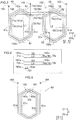
- FIG. 6 to FIG. 8 a front-side elevation of the coil is illustrated at an upper stage, and a sectional view of the coil (sectional view that is seen in the rotational axis direction) is illustrated at a lower stage.
- the one-side coil part 161 and the other-side coil part 162 for structuring each of the third coil portions 60a to 60f formed of the double-layer lap winding coils are prepared.
- Each of the third coil portions 60a to 60f (the same applies to the first coil portion 40 and the second coil portion 50 described later) is covered with insulating paper 80.
- the one-side coil part 161 and the other-side coil part 162 are caused to overlap each other so that the one-side coil part 161 is arranged on one side (arrow A1 direction side) and the other-side coil part 162 is arranged on the other side (arrow A2 direction side).
- the one-side coil part 161 and the other-side coil part 162 are deformed in a twisted manner so that the third slot-housed portion 61 of the one-side coil part 161 and the third slot-housed portion 61 of the other-side coil part 162 overlap each other in the circumferential direction.
- each of the third coil portions 60a to 60f in a state in which the one-side coil part 161 and the other-side coil part 162 are caused to overlap each other is deformed into an arc shape as seen in the rotational axis direction of the rotating electrical machine 100 so that each of the third coil portions 60a to 60f can be arranged in the slots 23.
- the third coil portion group 60 is structured by the third coil portions 60a to 60f.
- the first coil portion 40 and the second coil portion 50 continuously connected to the other-side ends 72a and 72b of the first connecting wire portion 70 having the one-side ends 71a and 71b continuously connected to the first coil portion 40 are prepared.
- the first inner coil part 141 and the first outer coil part 142 for structuring the first coil portion 40 formed of the single-layer lap winding coil are prepared.
- the second inner coil part 151 and the second outer coil part 152 for structuring the second coil portion 50 formed of the single-layer lap winding coil are prepared.
- the second inner coil part 151 is continuously connected to the other-side end 72b of the inter-coil conductor wire 70b having the one-side end 71b continuously connected to the first inner coil part 141.
- the second outer coil part 152 is continuously connected to the other-side end 72a of the inter-coil conductor wire 70a having the one-side end 71a continuously connected to the first outer coil part 142.
- the first coil portion 40 is deformed into an arc shape as seen in the rotational axis direction of the rotating electrical machine 100 so that the first coil portion 40 can be arranged in the slots 23.
- the second coil portion 50 is formed (deformed) into an arc shape.
- the first coil portion 40 formed of the single-layer lap winding coil including the pair of first slot-housed portions 41 to be arranged on the radially outer sides of the slots 23 with slot numbers #1, #2, #43, and #44 of the stator core 21 is retreated to the outside of the stator core 21.
- the second inner coil part 151 of the second coil portion 50 is moved in an arrow B1 direction, and therefore the second slot-housed portions 51 of the second inner coil part 151 are arranged on (attached to) the radially inner sides (deep sides) of the slots 23 with slot numbers #1 and #6 from opening sides of the slots 23.
- the first outer coil part 142 of the first coil portion 40 that is connected to the second inner coil part 151 by the inter-coil conductor wire 70b is moved in an arrow B2 direction, and therefore the first outer coil part 142 is retreated to (arranged on) the radially inner side of the stator core 21 (radially inner core 21b).
- the first outer coil part 142 is preferably held on the radially inner side of the stator core 21 by a manufacturing apparatus or the like.
- the first coil portion 40 when the second coil portion 50 is arranged in the stator core 21, the first coil portion 40 is retreated to a position where the first coil portion 40 and the stator core 21 do not overlap each other as seen in the rotational axis direction (as seen from an arrow Z1 direction side), and to a position on the radially inner side of the stator core 21.
- the second outer coil part 152 of the second coil portion 50 is moved in the arrow B1 direction, and therefore the second slot-housed portions 51 of the second outer coil part 152 are arranged on (attached to) the radially inner sides (deep sides) of the slots 23 with slot numbers #48 and #7 from opening sides of the slots 23.
- the first inner coil part 141 of the first coil portion 40 that is connected to the second outer coil part 152 by the inter-coil conductor wire 70a is moved in the arrow B2 direction, and therefore the first inner coil part 141 is retreated to (arranged on) the radially inner side of the stator core 21 (radially inner core 21b) so as not to interfere with the other coil portions.
- the third coil portions 30e, 30d, 30c, and 30b are arranged in this order one by one in the slots 23 of the stator core 21 from the radially outer side toward the radially inner side of the stator core 21.
- the third coil portion 60a formed of the double-layer lap winding coil including the third slot-housed portion 61 to be arranged on the radially outer sides (opening sides) of the slots 23 with slot numbers #37 and #38, and the third slot-housed portion 61 to be arranged on the radially inner sides (deep sides) of the slots 23 with slot numbers #42 and #43 (second slots) and to serve as the one-side end of the third coil portion group 60 in the circumferential direction is attached to the stator core 21 by being moved from the radially outer side to the radially inner side of the stator core 21.
- the first coil portion 40 retreated to the outside of the stator core 21 (radially inner side of the radially inner core 21b) is arranged in the stator core 21.
- the retreated first coil portion 40 is arranged by being moved from the radially inner side to the radially outer side of the stator core 21 (in an arrow B3 direction) and moved into the stator core 21 from the radially outer side of the stator core 21 (in an arrow B4 direction).
- the first outer coil part 142 of the retreated first coil portion 40 is moved from the position on the radially inner side of the stator core 21 to a position on the radially outer side of the stator core 21 by being flipped over the radially inner core 21b in the arrow B3 direction.
- the first coil portion 40 is pivoted in the axial direction across the space on the radially inner side of the stator core 21 in a state in which the first inner connecting point 141a and the first outer connecting point 142c of the first coil portion 40 are located closer to the second coil portion 50.
- the length L1 of the first outer coil part 142 is smaller than the bore diameter D1 of the stator core 21, and therefore the first outer coil part 142 and the stator core 21 can be prevented from interfering with each other when the first outer coil part 142 is flipped.
- the first outer coil part 142 moved to the radially outer side of the stator core 21 is moved in the arrow B4 direction, and therefore the first slot-housed portions 41 of the first outer coil part 142 are arranged on the radially outer sides (opening sides) of the slots 23 with slot numbers #43 and #2.
- the radially outer sides of the slots 23 with slot numbers #43 and #2 are unoccupied (see FIG. 12 ). Therefore, the first coil portion 40 is arranged in the slots 23 of the stator core 21 without temporarily removing (bypassing) the second slot-housed portion 51 of the second coil portion 50 or the third slot-housed portion 61 of the third coil portion 60a or 60f out of the slots 23.
- the first inner coil part 141 of the retreated first coil portion 40 is moved from the position on the radially inner side of the stator core 21 to a position on the radially outer side of the stator core 21 by being flipped over the radially inner core 21b in the arrow B3 direction. Subsequently, the first inner coil part 141 moved to the radially outer side of the stator core 21 is moved in the arrow B4 direction, and therefore the first slot-housed portions 41 of the first inner coil part 141 are arranged on the radially outer sides (opening sides) of the slots 23 with slot numbers #44 and #1.
- the first coil portion 40, the second coil portion 50, and the third coil portions 60a to 60f are arranged in the stator core 21 one by one.
- first coil portion 40, the second coil portion 50, and the third coil portions 60a to 60f are routed together in parallel (eight-parallel connection) by connecting wires (not illustrated) after the first coil portion 40, the second coil portion 50, and the third coil portions 60a to 60f are arranged in the slots 23.
- the first coil portion 40 formed of the single-layer lap winding coil including the pair of first slot-housed portions 41 to be arranged on the radially outer sides of the slots 23 with slot numbers #1, #2, #43, and #44 of the stator core 21 is retreated to the outside of the stator core 21.
- the second coil portion 50 continuously connected to the other-side ends 72a and 72b of the first connecting wire portion 70 having the one-side ends 71a and 71b continuously connected to the first coil portion 40, and formed of the single-layer lap winding coil including the pair of second slot-housed portions 51 to be arranged on the radially inner sides of slot numbers #6 and #7 that are different from the slots 23 with slot numbers #43 and #44 is arranged in the stator core 21.
- the third coil portion 60a formed of the double-layer lap winding coil including the third slot-housed portion 61 to be arranged on the radially inner sides (deep sides) of the slots 23 with slot numbers #42 and #43 is attached to the stator core 21.
- the first coil portion 40 retreated to the outside of the stator core 21 (radially inner side of the radially inner core 21b) is arranged in the stator core 21.
- the operation of arranging the coil 30 in the slots 23 can be mechanized (automated) easily while the increase in the size of the coil 30 (rotating electrical machine 100) is prevented.
- the arrangement of the second coil portion 50 in the stator core 21 is performed in such a manner that the second coil portion 50 is arranged in the stator core 21 in the state in which the first coil portion 40 is retreated to the position where the first coil portion 40 and the stator core 21 do not overlap each other as seen in the rotational axis direction, and to the radially inner side of the stator core 21. Therefore, when the second coil portion 50 is arranged in the stator core 21, the second coil portion 50 or the manufacturing apparatus for arranging the second coil portion 50 in the stator core 21 can be prevented from interfering with the retreated first coil portion 40. Thus, the second coil portion 50 can be arranged in the stator core 21 easily in the state in which the first coil portion 40 is retreated.
- the arrangement of the second coil portion 50 in the stator core 21 is performed in such a manner that the second coil portion 50 is arranged on the radially inner sides of slot numbers #1, #6, #7, and #48 of the stator core 21 in the state in which the first coil portion 40 is retreated to the radially inner side of the stator core 21. Therefore, when the second coil portion 50 is arranged from the radially outer side to the radially inner side of the stator core 21, the second coil portion 50 or the manufacturing apparatus for arranging the second coil portion 50 in the stator core 21 can be prevented from interfering with the retreated first coil portion 40 because the first coil portion 40 is retreated to the radially inner side of the stator core 21. As a result, the second coil portion 50 can be arranged in the stator core 21 more easily in the state in which the first coil portion 40 is retreated.
- the arrangement of the first coil portion 40 in the stator core 21 is performed in such a manner that the second coil portion 50 is arranged in the stator core 21 in the state in which the first coil portion 40 is retreated to the radially inner side of the stator core 21 and then the first coil portion 40 is moved from the radially inner side to the radially outer side of the stator core 21 (moved in the arrow B3 direction in FIG. 13 and FIG. 14 ) and is arranged in the stator core 21 from the radially outer side of the stator core 21 (moved in the arrow B4 direction in FIG. 13 and FIG. 14 ).
- the retreated first coil portion 40 can be arranged in the slots 23 easily from the radially outer side of the stator core 21.
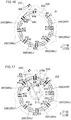
- a stator core 221 is structured to have an opening on the radially inner side unlike the first embodiment described above in which the stator core 21 is structured to have an opening on the radially outer side.
- the same components as those of the first embodiment described above are represented by the same reference symbols to omit their description.
- a coil 230 includes a first coil portion 240, a second coil portion 250, and a third coil portion group 260 (third coil portions 260a to 260f).
- the first coil portion 240 includes a first inner coil part 241 wound on an inner side in the circumferential direction, and a first outer coil part 242 wound on an outer side of the first inner coil part 241 in the circumferential direction.
- the second coil portion 250 includes a second inner coil part 251 wound on an inner side in the circumferential direction, and a second outer coil part 252 wound on an outer side of the second inner coil part 251 in the circumferential direction.
- the first inner coil part 241 and the second outer coil part 252 are continuously connected together by an inter-coil conductor wire 270a (first connecting wire portion 270).
- the first outer coil part 242 and the second inner coil part 251 are continuously connected together by an inter-coil conductor wire 270b (first connecting wire portion 270).
- the inter-coil conductor wire 270a is an example of the "one-side first connecting wire portion” and the "first connecting wire portion” in the claims.
- the inter-coil conductor wire 270b is an example of the "other-side first connecting wire portion" and the "first connecting wire portion” in the claims.
- the stator core 221 includes a plurality of (for example, 48) teeth 222 extending toward the radially inner side (center C side), and a plurality of (for example, 48) slots 223 each formed between adjacent teeth 222 and open to the radially inner side (center C side).
- a bore diameter D11 of the stator core 221 is larger than a length L11 of the second coil portion 250 (see FIG. 17 ).
- the second coil portion 250 is arranged on the radially inner sides (opening sides) of both the slots 223 with slot numbers #1 and #48 in which the first coil portion 240 is arranged.
- the third coil portion 260a is arranged on the radially inner sides (opening sides) of both the slots 223 with slot numbers #42 and #43 in which the first coil portion 240 is arranged.
- the third coil portion 260f is arranged on the radially outer sides (deep sides) of both the slots 223 with slot numbers #6 and #7 in which the second coil portion 250 is arranged.
- Each of the slots 23 with slot numbers #1 and #48 is an example of the "first slot” in the claims.
- Each of the slots 23 with slot numbers #42 and #43 is an example of the "second slot” in the claims.
- Each of the slots 23 with slot numbers #6 and #7 is an example of the "third slot” in the claims.
- a U-phase coil 230 is arranged on both of the radially inner side and the radially outer side of the slot 223 with slot number #48, and is also arranged on both of the radially inner side and the radially outer side of the slot 223 with slot number #1.
- a W-phase coil 230 is arranged on both of the radially inner side and the radially outer side of the slot 223 with slot number #2, and is also arranged on both of the radially inner side and the radially outer side of the slot 223 with slot number #3.
- a V-phase coil 230 is arranged on both of the radially inner side and the radially outer side of the slot 223 with slot number #4, and is also arranged on both of the radially inner side and the radially outer side of the slot 223 with slot number #5.
- the coils 230 are wound in the slots 223 with slot numbers #1, #2, #3, #4, #5, #6, #7, ... in the order of U-U (coil wound on radially inner side - coil wound on radially outer side), U-U, W-W, W-W, V-V, V-V, and U-U.
- the slots 223 are open to the radially inner side of the stator core 221 with the structure described above. Therefore, it is possible to first arrange the first coil portion 240 formed of the single-layer lap winding coil in the stator core 221 in a state in which the second coil portion 250 is retreated to the outside of the stator core 221 (for example, the radially outer side of the stator core 221), arrange the third coil portion group 260 formed of the double-layer lap winding coils in the stator core 221, and finally arrange, in the stator core 221, the second coil portion 250 that is arranged on the outside of the stator core 221.
- an operation of arranging the coil 30 in the slots 23 can be mechanized (automated) easily and deterioration of the balance of flux linkage can be prevented while an increase in the size of the coil 230 (rotating electrical machine 100) is prevented.
- the second coil portion 250 is structured to be arranged on the radially inner sides (opening sides) of both the slots 223 with slot numbers #1 and #48 in which the first coil portion 240 is arranged.
- the efficiency of conversion from electric power to torque can be increased as compared to the case of the first embodiment in which the second coil portion 50 is arranged on the opening side of one slot 23 with slot number #1 out of slot numbers #1 and #2 in which the first coil portion 40 is arranged.
- generation of noise and vibration at the time of driving can be prevented as compared to the structure of the second embodiment.
- a method for preparing the first coil portion 240, the second coil portion 250, and the third coil portion group 260 is similar to that of the first embodiment described above (see FIG. 3 and FIG. 5 to FIG. 9 ).
- the first coil portion 240 is arranged on the radially outer sides of the slots 223 of the stator core 221 by being moved from the radially inner side to the radially outer side of the stator core 221.
- the third coil portions 260a to 260f are arranged in this order in the slots 223 of the stator core 221.
- the retreated second coil portion 250 is moved by being flipped from the radially outer side to the radially inner side of the stator core 221 (in an arrow B11 direction), and then the second coil portion 250 is arranged on the radially inner sides (opening sides) of the slots 223 of the stator core 221 by being moved from the radially inner side to the radially outer side of the stator core 221 (in an arrow B12 direction).
- the first coil portion 240 is arranged on the radially outer sides of the slots 223 of the stator core 221 in the state in which the second coil portion 250 is retreated to the outside of the stator core 221 (radially outer side of the stator core 221). After that, the third coil portions 260a to 260f are arranged in this order in the slots 223 of the stator core 221. Thereafter, the retreated second coil portion 250 is arranged in the stator core 221.
- the operation of arranging the coil 230 in the slots 223 can be mechanized (automated) easily and the deterioration of the balance of flux linkage can be prevented while the increase in the size of the coil 230 (rotating electrical machine 200) is prevented.
- first coil portion and one second coil portion each formed of the single-layer lap winding coil are provided.
- present invention is not limited to this example.
- a plurality of first coil portions and a plurality of second coil portions may be provided.
- each of the first coil portion and the second coil portion includes the inner coil part and the outer coil part and the third coil portion includes the double-layer coil parts arranged on one side and the other side in the circumferential direction (that is, each of the first coil portion, the second coil portion, and the third coil portion is formed of a twin coil having two coil parts in sequence).
- each of the first coil portion, the second coil portion, and the third coil portion may be structured by a coil having one coil part or three or more coil parts in sequence.
- the second coil portion 50 is structured to be arranged on the radially inner side (deep side) of one slot 23 with slot number #1 out of slot numbers #1 and #2 in which the first coil portion 40 is arranged
- the third coil portion 60f is structured to be arranged on the radially outer side (opening side) of one slot 23 with slot number #7 out of slot numbers #6 and #7 in which the second coil portion 50 is arranged.
- the present invention is not limited to this example.
- the present invention is not limited to this example.
- a second coil portion 350 may be structured to be arranged on the radially inner sides of both the slots 23 with slot numbers #1 and #48 in which a first coil portion 340 is arranged, and a third coil portion 360f may be structured to be arranged on the radially outer sides of both the slots 23 with slot numbers #6 and #7 in which the second coil portion 350 is arranged.
- a rotating electrical machine 300 includes the stator core 21 formed of the radially outer core 21a and the radially inner core 21b.
- the stator core 21 is structured similarly to the stator core 21 of the first embodiment.
- the rotating electrical machine 300 includes a coil 330 formed of the first coil portion 340, the second coil portion 350, and a third coil portion group 360 (360a to 360f).
- the first coil portion 340 and the second coil portion 350 are connected together by a first connecting wire portion 370 formed of inter-coil conductor wires 370a and 370b.
- the second coil portion 350 is arranged on the radially inner sides (deep sides) of both the slots 23 with slot numbers #1 and #48 in which the first coil portion 340 is arranged.
- the third coil portion 360a is arranged on the radially inner sides (deep sides) of both the slots 23 with slot numbers #42 and #43 in which the first coil portion 340 is arranged.
- the third coil portion 360f is arranged on the radially outer sides (opening sides) of both the slots 23 with slot numbers #6 and #7 in which the second coil portion 350 is arranged.
- a U-phase coil 330 is arranged on both of the radially inner side and the radially outer side of the slot 23 with slot number #48, and is also arranged on both of the radially inner side and the radially outer side of the slot 223 with slot number #1.
- a W-phase coil 330 is arranged on both of the radially inner side and the radially outer side of the slot 23 with slot number #2, and is also arranged on both of the radially inner side and the radially outer side of the slot 23 with slot number #3.
- a V-phase coil 330 is arranged on both of the radially inner side and the radially outer side of the slot 23 with slot number #4, and is also arranged on both of the radially inner side and the radially outer side of the slot 23 with slot number #5.
- the coils 330 are wound in the slots 23 with slot numbers #1, #2, #3, #4, #5, #6, #7, ... in the order of U-U (coil wound on radially inner side - coil wound on radially outer side), U-U, W-W, W-W, V-V, V-V, and U-U.
- the efficiency of conversion from electric power to torque can be increased as compared to the first embodiment.
- generation of noise and vibration at the time of driving can be prevented as compared to the structure of the modified example.
- the second coil portion 350 of the rotating electrical machine 300 that is continuously connected to the first connecting wire portion 370 continuously connected to the first coil portion 340 is first arranged in the stator core 21 from the radially outer side toward the radially inner side in a state in which the first coil portion 340 is retreated to the outside of the stator core 21, namely, the radially inner side of the stator core 21.
- the third coil portions 360f, 360e, 360d, 360c, 360b, and 360a are attached to the stator core 21 in this order.
- the first coil portion 340 retreated to the outside of the stator core 21 (radially inner side of the radially inner core 21b) is arranged in the stator core 21 after being moved in an arrow B20 direction.
- first coil portion, the second coil portion, and the third coil portions are structured to be routed together after the first coil portion, the second coil portion, and the third coil portions are arranged in the slots.
- the present invention is not limited to this example.
- the first coil portion, the second coil portion, and the third coil portions may be arranged in the slots in a state in which the end wires of the first coil portion, the end wires of the second coil portion, and the end wires of the third coil portions are routed together.
- first coil portion, the second coil portion, and the third coil portions are arranged in the stator core one by one.
- present invention is not limited to this example.
- first coil portion, the second coil portion, and the third coil portions may be arranged in the stator core simultaneously.
- stator core is provided with 48 slots.
- present invention is not limited to this example.
- stator core may be provided with any number of slots other than 48.
- the first connecting wire portion is structured to include the inter-coil conductor wire connecting the first inner coil part and the second outer coil part together, and the inter-coil conductor wire continuously connecting the first outer coil part and the second inner coil part together.
- the first connecting wire portion may be structured to include an inter-coil conductor wire connecting the first inner coil part and the second inner coil part together, and an inter-coil conductor wire continuously connecting the first outer coil part and the second outer coil part together.
- the retreated first coil portion or the retreated second coil portion is structured to be flipped when being moved to the radially outer side or the radially inner side of the stator core.
- the present invention is not limited to this example.
- the retreated first coil portion or the retreated second coil portion may be translated in the axial direction temporarily (moved to the outer side of the stator core in the axial direction) and then moved to the radially outer side or the radially inner side of the stator core.
- the present invention is not limited to this example. That is, the length of at least one of the first coil portion and the second coil portion in the rotational axis direction may be set smaller than the bore diameter of the stator core.
Landscapes
- Engineering & Computer Science (AREA)
- Power Engineering (AREA)
- Manufacturing & Machinery (AREA)
- Windings For Motors And Generators (AREA)
- Manufacture Of Motors, Generators (AREA)
Abstract
Description
- The present invention relates to a stator coil, a method for manufacturing a stator, and a rotating electrical machine.
- Hitherto, there is known a rotating electrical machine including double-layer lap winding coils, in each of which one of a pair of slot-housed portions of the coil that are arranged in slots is arranged on a radially outer side of the slot and the other of the pair of slot-housed portions is arranged on a radially inner side of the slot. Such a rotating electrical machine is disclosed in, for example, Japanese Patent Application Publication No.
2009-195004 JP 2009-195004 A - In the rotating electrical machine described in Japanese Patent Application Publication No.
2009-195004 JP 2009-195004 A 2009-195004 JP 2009-195004 A - In the rotating electrical machine described in Japanese Patent Application Publication No.
2009-195004 JP 2009-195004 A - In the case of the structure described above, however, when the one single-layer lap winding coil arranged only on the deep sides (one of the radially outer sides and the radially inner sides) of the slots and that other single-layer lap winding coil arranged only on the shallow sides (the other of the radially outer sides and the radially inner sides) of the slots are individually connected to a power line in parallel to each other, it is conceivable that the balance of flux linkage may be poorer than that of the double-layer lap winding coil due to a difference in the radial arrangement positions of the one single-layer lap winding coil and the other single-layer lap winding coil. In this case, it is conceivable that the one single-layer lap winding coil and the other single-layer lap winding coil are routed together (routing is changed) after the one single-layer lap winding coil and that other single-layer lap winding coil are arranged in the stator core in order to prevent the deterioration of the balance of flux linkage. Thus, it is conceivable that the one single-layer lap winding coil and that other single-layer lap winding coil are structured to be connected together so as to have a balance of flux linkage similar to that of the double-layer lap winding coil.
- Patent Document 1: Japanese Patent Application Publication No.
2009-195004 JP 2009-195004 A - However, it is necessary to manually perform the operation of routing (or changing the routing of) the one single-layer lap winding coil and that other single-layer lap winding coil after the one single-layer lap winding coil and that other single-layer lap winding coil are arranged in the stator core. Therefore, mechanization (automation) is difficult. Further, it is necessary to secure a space for providing a connecting terminal and an insulating member in order to perform the routing (or change the routing). Therefore, there is an inconvenience of an increase in the size of the stator coil (rotating electrical machine). Thus, the stator coil having the structure described above has a problem in terms of difficulty in achieving mechanization (automation) of the operation of arranging the stator coil in the slots while the increase in the size of the stator coil (rotating electrical machine) is prevented.
- The present invention has been made to solve the problem described above, and it is one object of the present invention to provide a stator coil, a method for manufacturing a stator, and a rotating electrical machine, in which an operation of arranging the stator coil in slots can be mechanized (automated) easily preventing an increase in the size of the stator coil (rotating electrical machine).
- In order to achieve the object described above, a stator coil according to a first aspect of the present invention is a coil to be arranged in a stator core. The coil includes a first coil portion formed of a single-layer lap winding coil including a pair of first slot-housed portions to be respectively arranged on a radially outer side of a first slot and on a radially outer side of a second slot, a second coil portion continuously connected to an other-side end of a first connecting wire portion having a one-side end continuously connected to the first coil portion, and formed of a single-layer lap winding coil including a pair of second slot-housed portions, one of which is arranged on a radially inner side of the first slot and the other of which is arranged on a radially inner side of a third slot different from the first slot and the second slot, and a third coil portion group including a plurality of third coil portions each formed of a double-layer lap winding coil. A third slot-housed portion at a one-side end of the third coil portion group in a circumferential direction is arranged on a radially inner side of the second slot, and a third slot-housed portion at an other-side end of the third coil portion group in the circumferential direction is arranged on a radially outer side of the third slot.
- In the stator coil according to the first aspect of the present invention, with the structure described above, for example, when the slots are open to a radially outer side of the stator core, it is possible to first arrange the second coil portion formed of the single-layer lap winding coil in the stator core in a state in which the first coil portion is retreated to the outside of the stator core (for example, a radially inner side of the stator core), arrange the third coil portion group including the plurality of third coil portions each formed of the double-layer lap winding coil in the stator core, and finally arrange, in the stator core, the first coil portion that is arranged on (retreated to) the outside of the stator core. Therefore, there is no need to temporarily remove, from the slots, a slot-housed portion of a double-layer lap winding coil that is first arranged. There is no need to route (or change the routing of) the first coil portion and the second coil portion after the first coil portion and the second coil portion are arranged in the stator core. Thus, the operation of arranging the stator coil in the slots can be mechanized (automated) easily. Further, there is no need to route (or change the routing of) the first coil portion and the second coil portion after the first coil portion and the second coil portion are arranged in the stator core. Therefore, there is no need to secure a space for providing a connecting terminal and an insulating member for performing the routing (or changing the routing). Thus, the increase in the size of the stator coil (rotating electrical machine) can be prevented. As a result, the operation of arranging the stator coil in the slots can be mechanized (automated) easily while preventing the increase in the size of the stator coil (rotating electrical machine).
- A method for manufacturing a stator according to a second aspect of the present invention is a method for manufacturing a stator including a stator core having a first slot, a second slot, and a third slot that are different slots. The method includes arranging, in a state in which one of a first coil portion and a second coil portion is retreated to an outside of the stator core, the other of the first coil portion and the second coil portion in the stator core, the first coil portion being formed of a single-layer lap winding coil including a pair of first slot-housed portions to be respectively arranged on a radially outer side of the first slot and on a radially outer side of the second slot of the stator core, the second coil portion being continuously connected to an other-side end of a first connecting wire portion having a one-side end continuously connected to the first coil portion, and formed of a single-layer lap winding coil including a pair of second slot-housed portions, one of which is arranged on a radially inner side of the first slot and the other of which is arranged on a radially inner side of the third slot different from the first slot and the second slot, subsequently arranging, on a radially inner side of the second slot, a third slot-housed portion at a one-side end of a third coil portion group in a circumferential direction, the third coil portion group including a plurality of third coil portions each formed of a double-layer lap winding coil, and arranging, on a radially outer side of the third slot, a third slot-housed portion at an other-side end of the third coil portion group in the circumferential direction, and subsequently arranging, in the stator core, the one of the first coil portion and the second coil portion that is retreated to the outside of the stator core.
- In the method for manufacturing a stator according to the second aspect of the present invention, with the structure described above, it is possible to provide a method for manufacturing a stator in which the operation of arranging the stator coil in the slots can be mechanized (automated) easily while the increase in the size of the stator coil (rotating electrical machine) is prevented.
- A rotating electrical machine according to a third aspect of the present invention includes a rotor core provided with a permanent magnet, a stator core arranged so as to face the rotor core in a radial direction, and having a first slot, a second slot, and a third slot that are different slots, and a coil arranged in the stator core. The coil includes a first coil portion formed of a single-layer lap winding coil including a pair of first slot-housed portions respectively arranged on a radially outer side of the first slot and on a radially outer side of the second slot, a second coil portion continuously connected to an other-side end of a first connecting wire portion having a one-side end continuously connected to the first coil portion, and formed of a single-layer lap winding coil including a pair of second slot-housed portions, one of which is arranged on a radially inner side of the first slot and the other of which is arranged on a radially inner side of the third slot different from the first slot and the second slot, and a third coil portion group including a plurality of third coil portions each formed of a double-layer lap winding coil. A third slot-housed portion at a one-side end of the third coil portion group in a circumferential direction is arranged on a radially inner side of the second slot, and a third slot-housed portion at an other-side end of the third coil portion group in the circumferential direction is arranged on a radially outer side of the third slot.
- In the rotating electrical machine according to the third aspect of the present invention, with the structure described above, it is possible to provide, also in the rotating electrical machine according to the third aspect, a rotating electrical machine in which the operation of arranging the stator coil in the slots can be mechanized (automated) easily while the increase in the size of the stator coil (rotating electrical machine) is prevented.
- According to the present invention, as described above, the operation of arranging the stator coil in the slots can be mechanized (automated) easily while the increase in the size of the stator coil (rotating electrical machine) is prevented.
-
- [
FIG. 1] FIG. 1 is a plan view of a rotating electrical machine according to a first embodiment of the present invention. - [
FIG. 2] FIG. 2 is a view illustrating a coil of the rotating electrical machine according to the first embodiment of the present invention. - [
FIG. 3] FIG. 3 is a view illustrating a first coil portion and a second coil portion of the rotating electrical machine according to the first embodiment of the present invention. - [
FIG. 4] FIG. 4 is a diagram for describing the lengths of a first connecting wire portion of the rotating electrical machine according to the first embodiment of the present invention. - [
FIG. 5] FIG. 5 is a view illustrating a third coil portion of the rotating electrical machine according to the first embodiment of the present invention. - [
FIG. 6] FIG. 6 is a view (1) for describing a method for manufacturing the third coil portion of the rotating electrical machine according to the first embodiment of the present invention. - [
FIG. 7] FIG. 7 is a view (2) for describing the method for manufacturing the third coil portion of the rotating electrical machine according to the first embodiment of the present invention. - [
FIG. 8] FIG. 8 is a view (3) for describing the method for manufacturing the third coil portion of the rotating electrical machine according to the first embodiment of the present invention. - [
FIG. 9] FIG. 9 is a view for describing a method for manufacturing the first coil portion and the second coil portion of the rotating electrical machine according to the first embodiment of the present invention. - [
FIG. 10] FIG. 10 is a view (1) for describing retreat of the first coil portion and arrangement of the second coil portion in a stator core in the rotating electrical machine according to the first embodiment of the present invention. - [
FIG. 11] FIG. 11 is a view (2) for describing the retreat of the first coil portion and the arrangement of the second coil portion in the stator core in the rotating electrical machine according to the first embodiment of the present invention. - [
FIG. 12] FIG. 12 is a view for describing arrangement of the third coil portion in the stator core in the rotating electrical machine according to the first embodiment of the present invention. - [
FIG. 13] FIG. 13 is a view (1) for describing arrangement of the retreated first coil portion in the stator core in the rotating electrical machine according to the first embodiment of the present invention. - [
FIG. 14] FIG. 14 is a view (2) for describing the arrangement of the retreated first coil portion in the stator core in the rotating electrical machine according to the first embodiment of the present invention. - [
FIG. 15] FIG. 15 is a plan view of a rotating electrical machine according to a second embodiment of the present invention. - [
FIG. 16] FIG. 16 is a view for describing retreat of a second coil portion and arrangement of a first coil portion and a third coil portion in a stator core in the rotating electrical machine according to the second embodiment of the present invention. - [
FIG. 17] FIG. 17 is a view for describing arrangement of the retreated second coil portion in the stator core in the rotating electrical machine according to the second embodiment of the present invention. - [
FIG. 18] FIG. 18 is a view illustrating an inner peripheral core of a rotating electrical machine according to a modified example of the first embodiment of the present invention. - [
FIG. 19] FIG. 19 is a view for describing the arrangement of the retreated first coil portion in the stator core in the rotating electrical machine according to the modified example of the first embodiment of the present invention. - Embodiments of the present invention are described below with reference to the drawings.
- The structure of a rotating
electrical machine 100 according to a first embodiment is described with reference toFIG. 1 to FIG. 5 . For example, the rotatingelectrical machine 100 illustrated inFIG. 1 is a motor (preferably a three-phase brushless motor).FIG. 2 illustrates only acoil 30 of one phase out ofcoils 30 of three phases. Thecoil 30 is an example of a "stator coil" in the claims. - A simple phase "rotational axis direction" or "axial direction" herein refers to a rotational axis direction of the rotating
electrical machine 100, which means a direction parallel to a Z-axis in the drawings. A simple phase "circumferential direction" refers to a circumferential direction of the rotatingelectrical machine 100, which means an arrow A1 direction or an arrow A2 direction in the drawings. A simple phase "radial direction" refers to a radial direction of the rotatingelectrical machine 100, which means an arrow R1 direction or an arrow R2 direction in the drawings. A simple phase "radially inner side" refers to a radially inner side of the rotatingelectrical machine 100, which means the arrow R1 direction side in the drawings. A simple phase "radially outer side" refers to a radially outer side of the rotatingelectrical machine 100, which means the arrow R2 direction side in the drawings. - As illustrated in
FIG. 1 , the rotatingelectrical machine 100 includes arotor 10. Arotor core 11 of therotor 10 is provided with a plurality ofpermanent magnets 12. Thepermanent magnets 12 are arranged substantially equiangularly along the circumferential direction. - The rotating
electrical machine 100 includes a stator 20 (stator core 21) arranged so as to face the outer peripheral surface of therotor core 11 in the radial direction. Thestator core 21 is formed as an internal-external divisible stator core (internal-external divisible iron core). - Specifically, the
stator core 21 includes a radiallyouter core 21a (outer peripheral iron core) arranged on a radially outer side of thestator core 21, and a radiallyinner core 21b (inner peripheral iron core) arranged on a radially outer side of thestator core 21. The radiallyinner core 21b is provided with a plurality of (for example, 48)teeth 22. The radiallyinner core 21b includes theteeth 22 and a plurality of (for example, 48)slots 23 each located betweenadjacent teeth 22. In the first embodiment, theslots 23 are open to a radially outer side of the radiallyinner core 21b. Thestator core 21 having the plurality of (in the first embodiment, 48) slots 23 (closed slots) is structured by combining the radiallyouter core 21a and the radiallyinner core 21b together. - The
coil 30 is arranged in theslots 23 of thestator core 21. For example, thecoil 30 is structured by conductor wires. The conductor wire may be formed as any one of a rectangular wire and a round wire. - As illustrated in
FIG. 1 , thestator core 21 is structured to have a bore diameter D1 (bore diameter of the radiallyinner core 21b). The bore diameter D1 is larger than a length L1 of afirst coil portion 40 in the axial direction (seeFIG. 3 ), and is larger than a length L2 of asecond coil portion 50 in the axial direction (seeFIG. 3 ). - Next, the structure of the
coil 30 is described with reference toFIG. 2. FIG. 2 illustrates only thecoil 30 of one phase that is arranged in the 48 (slot numbers # 1 to #48)slots 23. - For example, in the first embodiment, a
U-phase coil 30 is arranged on both of a radially inner side and a radially outer side of theslot 23 withslot number # 1, a W-phase coil 30 is arranged on a radially inner side of theslot 23 withslot number # 2, and theU-phase coil 30 is arranged on a radially outer side of theslot 23 withslot number # 2. The W-phase coil 30 is arranged on both of a radially inner side and a radially outer side of theslot 23 with slot number #3. Thus, thecoils 30 are wound in theslots 23 withslot numbers # 1, #2, #3, #4, #5, #6, #7, ... in the order of U-U (coil wound on radially inner side - coil wound on radially outer side), U-W, W-W, W-V, V-V, V-U, and U-U. - In the first embodiment, the
coil 30 includes thefirst coil portion 40, thesecond coil portion 50, and a third coil portion group 60 (third coil portions 60a to 60f). Each of thecoils 30 of the three phases (U phase, V phase, and W phase) includes thefirst coil portion 40, thesecond coil portion 50, and the thirdcoil portion group 60. - As illustrated in
FIG. 2 , thefirst coil portion 40 is formed of a single-layer lap winding coil including a plurality of (for example, two) concentric coil parts that are a firstinner coil part 141 and a firstouter coil part 142. Specifically, in the first embodiment, thefirst coil portion 40 is formed of a single-layer lap winding coil including a pair of first slot-housedportions 41 respectively arranged on the radially outer sides (opening sides) of theslots 23 withslot numbers # 1 and #2 and on radially outer sides (opening sides) of theslots 23 with slot numbers #43 and #44, and firstcoil end portions 42 connecting the pair of first slot-housedportions 41 together on both sides in the rotational axis direction. The single-layer lap winding coil herein refers to a coil having slot-housed portions respectively arranged only on radially outer sides of theslots 23 or only on radially inner sides of theslots 23. Each of theslots 23 withslot numbers # 1, #2, and #48 is an example of a "first slot". Each of theslots 23 with slot numbers #42, #43, and #44 is an example of a "second slot". - The
second coil portion 50 is formed of a single-layer lap winding coil including a plurality of (for example, two) concentric coil parts that are a secondinner coil part 151 and a secondouter coil part 152. Specifically, in the first embodiment, thesecond coil portion 50 is formed of a single-layer lap winding coil including a pair of second slot-housedportions 51 respectively arranged on radially inner sides (deep sides) of theslots 23 withslot numbers # 1 and #48 and on radially inner sides (deep sides) of theslots 23 withslot numbers # 6 and #7 that are slots different from those with slot numbers #43 and #44 and are arranged opposite to slotnumbers # 1 and #48 from slot numbers #43 and #44 in the circumferential direction (on the arrow A1 direction side), and secondcoil end portions 52 connecting the pair of second slot-housedportions 51 together on both sides in the rotational axis direction. Each of theslots 23 withslot numbers # 6, #7, and #8 is an example of a "third slot". - The third
coil portion group 60 includes thethird coil portions 60a to 60f. In the first embodiment, each of thethird coil portions 60a to 60f is formed of a double-layer lap winding coil including a plurality of (for example, two (twin)) double-layer coil parts (one-side coil part 161 and other-side coil part 162). The double-layer lap winding coil herein refers to a coil having slot-housed portions respectively arranged on radially outer sides of theslots 23 and on radially inner sides of theslots 23. Thethird coil portion 60a includes a third slot-housedportion 61 arranged on radially inner sides of theslots 23 with slot numbers #42 and #43. Thethird coil portion 60f includes a third slot-housedportion 61 arranged on radially outer sides of theslots 23 withslot numbers # 7 and #8. In thethird coil portions 60b to 60e, a third slot-housedportion 61 of one of adjacent third coil portions (any one of thethird coil portions 60b to 60e) is arranged on a radially outer side of thesame slot 23, and a third slot-housedportion 61 of the other the adjacent third coil portions (any one of thethird coil portions 60b to 60e) is arranged on a radially inner side of thesame slot 23. Each of the one-side coil part 161 and the other-side coil part 162 is an example of a "double-layer coil part" in the claims. - In the
coil 30, portions other than thefirst coil portion 40 formed of the single-layer lap winding coil and thesecond coil portion 50 formed of the single-layer lap winding coil are structured by the thirdcoil portion group 60 including thethird coil portions 60a to 60f each formed of the double-layer lap winding coil. - In the first embodiment, as illustrated in
FIG. 3 , the firstinner coil part 141 of thefirst coil portion 40 is wound on an inner side of the firstouter coil part 142 in the circumferential direction and in the axial direction (concentric circle). The firstouter coil part 142 is wound on an outer side of the firstinner coil part 141 in the circumferential direction and in the axial direction (outer side with respect to the concentric circle). The secondinner coil part 151 of thesecond coil portion 50 is wound on an inner side of the secondouter coil part 152 in the circumferential direction (concentric circle). The secondouter coil part 152 is wound on an outer side of the secondinner coil part 151 in the circumferential direction (outer side with respect to the concentric circle). Each of the firstinner coil part 141, the firstouter coil part 142, the secondinner coil part 151, and the secondouter coil part 152 is formed of a conductor wire (rectangular wire or round wire) that is wound a plurality of times. - In the first embodiment, as illustrated in
FIG. 3 , the length L1 of thefirst coil portion 40 in the rotational axis direction is smaller than the bore diameter D1 of the stator core 21 (seeFIG. 1 ). The length L2 of thesecond coil portion 50 in the rotational axis direction is smaller than the bore diameter D1 of thestator core 21. The length L1 of thefirst coil portion 40 in the rotational axis direction refers to a distance between anupper end 142a and alower end 142b of the firstouter coil part 142. The length L2 of thesecond coil portion 50 in the rotational axis direction refers to a distance between anupper end 152a and alower end 152b of the secondouter coil part 152.FIG. 3 illustrates that the length L1 of thefirst coil portion 40 in the rotational axis direction and the length L2 of thesecond coil portion 50 in the rotational axis direction are substantially equal to each other, but the length L1 and the length L2 may be different from each other. - In the first embodiment, as illustrated in
FIG. 3 , thecoil 30 includes a first connectingwire portion 70. Thesecond coil portion 50 is continuously connected to other-side ends 72a and 72b of the first connectingwire portion 70 having one-side ends 71a and 71b continuously connected to thefirst coil portion 40. That is, thefirst coil portion 40, thesecond coil portion 50, and the first connectingwire portion 70 are formed of a single continuous conductor wire. Specifically, the first connectingwire portion 70 connects the firstcoil end portion 42 and the secondcoil end portion 52 together. - Specifically, the first connecting
wire portion 70 includesinter-coil conductor wires inter-coil conductor wire 70a is structured to continuously connect the firstcoil end portion 42 of the firstinner coil part 141 and the secondcoil end portion 52 of the secondouter coil part 152 together. Theinter-coil conductor wire 70b is structured to continuously connect the firstcoil end portion 42 of the firstouter coil part 142 and the secondcoil end portion 52 of the secondinner coil part 151 together. That is, the firstinner coil part 141 and the secondouter coil part 152 are connected together in series. The firstouter coil part 142 and the secondinner coil part 151 are connected together in series. - The
inter-coil conductor wire 70a is an example of a "one-side first connecting wire portion" and a "first connecting wire portion" in the claims. Theinter-coil conductor wire 70b is an example of an "other-side first connecting wire portion" and the "first connecting wire portion" in the claims. The term "continuously" herein refers to not only a state in which components are simply connected together, but also a state in which coils are connected together without connecting conductor wires together by using, for example, a connecting terminal.FIG. 3 illustrates a singleinter-coil conductor wire 70a and a singleinter-coil conductor wire 70b (as a single conductor wire), but a plurality ofinter-coil conductor wires 70a and a plurality ofinter-coil conductor wires 70b may be structured (as a plurality of conductor wires). - The first
inner coil part 141 includes a first inner connectingpoint 141a continuously connected to the one-side end 71a of theinter-coil conductor wire 70a. The firstouter coil part 142 includes a first outer connectingpoint 142c continuously connected to the one-side end 71b of theinter-coil conductor wire 70b. The first inner connectingpoint 141a and the first outer connectingpoint 142c are provided on the firstcoil end portion 42. The secondinner coil part 151 includes a second inner connectingpoint 151a continuously connected to the other-side end 72b of theinter-coil conductor wire 70b. The secondouter coil part 152 includes a second outer connectingpoint 152c continuously connected to the other-side end 72a of theinter-coil conductor wire 70a. The second inner connectingpoint 151a and the second outer connectingpoint 152c are provided on the secondcoil end portion 52. The first inner connectingpoint 141a is an example of a "first connecting portion" in the claims. The first outer connectingpoint 142c is an example of the "first connecting portion" in the claims. The second inner connectingpoint 151a is an example of a "second connecting portion" in the claims. The second outer connectingpoint 152c is an example of the "second connecting portion" in the claims. - More specifically, as illustrated in
FIG. 2 , first slot-housedportions inner coil part 141 are respectively arranged on the radially outer sides of theslots 23 with slot numbers #44 and #1. First slot-housedportions outer coil part 142 are respectively arranged on the radially outer sides of theslots 23 with slot numbers #43 and #2. Second slot-housedportions inner coil part 151 are respectively arranged on the radially inner sides of theslots 23 withslot numbers # 1 and #6. Second slot-housedportions outer coil part 152 are respectively arranged on the radially inner sides of theslots 23 with slot numbers #48 and #7. - The
inter-coil conductor wire 70a continuously connects the first inner coil part 141 (vicinity of slot number #44) and the second outer coil part 152 (vicinity of slot number #48) together. Theinter-coil conductor wire 70b continuously connects the first outer coil part 142 (vicinity of slot number #2) and the second inner coil part 151 (vicinity of slot number #6) together. - In the first embodiment, as illustrated in
FIG. 4 , a length L3 of theinter-coil conductor wire 70a is larger than a shortest distance D2 between the first inner connectingpoint 141a and the first outer connectingpoint 142c. A length L4 of theinter-coil conductor wire 70a is larger than a shortest distance D3 between the first inner connectingpoint 141a and the first outer connectingpoint 142c. That is, the first connectingwire portion 70 has the lengths L3 and L4 that allow thesecond coil portion 50 to be attached to thestator core 21 in a state in which thefirst coil portion 40 and thesecond coil portion 50 are connected together and thefirst coil portion 40 is retreated to the outside of the stator core 21 (center C side of the radiallyinner core 21b). The first connectingwire portion 70 has the lengths L3 and L4 that allow the retreatedfirst coil portion 40 to be attached to thestator core 21 in a state in which thesecond coil portion 50 is attached to thestator core 21. - As illustrated in
FIG. 5 , each of thethird coil portions 60a to 60f includes the one-side coil part 161 arranged on one side in the circumferential direction (arrow A1 direction side), and the other-side coil part 162 arranged on the other side in the circumferential direction (arrow A2 direction side). Each of the one-side coil part 161 and the other-side coil part 162 is formed of a conductor wire (rectangular wire or round wire) that is wound a plurality of times. The one-side coil part 161 and the other-side coil part 162 are connected together in series by aninter-coil conductor wire 163. Theinter-coil conductor wire 163 is an example of a "second connecting wire portion" in the claims.FIG. 5 illustrates theinter-coil conductor wire 163 as a single conductor wire, but theinter-coil conductor wire 163 may be structured as a plurality of conductor wires. - In the first embodiment, as illustrated in
FIG. 4 , the length L3 of theinter-coil conductor wire 70a and the length L4 of theinter-coil conductor wire 70a are larger than a length L5 of theinter-coil conductor wire 163 connecting the one-side coil part 161 and the other-side coil part 162 of each of thethird coil portions 60a to 60f together. - As illustrated in
FIG. 2 , the one-side coil part 161 of thethird coil portion 60a is wound (arranged) in theslots 23 with slot numbers #38 and #43. The other-side coil part 162 of thethird coil portion 60a is wound in theslots 23 with slot numbers #37 and #42. The one-side coil part 161 of thethird coil portion 60f is wound in theslots 23 withslot numbers # 8 and #12. The other-side coil part 162 of thethird coil portion 60f is wound in theslots 23 withslot numbers # 7 and #11. - Third slot-housed
portions third coil portion 60a (third slot-housedportions coil portion group 60 in the circumferential direction) are respectively arranged on the radially inner sides of theslots 23 with slot numbers #42 and #43 (second slots). Third slot-housedportions third coil portion 60a are respectively arranged on radially outer sides of theslots 23 with slot numbers #37 and #38. - Third slot-housed
portions third coil portion 60f are respectively arranged on radially inner sides of theslots 23 with slot numbers #11 and #12. Third slot-housedportions third coil portion 60f (third slot-housedportions coil portion group 60 in the circumferential direction) are respectively arranged on the radially outer sides of theslots 23 withslot numbers # 7 and #8 (third slots). - In the first embodiment, as illustrated in
FIG. 1 and FIG. 2 , thecoil 30 including thefirst coil portion 40, thesecond coil portion 50, and the thirdcoil portion group 60 is structured to be attached to theslots 23 from the radially outer side toward the radially inner side of the stator core 21 (radiallyinner core 21b).End wires 143 of the first coil portion 40 (seeFIG. 3 ),end wires 153 of thesecond coil portion 50, and endwires 164 of the third coil portion group 60 (seeFIG. 5 ) are structured to be routed together by connecting wires (not illustrated) after thefirst coil portion 40, thesecond coil portion 50, and the thirdcoil portion group 60 are arranged in theslots 23. Thus, thefirst coil portion 40, thesecond coil portion 50, and thethird coil portions 60a to 60f of the thirdcoil portion group 60 are connected together in parallel (eight-parallel connection). - In the first embodiment, the following effects can be attained.
- In the first embodiment, as illustrated in
FIG. 2 , thecoil 30 includes thefirst coil portion 40 formed of the single-layer lap winding coil including the pair of first slot-housedportions 41 respectively arranged on the radially outer sides of theslots 23 withslot numbers # 1 and #2 and on the radially outer sides of theslots 23 with slot numbers #43 and #44. Thecoil 30 further includes thesecond coil portion 50 continuously connected to the other-side ends 72a and 72b of the first connectingwire portion 70 having the one-side ends 71a and 71b continuously connected to thefirst coil portion 40, and formed of the single-layer lap winding coil including the pair of second slot-housedportions 51 respectively arranged on the radially inner sides of theslots 23 withslot numbers # 1 and #48 and on the radially inner sides of theslots 23 withslot numbers # 6 and #7 that are theslots 23 different from theslots 23 with slot numbers #43 and #44 and are arranged opposite to theslots 23 withslot numbers # 1 and #48 from theslots 23 with slot numbers #43 and #44. Thecoil 30 further includes the thirdcoil portion group 60 including thethird coil portions 60a to 60f each formed of the double-layer lap winding coil. Thecoil 30 includes thethird coil portion 60a including the third slot-housedportion 61 arranged on the radially inner sides of theslots 23 with slot numbers #42 and #43 and serving as the one-side end of the thirdcoil portion group 60 in the circumferential direction, and thethird coil portion 60f including the third slot-housedportion 61 arranged on the radially outer sides of theslots 23 withslot numbers # 6 and #7 and serving as the other-side end of the thirdcoil portion group 60 in the circumferential direction. Thus, when theslots 23 are open to the radially outer side of thestator core 21, it is possible to first arrange thesecond coil portion 50 formed of the single-layer lap winding coil in thestator core 21 in the state in which thefirst coil portion 40 is retreated to the outside of the stator core 21 (for example, the radially inner side of the stator core 21), arrange the thirdcoil portion group 60 formed of the double-layer lap winding coils in thestator core 21, and finally arrange, in thestator core 21, thefirst coil portion 40 that is arranged on (retreated to) the outside of thestator core 21. - As a result, in the first embodiment, the first slot-housed
portions 41 of thefirst coil portion 40 can be arranged inslot numbers # 1, #2, #43, and #44 without bypassing (temporarily removing) the second slot-housedportion 51 of thesecond coil portion 50 that is first arranged in thestator core 21 while keeping the state in which thefirst coil portion 40 and thesecond coil portion 50 are continuously connected together. Thus, an operation of arranging thecoil 30 in theslots 23 can be mechanized (automated) easily. There is no need to route (or change the routing of) thefirst coil portion 40 and thesecond coil portion 50 after thefirst coil portion 40 and thesecond coil portion 50 are arranged in thestator core 21. Thus, the operation of arranging thecoil 30 in theslots 23 can be mechanized (automated) easily. - There is no need to route (or change the routing of) the
first coil portion 40 and thesecond coil portion 50. Therefore, there is no need to secure a space for providing a connecting terminal and an insulating member for performing the routing (or changing the routing). Thus, an increase in the size of the coil 30 (rotating electrical machine 100) can be prevented. As a result, the operation of arranging thecoil 30 in theslots 23 can be mechanized (automated) easily and deterioration of the balance of flux linkage can be prevented while the increase in the size of the coil 30 (rotating electrical machine 100) is prevented. - In the first embodiment, the
second coil portion 50 is structured to be continuously connected to the other-side ends 72a and 72b of the first connectingwire portion 70 having the one-side ends 71a and 71b continuously connected to thefirst coil portion 40. Therefore, thesecond coil portion 50 and thefirst coil portion 40 can be structured to have a connection relationship equivalent to the double-layer lap winding coil. Thus, even when thefirst coil portion 40 and thesecond coil portion 50 are structured by the single-layer lap winding coils, the deterioration of the balance of flux linkage can be prevented. As a result, the operation of arranging thecoil 30 in theslots 23 can be mechanized (automated) easily and the deterioration of the balance of flux linkage can be prevented while the increase in the size of the coil 30 (rotating electrical machine 100) is prevented. - In the first embodiment, each of the
third coil portions 60a to 60f is structured such that the one-side coil part 161 and the other-side coil part 162 are continuously connected together via theinter-coil conductor wire 163. Theinter-coil conductor wire 70a is structured to have the length L3 that is larger than the length L5 of theinter-coil conductor wire 163. Theinter-coil conductor wire 70b is structured to have the length L4 that is larger than the length L5 of theinter-coil conductor wire 163. Thus, thesecond coil portion 50 can be arranged in thestator core 21 easily in the state in which thefirst coil portion 40 is retreated to the outside of thestator core 21 because the lengths of the first connecting wire portion 70 (inter-coil conductor wires - In the first embodiment, the
first coil portion 40 is provided with the firstinner coil part 141 wound on the inner side in the circumferential direction, and the firstouter coil part 142 wound on the outer side of the firstinner coil part 141 in the circumferential direction. Thesecond coil portion 50 is provided with the secondinner coil part 151 wound on the inner side in the circumferential direction, and the secondouter coil part 152 wound on the outer side of the secondinner coil part 151 in the circumferential direction. The first connectingwire portion 70 is provided with theinter-coil conductor wire 70a continuously connecting the firstinner coil part 141 and the secondouter coil part 152 together, and theinter-coil conductor wire 70b continuously connecting the firstouter coil part 142 and the secondinner coil part 151 together. Thus, even when thefirst coil portion 40 and thesecond coil portion 50 are structured by the twin single-layer lap winding coils, thesecond coil portion 50 can be arranged in thestator core 21 in the state in which thefirst coil portion 40 is retreated to the outside of thestator core 21 owing to theinter-coil conductor wires first coil portion 40 and thesecond coil portion 50 can be structured to have a connection relationship equivalent to the double-layer lap winding coil owing to theinter-coil conductor wires - In the first embodiment, the length L1 of the
first coil portion 40 in the rotational axis direction is set smaller than the bore diameter D1 of thestator core 21. Thus, it is possible to arrange thesecond coil portion 50 in thestator core 21 while retreating thefirst coil portion 40 to the radially inner side of thestator core 21, and then arrange thefirst coil portion 40 in thestator core 21 by pivoting thefirst coil portion 40 in the axial direction across the space on the radially inner side of thestator core 21 in a state in which the first inner connectingpoint 141a and the first outer connectingpoint 142c of thefirst coil portion 40 are located closer to thesecond coil portion 50. As a result, the necessary length of the first connectingwire portion 70 can be reduced because the first inner connectingpoint 141a and the first outer connectingpoint 142c are located closer to thesecond coil portion 50 as compared to a case where thefirst coil portion 40 is arranged on an outer side of thestator core 21 in the axial direction and is translated in the axial direction. As a result, an increase in the size of the space necessary to arrange the first connectingwire portion 70 can be prevented. Thus, an increase in the size of the rotating electrical machine 100 (stator) can be prevented. - In the first embodiment, the first
inner coil part 141 of thefirst coil portion 40 is structured to include the first inner connectingpoint 141a continuously connected to the one-side end 71a of theinter-coil conductor wire 70a. The firstouter coil part 142 of thefirst coil portion 40 is structured to include the first outer connectingpoint 142c continuously connected to the one-side end 71b of theinter-coil conductor wire 70b. The secondinner coil part 151 of thesecond coil portion 50 is structured to include the second inner connectingpoint 151a continuously connected to the other-side end 72b of theinter-coil conductor wire 70b. The secondouter coil part 152 of thesecond coil portion 50 is structured to include the second outer connectingpoint 152c continuously connected to the other-side end 72a of theinter-coil conductor wire 70a. The length L3 of theinter-coil conductor wire 70a is set larger than the shortest distance D2 between the first inner connectingpoint 141a and the first outer connectingpoint 142c. The length L4 of theinter-coil conductor wire 70a is set larger than the shortest distance D3 between the first inner connectingpoint 141a and the first outer connectingpoint 142c. Thus, thesecond coil portion 50 can be arranged in thestator core 21 easily in the state in which thefirst coil portion 40 is retreated to the outside of thestator core 21 owing to the first connecting wire portion 70 (inter-coil conductor wires - Next, a method for manufacturing the
stator 20 of the rotating electrical machine 100 (method for manufacturing the coil 30) is described with reference toFIG. 1 ,FIG. 3 , andFIG. 6 toFIG. 14 . InFIG. 6 to FIG. 8 , a front-side elevation of the coil is illustrated at an upper stage, and a sectional view of the coil (sectional view that is seen in the rotational axis direction) is illustrated at a lower stage. - As illustrated in
FIG. 6 , the one-side coil part 161 and the other-side coil part 162 for structuring each of thethird coil portions 60a to 60f formed of the double-layer lap winding coils are prepared. Each of thethird coil portions 60a to 60f (the same applies to thefirst coil portion 40 and thesecond coil portion 50 described later) is covered with insulatingpaper 80. - Next, as illustrated in
FIG. 7 , the one-side coil part 161 and the other-side coil part 162 are caused to overlap each other so that the one-side coil part 161 is arranged on one side (arrow A1 direction side) and the other-side coil part 162 is arranged on the other side (arrow A2 direction side). At this time, the one-side coil part 161 and the other-side coil part 162 are deformed in a twisted manner so that the third slot-housedportion 61 of the one-side coil part 161 and the third slot-housedportion 61 of the other-side coil part 162 overlap each other in the circumferential direction. - Next, as illustrated in
FIG. 8 , each of thethird coil portions 60a to 60f in a state in which the one-side coil part 161 and the other-side coil part 162 are caused to overlap each other is deformed into an arc shape as seen in the rotational axis direction of the rotatingelectrical machine 100 so that each of thethird coil portions 60a to 60f can be arranged in theslots 23. The thirdcoil portion group 60 is structured by thethird coil portions 60a to 60f. - As illustrated in
FIG. 3 , thefirst coil portion 40 and thesecond coil portion 50 continuously connected to the other-side ends 72a and 72b of the first connectingwire portion 70 having the one-side ends 71a and 71b continuously connected to thefirst coil portion 40 are prepared. - Specifically, the first
inner coil part 141 and the firstouter coil part 142 for structuring thefirst coil portion 40 formed of the single-layer lap winding coil are prepared. The secondinner coil part 151 and the secondouter coil part 152 for structuring thesecond coil portion 50 formed of the single-layer lap winding coil are prepared. In the prepared state, the secondinner coil part 151 is continuously connected to the other-side end 72b of theinter-coil conductor wire 70b having the one-side end 71b continuously connected to the firstinner coil part 141. The secondouter coil part 152 is continuously connected to the other-side end 72a of theinter-coil conductor wire 70a having the one-side end 71a continuously connected to the firstouter coil part 142. - As illustrated in
FIG. 9 , in a state in which the firstouter coil part 142 is arranged on the outer side of the firstinner coil part 141 in the circumferential direction, thefirst coil portion 40 is deformed into an arc shape as seen in the rotational axis direction of the rotatingelectrical machine 100 so that thefirst coil portion 40 can be arranged in theslots 23. Similarly, thesecond coil portion 50 is formed (deformed) into an arc shape. - In the first embodiment, as illustrated in
FIG. 10 , thefirst coil portion 40 formed of the single-layer lap winding coil including the pair of first slot-housedportions 41 to be arranged on the radially outer sides of theslots 23 withslot numbers # 1, #2, #43, and #44 of thestator core 21 is retreated to the outside of thestator core 21. In this state, thesecond coil portion 50 continuously connected to the other-side ends 72a and 72b of the first connectingwire portion 70 having the one-side ends 71a and 71b continuously connected to thefirst coil portion 40, and formed of the single-layer lap winding coil including the pair of second slot-housedportions 51 to be arranged on the radially inner sides ofslot numbers # 6 and #7 that are different from theslots 23 with slot numbers #43 and #44 is arranged in thestator core 21. - Specifically, as illustrated in
FIG. 10 , the secondinner coil part 151 of thesecond coil portion 50 is moved in an arrow B1 direction, and therefore the second slot-housedportions 51 of the secondinner coil part 151 are arranged on (attached to) the radially inner sides (deep sides) of theslots 23 withslot numbers # 1 and #6 from opening sides of theslots 23. The firstouter coil part 142 of thefirst coil portion 40 that is connected to the secondinner coil part 151 by theinter-coil conductor wire 70b is moved in an arrow B2 direction, and therefore the firstouter coil part 142 is retreated to (arranged on) the radially inner side of the stator core 21 (radiallyinner core 21b). At this time, the firstouter coil part 142 is preferably held on the radially inner side of thestator core 21 by a manufacturing apparatus or the like. - In the first embodiment, when the
second coil portion 50 is arranged in thestator core 21, thefirst coil portion 40 is retreated to a position where thefirst coil portion 40 and thestator core 21 do not overlap each other as seen in the rotational axis direction (as seen from an arrow Z1 direction side), and to a position on the radially inner side of thestator core 21. - After that, as illustrated in
FIG. 11 , the secondouter coil part 152 of thesecond coil portion 50 is moved in the arrow B1 direction, and therefore the second slot-housedportions 51 of the secondouter coil part 152 are arranged on (attached to) the radially inner sides (deep sides) of theslots 23 with slot numbers #48 and #7 from opening sides of theslots 23. The firstinner coil part 141 of thefirst coil portion 40 that is connected to the secondouter coil part 152 by theinter-coil conductor wire 70a is moved in the arrow B2 direction, and therefore the firstinner coil part 141 is retreated to (arranged on) the radially inner side of the stator core 21 (radiallyinner core 21b) so as not to interfere with the other coil portions. - Subsequently, in the first embodiment, as illustrated in
FIG. 12 , thethird coil portion 60f formed of the double-layer lap winding coil including the third slot-housedportion 61 to be arranged on the radially outer sides (opening sides) of theslots 23 withslot numbers # 7 and #8 (third slots) and to serve as the other-side end of the thirdcoil portion group 60 in the circumferential direction, and the third slot-housedportion 61 to be arranged on the radially inner sides (deep sides) of theslots 23 with slot numbers #12 and #13 is attached to thestator core 21 by being moved from the radially outer side to the radially inner side of thestator core 21. Similarly, the third coil portions 30e, 30d, 30c, and 30b are arranged in this order one by one in theslots 23 of thestator core 21 from the radially outer side toward the radially inner side of thestator core 21. - After that, in the first embodiment, the
third coil portion 60a formed of the double-layer lap winding coil including the third slot-housedportion 61 to be arranged on the radially outer sides (opening sides) of theslots 23 with slot numbers #37 and #38, and the third slot-housedportion 61 to be arranged on the radially inner sides (deep sides) of theslots 23 with slot numbers #42 and #43 (second slots) and to serve as the one-side end of the thirdcoil portion group 60 in the circumferential direction is attached to thestator core 21 by being moved from the radially outer side to the radially inner side of thestator core 21. - Thereafter, in the first embodiment, as illustrated in
FIG. 13 , thefirst coil portion 40 retreated to the outside of the stator core 21 (radially inner side of the radiallyinner core 21b) is arranged in thestator core 21. Specifically, the retreatedfirst coil portion 40 is arranged by being moved from the radially inner side to the radially outer side of the stator core 21 (in an arrow B3 direction) and moved into thestator core 21 from the radially outer side of the stator core 21 (in an arrow B4 direction). - More specifically, the first
outer coil part 142 of the retreatedfirst coil portion 40 is moved from the position on the radially inner side of thestator core 21 to a position on the radially outer side of thestator core 21 by being flipped over the radiallyinner core 21b in the arrow B3 direction. Specifically, thefirst coil portion 40 is pivoted in the axial direction across the space on the radially inner side of thestator core 21 in a state in which the first inner connectingpoint 141a and the first outer connectingpoint 142c of thefirst coil portion 40 are located closer to thesecond coil portion 50. The length L1 of the firstouter coil part 142 is smaller than the bore diameter D1 of thestator core 21, and therefore the firstouter coil part 142 and thestator core 21 can be prevented from interfering with each other when the firstouter coil part 142 is flipped. - Thereafter, the first
outer coil part 142 moved to the radially outer side of thestator core 21 is moved in the arrow B4 direction, and therefore the first slot-housedportions 41 of the firstouter coil part 142 are arranged on the radially outer sides (opening sides) of theslots 23 with slot numbers #43 and #2. At this time, the radially outer sides of theslots 23 with slot numbers #43 and #2 are unoccupied (seeFIG. 12 ). Therefore, thefirst coil portion 40 is arranged in theslots 23 of thestator core 21 without temporarily removing (bypassing) the second slot-housedportion 51 of thesecond coil portion 50 or the third slot-housedportion 61 of thethird coil portion slots 23. - Thereafter, as illustrated in
FIG. 14 , similarly to the firstouter coil part 142, the firstinner coil part 141 of the retreatedfirst coil portion 40 is moved from the position on the radially inner side of thestator core 21 to a position on the radially outer side of thestator core 21 by being flipped over the radiallyinner core 21b in the arrow B3 direction. Subsequently, the firstinner coil part 141 moved to the radially outer side of thestator core 21 is moved in the arrow B4 direction, and therefore the first slot-housedportions 41 of the firstinner coil part 141 are arranged on the radially outer sides (opening sides) of theslots 23 with slot numbers #44 and #1. - As described above, in the first embodiment, the
first coil portion 40, thesecond coil portion 50, and thethird coil portions 60a to 60f are arranged in thestator core 21 one by one. - After that, as illustrated in
FIG. 1 , the radiallyinner core 21b to which thecoil 30 is attached and the radiallyouter core 21a are moved in the axial direction relative to each other, and are therefore fitted together (clearance fit). - Finally, the
first coil portion 40, thesecond coil portion 50, and thethird coil portions 60a to 60f are routed together in parallel (eight-parallel connection) by connecting wires (not illustrated) after thefirst coil portion 40, thesecond coil portion 50, and thethird coil portions 60a to 60f are arranged in theslots 23. - In the first embodiment, the following effects can be attained.
- In the first embodiment, the
first coil portion 40 formed of the single-layer lap winding coil including the pair of first slot-housedportions 41 to be arranged on the radially outer sides of theslots 23 withslot numbers # 1, #2, #43, and #44 of thestator core 21 is retreated to the outside of thestator core 21. In this state, thesecond coil portion 50 continuously connected to the other-side ends 72a and 72b of the first connectingwire portion 70 having the one-side ends 71a and 71b continuously connected to thefirst coil portion 40, and formed of the single-layer lap winding coil including the pair of second slot-housedportions 51 to be arranged on the radially inner sides ofslot numbers # 6 and #7 that are different from theslots 23 with slot numbers #43 and #44 is arranged in thestator core 21. Subsequently, thethird coil portion 60a formed of the double-layer lap winding coil including the third slot-housedportion 61 to be arranged on the radially inner sides (deep sides) of theslots 23 with slot numbers #42 and #43 is attached to thestator core 21. Thereafter, thefirst coil portion 40 retreated to the outside of the stator core 21 (radially inner side of the radiallyinner core 21b) is arranged in thestator core 21. As a result, the operation of arranging thecoil 30 in theslots 23 can be mechanized (automated) easily while the increase in the size of the coil 30 (rotating electrical machine 100) is prevented. - In the first embodiment, as described above, the arrangement of the
second coil portion 50 in thestator core 21 is performed in such a manner that thesecond coil portion 50 is arranged in thestator core 21 in the state in which thefirst coil portion 40 is retreated to the position where thefirst coil portion 40 and thestator core 21 do not overlap each other as seen in the rotational axis direction, and to the radially inner side of thestator core 21. Therefore, when thesecond coil portion 50 is arranged in thestator core 21, thesecond coil portion 50 or the manufacturing apparatus for arranging thesecond coil portion 50 in thestator core 21 can be prevented from interfering with the retreatedfirst coil portion 40. Thus, thesecond coil portion 50 can be arranged in thestator core 21 easily in the state in which thefirst coil portion 40 is retreated. - In the first embodiment, as described above, the arrangement of the
second coil portion 50 in thestator core 21 is performed in such a manner that thesecond coil portion 50 is arranged on the radially inner sides ofslot numbers # 1, #6, #7, and #48 of thestator core 21 in the state in which thefirst coil portion 40 is retreated to the radially inner side of thestator core 21. Therefore, when thesecond coil portion 50 is arranged from the radially outer side to the radially inner side of thestator core 21, thesecond coil portion 50 or the manufacturing apparatus for arranging thesecond coil portion 50 in thestator core 21 can be prevented from interfering with the retreatedfirst coil portion 40 because thefirst coil portion 40 is retreated to the radially inner side of thestator core 21. As a result, thesecond coil portion 50 can be arranged in thestator core 21 more easily in the state in which thefirst coil portion 40 is retreated. - In the first embodiment, as described above, the arrangement of the
first coil portion 40 in thestator core 21 is performed in such a manner that thesecond coil portion 50 is arranged in thestator core 21 in the state in which thefirst coil portion 40 is retreated to the radially inner side of thestator core 21 and then thefirst coil portion 40 is moved from the radially inner side to the radially outer side of the stator core 21 (moved in the arrow B3 direction inFIG. 13 andFIG. 14 ) and is arranged in thestator core 21 from the radially outer side of the stator core 21 (moved in the arrow B4 direction inFIG. 13 andFIG. 14 ). Thus, the retreatedfirst coil portion 40 can be arranged in theslots 23 easily from the radially outer side of thestator core 21. - The structure of a rotating
electrical machine 200 according to a second embodiment is described with reference toFIG. 15 . In the rotating electrical machine 200 (stator 220) according to the second embodiment, astator core 221 is structured to have an opening on the radially inner side unlike the first embodiment described above in which thestator core 21 is structured to have an opening on the radially outer side. The same components as those of the first embodiment described above are represented by the same reference symbols to omit their description. - As illustrated in
FIG. 15 , in the rotatingelectrical machine 200, acoil 230 includes afirst coil portion 240, asecond coil portion 250, and a third coil portion group 260 (third coil portions 260a to 260f). Thefirst coil portion 240 includes a firstinner coil part 241 wound on an inner side in the circumferential direction, and a firstouter coil part 242 wound on an outer side of the firstinner coil part 241 in the circumferential direction. Thesecond coil portion 250 includes a secondinner coil part 251 wound on an inner side in the circumferential direction, and a secondouter coil part 252 wound on an outer side of the secondinner coil part 251 in the circumferential direction. The firstinner coil part 241 and the secondouter coil part 252 are continuously connected together by aninter-coil conductor wire 270a (first connecting wire portion 270). The firstouter coil part 242 and the secondinner coil part 251 are continuously connected together by aninter-coil conductor wire 270b (first connecting wire portion 270). Theinter-coil conductor wire 270a is an example of the "one-side first connecting wire portion" and the "first connecting wire portion" in the claims. Theinter-coil conductor wire 270b is an example of the "other-side first connecting wire portion" and the "first connecting wire portion" in the claims. - In the second embodiment, the
stator core 221 includes a plurality of (for example, 48)teeth 222 extending toward the radially inner side (center C side), and a plurality of (for example, 48)slots 223 each formed betweenadjacent teeth 222 and open to the radially inner side (center C side). A bore diameter D11 of the stator core 221 (distance between theteeth 222 arranged point-symmetrically about the center C) is larger than a length L11 of the second coil portion 250 (seeFIG. 17 ). - In the second embodiment, unlike the first embodiment, the
second coil portion 250 is arranged on the radially inner sides (opening sides) of both theslots 223 withslot numbers # 1 and #48 in which thefirst coil portion 240 is arranged. Thethird coil portion 260a is arranged on the radially inner sides (opening sides) of both theslots 223 with slot numbers #42 and #43 in which thefirst coil portion 240 is arranged. Thethird coil portion 260f is arranged on the radially outer sides (deep sides) of both theslots 223 withslot numbers # 6 and #7 in which thesecond coil portion 250 is arranged. Each of theslots 23 withslot numbers # 1 and #48 is an example of the "first slot" in the claims. Each of theslots 23 with slot numbers #42 and #43 is an example of the "second slot" in the claims. Each of theslots 23 withslot numbers # 6 and #7 is an example of the "third slot" in the claims. - That is, in the second embodiment, a
U-phase coil 230 is arranged on both of the radially inner side and the radially outer side of theslot 223 withslot number # 48, and is also arranged on both of the radially inner side and the radially outer side of theslot 223 withslot number # 1. A W-phase coil 230 is arranged on both of the radially inner side and the radially outer side of theslot 223 withslot number # 2, and is also arranged on both of the radially inner side and the radially outer side of theslot 223 with slot number #3. A V-phase coil 230 is arranged on both of the radially inner side and the radially outer side of theslot 223 with slot number #4, and is also arranged on both of the radially inner side and the radially outer side of theslot 223 with slot number #5. Thus, thecoils 230 are wound in theslots 223 withslot numbers # 1, #2, #3, #4, #5, #6, #7, ... in the order of U-U (coil wound on radially inner side - coil wound on radially outer side), U-U, W-W, W-W, V-V, V-V, and U-U. - The other structures of the second embodiment are similar to those of the first embodiment described above.
- In the second embodiment, the following effects can be attained.
- In the second embodiment, the
slots 223 are open to the radially inner side of thestator core 221 with the structure described above. Therefore, it is possible to first arrange thefirst coil portion 240 formed of the single-layer lap winding coil in thestator core 221 in a state in which thesecond coil portion 250 is retreated to the outside of the stator core 221 (for example, the radially outer side of the stator core 221), arrange the thirdcoil portion group 260 formed of the double-layer lap winding coils in thestator core 221, and finally arrange, in thestator core 221, thesecond coil portion 250 that is arranged on the outside of thestator core 221. As a result, also in the second embodiment, an operation of arranging thecoil 30 in theslots 23 can be mechanized (automated) easily and deterioration of the balance of flux linkage can be prevented while an increase in the size of the coil 230 (rotating electrical machine 100) is prevented. - In the second embodiment, the
second coil portion 250 is structured to be arranged on the radially inner sides (opening sides) of both theslots 223 withslot numbers # 1 and #48 in which thefirst coil portion 240 is arranged. Thus, the efficiency of conversion from electric power to torque can be increased as compared to the case of the first embodiment in which thesecond coil portion 50 is arranged on the opening side of oneslot 23 withslot number # 1 out ofslot numbers # 1 and #2 in which thefirst coil portion 40 is arranged. In the structure of the first embodiment, generation of noise and vibration at the time of driving can be prevented as compared to the structure of the second embodiment. - Next, a method for manufacturing the
stator 220 of the rotatingelectrical machine 200 is described with reference toFIG. 15 to FIG. 17 . - A method for preparing the
first coil portion 240, thesecond coil portion 250, and the thirdcoil portion group 260 is similar to that of the first embodiment described above (seeFIG. 3 and FIG. 5 toFIG. 9 ). - In the second embodiment, as illustrated in
FIG. 16 , in a state in which thesecond coil portion 250 is retreated to the outside of the stator core 221 (radially outer side of the stator core 221), thefirst coil portion 240 is arranged on the radially outer sides of theslots 223 of thestator core 221 by being moved from the radially inner side to the radially outer side of thestator core 221. After that, thethird coil portions 260a to 260f are arranged in this order in theslots 223 of thestator core 221. - Thereafter, as illustrated in
FIG. 17 , the retreatedsecond coil portion 250 is moved by being flipped from the radially outer side to the radially inner side of the stator core 221 (in an arrow B11 direction), and then thesecond coil portion 250 is arranged on the radially inner sides (opening sides) of theslots 223 of thestator core 221 by being moved from the radially inner side to the radially outer side of the stator core 221 (in an arrow B12 direction). - In the second embodiment, the following effects can be attained.
- In the second embodiment, the
first coil portion 240 is arranged on the radially outer sides of theslots 223 of thestator core 221 in the state in which thesecond coil portion 250 is retreated to the outside of the stator core 221 (radially outer side of the stator core 221). After that, thethird coil portions 260a to 260f are arranged in this order in theslots 223 of thestator core 221. Thereafter, the retreatedsecond coil portion 250 is arranged in thestator core 221. Thus, also in the second embodiment, the operation of arranging thecoil 230 in theslots 223 can be mechanized (automated) easily and the deterioration of the balance of flux linkage can be prevented while the increase in the size of the coil 230 (rotating electrical machine 200) is prevented. - The other effects of the second embodiment are similar to those of the first embodiment described above.
- It should be understood that the embodiments disclosed herein are illustrative but are not limitative in all respects. The scope of the present invention is defined by the claims rather than the description of the embodiments above, and further encompasses meanings of equivalents to the elements in the claims and all modifications (modified examples) within the scope of the claims.
- For example, in the first embodiment and the second embodiment described above, description is given of the example in which one first coil portion and one second coil portion each formed of the single-layer lap winding coil are provided. However, the present invention is not limited to this example. For example, a plurality of first coil portions and a plurality of second coil portions may be provided.
- In the first embodiment and the second embodiment described above, description is given of the example in which six third coil portions each formed of the double-layer lap winding coil are provided. However, the present invention is not limited to this example. That is, less than six or seven or more third coil portions may be provided.
- In the first embodiment and the second embodiment described above, description is given of the example in which each of the first coil portion and the second coil portion includes the inner coil part and the outer coil part and the third coil portion includes the double-layer coil parts arranged on one side and the other side in the circumferential direction (that is, each of the first coil portion, the second coil portion, and the third coil portion is formed of a twin coil having two coil parts in sequence). However, the present invention is not limited to this example. For example, each of the first coil portion, the second coil portion, and the third coil portion may be structured by a coil having one coil part or three or more coil parts in sequence.
- In the first embodiment described above, description is given of the example in which the
second coil portion 50 is structured to be arranged on the radially inner side (deep side) of oneslot 23 withslot number # 1 out ofslot numbers # 1 and #2 in which thefirst coil portion 40 is arranged, and thethird coil portion 60f is structured to be arranged on the radially outer side (opening side) of oneslot 23 withslot number # 7 out ofslot numbers # 6 and #7 in which thesecond coil portion 50 is arranged. However, the present invention is not limited to this example. For example, as in a modified example of the first embodiment illustrated inFIG. 18 and FIG. 19 , asecond coil portion 350 may be structured to be arranged on the radially inner sides of both theslots 23 withslot numbers # 1 and #48 in which afirst coil portion 340 is arranged, and athird coil portion 360f may be structured to be arranged on the radially outer sides of both theslots 23 withslot numbers # 6 and #7 in which thesecond coil portion 350 is arranged. - As illustrated in
FIG. 18 , a rotatingelectrical machine 300 according to the modified example of the first embodiment includes thestator core 21 formed of the radiallyouter core 21a and the radiallyinner core 21b. Thestator core 21 is structured similarly to thestator core 21 of the first embodiment. The rotatingelectrical machine 300 includes acoil 330 formed of thefirst coil portion 340, thesecond coil portion 350, and a third coil portion group 360 (360a to 360f). Thefirst coil portion 340 and thesecond coil portion 350 are connected together by a first connectingwire portion 370 formed ofinter-coil conductor wires - In the modified example, the
second coil portion 350 is arranged on the radially inner sides (deep sides) of both theslots 23 withslot numbers # 1 and #48 in which thefirst coil portion 340 is arranged. Thethird coil portion 360a is arranged on the radially inner sides (deep sides) of both theslots 23 with slot numbers #42 and #43 in which thefirst coil portion 340 is arranged. Thethird coil portion 360f is arranged on the radially outer sides (opening sides) of both theslots 23 withslot numbers # 6 and #7 in which thesecond coil portion 350 is arranged. - That is, in the modified example, a
U-phase coil 330 is arranged on both of the radially inner side and the radially outer side of theslot 23 withslot number # 48, and is also arranged on both of the radially inner side and the radially outer side of theslot 223 withslot number # 1. A W-phase coil 330 is arranged on both of the radially inner side and the radially outer side of theslot 23 withslot number # 2, and is also arranged on both of the radially inner side and the radially outer side of theslot 23 with slot number #3. A V-phase coil 330 is arranged on both of the radially inner side and the radially outer side of theslot 23 with slot number #4, and is also arranged on both of the radially inner side and the radially outer side of theslot 23 with slot number #5. Thus, thecoils 330 are wound in theslots 23 withslot numbers # 1, #2, #3, #4, #5, #6, #7, ... in the order of U-U (coil wound on radially inner side - coil wound on radially outer side), U-U, W-W, W-W, V-V, V-V, and U-U. - Thus, in the modified example, the efficiency of conversion from electric power to torque can be increased as compared to the first embodiment. In the structure of the first embodiment, generation of noise and vibration at the time of driving can be prevented as compared to the structure of the modified example.
- As illustrated in
FIG. 19 , in a step of arranging thecoil 330 in thestator core 21 in the modified example, similarly to the rotatingelectrical machine 100 of the first embodiment, thesecond coil portion 350 of the rotatingelectrical machine 300 that is continuously connected to the first connectingwire portion 370 continuously connected to thefirst coil portion 340 is first arranged in thestator core 21 from the radially outer side toward the radially inner side in a state in which thefirst coil portion 340 is retreated to the outside of thestator core 21, namely, the radially inner side of thestator core 21. Subsequently, thethird coil portions stator core 21 in this order. After that, thefirst coil portion 340 retreated to the outside of the stator core 21 (radially inner side of the radiallyinner core 21b) is arranged in thestator core 21 after being moved in an arrow B20 direction. - In the first embodiment and the second embodiment described above, description is given of the example in which the end wires of the first coil portion, the end wires of the second coil portion, and the end wires of the third coil portions are structured to be routed together after the first coil portion, the second coil portion, and the third coil portions are arranged in the slots. However, the present invention is not limited to this example. For example, the first coil portion, the second coil portion, and the third coil portions may be arranged in the slots in a state in which the end wires of the first coil portion, the end wires of the second coil portion, and the end wires of the third coil portions are routed together.
- In the first embodiment and the second embodiment described above, description is given of the example in which the first coil portion, the second coil portion, and the third coil portions are arranged in the stator core one by one. However, the present invention is not limited to this example. For example, the first coil portion, the second coil portion, and the third coil portions may be arranged in the stator core simultaneously.
- In the first embodiment and the second embodiment described above, description is given of the example in which the stator core is provided with 48 slots. However, the present invention is not limited to this example. In the present invention, the stator core may be provided with any number of slots other than 48.
- In the first embodiment and the second embodiment described above, description is given of the example in which the first connecting wire portion is structured to include the inter-coil conductor wire connecting the first inner coil part and the second outer coil part together, and the inter-coil conductor wire continuously connecting the first outer coil part and the second inner coil part together. However, the present invention is not limited to this example. The first connecting wire portion may be structured to include an inter-coil conductor wire connecting the first inner coil part and the second inner coil part together, and an inter-coil conductor wire continuously connecting the first outer coil part and the second outer coil part together.
- In the first embodiment and the second embodiment described above, description is given of the example in which the retreated first coil portion or the retreated second coil portion is structured to be flipped when being moved to the radially outer side or the radially inner side of the stator core. However, the present invention is not limited to this example. For example, when the first connecting wire portion is sufficiently long, the retreated first coil portion or the retreated second coil portion may be translated in the axial direction temporarily (moved to the outer side of the stator core in the axial direction) and then moved to the radially outer side or the radially inner side of the stator core.
- In the first embodiment and the second embodiment described above, description is given of the example in which the lengths of both of the first coil portion and the second coil portion in the rotational axis direction are set smaller than the bore diameter of the stator core. However, the present invention is not limited to this example. That is, the length of at least one of the first coil portion and the second coil portion in the rotational axis direction may be set smaller than the bore diameter of the stator core.
-
- 11 rotor core
- 12 permanent magnet
- 20, 220 stator
- 21, 221 stator core
- 23 slots (with
slot numbers # 1, #2, and #48) (first slots) - 23 slots (with slot numbers #42 to #44) (second slots)
- 23 slots (with
slot numbers # 6 to #8) (third slots) - 30, 230, 330 coil (stator coil)
- 40, 240, 340 first coil portion
- 41, 41a to 41d first slot-housed portion
- 50, 250, 350 second coil portion
- 51, 51a to 51d second slot-housed portion
- 60, 260, 360 third coil portion group
- 60a to 60f, 260a to 260f, 360a to 360f third coil portion
- 61, 61a to 61d third slot-housed portion
- 70, 270, 370 first connecting wire portion
- 70a, 270a, 370a inter-coil conductor wire (one-side first connecting wire portion, first connecting wire portion)
- 70b, 270b, 370b inter-coil conductor wire (other-side first connecting wire portion, first connecting wire portion)
- 71a, 71b one-side end
- 72a, 72b other-side end
- 100, 200 rotating electrical machine
- 141, 241 first inner coil part
- 141a first inner connecting point (first connecting portion)
- 142, 242 first outer coil part
- 142c first outer connecting point (second connecting portion)
- 151, 251 second inner coil part
- 151 a second inner connecting point (second connecting portion)
- 152, 252 second outer coil part
- 152c first outer connecting point (second connecting portion)
- 161 one-side coil part (double-layer coil part)
- 162 other-side coil part (double-layer coil part)
- 163 inter-coil conductor wire (second connecting wire portion)
Claims (10)
- A stator coil that is a coil to be arranged in a stator core,
the coil comprising:a first coil portion formed of a single-layer lap winding coil including a pair of first slot-housed portions to be respectively arranged on a radially outer side of a first slot and on a radially outer side of a second slot;a second coil portion continuously connected to an other-side end of a first connecting wire portion having a one-side end continuously connected to the first coil portion, and formed of a single-layer lap winding coil including a pair of second slot-housed portions, one of which is arranged on a radially inner side of the first slot and the other of which is arranged on a radially inner side of a third slot different from the first slot and the second slot; anda third coil portion group including a plurality of third coil portions each formed of a double-layer lap winding coil, whereina third slot-housed portion at a one-side end of the third coil portion group in a circumferential direction is arranged on a radially inner side of the second slot, and a third slot-housed portion at an other-side end of the third coil portion group in the circumferential direction is arranged on a radially outer side of the third slot. - The stator coil according to claim 1, wherein
the third coil portion has a plurality of double-layer coil parts continuously connected together via a second connecting wire portion, and
a length of the first connecting wire portion is larger than a length of the second connecting wire portion. - The stator coil according to claim 1 or 2, wherein
the first coil portion includes a first inner coil part wound on an inner side in the circumferential direction, and a first outer coil part wound on an outer side of the first inner coil part in the circumferential direction,
the second coil portion includes a second inner coil part wound on an inner side in the circumferential direction, and a second outer coil part wound on an outer side of the second inner coil part in the circumferential direction, and
the first connecting wire portion includes a one-side first connecting wire portion continuously connecting the first inner coil part and the second outer coil part together, and an other-side first connecting wire portion continuously connecting the first outer coil part and the second inner coil part together. - The stator coil according to any one of claims 1 to 3, wherein a length of at least one of the first coil portion and the second coil portion in a rotational axis direction is smaller than a bore diameter of the stator core.
- The stator coil according to any one of claims 1 to 4, wherein
the first coil portion includes a first connecting portion continuously connected to the one-side end of the first connecting wire portion,
the second coil portion includes a second connecting portion continuously connected to the other-side end of the first connecting wire portion, and
a length of the first connecting wire portion is larger than a shortest distance between the first connecting portion and the second connecting portion. - A method for manufacturing a stator including a stator core having a first slot, a second slot, and a third slot that are different slots, the method comprising:arranging, in a state in which one of a first coil portion and a second coil portion is retreated to an outside of the stator core, the other of the first coil portion and the second coil portion in the stator core, the first coil portion being formed of a single-layer lap winding coil including a pair of first slot-housed portions to be respectively arranged on a radially outer side of the first slot and on a radially outer side of the second slot of the stator core, the second coil portion being continuously connected to an other-side end of a first connecting wire portion having a one-side end continuously connected to the first coil portion, and formed of a single-layer lap winding coil including a pair of second slot-housed portions, one of which is arranged on a radially inner side of the first slot and the other of which is arranged on a radially inner side of the third slot;subsequently arranging, on a radially inner side of the second slot, a third slot-housed portion at a one-side end of a third coil portion group in a circumferential direction, the third coil portion group including a plurality of third coil portions each formed of a double-layer lap winding coil, and arranging, on a radially outer side of the third slot, a third slot-housed portion at an other-side end of the third coil portion group in the circumferential direction; andsubsequently arranging, in the stator core, the one of the first coil portion and the second coil portion that is retreated to the outside of the stator core.
- The method for manufacturing a stator according to claim 6, wherein the arranging the other of the first coil portion and the second coil portion in the stator core includes arranging the other of the first coil portion and the second coil portion in the stator core in a state in which the one of the first coil portion and the second coil portion is retreated to a position where the one of the first coil portion and the second coil portion and the stator core do not overlap each other as seen in a rotational axis direction, and to a radially inner side or a radially outer side of the stator core.
- The method for manufacturing a stator according to claim 7, wherein the arranging the other of the first coil portion and the second coil portion in the stator core includes arranging the second coil portion on the radially inner side of the first slot and on the radially inner side of the third slot of the stator core in a state in which the first coil portion is retreated to the radially inner side of the stator core, or arranging the first coil portion on the radially outer side of the first slot and on the radially outer side of the second slot of the stator core in a state in which the second coil portion is retreated to the radially outer side of the stator core.
- The method for manufacturing a stator according to claim 7 or 8, wherein the arranging the one of the first coil portion and the second coil portion in the stator core includes arranging the other of the first coil portion and the second coil portion in the stator core in a state in which the one of the first coil portion and the second coil portion is retreated to the radially inner side of the stator core, and then arranging the one of the first coil portion and the second coil portion in the stator core from the radially outer side of the stator core by moving the one of the first coil portion and the second coil portion from the radially inner side to the radially outer side of the stator core, or arranging the other of the first coil portion and the second coil portion in the stator core in a state in which the one of the first coil portion and the second coil portion is retreated to the radially outer side of the stator core, and then arranging the one of the first coil portion and the second coil portion in the stator core from the radially inner side of the stator core by moving the one of the first coil portion and the second coil portion from the radially outer side to the radially inner side of the stator core.
- A rotating electrical machine, comprising:a rotor core provided with a permanent magnet;a stator core arranged so as to face the rotor core in a radial direction, and having a first slot, a second slot, and a third slot that are different slots; anda coil arranged in the stator core, whereinthe coil includes:a first coil portion formed of a single-layer lap winding coil including a pair of first slot-housed portions respectively arranged on a radially outer side of the first slot and on a radially outer side of the second slot;a second coil portion continuously connected to an other-side end of a first connecting wire portion having a one-side end continuously connected to the first coil portion, and formed of a single-layer lap winding coil including a pair of second slot-housed portions, one of which is arranged on a radially inner side of the first slot and the other of which is arranged on a radially inner side of the third slot; anda third coil portion group including a plurality of third coil portions each formed of a double-layer lap winding coil, anda third slot-housed portion at a one-side end of the third coil portion group in a circumferential direction is arranged on a radially inner side of the second slot, and a third slot-housed portion at an other-side end of the third coil portion group in the circumferential direction is arranged on a radially outer side of the third slot.
Applications Claiming Priority (2)
| Application Number | Priority Date | Filing Date | Title |
|---|---|---|---|
| JP2015254924 | 2015-12-25 | ||
| PCT/JP2016/088492 WO2017111085A1 (en) | 2015-12-25 | 2016-12-22 | Stator coil, method for manufacturing stator, and dynamo-electric machine |
Publications (2)
| Publication Number | Publication Date |
|---|---|
| EP3352340A1 true EP3352340A1 (en) | 2018-07-25 |
| EP3352340A4 EP3352340A4 (en) | 2019-02-27 |
Family
ID=59090522
Family Applications (1)
| Application Number | Title | Priority Date | Filing Date |
|---|---|---|---|
| EP16878971.7A Withdrawn EP3352340A4 (en) | 2015-12-25 | 2016-12-22 | STATOR COIL, STATOR MANUFACTURING METHOD, AND DYNAMOELECTRIC MACHINE |
Country Status (6)
| Country | Link |
|---|---|
| US (1) | US20180351427A1 (en) |
| EP (1) | EP3352340A4 (en) |
| JP (1) | JP6547008B2 (en) |
| KR (1) | KR20180098229A (en) |
| CN (1) | CN108475952A (en) |
| WO (1) | WO2017111085A1 (en) |
Families Citing this family (9)
| Publication number | Priority date | Publication date | Assignee | Title |
|---|---|---|---|---|
| WO2017038706A1 (en) * | 2015-08-28 | 2017-03-09 | アイシン・エィ・ダブリュ株式会社 | Stator coil, method for producing stator, and rotary electric machine |
| CN107925298B (en) * | 2015-09-17 | 2019-08-06 | 爱信艾达株式会社 | The stator of rotating electric machine |
| DE102017112837A1 (en) * | 2017-06-12 | 2018-12-13 | Ebm-Papst Mulfingen Gmbh & Co. Kg | Winding arrangement for a rotary field machine |
| FR3082372B1 (en) * | 2018-06-07 | 2022-06-03 | Leroy Somer Moteurs | ROTATING ELECTRIC MACHINE STATOR |
| GB201906455D0 (en) * | 2019-05-08 | 2019-06-19 | Rolls Royce Plc | Electric machines |
| JP7348029B2 (en) * | 2019-10-31 | 2023-09-20 | ファナック株式会社 | stator and motor |
| DE102019131973A1 (en) | 2019-11-26 | 2021-05-27 | Valeo Siemens Eautomotive Germany Gmbh | Stator with pins for an electrical machine |
| US12009714B2 (en) * | 2019-12-02 | 2024-06-11 | Mitsubishi Electric Corporation | Rotating electric machine stator and rotating electric machine |
| IT202300003912A1 (en) * | 2023-03-03 | 2024-09-03 | Marsilli S P A | METHOD AND APPARATUS FOR THE CONSTRUCTION OF A STATOR FOR ELECTRIC MOTORS |
Family Cites Families (7)
| Publication number | Priority date | Publication date | Assignee | Title |
|---|---|---|---|---|
| SU773839A1 (en) * | 1979-04-04 | 1980-10-23 | Предприятие П/Я А-7376 | Asymmetric multi-phase lap winding |
| JP2010527869A (en) * | 2007-05-22 | 2010-08-19 | ティッセンクルップ・エレベーター・アーゲー | Electric drive part of elevator drive |
| JP2009077468A (en) * | 2007-09-19 | 2009-04-09 | Hitachi Ltd | Rotating electric machine and method of manufacturing rotating electric machine |
| JP5174485B2 (en) | 2008-02-14 | 2013-04-03 | 日立オートモティブシステムズ株式会社 | Rotating electric machine |
| WO2015121960A1 (en) * | 2014-02-14 | 2015-08-20 | 三菱電機株式会社 | Rotating electric machine |
| JP2015216752A (en) * | 2014-05-09 | 2015-12-03 | アイシン・エィ・ダブリュ株式会社 | Stator and stator manufacturing method |
| WO2017038706A1 (en) * | 2015-08-28 | 2017-03-09 | アイシン・エィ・ダブリュ株式会社 | Stator coil, method for producing stator, and rotary electric machine |
-
2016
- 2016-12-22 WO PCT/JP2016/088492 patent/WO2017111085A1/en not_active Ceased
- 2016-12-22 KR KR1020187013907A patent/KR20180098229A/en not_active Withdrawn
- 2016-12-22 CN CN201680073979.2A patent/CN108475952A/en active Pending
- 2016-12-22 JP JP2017558283A patent/JP6547008B2/en not_active Expired - Fee Related
- 2016-12-22 US US15/778,896 patent/US20180351427A1/en not_active Abandoned
- 2016-12-22 EP EP16878971.7A patent/EP3352340A4/en not_active Withdrawn
Also Published As
| Publication number | Publication date |
|---|---|
| KR20180098229A (en) | 2018-09-03 |
| EP3352340A4 (en) | 2019-02-27 |
| JP6547008B2 (en) | 2019-07-17 |
| WO2017111085A1 (en) | 2017-06-29 |
| JPWO2017111085A1 (en) | 2018-07-26 |
| CN108475952A (en) | 2018-08-31 |
| US20180351427A1 (en) | 2018-12-06 |
Similar Documents
| Publication | Publication Date | Title |
|---|---|---|
| EP3352340A1 (en) | Stator coil, method for manufacturing stator, and dynamo-electric machine | |
| JP5040303B2 (en) | Rotating electric machine | |
| EP2621059B1 (en) | Manufacturing method for rotary electrical machine | |
| CN101467331B (en) | Electric motor windings | |
| JP3903922B2 (en) | Concentrated winding stator coil of rotating electric machine | |
| EP3285369B1 (en) | Stator and electromotive machine | |
| JP6465203B2 (en) | Stator | |
| JP6068953B2 (en) | Electric motor | |
| US20080201935A1 (en) | Manufacturing Method for Rotary Electric Machine and Stator | |
| JP6339041B2 (en) | MOTOR STATOR, MOTOR, AND METHOD FOR MANUFACTURING MOTOR STATOR | |
| JP2008301561A (en) | Terminal module for rotating electrical machine, rotating electrical machine, and method for manufacturing the same | |
| EP3070817B1 (en) | Stator and rotating electric machine equipped with same | |
| EP2445088A2 (en) | Brushless motor and electric power steering system | |
| JP5700643B2 (en) | Brushless motor and driving method of brushless motor | |
| JP2012143089A (en) | Motor | |
| JP5456991B2 (en) | Stator, motor, and stator manufacturing method | |
| JP5909789B2 (en) | Rotating electric machine, rotating electric stator and vehicle | |
| JP2000217293A (en) | Rotating electric machine | |
| US10516312B2 (en) | Stator coil, method for manufacturing stator, and rotating electrical machine | |
| JP5909790B2 (en) | Rotating electric machine, rotating electric stator and vehicle | |
| JP2009044780A (en) | Transition coil junction type stator coil of rotating electrical machine | |
| JP5965207B2 (en) | Motor stator | |
| JP5703918B2 (en) | Rotating electric machine stator | |
| JP5387604B2 (en) | Terminal module for rotating electric machine and rotating electric machine | |
| CN111478476A (en) | Motor stator and motor |
Legal Events
| Date | Code | Title | Description |
|---|---|---|---|
| PUAI | Public reference made under article 153(3) epc to a published international application that has entered the european phase |
Free format text: ORIGINAL CODE: 0009012 |
|
| 17P | Request for examination filed |
Effective date: 20180417 |
|
| AK | Designated contracting states |
Kind code of ref document: A1 Designated state(s): AL AT BE BG CH CY CZ DE DK EE ES FI FR GB GR HR HU IE IS IT LI LT LU LV MC MK MT NL NO PL PT RO RS SE SI SK SM TR |
|
| AX | Request for extension of the european patent |
Extension state: BA ME |
|
| A4 | Supplementary search report drawn up and despatched |
Effective date: 20190128 |
|
| RIC1 | Information provided on ipc code assigned before grant |
Ipc: H02K 15/06 20060101ALI20190122BHEP Ipc: H02K 3/28 20060101AFI20190122BHEP |
|
| 17Q | First examination report despatched |
Effective date: 20190212 |
|
| DAV | Request for validation of the european patent (deleted) | ||
| DAX | Request for extension of the european patent (deleted) | ||
| STAA | Information on the status of an ep patent application or granted ep patent |
Free format text: STATUS: THE APPLICATION IS DEEMED TO BE WITHDRAWN |
|
| 18D | Application deemed to be withdrawn |
Effective date: 20200701 |