EP3352227A1 - Recycling method for solar battery module - Google Patents
Recycling method for solar battery module Download PDFInfo
- Publication number
- EP3352227A1 EP3352227A1 EP16846673.8A EP16846673A EP3352227A1 EP 3352227 A1 EP3352227 A1 EP 3352227A1 EP 16846673 A EP16846673 A EP 16846673A EP 3352227 A1 EP3352227 A1 EP 3352227A1
- Authority
- EP
- European Patent Office
- Prior art keywords
- layer
- solar cell
- enclosing layer
- enclosing
- cell module
- Prior art date
- Legal status (The legal status is an assumption and is not a legal conclusion. Google has not performed a legal analysis and makes no representation as to the accuracy of the status listed.)
- Granted
Links
- 238000000034 method Methods 0.000 title claims abstract description 47
- 238000004064 recycling Methods 0.000 title claims abstract description 40
- 239000010410 layer Substances 0.000 claims abstract description 202
- 239000002344 surface layer Substances 0.000 claims abstract description 51
- 238000007654 immersion Methods 0.000 claims abstract description 35
- 230000008961 swelling Effects 0.000 claims abstract description 8
- 230000005484 gravity Effects 0.000 claims description 47
- 238000000926 separation method Methods 0.000 claims description 42
- 238000000227 grinding Methods 0.000 claims description 29
- 238000010298 pulverizing process Methods 0.000 claims description 22
- 239000004215 Carbon black (E152) Substances 0.000 claims description 12
- 229930195733 hydrocarbon Natural products 0.000 claims description 12
- 150000002430 hydrocarbons Chemical class 0.000 claims description 12
- 239000002904 solvent Substances 0.000 claims description 12
- 239000005038 ethylene vinyl acetate Substances 0.000 claims description 11
- 229920001200 poly(ethylene-vinyl acetate) Polymers 0.000 claims description 11
- 230000008859 change Effects 0.000 claims description 4
- 239000003795 chemical substances by application Substances 0.000 claims description 3
- 230000007935 neutral effect Effects 0.000 claims description 3
- 239000007788 liquid Substances 0.000 description 58
- 229910052751 metal Inorganic materials 0.000 description 48
- 239000002184 metal Substances 0.000 description 48
- 238000011084 recovery Methods 0.000 description 41
- 239000000463 material Substances 0.000 description 17
- 238000003756 stirring Methods 0.000 description 8
- 238000001704 evaporation Methods 0.000 description 7
- 230000008020 evaporation Effects 0.000 description 6
- 230000003449 preventive effect Effects 0.000 description 6
- 239000000498 cooling water Substances 0.000 description 5
- XUIMIQQOPSSXEZ-UHFFFAOYSA-N Silicon Chemical compound [Si] XUIMIQQOPSSXEZ-UHFFFAOYSA-N 0.000 description 4
- 230000000694 effects Effects 0.000 description 4
- 238000010438 heat treatment Methods 0.000 description 4
- 239000012535 impurity Substances 0.000 description 4
- 229920002037 poly(vinyl butyral) polymer Polymers 0.000 description 4
- 238000012545 processing Methods 0.000 description 4
- 229910052710 silicon Inorganic materials 0.000 description 4
- 239000010703 silicon Substances 0.000 description 4
- 239000011521 glass Substances 0.000 description 3
- 230000002522 swelling effect Effects 0.000 description 3
- XEEYBQQBJWHFJM-UHFFFAOYSA-N Iron Chemical compound [Fe] XEEYBQQBJWHFJM-UHFFFAOYSA-N 0.000 description 2
- 238000007796 conventional method Methods 0.000 description 2
- 238000001816 cooling Methods 0.000 description 2
- 239000000428 dust Substances 0.000 description 2
- 238000002474 experimental method Methods 0.000 description 2
- 238000012986 modification Methods 0.000 description 2
- 230000004048 modification Effects 0.000 description 2
- 229920003023 plastic Polymers 0.000 description 2
- 239000004033 plastic Substances 0.000 description 2
- 230000008569 process Effects 0.000 description 2
- 230000009467 reduction Effects 0.000 description 2
- 238000004904 shortening Methods 0.000 description 2
- 239000012780 transparent material Substances 0.000 description 2
- YCKRFDGAMUMZLT-UHFFFAOYSA-N Fluorine atom Chemical compound [F] YCKRFDGAMUMZLT-UHFFFAOYSA-N 0.000 description 1
- 229910000831 Steel Inorganic materials 0.000 description 1
- 230000009471 action Effects 0.000 description 1
- 229910052782 aluminium Inorganic materials 0.000 description 1
- XAGFODPZIPBFFR-UHFFFAOYSA-N aluminium Chemical compound [Al] XAGFODPZIPBFFR-UHFFFAOYSA-N 0.000 description 1
- 239000002131 composite material Substances 0.000 description 1
- 230000007423 decrease Effects 0.000 description 1
- 239000011737 fluorine Substances 0.000 description 1
- 229910052731 fluorine Inorganic materials 0.000 description 1
- 230000006872 improvement Effects 0.000 description 1
- 230000002401 inhibitory effect Effects 0.000 description 1
- 229910052742 iron Inorganic materials 0.000 description 1
- 150000002739 metals Chemical class 0.000 description 1
- 230000000149 penetrating effect Effects 0.000 description 1
- 230000001737 promoting effect Effects 0.000 description 1
- 229920005989 resin Polymers 0.000 description 1
- 239000011347 resin Substances 0.000 description 1
- 238000005201 scrubbing Methods 0.000 description 1
- 239000010959 steel Substances 0.000 description 1
- 239000000126 substance Substances 0.000 description 1
- 238000005406 washing Methods 0.000 description 1
- 210000002268 wool Anatomy 0.000 description 1
Images


Classifications
-
- H—ELECTRICITY
- H01—ELECTRIC ELEMENTS
- H01L—SEMICONDUCTOR DEVICES NOT COVERED BY CLASS H10
- H01L31/00—Semiconductor devices sensitive to infrared radiation, light, electromagnetic radiation of shorter wavelength or corpuscular radiation and specially adapted either for the conversion of the energy of such radiation into electrical energy or for the control of electrical energy by such radiation; Processes or apparatus specially adapted for the manufacture or treatment thereof or of parts thereof; Details thereof
- H01L31/04—Semiconductor devices sensitive to infrared radiation, light, electromagnetic radiation of shorter wavelength or corpuscular radiation and specially adapted either for the conversion of the energy of such radiation into electrical energy or for the control of electrical energy by such radiation; Processes or apparatus specially adapted for the manufacture or treatment thereof or of parts thereof; Details thereof adapted as photovoltaic [PV] conversion devices
- H01L31/042—PV modules or arrays of single PV cells
- H01L31/048—Encapsulation of modules
- H01L31/049—Protective back sheets
-
- B—PERFORMING OPERATIONS; TRANSPORTING
- B09—DISPOSAL OF SOLID WASTE; RECLAMATION OF CONTAMINATED SOIL
- B09B—DISPOSAL OF SOLID WASTE
- B09B3/00—Destroying solid waste or transforming solid waste into something useful or harmless
-
- B—PERFORMING OPERATIONS; TRANSPORTING
- B09—DISPOSAL OF SOLID WASTE; RECLAMATION OF CONTAMINATED SOIL
- B09B—DISPOSAL OF SOLID WASTE
- B09B5/00—Operations not covered by a single other subclass or by a single other group in this subclass
-
- C—CHEMISTRY; METALLURGY
- C08—ORGANIC MACROMOLECULAR COMPOUNDS; THEIR PREPARATION OR CHEMICAL WORKING-UP; COMPOSITIONS BASED THEREON
- C08L—COMPOSITIONS OF MACROMOLECULAR COMPOUNDS
- C08L23/00—Compositions of homopolymers or copolymers of unsaturated aliphatic hydrocarbons having only one carbon-to-carbon double bond; Compositions of derivatives of such polymers
- C08L23/02—Compositions of homopolymers or copolymers of unsaturated aliphatic hydrocarbons having only one carbon-to-carbon double bond; Compositions of derivatives of such polymers not modified by chemical after-treatment
- C08L23/04—Homopolymers or copolymers of ethene
- C08L23/08—Copolymers of ethene
- C08L23/0846—Copolymers of ethene with unsaturated hydrocarbons containing other atoms than carbon or hydrogen atoms
- C08L23/0853—Vinylacetate
-
- H—ELECTRICITY
- H01—ELECTRIC ELEMENTS
- H01L—SEMICONDUCTOR DEVICES NOT COVERED BY CLASS H10
- H01L31/00—Semiconductor devices sensitive to infrared radiation, light, electromagnetic radiation of shorter wavelength or corpuscular radiation and specially adapted either for the conversion of the energy of such radiation into electrical energy or for the control of electrical energy by such radiation; Processes or apparatus specially adapted for the manufacture or treatment thereof or of parts thereof; Details thereof
- H01L31/04—Semiconductor devices sensitive to infrared radiation, light, electromagnetic radiation of shorter wavelength or corpuscular radiation and specially adapted either for the conversion of the energy of such radiation into electrical energy or for the control of electrical energy by such radiation; Processes or apparatus specially adapted for the manufacture or treatment thereof or of parts thereof; Details thereof adapted as photovoltaic [PV] conversion devices
- H01L31/042—PV modules or arrays of single PV cells
- H01L31/048—Encapsulation of modules
-
- H—ELECTRICITY
- H01—ELECTRIC ELEMENTS
- H01L—SEMICONDUCTOR DEVICES NOT COVERED BY CLASS H10
- H01L31/00—Semiconductor devices sensitive to infrared radiation, light, electromagnetic radiation of shorter wavelength or corpuscular radiation and specially adapted either for the conversion of the energy of such radiation into electrical energy or for the control of electrical energy by such radiation; Processes or apparatus specially adapted for the manufacture or treatment thereof or of parts thereof; Details thereof
- H01L31/18—Processes or apparatus specially adapted for the manufacture or treatment of these devices or of parts thereof
-
- B—PERFORMING OPERATIONS; TRANSPORTING
- B29—WORKING OF PLASTICS; WORKING OF SUBSTANCES IN A PLASTIC STATE IN GENERAL
- B29B—PREPARATION OR PRETREATMENT OF THE MATERIAL TO BE SHAPED; MAKING GRANULES OR PREFORMS; RECOVERY OF PLASTICS OR OTHER CONSTITUENTS OF WASTE MATERIAL CONTAINING PLASTICS
- B29B17/00—Recovery of plastics or other constituents of waste material containing plastics
- B29B17/02—Separating plastics from other materials
-
- B—PERFORMING OPERATIONS; TRANSPORTING
- B32—LAYERED PRODUCTS
- B32B—LAYERED PRODUCTS, i.e. PRODUCTS BUILT-UP OF STRATA OF FLAT OR NON-FLAT, e.g. CELLULAR OR HONEYCOMB, FORM
- B32B38/00—Ancillary operations in connection with laminating processes
- B32B38/10—Removing layers, or parts of layers, mechanically or chemically
-
- B—PERFORMING OPERATIONS; TRANSPORTING
- B32—LAYERED PRODUCTS
- B32B—LAYERED PRODUCTS, i.e. PRODUCTS BUILT-UP OF STRATA OF FLAT OR NON-FLAT, e.g. CELLULAR OR HONEYCOMB, FORM
- B32B43/00—Operations specially adapted for layered products and not otherwise provided for, e.g. repairing; Apparatus therefor
- B32B43/006—Delaminating
-
- C—CHEMISTRY; METALLURGY
- C08—ORGANIC MACROMOLECULAR COMPOUNDS; THEIR PREPARATION OR CHEMICAL WORKING-UP; COMPOSITIONS BASED THEREON
- C08J—WORKING-UP; GENERAL PROCESSES OF COMPOUNDING; AFTER-TREATMENT NOT COVERED BY SUBCLASSES C08B, C08C, C08F, C08G or C08H
- C08J11/00—Recovery or working-up of waste materials
- C08J11/04—Recovery or working-up of waste materials of polymers
- C08J11/06—Recovery or working-up of waste materials of polymers without chemical reactions
-
- Y—GENERAL TAGGING OF NEW TECHNOLOGICAL DEVELOPMENTS; GENERAL TAGGING OF CROSS-SECTIONAL TECHNOLOGIES SPANNING OVER SEVERAL SECTIONS OF THE IPC; TECHNICAL SUBJECTS COVERED BY FORMER USPC CROSS-REFERENCE ART COLLECTIONS [XRACs] AND DIGESTS
- Y02—TECHNOLOGIES OR APPLICATIONS FOR MITIGATION OR ADAPTATION AGAINST CLIMATE CHANGE
- Y02E—REDUCTION OF GREENHOUSE GAS [GHG] EMISSIONS, RELATED TO ENERGY GENERATION, TRANSMISSION OR DISTRIBUTION
- Y02E10/00—Energy generation through renewable energy sources
- Y02E10/50—Photovoltaic [PV] energy
-
- Y—GENERAL TAGGING OF NEW TECHNOLOGICAL DEVELOPMENTS; GENERAL TAGGING OF CROSS-SECTIONAL TECHNOLOGIES SPANNING OVER SEVERAL SECTIONS OF THE IPC; TECHNICAL SUBJECTS COVERED BY FORMER USPC CROSS-REFERENCE ART COLLECTIONS [XRACs] AND DIGESTS
- Y02—TECHNOLOGIES OR APPLICATIONS FOR MITIGATION OR ADAPTATION AGAINST CLIMATE CHANGE
- Y02P—CLIMATE CHANGE MITIGATION TECHNOLOGIES IN THE PRODUCTION OR PROCESSING OF GOODS
- Y02P70/00—Climate change mitigation technologies in the production process for final industrial or consumer products
- Y02P70/50—Manufacturing or production processes characterised by the final manufactured product
-
- Y—GENERAL TAGGING OF NEW TECHNOLOGICAL DEVELOPMENTS; GENERAL TAGGING OF CROSS-SECTIONAL TECHNOLOGIES SPANNING OVER SEVERAL SECTIONS OF THE IPC; TECHNICAL SUBJECTS COVERED BY FORMER USPC CROSS-REFERENCE ART COLLECTIONS [XRACs] AND DIGESTS
- Y02—TECHNOLOGIES OR APPLICATIONS FOR MITIGATION OR ADAPTATION AGAINST CLIMATE CHANGE
- Y02W—CLIMATE CHANGE MITIGATION TECHNOLOGIES RELATED TO WASTEWATER TREATMENT OR WASTE MANAGEMENT
- Y02W30/00—Technologies for solid waste management
- Y02W30/20—Waste processing or separation
-
- Y—GENERAL TAGGING OF NEW TECHNOLOGICAL DEVELOPMENTS; GENERAL TAGGING OF CROSS-SECTIONAL TECHNOLOGIES SPANNING OVER SEVERAL SECTIONS OF THE IPC; TECHNICAL SUBJECTS COVERED BY FORMER USPC CROSS-REFERENCE ART COLLECTIONS [XRACs] AND DIGESTS
- Y02—TECHNOLOGIES OR APPLICATIONS FOR MITIGATION OR ADAPTATION AGAINST CLIMATE CHANGE
- Y02W—CLIMATE CHANGE MITIGATION TECHNOLOGIES RELATED TO WASTEWATER TREATMENT OR WASTE MANAGEMENT
- Y02W30/00—Technologies for solid waste management
- Y02W30/50—Reuse, recycling or recovery technologies
- Y02W30/60—Glass recycling
-
- Y—GENERAL TAGGING OF NEW TECHNOLOGICAL DEVELOPMENTS; GENERAL TAGGING OF CROSS-SECTIONAL TECHNOLOGIES SPANNING OVER SEVERAL SECTIONS OF THE IPC; TECHNICAL SUBJECTS COVERED BY FORMER USPC CROSS-REFERENCE ART COLLECTIONS [XRACs] AND DIGESTS
- Y02—TECHNOLOGIES OR APPLICATIONS FOR MITIGATION OR ADAPTATION AGAINST CLIMATE CHANGE
- Y02W—CLIMATE CHANGE MITIGATION TECHNOLOGIES RELATED TO WASTEWATER TREATMENT OR WASTE MANAGEMENT
- Y02W30/00—Technologies for solid waste management
- Y02W30/50—Reuse, recycling or recovery technologies
- Y02W30/62—Plastics recycling; Rubber recycling
-
- Y—GENERAL TAGGING OF NEW TECHNOLOGICAL DEVELOPMENTS; GENERAL TAGGING OF CROSS-SECTIONAL TECHNOLOGIES SPANNING OVER SEVERAL SECTIONS OF THE IPC; TECHNICAL SUBJECTS COVERED BY FORMER USPC CROSS-REFERENCE ART COLLECTIONS [XRACs] AND DIGESTS
- Y02—TECHNOLOGIES OR APPLICATIONS FOR MITIGATION OR ADAPTATION AGAINST CLIMATE CHANGE
- Y02W—CLIMATE CHANGE MITIGATION TECHNOLOGIES RELATED TO WASTEWATER TREATMENT OR WASTE MANAGEMENT
- Y02W30/00—Technologies for solid waste management
- Y02W30/50—Reuse, recycling or recovery technologies
- Y02W30/82—Recycling of waste of electrical or electronic equipment [WEEE]
-
- Y—GENERAL TAGGING OF NEW TECHNOLOGICAL DEVELOPMENTS; GENERAL TAGGING OF CROSS-SECTIONAL TECHNOLOGIES SPANNING OVER SEVERAL SECTIONS OF THE IPC; TECHNICAL SUBJECTS COVERED BY FORMER USPC CROSS-REFERENCE ART COLLECTIONS [XRACs] AND DIGESTS
- Y10—TECHNICAL SUBJECTS COVERED BY FORMER USPC
- Y10T—TECHNICAL SUBJECTS COVERED BY FORMER US CLASSIFICATION
- Y10T156/00—Adhesive bonding and miscellaneous chemical manufacture
- Y10T156/11—Methods of delaminating, per se; i.e., separating at bonding face
- Y10T156/1142—Changing dimension during delaminating [e.g., crushing, expanding, warping, etc.]
- Y10T156/1147—Using shrinking or swelling agent during delaminating
-
- Y—GENERAL TAGGING OF NEW TECHNOLOGICAL DEVELOPMENTS; GENERAL TAGGING OF CROSS-SECTIONAL TECHNOLOGIES SPANNING OVER SEVERAL SECTIONS OF THE IPC; TECHNICAL SUBJECTS COVERED BY FORMER USPC CROSS-REFERENCE ART COLLECTIONS [XRACs] AND DIGESTS
- Y10—TECHNICAL SUBJECTS COVERED BY FORMER USPC
- Y10T—TECHNICAL SUBJECTS COVERED BY FORMER US CLASSIFICATION
- Y10T156/00—Adhesive bonding and miscellaneous chemical manufacture
- Y10T156/11—Methods of delaminating, per se; i.e., separating at bonding face
- Y10T156/1168—Gripping and pulling work apart during delaminating
-
- Y—GENERAL TAGGING OF NEW TECHNOLOGICAL DEVELOPMENTS; GENERAL TAGGING OF CROSS-SECTIONAL TECHNOLOGIES SPANNING OVER SEVERAL SECTIONS OF THE IPC; TECHNICAL SUBJECTS COVERED BY FORMER USPC CROSS-REFERENCE ART COLLECTIONS [XRACs] AND DIGESTS
- Y10—TECHNICAL SUBJECTS COVERED BY FORMER USPC
- Y10T—TECHNICAL SUBJECTS COVERED BY FORMER US CLASSIFICATION
- Y10T156/00—Adhesive bonding and miscellaneous chemical manufacture
- Y10T156/19—Delaminating means
- Y10T156/1961—Severing delaminating means [e.g., chisel, etc.]
- Y10T156/1967—Cutting delaminating means
- Y10T156/1972—Shearing delaminating means
Abstract
Description
- The present invention relates to a method of recycling a solar cell module and more specifically to a method of recycling a solar cell module including an enclosing layer that encloses a solar cell, a light-receiving surface layer and a back sheet both laminated on the enclosing layer to be opposite to each other.
- Various methods of recycling solar cell modules have been proposed (e.g., Patent Document 1).
- A method disclosed in Patent Document 1 mechanically removes a back sheet of a solar cell module by an NC router grinding machine, and then forms grid slits on a surface of a enclosing layer by the same NC router grinding machine. Subsequently, the method immerses the solar cell module in a peeling liquid so as to instill the peeling liquid into the enclosing layer via the slits formed on the surface, thereby causing swelling of the enclosing layer. The swelling action removes the enclosing layer from a light-receiving surface layer.
- Patent Document 1: Japanese Laid-Open Patent Publication No.
2014-104406 - However, it is recently required to more efficiently perform a method of recycling a solar cell module. In the recycling method of Patent Document 1, the module is immersed in the peeling liquid and the swelling action of the enclosing layer due to the peeling liquid is mainly utilized for removing the enclosing layer. In such a case, several hours to several tens of hours, for example, are required for removing the enclosing layer. A long time is required for removing the enclosing layer, and thus there is still room for improvement in terms of an overall efficiency of a recycling method.
- Therefore, an object of the present invention is to provide a method of recycling a solar cell module capable of shortening a time required for removing an enclosing layer, thereby improving an overall efficiency.
- To achieve the object, the present invention is configured as follows.
- An aspect of the present invention provides a method of recycling a solar cell module comprising an enclosing layer that encloses a solar cell therein, a light-receiving surface layer laminated on one surface of the enclosing layer, and a back sheet laminated on the other surface of the enclosing layer, the method comprising: a first removing step of mechanically removing the back sheet; a second removing step of mechanically removing from a side on which the back sheet is removed the entire solar cell and the enclosing layer to such a depth that a part of the enclosing layer having a predetermined thickness remains on the light-receiving surface layer, after the first removing step; and a third removing step of removing the part of the enclosing layer remaining on the light-receiving surface layer by immersion in a solution that causes swelling of the enclosing layer, after the second removing step.
- The recycling method of the present invention can shorten a time required for removing the enclosing layer, thereby improving an overall efficiency.
- These aspects and features of the present invention will become apparent from the following description related to a preferable embodiment with reference to the accompanying drawings.
-
Fig. 1 shows a cross-sectional view of a solar cell module according to an embodiment. -
Fig. 2 shows a flowchart of a method of recycling a solar cell module according to an embodiment. -
Fig. 3 shows a cross-sectional view for explaining the recycling method performed according to the flowchart shown inFig. 2 . -
Fig. 4 shows an exemplary apparatus used for immersion in a peeling liquid at step S5. -
Fig. 5 shows an exemplary apparatus used for grinding at step S5. -
Fig. 6 shows an exemplary apparatus used in step S6. -
Fig. 7 shows an exemplary apparatus used in step S7. - A first aspect of the present invention is a method of recycling a solar cell module comprising an enclosing layer that encloses a solar cell therein, a light-receiving surface layer laminated on one surface of the enclosing layer, and a back sheet laminated on the other surface of the enclosing layer, the method comprising: a first removing step of mechanically removing the back sheet; a second removing step of mechanically removing from a side on which the back sheet is removed the entire solar cell and the enclosing layer to such a depth that a part of the enclosing layer having a predetermined thickness remains on the light-receiving surface layer, after the first removing step; and a third removing step of removing the part of the enclosing layer remaining on the light-receiving surface layer by immersion in a solution that causes swelling of the enclosing layer, after the second removing step.
- According to a second aspect of the present invention, the third removing step performs grinding after the immersion in the solution for removing the enclosing layer remaining on the light-receiving surface layer, in the method of recycling a solar cell module according to the first aspect.
- According to a third aspect of the present invention, the third removing step uses a brush for the grinding, in the method of recycling a solar cell module according to the second aspect.
- According to a fourth aspect of the present invention, the method of recycling a solar cell module according to any one of the first to third aspects further comprises a pulverizing step of pulverizing the solar cell and the enclosing layer removed by the second removing step, and a separating step of separating the pulverized solar cell and the pulverized enclosing layer from each other using specific gravity separation by immersing them in a solution.
- According to a fifth aspect of the present invention, an alkaline hydrocarbon-based solvent is applied to the solar cell and the enclosing layer in the pulverizing step, in the recycling method of a solar cell module according to the fourth aspect.
- According to a sixth aspect of the present invention, the solution used in the separating step has a change rate of specific gravity associated with temperature increase, the change rate being smaller than that of the enclosing layer, in the method of recycling a solar cell module according to the fourth or fifth aspect.
- According to a seventh aspect of the present invention, the second removing step performs a step of mechanically removing the enclosing layer to a depth not reaching the solar cell from the side on which the back sheet is removed, and separately performs a step of mechanically removing the remaining enclosing layer enclosing the solar cell, in the method of recycling a solar cell module according to any one of the first to sixth aspects.
- According to an eighth aspect of the present invention, the solution used in the third removing step is a neutral peeling agent containing a water-soluble hydrocarbon-based solvent, in the method of recycling a solar cell module according to any one of the first to seventh aspects.
- According to a ninth aspect of the present invention, the enclosing layer is made of an ethylene-vinyl acetate copolymer, in the method of recycling a solar cell module according to any one of the first to eighth aspects.
- An embodiment of the present invention will now be described in detail with reference to the drawings.
- A
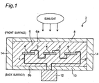
solar cell module 2 is a module configured to convert light energy of sunlight into electric energy. Thesolar cell module 2 is provided as a solar panel on a roof of a building, etc. As shown inFig. 1 , thesolar cell module 2 according to this embodiment includes a plurality of solar cells 4, a plurality ofmetal wirings 5, an enclosinglayer 6, a light-receivingsurface layer 8, aback sheet 10, acollector box 12, and aframe 14. - The solar cells 4 are elements for converting light energy of sunlight into electric energy. The solar cells 4 are made of silicon, for example. The
metal wirings 5 are configured to connect terminals (not shown) of the solar cells 4 to each other. Themetal wirings 5 for connecting the plurality of the solar cells 4 to each other are connected to thecollector box 12 described later. The electric energy generated by the solar cells 4 is supplied to thecollector box 12 via themetal wirings 5. The enclosinglayer 6 is a member that encloses and protects the solar cells 4 and themetal wirings 5. The enclosinglayer 6 is made of a light-transmitting material capable of transmitting sunlight. The material of the enclosinglayer 6 is ethylene-vinyl acetate copolymer (EVA) or PVB (polyvinyl butyral), for example. In this embodiment, EVA is used as the material of the enclosinglayer 6. - As shown in
Fig. 1 , the light-receivingsurface layer 8 and theback sheet 10 are attached to the enclosinglayer 6, being opposite to each other. The light-receivingsurface layer 8 is disposed on one surface (front surface 6a) of the enclosinglayer 6, and theback sheet 10 is disposed on the other surface (back surface 6b) of the enclosinglayer 6. The light-receivingsurface layer 8 is a layer configured to receive sunlight, and constitutes a front surface of thesolar cell module 2. The light-receivingsurface layer 8 is made of a light-transmitting material for transmitting sunlight similarly to the enclosinglayer 6. The material of the light-receivingsurface layer 8 may be a transparent material or a semi-transparent material such as glass and plastic, for example. Theback sheet 10 is a back-surface member of thesolar cell module 2. Thecollector box 12 is bonded and fixed to a back side of theback sheet 10. Thecollector box 12 is a box configured to collect electric energy supplied via themetal wirings 5. Theframe 14 is an outer frame for protecting thesolar cell module 2 from a physical impact. Theframe 14 of this embodiment is fastened by screws in thesolar cell module 2. A material of theframe 14 may be aluminum, iron, or plastic, for example. - The enclosing
layer 6 encloses themetal wirings 5 on a side of theback surface 6b where theback sheet 10 is disposed. On the other hand, theenclosing layer 6 encloses a portion not including themetal wirings 5 on an opposite side of thefront surface 6a where the light-receivingsurface layer 8 is disposed. Therefore, theenclosing layer 6 has the portion of a predetermined thickness from thesurface 6a as a high purity layer not including themetal wirings 5 or the solar cell 4. - Next, a recycling method of recycling the
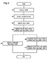
solar cell module 2 having such a structure by separating thesolar cell module 2 into members (materials) will be described with reference toFigs. 2 and3 .Fig. 2 shows a flowchart of the recycling method in this embodiment.Fig. 3 shows a cross-sectional view for explaining the recycling method performed according to the flowchart shown inFig. 2 . - First, the
frame 14 is detached (step S1). More specifically, theframe 14 fastened by screws in thesolar cell module 2 is detached by hand as shown inFig. 3(a) . - Then, the
collector box 12 is detached (step S2). More specifically, thecollector box 12 bonded and fixed to theback sheet 10 is detached by using, for example, a high frequency cutter, as shown inFig. 3(b) . - Then, the
back sheet 10 is removed (step S3: first removing step). More specifically, theback sheet 10 attached to theback surface 6b of theenclosing layer 6 is mechanically removed. For removing theback sheet 10 from thesolar cell module 2 as shown inFig. 3(c) , theback sheet 10 is ground from the back-surface side by using, for example, an NC router grinding machine. "Mechanical removal" refers to removing with use of a mechanical means, and does not cover removing (peeling) by immersion in a solution over time. - The solar cells 4, the
metal wirings 5, and theenclosing layer 6 are removed (step S4: second removing step). More specifically, the solar cells 4, themetal wirings 5, and theenclosing layer 6 are mechanically removed from thesolar cell module 2. For example, by using the same NC router grinding machine as in step S3, the solar cells 4, themetal wirings 5, and theenclosing layer 6 are ground from the back-surface side on which theback sheet 10 is removed. As a result, as shown inFig. 3(d) , the solar cells 4, themetal wirings 5, and theenclosing layer 6 are removed from thesolar cell module 2. As a result, the solar cells 4 and themetal wirings 5 are entirely removed, while theenclosing layer 6 is partially removed. More specifically, theenclosing layer 6 is removed to a depth between the light-receivingsurface layer 8 and the solar cells 4 so that a part of theenclosing layer 6 having a thin thickness (e.g., 0.1 mm) adheres to and remains on the light-receivingsurface layer 8. By removing theenclosing layer 6 to the extent that the light-receivingsurface layer 8 is not ground, the light-receivingsurface layer 8 can be prevented from being damaged by the NC router grinding machine, and thus a reuse value of the light-receivingsurface layer 8 can be increased. The solar cells 4, themetal wirings 5, and theenclosing layer 6 after the removal are collected, and then pulverized at later step S6, and then subjected to specific gravity separation at step S7. - In this way, removing a large portion of the
enclosing layer 6 at step S4 can reduce an amount of peeling liquid used in subsequent step S5. This leads to significant cost reduction especially when the peeling liquid is expensive. Removing all of the solar cells 4 and themetal wirings 5 can remove silicon (that is, the solar cells 4) and metal (that is, the metal wirings 5) which act as factors inhibiting swelling/removing action of the peeling liquid at subsequent step S5. - The removal of the
enclosing layer 6 performed at step S4 in this embodiment is divided into two major stages. More specifically, a first stage is to mechanically remove theenclosing layer 6 from the back-surface side, on which theback sheet 10 is removed, to a depth not reaching the solar cell 4. Subsequently, a second stage is to mechanically remove theenclosing layer 6 which encloses the solar cell 4. According to such a two-staged removing step, theenclosing layer 6 is removed to a depth at which a part of theenclosing layer 6 having a predetermined thickness adheres to and remains on the light-receivingsurface layer 8. Thus, the enclosing layer 6 (enclosing the metal wirings 5) which does not enclose the solar cell 4 can be collected in the first stage, while theenclosing layer 6 which encloses the solar cell 4 can be collected in the second stage. Therefore, theenclosing layer 6 which encloses the solar cell 4 and theenclosing layer 6 which does not enclose the solar cell 4 can be separately collected, and subsequent treatment can be performed to each of the enclosing layers 6 depending on their applications. - Subsequently, the
enclosing layer 6 which adheres to and remains on the light-receivingsurface layer 8 is removed (step S5: third removing step). More specifically, the light-receivingsurface layer 8 together with the adheringenclosing layer 6 is immersed in a predetermined solution (that is, peeling liquid). The peeling liquid may be any liquid that causes swelling and peeling of theenclosing layer 6, such as a neutral peeling agent containing a water-soluble hydrocarbon-based solvent without inflammability, for example. Immersing and swelling theenclosing layer 6 in the peeling liquid generates a shear stress at an interface between theenclosing layer 6 and the light-receivingsurface layer 8. The shear stress leads to peeling and removing of theenclosing layer 6 from the light-receivingsurface layer 8. Further, at step S5, while heating the peeling liquid during the immersion, ultrasonic waves are generated in the peeling liquid. This enhances a penetrating effect and a swelling effect of the peeling liquid to theenclosing layer 6. A total amount of an obtained light-receiving surface layer 8 (e.g., glass) can be collected intact, and theenclosing layer 6 has been removed therefrom to a certain level such that the obtained light-receivingsurface layer 8 can reused with no processing. - The solar cells 4 and the
metal wirings 5 are completely removed at preceding step S4, so theenclosing layer 6 collected at step S5 does not include the solar cells 4 or themetal wirings 5. Therefore, the high-purity enclosing layer 6 can be collected and reused. Particularly, if EVA described above is used as the material of theenclosing layer 6, EVA can be recyclable while it has been considered as not recyclable according to conventional methods. Subsequently, theenclosing layer 6 removed at step S5 is collected. -
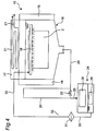
Fig. 4 shows an exemplary apparatus used for immersion into the peeling liquid used at step S5. Theapparatus 15 shown inFig. 4 includes animmersion tank 16 for immersing thesolar cell module 2 therein, an evaporationpreventive lid 17, a coolingwater piping 21, a peeling-liquid supply nozzle 18,ultrasonic irradiation members 19, arecovery line 20, avalve 22, abuffer tank 24, aheater 26, an enclosing-layerrecovery mesh basket 28, aresupply line 30, afilter 31, and apump 32. - The
immersion tank 16 is a tank configured to store the peeling liquid therein for peeling off theenclosing layer 6 from thesolar cell module 2. Thesolar cell module 2 is immersed in the peeling liquid in theimmersion tank 16. The evaporationpreventive lid 17 is a lid for preventing the peeling liquid from evaporating from theimmersion tank 16 to leak out. The evaporationpreventive lid 17 functions as a lid of theimmersion tank 16 by covering an upper side of theimmersion tank 16. The coolingwater piping 21 is a piping that allows a cooling water to flow therein for cooling the peeling liquid which adheres to a lower surface of the evaporationpreventive lid 17. The coolingwater piping 21 penetrates an inside of the evaporationpreventive lid 17. Cooling by the coolingwater piping 21 can condense and liquefy the peeling liquid on the lower surface of the evaporationpreventive lid 17, which was evaporated from theimmersion tank 16, so as to be dropped back into theimmersion tank 16. The peeling-liquid supply nozzle 18 is a member configured to supply a peeling liquid into theimmersion tank 16. The peeling-liquid supply nozzle 18 applies a peeling liquid to thesolar cell module 2 for circulating the peeling liquid in theimmersion tank 16. Theultrasonic irradiation members 19 are configured to apply ultrasonic waves into the peeling liquid in theimmersion tank 16. One of theultrasonic irradiation members 19 is disposed on a side of theimmersion tank 16, while the other is disposed on the other side. Therecovery line 20 is a piping line for recovering (collecting) the peeling liquid used in theimmersion tank 16. Thevalve 22 is a valve for controlling flow of the peeling liquid through therecovery line 20. Thebuffer tank 24 is a tank configured to store the peeling liquid collected from therecovery line 20. Theheater 26 is a means of heating the peeling liquid stored in thebuffer tank 24. The enclosing-layerrecovery mesh basket 28 is configured to collect the removedenclosing layer 6 contained in the peeling liquid sent to thebuffer tank 24. Theresupply line 30 is a piping line for returning and supplying the peeling liquid stored in thebuffer tank 24 and heated by theheater 26 to theimmersion tank 16. Thefilter 31 is a filter for catching impurities in the peeling liquid flowing through theresupply line 30. Thepump 32 is a pump for allowing flow of the peeling liquid through theresupply line 30. - According to the
apparatus 15, thesolar cell module 2 is immersed in the peeling liquid in theimmersion tank 16 with being applied with ultrasonic waves from theultrasonic irradiation part 19 and being applied with a peeling liquid by the peeling-liquid supply nozzle 18. Thepump 32 is operated to cause the used peeling liquid in theimmersion tank 16 to flow through therecovery line 20 to thebuffer tank 24. Theenclosing layer 6 contained in the peeling liquid is caught by the enclosing-layerrecovery mesh basket 28 and the remaining peeling liquid is stored with being heated by theheater 26. The stored peeling liquid is then supplied through theresupply line 30 again to the peeling-liquid supply nozzle 18 by the operation of thepump 32. - In this way, the
enclosing layer 6 of thesolar cell module 2 can be peeled off and removed by the peeling liquid, and the removal of theenclosing layer 6 can continuously be performed while reusing the used peeling liquid. - In this embodiment, the
enclosing layer 6 is then ground at step S5 described above.Step 5 is performed for removing from the light-receivingsurface layer 8 theenclosing layer 6 that remains without being removed by immersion in the peeling liquid. More specifically, the light-receivingsurface layer 8 and theenclosing layer 6 immersed in the peeling liquid are taken out from theimmersion tank 16, and then theenclosing layer 6 is ground by using a grinding means such as a brush. Theenclosing layer 6 is thereby removed from the light-receivingsurface layer 8. In this way, grinding after the removing by the immersion can obtain a removing effect by scrubbing. -
Fig. 5 shows an exemplary apparatus used for grinding at step S5. Anapparatus 34 shown inFig. 5 includes a fixingbase 36 and a grindingbrush 38. The grindingbrush 38 is movable in any directions (e.g., two orthogonal directions) which are parallel to an inclined surface on which thesolar cell module 2 is mounted on the fixingbase 36. According to theapparatus 34, thesolar cell module 2 can be ground by the grindingbrush 38 while being fixed to the fixingbase 36. - In parallel with step S5 of removing the
enclosing layer 6 described above, a step of pulverizing the solar cells 4, themetal wirings 5, and theenclosing layer 6 removed at step S4 is performed (step S6). Although already finely crushed through the mechanical removal at step S4, the solar cells 4, themetal wirings 5, and theenclosing layer 6 will be more finely pulverized by a pulverizing means such as a high-speed mixer. As a result, separation of the solar cells 4, themetal wirings 5, and theenclosing layer 6 which remain integrally with each other can be promoted, and also separation accuracy of specific gravity separation at subsequent step S7 described below can be improved. Furthermore, in this embodiment, pulverization is performed with an alkaline hydrocarbon-based solvent added to the solar cells 4, themetal wirings 5, and theenclosing layer 6. The alkaline hydrocarbon-based solvent has an effect of promoting separation of each of the solar cells 4, themetal wirings 5, and theenclosing layer 6. Performing the pulverization by the high-speed mixer with the alkaline hydrocarbon-based solvent added can accurately separate the solar cells 4, themetal wirings 5, and theenclosing layer 6 during the pulverization. Therefore, separation accuracy of specific gravity separation at subsequent step S7 can further be improved. -
Fig. 6 shows an exemplary apparatus for performing the pulverization at step S6. A pulverizingapparatus 39 shown inFig. 6 includes acontainer 41 and a pulverizing means 43. Thecontainer 41 is configured to house the solar cells 4, themetal wirings 5, and theenclosing layer 6 which was removed at step S4. The pulverizing means 43 is configured to pulverize the solar cells 4, themetal wirings 5, and theenclosing layer 6 in thecontainer 41. The pulverizing means 43 in this embodiment are blades capable of rotating at high speed around an axis extending in the vertical direction. - According to such a configuration, the solar cells 4, the
metal wirings 5, and theenclosing layer 6 in thecontainer 41 can be pulverized by the pulverizing means 43 with the alkaline hydrocarbon-based solvent described above added thereto. - After the pulverizing at step S6, the solar cells 4 and the
metal wirings 5 are separated from the enclosing layer 6 (step S7). The solar cells 4, themetal wirings 5, and theenclosing layer 6 pulverized at step S6 are separately collected and subjected to specific gravity separation for reuse. More specifically, the solar cells 4, themetal wirings 5, and theenclosing layer 6 are immersed in a predetermined solution for specific gravity separation. Unlike the peeling liquid used at step S4, the solution used for the specific gravity separation does not have affinity with theenclosing layer 6 and does not swell theenclosing layer 6. The solar cells 4, themetal wiring 5, and theenclosing layer 6 immersed in the solution are stirred and then left for a predetermined time. As a result, the specific gravity separation progresses so that theenclosing layer 6 having a specific gravity smaller than that of the solution emerges upward in the solution, while the solar cells 4 and themetal wirings 5 having a greater specific gravity sinks downward in the solution. The solution does not have affinity with theenclosing layer 6, and therefore theenclosing layer 6 can be easily separated. As a result, the solar cells 4 / themetal wirings 5 and theenclosing layer 6 can be separated from each other and collected separately. - At step S7, the solution is heated (e.g., at 60 °C or higher) during the specific gravity separation. Heating of the solution leads to expansion of the
enclosing layer 6, and thus an apparent specific gravity of theenclosing layer 6 decreases. The apparent specific gravity of the solution is also reduced by heating, but less reduced than that of theenclosing layer 6. Therefore, a difference in specific gravity between the solution and theenclosing layer 6 will increase so that theenclosing layer 6 easily emerges upwardly. This leads to a shortened time required for the specific gravity separation. -
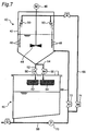
Fig. 7 shows an exemplary apparatus used at step S7. Anapparatus 40 shown inFig. 7 includes a specificgravity separation tank 42, a stirringmember 44, a stirringmotor 46, a plurality ofheaters 48,shower members 50, first andsecond recovery lines second valves recovery tank 60, a lower-layer recovery basket 62, an upper-layer recovery basket 64, first andsecond resupply lines pump 70, and third andfourth valves - The specific
gravity separation tank 42 is configured to immerse the solar cells 4, themetal wirings 5, and theenclosing layer 6 pulverized at step S6 into a solution for specific gravity separation. The stirringmember 44 are blades for stirring the solution in the specificgravity separation tank 42. The stirringmotor 46 is configured to rotate the stirringmember 44. Theheaters 48 are configured to heat the solution in the specificgravity separation tank 42. Theshower members 50 are configured to supply a solution for specific gravity separation into the specificgravity separation tank 42. Theshower members 50 are provided mainly for the purpose of washing off substances (that is, the solar cell 4, themetal wiring 5 and the enclosing layer 6) adhering to an inner side wall of the specificgravity separation tank 42 and theheater 48. Thefirst recovery line 52 is a piping line that allows the solution existing in a lower layer in the specificgravity separation tank 42 to move out of the specificgravity separation tank 42. Thefirst recovery line 52 is provided with thefirst valve 56. Thesecond recovery line 54 is a piping line that allows the solution existing in an upper layer in the specificgravity separation tank 42 to move out of the specificgravity separation tank 42. Thesecond recovery line 54 is provided with thesecond valve 58. For running the solution from the specificgravity separation tank 42 to therecovery tank 60, a control apparatus not shown opens thefirst valve 56 to run the solution through thefirst recovery line 52, and thereafter opens thesecond valve 58 to run the solution through thesecond recovery line 54. Thus, the solution in the lower layer in the specificgravity separation tank 42 is discharged into thefirst recovery line 52, while the solution in the upper layer in the specificgravity separation tank 42 is discharged into thesecond recovery line 54. - The
recovery tank 60 is a tank configured to store the solution collected from the first andsecond recovery lines layer recovery basket 62 is disposed at a position receiving the solution collected from thefirst recovery line 52. The lower-layer recovery basket 62 mainly collects the solar cells 4 and themetal wirings 5 contained as impurities in the solution. The upper-layer recovery basket 64 is disposed at a position receiving the solution collected from thesecond recovery line 54. The upper-layer recovery basket 64 mainly collects theenclosing layer 6 contained as impurities in the solution. Thefirst resupply line 66 is a piping line for supplying and returning the solution stored in therecovery tank 60 to the specificgravity separation tank 42. Thesecond resupply line 68 is a piping line that branches off from thefirst resupply line 66. Thesecond resupply line 68 is configured to supply and return the solution stored in therecovery tank 60 to theshower members 50. Thepump 70 is configured to suck up the solution from therecovery tank 60 into thefirst resupply line 66. Thethird valve 72 is disposed in thefirst resupply line 66, and thefourth valve 74 is disposed in thesecond resupply line 68. - According to the above-described
device 40, the solution in the specificgravity separation tank 42 is stirred by the stirringmember 44, and then left as it is with being heated by theheater 48. Over time, the solar cells 4 and themetal wirings 5 having a high specific gravity has moved to the lower layer of the solution, and theenclosing layer 6 having a low specific gravity has moved to the upper layer of the solution. Thefirst valve 56 is opened to run through thefirst recovery line 52 the solution which existed in the lower layer and contains the solar cells 4 and themetal wirings 5. Then, the solar cells 4 and themetal wirings 5 contained in the solution are caught by the lower-layer recovery basket 62. Subsequently, thefirst valve 56 is closed and thesecond valve 58 is opened to run through thesecond recovery line 54 the solution which existed in the upper layer and contains theenclosing layer 6. Then, theenclosing layer 6 contained in the solution is caught by the upper-layer recovery basket 64. Thepump 70 is operated to run the solution stored in therecovery tank 60 to flow into thefirst resupply line 66. Depending on a solution amount in the specificgravity separation tank 42, opening of thethird valve 72 or thefourth valve 74 is controlled. When thethird valve 72 is opened, the solution will be supplied via thefirst resupply line 66 to the lower layer of the specificgravity separation tank 42. On the other hand, when thefourth valve 74 is opened, the solution will be supplied via thesecond resupply line 68 to theshower members 50 so that theenclosing layer 6, etc. adhering to the inner side wall of the specificgravity separation tank 42 and theheater 48 can be washed off. - In this way, the solar cells 4 and the
metal wirings 5 are separated from theenclosing layer 6 by specific gravity separation using the solution for the specific gravity separation so as to be collected as each material, while the specific gravity separation can continuously be performed with reusing the solution. - The apparatuses shown in
Figs. 4 to 7 are merely examples, so the present invention is not limited to the apparatuses. Any apparatuses that are capable of executing steps described with reference toFigs. 1 to 3 may be used. - Performing steps S1 to S7 described above can dissolve the
solar cell module 2 into each material for reuse. Particularly, at step S4, the solar cells 4 and themetal wirings 5 are entirely removed from thesolar cell module 2, and theenclosing layer 6 is removed to a depth between the light-receivingsurface layer 8 and the solar cells 4 so that the remainingenclosing layer 6 having a predetermined thickness adheres to and remains on the surface of the light-receivingsurface layer 8. Since the solar cells 4 are already entirely removed, it is sufficient to remove only the part of theenclosing layer 6 which adheres to the light-receivingsurface layer 8 at subsequent step S5. Therefore, a time required for immersion treatment in the peeling liquid at step S5 can be extremely shortened, and also an amount of the peeling liquid required for step S5 can be reduced. Further, a removal time at step S5 is significantly shortened, thereby shortening a total processing time. As a result, an overall efficiency of the method of recycling thesolar cell module 2 can be improved. - At step S5, the
enclosing layer 6 is removed not only by immersion in the peeling liquid but also by grinding. Using both immersion and grinding leads to more reliable and efficient removing of theenclosing layer 6. - Furthermore, step S5 and steps S6, S7 can be performed separately in parallel as shown in
Fig. 2 . Performing step S5 and steps S6, S7 in parallel in this way can shorten the total processing time, thereby improving the overall efficiency of the method of recycling thesolar cell module 2. Additionally, the solution used at step S5 is not mixed with the solutions used at steps S6, S7, thereby being reused separately and effectively. More specifically, the peeling liquid (that is, water-soluble hydrocarbon-based solvent) used at step S5, the separation-promoting solution (that is, alkaline hydrocarbon-based solvent) used at step S6, and the solution for specific gravity separation used at step S7 are not mixed with each other, so each of them can repeatedly be used and effectively be reused. - An example related to the above-described method of recycling the
solar cell module 2 according to the embodiment will be described below. - In this example, an experiment was performed in order to observe a state of removal of the
enclosing layer 6 etc. in the samesolar cell module 2 as that of the embodiment, under a process condition described below. Steps S1 and S2 are omitted so that thecollector box 12 and theframe 14 are already removed at the start of the experiment (that is, steps S3 to S7 were performed in this example). -
- Shape of the solar cell module 2: rectangular parallelepiped of 530 mm in width × 620 mm in length × 4.5 mm in thickness
- Thickness of the back sheet 10: 0.3 mm
- Thickness of the enclosing layer 6: 1.0 mm
- Thickness of the solar cells 4: 0.2 mm
- Thickness of the light-receiving surface layer 8: 3.2 mm
- Material of the back sheet 10: mainly composite film of fluorine resin and PET
- Material of the enclosing layer 6: mainly ethylene-vinyl acetate copolymer (EVA)
- Material of the solar cells 4: mainly silicon
- Material of the light-receiving surface layer 8: mainly glass
- First, the
back sheet 10 was ground in several stages by an NC router grinding machine to be removed with a ground amount of each stage set to 0.1 to 0.3 mm (step S3). A total time for the grinding was 15 minutes. The removed backsheet 10 was collected. - Next, the
enclosing layer 6 and the solar cell 4 were ground in several stages by the same NC router grinding machine to be removed with a ground amount of each stage set to 0.1 to 0.3 mm (step S4). As a result, theenclosing layer 6 was ground by a thickness of about 0.9 mm, and the solar cells 4 was entirely ground. A total time for the grinding was 60 minutes. The removedenclosing layer 6 and the solar cells 4 were sucked and collected by a dust collector and then supplied to the pulverizingapparatus 39 shown inFig. 6 (for step S6). On the other hand, the light-receivingsurface layer 8 with theenclosing layer 6 adhering thereto having a thickness of about 0.1mm was supplied to theapparatus 15 shown inFig. 4 (for step S5). - (Step S5) Next, the light-receiving
surface layer 8 with theenclosing layer 6 adhering thereto was immersed in a peeling liquid heated to 80 °C in theapparatus 15 shown inFig. 4 . At this time, ultrasonic waves were applied from theultrasonic irradiation members 19 at frequencies of 38 kHz and 100 kHz switched every three minutes to promote removal. After immersing for about 5 to 30 minutes, the light-receivingsurface layer 8 was pulled up from theimmersion tank 16, and liquid draining was performed to the light-receivingsurface layer 8 for about 5 minutes. Then, the light-receivingsurface layer 8 was supplied to theapparatus 34 shown inFig. 5 to be ground by the grindingbrush 38. Theenclosing layer 6 ground and removed from the light-receivingsurface layer 8 was collected. - (Step S6) The
enclosing layer 6 and the solar cells 4 ground by the NC router grinding machine and collected by the dust collector were stored in thecontainer 41 in the pulverizingapparatus 39 shown inFig. 6 to be added with a predetermined amount of the alkaline hydrocarbon-based solvent. The pulverizing means 43 was rotated at a rotational speed of 18000 to 20000 rpm to pulverize theenclosing layer 6 and the solar cells 4 for about 1 minute to make them finer. - (Step S7) Next, the pulverized
enclosing layer 6 and the solar cells 4 were immersed in a solution heated to 80 °C in the specificgravity separation tank 42 in theapparatus 40 shown inFig. 7 . The pulverizedenclosing layer 6 and the solar cells 4 were stirred with the stirringmember 44 at 100 rpm for about 1 minute and then left in the solution for about 10 minutes for the specific gravity separation. Draining the lower layer of the solution to the lower-layer recovery basket 62 and draining the upper layer of the solution to the upper-layer recovery basket 64, thereby collecting silicon (that is, the solar cells 4) and metals (that is, the metal wirings 5) by the lower-layer recovery basket 62 and collecting theenclosing layer 6 by the upper-layer recovery basket 64. The collected materials were disposed in a vat to and then dried with a dryer etc. - According to the example, one
solar cell module 2 was processed such that the solar cells 4 and themetal wirings 5 were separated from theenclosing layer 6 with high accuracy. Particularly, at step S5 of removing theenclosing layer 6, the highly-pure enclosing layer 6 with very few impurities was collected. Furthermore, step S5 was completed for about 30 minutes while the conventional method takes several hours to several tens of hours, thereby achieving a significantly shortened total processing time. As a result, the overall efficiency for the method of recycling thesolar cell module 2 was improved dramatically. Furthermore, a large portion of theenclosing layer 6 was mechanically removed at step S4 before step S5, so an amount of the peeling liquid used at step S5 for peeling and removing the remainingenclosing layer 6 was reduced significantly. Thus, escaping of the expensive peeling liquid outside a system was reduced and a significant cost reduction was achieved. - The present invention is not limited to the embodiment and can be implemented in various other forms. For example, step S5 uses the brush (that is, the grinding brush 38) for grinding, but not limited thereto the
enclosing layer 6 may be scraped off by a means with edge such as a knife, or may be ground by any grinding means such as steel wool, a spatula rubber roll, etc. S5 performs the grinding in the embodiment, but not limited thereto may perform only the immersion using the immersion liquid instead of the grinding. - In the embodiment, ethylene-vinyl acetate copolymer (EVA) is exemplified as the material of the
enclosing layer 6, but the present invention is not limited thereto. For example, any materials that are capable of enclosing the solar cells 4 and themetal wirings 5 and transmitting sunlight may be used, including PVB (polyvinyl butyral). - In the embodiment, the solar cells 4 and the enclosing layers 6 are pulverized by the high-speed mixer at step S6 before step S7, but not limited thereto specific gravity separation may be performed to them without involving the pulverization.
- By properly combining any of the aforementioned various embodiments, the effects possessed by them can be produced.
- The present invention is applicable to a method of recycling a solar cell module including an enclosing layer that encloses a solar cell therein, a light-receiving surface layer laminated on the enclosing layer, and a back sheet laminated on the enclosing layer to be opposite to the light-receiving surface layer.
- The present invention has sufficiently been described in relation to the preferred embodiment with reference to the accompanying drawings, but various changes and modifications thereof are apparent for those skilled in the art. Such changes and modifications should be understood to be encompassed therein as far as not departing from the scope of the present invention described in the appended claims.
- The disclosed contents of the specification, the drawings, and the claims of Japanese Patent Application No.
2015-185738 filed on September 18, 2015
Claims (9)
- A method of recycling a solar cell module comprising an enclosing layer that encloses a solar cell therein, a light-receiving surface layer laminated on one surface of the enclosing layer, and a back sheet laminated on the other surface of the enclosing layer, the method comprising:a first removing step of mechanically removing the back sheet;a second removing step of mechanically removing from a side on which the back sheet is removed the entire solar cell and the enclosing layer to such a depth that a part of the enclosing layer having a predetermined thickness remains on the light-receiving surface layer, after the first removing step; anda third removing step of removing the part of the enclosing layer remaining on the light-receiving surface layer by immersion in a solution that causes swelling of the enclosing layer, after the second removing step.
- The method of recycling a solar cell module according to claim 1, wherein the third removing step performs grinding after the immersion in the solution for removing the enclosing layer remaining on the light-receiving surface layer.
- The method of recycling a solar cell module according to claim 2, wherein the third removing step uses a brush for the grinding.
- The method of recycling a solar cell module according to any one of claims 1 to 3, further comprising
a pulverizing step of pulverizing the solar cell and the enclosing layer removed by the second removing step, and
a separating step of separating the pulverized solar cell and the pulverized enclosing layer from each other using specific gravity separation by immersing them in a solution. - The method of recycling a solar cell module according to claim 4, wherein an alkaline hydrocarbon-based solvent is applied to the solar cell and the enclosing layer in the pulverizing step.
- The method of recycling a solar cell module according to claim 4 or 5, wherein the solution used in the separating step has a change rate of specific gravity associated with temperature increase, the change rate being smaller than that of the enclosing layer.
- The method of recycling a solar cell module according to any one of claims 1 to 6, wherein the second removing step performs a step of mechanically removing the enclosing layer to a depth not reaching the solar cell from the side on which the back sheet is removed, and separately performs a step of mechanically removing the remaining enclosing layer enclosing the solar cell.
- The method of recycling a solar cell module according to any one of claims 1 to 7, wherein the solution used in the third removing step is a neutral peeling agent containing a water-soluble hydrocarbon-based solvent.
- The method of recycling a solar cell module according to any one of claims 1 to 8, wherein the enclosing layer is made of an ethylene-vinyl acetate copolymer.
Applications Claiming Priority (2)
| Application Number | Priority Date | Filing Date | Title |
|---|---|---|---|
| JP2015185738 | 2015-09-18 | ||
| PCT/JP2016/077584 WO2017047802A1 (en) | 2015-09-18 | 2016-09-16 | Recycling method for solar battery module |
Publications (3)
| Publication Number | Publication Date |
|---|---|
| EP3352227A1 true EP3352227A1 (en) | 2018-07-25 |
| EP3352227A4 EP3352227A4 (en) | 2019-05-15 |
| EP3352227B1 EP3352227B1 (en) | 2020-03-25 |
Family
ID=58289520
Family Applications (1)
| Application Number | Title | Priority Date | Filing Date |
|---|---|---|---|
| EP16846673.8A Active EP3352227B1 (en) | 2015-09-18 | 2016-09-16 | Recycling method for solar battery module |
Country Status (5)
| Country | Link |
|---|---|
| US (1) | US10388812B2 (en) |
| EP (1) | EP3352227B1 (en) |
| JP (1) | JP6599469B2 (en) |
| CN (1) | CN108352418B (en) |
| WO (1) | WO2017047802A1 (en) |
Cited By (2)
| Publication number | Priority date | Publication date | Assignee | Title |
|---|---|---|---|---|
| EP4159397A1 (en) | 2021-10-04 | 2023-04-05 | Commissariat À L'Énergie Atomique Et Aux Énergies Alternatives | Processing method and installation for recycling a photovoltaic module |
| WO2023222415A1 (en) * | 2022-05-17 | 2023-11-23 | SOLAR MATERIALS GmbH | Method and device for processing solar modules |
Families Citing this family (10)
| Publication number | Priority date | Publication date | Assignee | Title |
|---|---|---|---|---|
| JP6517174B2 (en) * | 2016-08-01 | 2019-05-22 | 東芝環境ソリューション株式会社 | How to recycle solar cell modules |
| JP7296947B2 (en) * | 2018-04-19 | 2023-06-23 | ソーラーフロンティア株式会社 | METHOD AND APPARATUS FOR RECYCLING SOLAR MODULE |
| CN109570195B (en) * | 2018-11-27 | 2021-07-30 | 河海大学常州校区 | Separation and recovery method of double-glass structure assembly |
| JPWO2021090695A1 (en) * | 2019-11-06 | 2021-05-14 | ||
| US11931783B2 (en) | 2019-11-08 | 2024-03-19 | Industrial Technology Research Institute | Recycle apparatus for photovoltaic module |
| JP6905103B1 (en) * | 2020-01-24 | 2021-07-21 | Dowaエコシステム株式会社 | Metal recovery method |
| KR102178024B1 (en) * | 2020-02-11 | 2020-11-12 | 박일남 | Gas separation capture equipment for photovoltaic waste module |
| CN112058871B (en) * | 2020-09-03 | 2021-12-28 | 河北大学 | Apparatus and method for disassembling solar cell module |
| CN114634643B (en) * | 2020-12-01 | 2024-03-19 | 财团法人工业技术研究院 | Swelling agent and plate structure recovery method using same |
| TWI798636B (en) * | 2021-02-04 | 2023-04-11 | 國立臺南大學 | Solar cell module recovery planing equipment and its planing recovery method |
Family Cites Families (18)
| Publication number | Priority date | Publication date | Assignee | Title |
|---|---|---|---|---|
| DE2638270C2 (en) * | 1976-08-25 | 1983-01-27 | Wacker-Chemitronic Gesellschaft für Elektronik-Grundstoffe mbH, 8263 Burghausen | Process for the production of large, self-supporting plates made of silicon |
| JPH11330345A (en) * | 1998-05-12 | 1999-11-30 | Sony Corp | Method for removing burr |
| US6063995A (en) * | 1998-07-16 | 2000-05-16 | First Solar, Llc | Recycling silicon photovoltaic modules |
| CN100481524C (en) * | 2003-09-10 | 2009-04-22 | 大日本印刷株式会社 | Encapsulant layer for solar battery assembly and solar battery assembly |
| JP2006179626A (en) * | 2004-12-22 | 2006-07-06 | Showa Shell Sekiyu Kk | Cis system thin film solar cell module, and its manufacturing method and separation method |
| JP2007134358A (en) * | 2005-11-08 | 2007-05-31 | Kyowa Hakko Chemical Co Ltd | Method for recovering solar battery cell and/or reinforced glass from solar cell module |
| JP4738167B2 (en) * | 2005-12-26 | 2011-08-03 | 京セラ株式会社 | Disassembly method of solar cell module |
| JP2009214058A (en) * | 2008-03-12 | 2009-09-24 | Sharp Corp | Disassembling method of solar cell module |
| US20110186779A1 (en) * | 2008-08-13 | 2011-08-04 | John Bohland | Photovoltaic module recycling |
| JP2011109003A (en) * | 2009-11-20 | 2011-06-02 | Sharp Corp | Method of removing solar cell and transparent resin from transparent substrate, and solar cell module |
| CN102791647B (en) * | 2010-03-08 | 2015-04-08 | 旭硝子株式会社 | Method for eliminating resin film and method for producing laminate |
| JP2012019134A (en) * | 2010-07-09 | 2012-01-26 | Takio Ishiguro | Recovery method for reuse of solar battery module material |
| DE102011000322A1 (en) * | 2011-01-25 | 2012-07-26 | saperatec GmbH | Separating medium, method and system for separating multilayer systems |
| CN102544239B (en) * | 2012-03-07 | 2014-03-12 | 英利集团有限公司 | Method and device for decomposing and recycling photovoltaic component |
| JP5938309B2 (en) * | 2012-09-12 | 2016-06-22 | 東芝環境ソリューション株式会社 | How to recycle solar panels |
| JP6068948B2 (en) * | 2012-11-27 | 2017-01-25 | 横浜油脂工業株式会社 | Recycling method of solar cell module |
| FR3017551B1 (en) * | 2014-02-20 | 2016-03-11 | Recyclage Valorisation Photovoltaique R V P | METHOD AND INSTALLATION FOR RECYCLING PHOTOVOLTAIC PANELS |
| FR3040704B1 (en) * | 2015-09-03 | 2021-09-10 | Centre Nat Rech Scient | METHOD AND DEVICE FOR DISMANTLING MULTI-LAYER SYSTEMS INCLUDING AT LEAST ONE ORGANIC COMPONENT |
-
2016
- 2016-09-16 US US15/760,805 patent/US10388812B2/en active Active
- 2016-09-16 WO PCT/JP2016/077584 patent/WO2017047802A1/en active Application Filing
- 2016-09-16 CN CN201680053952.7A patent/CN108352418B/en active Active
- 2016-09-16 EP EP16846673.8A patent/EP3352227B1/en active Active
- 2016-09-16 JP JP2017540037A patent/JP6599469B2/en active Active
Cited By (3)
| Publication number | Priority date | Publication date | Assignee | Title |
|---|---|---|---|---|
| EP4159397A1 (en) | 2021-10-04 | 2023-04-05 | Commissariat À L'Énergie Atomique Et Aux Énergies Alternatives | Processing method and installation for recycling a photovoltaic module |
| FR3127710A1 (en) * | 2021-10-04 | 2023-04-07 | Commissariat à l'Energie Atomique et aux Energies Alternatives | Treatment method for recycling a photovoltaic module |
| WO2023222415A1 (en) * | 2022-05-17 | 2023-11-23 | SOLAR MATERIALS GmbH | Method and device for processing solar modules |
Also Published As
| Publication number | Publication date |
|---|---|
| EP3352227A4 (en) | 2019-05-15 |
| CN108352418A (en) | 2018-07-31 |
| WO2017047802A1 (en) | 2017-03-23 |
| US10388812B2 (en) | 2019-08-20 |
| EP3352227B1 (en) | 2020-03-25 |
| CN108352418B (en) | 2021-11-02 |
| JP6599469B2 (en) | 2019-10-30 |
| JPWO2017047802A1 (en) | 2018-07-19 |
| US20180254364A1 (en) | 2018-09-06 |
Similar Documents
| Publication | Publication Date | Title |
|---|---|---|
| US10388812B2 (en) | Method of recycling solar cell module | |
| RU2722104C2 (en) | Method and device for separation of multilayer systems containing at least one organic component | |
| JP6068948B2 (en) | Recycling method of solar cell module | |
| DK2668226T3 (en) | Separation medium, method and plant for separating multilayer systems | |
| JP2018176002A (en) | Recovery method and recovery device of plate glass of solar battery module | |
| JP2012019134A (en) | Recovery method for reuse of solar battery module material | |
| CN109585272A (en) | A kind of silicon wafer cleaning method improving photoelectric efficiency | |
| CN102806525B (en) | The minimizing technology of burnishing device and polishing accessory substance | |
| CN202162167U (en) | Acid soaking device for silicon material | |
| CN207371156U (en) | A kind of mechanical normal pressure defoaming device | |
| JP7368036B1 (en) | Deinking device | |
| CN111530834B (en) | Cleaning and deoiling equipment for screw machining | |
| CN103413856B (en) | Remove the method for residual silica gel on junction box body | |
| CN102698989A (en) | Method for precleaning silicon wafer | |
| Palaniappan et al. | Recycling of Solar Panels | |
| CN101982870B (en) | Method for protecting chip in chip thinning process | |
| JP2013202421A (en) | Method for recovering glass material | |
| CN114919270A (en) | Solar lamination stripping off device | |
| KR102504453B1 (en) | Component separation device and method for solar module recycling | |
| JP2007134358A (en) | Method for recovering solar battery cell and/or reinforced glass from solar cell module | |
| CN203212359U (en) | Oil skimming device capable of recycling offshore thin oil slick | |
| JP2008071783A (en) | Resist stripping apparatus and method | |
| CN109687050A (en) | High efficiency battery recycling method | |
| CN203816796U (en) | Wool yolk recycling centrifugal device used for wool washing machine | |
| CN218746887U (en) | Numerical control grinding machine |
Legal Events
| Date | Code | Title | Description |
|---|---|---|---|
| STAA | Information on the status of an ep patent application or granted ep patent |
Free format text: STATUS: THE INTERNATIONAL PUBLICATION HAS BEEN MADE |
|
| PUAI | Public reference made under article 153(3) epc to a published international application that has entered the european phase |
Free format text: ORIGINAL CODE: 0009012 |
|
| STAA | Information on the status of an ep patent application or granted ep patent |
Free format text: STATUS: REQUEST FOR EXAMINATION WAS MADE |
|
| 17P | Request for examination filed |
Effective date: 20180316 |
|
| AK | Designated contracting states |
Kind code of ref document: A1 Designated state(s): AL AT BE BG CH CY CZ DE DK EE ES FI FR GB GR HR HU IE IS IT LI LT LU LV MC MK MT NL NO PL PT RO RS SE SI SK SM TR |
|
| AX | Request for extension of the european patent |
Extension state: BA ME |
|
| DAV | Request for validation of the european patent (deleted) | ||
| DAX | Request for extension of the european patent (deleted) | ||
| A4 | Supplementary search report drawn up and despatched |
Effective date: 20190416 |
|
| RIC1 | Information provided on ipc code assigned before grant |
Ipc: B29B 17/02 20060101ALI20190410BHEP Ipc: B09B 3/00 20060101AFI20190410BHEP Ipc: H01L 31/049 20140101ALI20190410BHEP Ipc: B32B 38/10 20060101ALI20190410BHEP Ipc: C08J 11/06 20060101ALI20190410BHEP Ipc: H01L 31/042 20140101ALI20190410BHEP Ipc: H01L 31/18 20060101ALI20190410BHEP Ipc: B09B 5/00 20060101ALI20190410BHEP Ipc: B32B 43/00 20060101ALI20190410BHEP Ipc: C08L 23/08 20060101ALI20190410BHEP |
|
| REG | Reference to a national code |
Ref country code: DE Ref legal event code: R079 Ref document number: 602016032733 Country of ref document: DE Free format text: PREVIOUS MAIN CLASS: H01L0031042000 Ipc: B09B0003000000 |
|
| GRAP | Despatch of communication of intention to grant a patent |
Free format text: ORIGINAL CODE: EPIDOSNIGR1 |
|
| STAA | Information on the status of an ep patent application or granted ep patent |
Free format text: STATUS: GRANT OF PATENT IS INTENDED |
|
| RIC1 | Information provided on ipc code assigned before grant |
Ipc: H01L 31/18 20060101ALI20191121BHEP Ipc: B29B 17/02 20060101ALI20191121BHEP Ipc: B09B 3/00 20060101AFI20191121BHEP Ipc: H01L 31/042 20140101ALI20191121BHEP Ipc: H01L 31/049 20140101ALI20191121BHEP Ipc: B32B 38/10 20060101ALI20191121BHEP Ipc: C08J 11/06 20060101ALI20191121BHEP Ipc: B32B 43/00 20060101ALI20191121BHEP Ipc: H01L 31/048 20140101ALI20191121BHEP Ipc: C08L 23/08 20060101ALI20191121BHEP Ipc: B09B 5/00 20060101ALI20191121BHEP |
|
| INTG | Intention to grant announced |
Effective date: 20191205 |
|
| GRAS | Grant fee paid |
Free format text: ORIGINAL CODE: EPIDOSNIGR3 |
|
| GRAA | (expected) grant |
Free format text: ORIGINAL CODE: 0009210 |
|
| STAA | Information on the status of an ep patent application or granted ep patent |
Free format text: STATUS: THE PATENT HAS BEEN GRANTED |
|
| AK | Designated contracting states |
Kind code of ref document: B1 Designated state(s): AL AT BE BG CH CY CZ DE DK EE ES FI FR GB GR HR HU IE IS IT LI LT LU LV MC MK MT NL NO PL PT RO RS SE SI SK SM TR |
|
| REG | Reference to a national code |
Ref country code: GB Ref legal event code: FG4D |
|
| REG | Reference to a national code |
Ref country code: AT Ref legal event code: REF Ref document number: 1247987 Country of ref document: AT Kind code of ref document: T Effective date: 20200415 Ref country code: IE Ref legal event code: FG4D |
|
| REG | Reference to a national code |
Ref country code: DE Ref legal event code: R096 Ref document number: 602016032733 Country of ref document: DE |
|
| PG25 | Lapsed in a contracting state [announced via postgrant information from national office to epo] |
Ref country code: FI Free format text: LAPSE BECAUSE OF FAILURE TO SUBMIT A TRANSLATION OF THE DESCRIPTION OR TO PAY THE FEE WITHIN THE PRESCRIBED TIME-LIMIT Effective date: 20200325 Ref country code: RS Free format text: LAPSE BECAUSE OF FAILURE TO SUBMIT A TRANSLATION OF THE DESCRIPTION OR TO PAY THE FEE WITHIN THE PRESCRIBED TIME-LIMIT Effective date: 20200325 Ref country code: NO Free format text: LAPSE BECAUSE OF FAILURE TO SUBMIT A TRANSLATION OF THE DESCRIPTION OR TO PAY THE FEE WITHIN THE PRESCRIBED TIME-LIMIT Effective date: 20200625 |
|
| PG25 | Lapsed in a contracting state [announced via postgrant information from national office to epo] |
Ref country code: BG Free format text: LAPSE BECAUSE OF FAILURE TO SUBMIT A TRANSLATION OF THE DESCRIPTION OR TO PAY THE FEE WITHIN THE PRESCRIBED TIME-LIMIT Effective date: 20200625 Ref country code: SE Free format text: LAPSE BECAUSE OF FAILURE TO SUBMIT A TRANSLATION OF THE DESCRIPTION OR TO PAY THE FEE WITHIN THE PRESCRIBED TIME-LIMIT Effective date: 20200325 Ref country code: LV Free format text: LAPSE BECAUSE OF FAILURE TO SUBMIT A TRANSLATION OF THE DESCRIPTION OR TO PAY THE FEE WITHIN THE PRESCRIBED TIME-LIMIT Effective date: 20200325 Ref country code: GR Free format text: LAPSE BECAUSE OF FAILURE TO SUBMIT A TRANSLATION OF THE DESCRIPTION OR TO PAY THE FEE WITHIN THE PRESCRIBED TIME-LIMIT Effective date: 20200626 Ref country code: HR Free format text: LAPSE BECAUSE OF FAILURE TO SUBMIT A TRANSLATION OF THE DESCRIPTION OR TO PAY THE FEE WITHIN THE PRESCRIBED TIME-LIMIT Effective date: 20200325 |
|
| REG | Reference to a national code |
Ref country code: NL Ref legal event code: MP Effective date: 20200325 |
|
| REG | Reference to a national code |
Ref country code: LT Ref legal event code: MG4D |
|
| PG25 | Lapsed in a contracting state [announced via postgrant information from national office to epo] |
Ref country code: NL Free format text: LAPSE BECAUSE OF FAILURE TO SUBMIT A TRANSLATION OF THE DESCRIPTION OR TO PAY THE FEE WITHIN THE PRESCRIBED TIME-LIMIT Effective date: 20200325 |
|
| PG25 | Lapsed in a contracting state [announced via postgrant information from national office to epo] |
Ref country code: IS Free format text: LAPSE BECAUSE OF FAILURE TO SUBMIT A TRANSLATION OF THE DESCRIPTION OR TO PAY THE FEE WITHIN THE PRESCRIBED TIME-LIMIT Effective date: 20200725 Ref country code: SK Free format text: LAPSE BECAUSE OF FAILURE TO SUBMIT A TRANSLATION OF THE DESCRIPTION OR TO PAY THE FEE WITHIN THE PRESCRIBED TIME-LIMIT Effective date: 20200325 Ref country code: RO Free format text: LAPSE BECAUSE OF FAILURE TO SUBMIT A TRANSLATION OF THE DESCRIPTION OR TO PAY THE FEE WITHIN THE PRESCRIBED TIME-LIMIT Effective date: 20200325 Ref country code: SM Free format text: LAPSE BECAUSE OF FAILURE TO SUBMIT A TRANSLATION OF THE DESCRIPTION OR TO PAY THE FEE WITHIN THE PRESCRIBED TIME-LIMIT Effective date: 20200325 Ref country code: EE Free format text: LAPSE BECAUSE OF FAILURE TO SUBMIT A TRANSLATION OF THE DESCRIPTION OR TO PAY THE FEE WITHIN THE PRESCRIBED TIME-LIMIT Effective date: 20200325 Ref country code: CZ Free format text: LAPSE BECAUSE OF FAILURE TO SUBMIT A TRANSLATION OF THE DESCRIPTION OR TO PAY THE FEE WITHIN THE PRESCRIBED TIME-LIMIT Effective date: 20200325 Ref country code: PT Free format text: LAPSE BECAUSE OF FAILURE TO SUBMIT A TRANSLATION OF THE DESCRIPTION OR TO PAY THE FEE WITHIN THE PRESCRIBED TIME-LIMIT Effective date: 20200818 Ref country code: LT Free format text: LAPSE BECAUSE OF FAILURE TO SUBMIT A TRANSLATION OF THE DESCRIPTION OR TO PAY THE FEE WITHIN THE PRESCRIBED TIME-LIMIT Effective date: 20200325 |
|
| REG | Reference to a national code |
Ref country code: AT Ref legal event code: MK05 Ref document number: 1247987 Country of ref document: AT Kind code of ref document: T Effective date: 20200325 |
|
| REG | Reference to a national code |
Ref country code: DE Ref legal event code: R097 Ref document number: 602016032733 Country of ref document: DE |
|
| PG25 | Lapsed in a contracting state [announced via postgrant information from national office to epo] |
Ref country code: AT Free format text: LAPSE BECAUSE OF FAILURE TO SUBMIT A TRANSLATION OF THE DESCRIPTION OR TO PAY THE FEE WITHIN THE PRESCRIBED TIME-LIMIT Effective date: 20200325 Ref country code: IT Free format text: LAPSE BECAUSE OF FAILURE TO SUBMIT A TRANSLATION OF THE DESCRIPTION OR TO PAY THE FEE WITHIN THE PRESCRIBED TIME-LIMIT Effective date: 20200325 Ref country code: DK Free format text: LAPSE BECAUSE OF FAILURE TO SUBMIT A TRANSLATION OF THE DESCRIPTION OR TO PAY THE FEE WITHIN THE PRESCRIBED TIME-LIMIT Effective date: 20200325 Ref country code: ES Free format text: LAPSE BECAUSE OF FAILURE TO SUBMIT A TRANSLATION OF THE DESCRIPTION OR TO PAY THE FEE WITHIN THE PRESCRIBED TIME-LIMIT Effective date: 20200325 |
|
| PLBE | No opposition filed within time limit |
Free format text: ORIGINAL CODE: 0009261 |
|
| STAA | Information on the status of an ep patent application or granted ep patent |
Free format text: STATUS: NO OPPOSITION FILED WITHIN TIME LIMIT |
|
| PG25 | Lapsed in a contracting state [announced via postgrant information from national office to epo] |
Ref country code: PL Free format text: LAPSE BECAUSE OF FAILURE TO SUBMIT A TRANSLATION OF THE DESCRIPTION OR TO PAY THE FEE WITHIN THE PRESCRIBED TIME-LIMIT Effective date: 20200325 |
|
| 26N | No opposition filed |
Effective date: 20210112 |
|
| REG | Reference to a national code |
Ref country code: CH Ref legal event code: PL |
|
| GBPC | Gb: european patent ceased through non-payment of renewal fee |
Effective date: 20200916 |
|
| PG25 | Lapsed in a contracting state [announced via postgrant information from national office to epo] |
Ref country code: SI Free format text: LAPSE BECAUSE OF FAILURE TO SUBMIT A TRANSLATION OF THE DESCRIPTION OR TO PAY THE FEE WITHIN THE PRESCRIBED TIME-LIMIT Effective date: 20200325 |
|
| REG | Reference to a national code |
Ref country code: BE Ref legal event code: MM Effective date: 20200930 |
|
| PG25 | Lapsed in a contracting state [announced via postgrant information from national office to epo] |
Ref country code: LU Free format text: LAPSE BECAUSE OF NON-PAYMENT OF DUE FEES Effective date: 20200916 |
|
| PG25 | Lapsed in a contracting state [announced via postgrant information from national office to epo] |
Ref country code: FR Free format text: LAPSE BECAUSE OF NON-PAYMENT OF DUE FEES Effective date: 20200930 |
|
| PG25 | Lapsed in a contracting state [announced via postgrant information from national office to epo] |
Ref country code: BE Free format text: LAPSE BECAUSE OF NON-PAYMENT OF DUE FEES Effective date: 20200930 Ref country code: CH Free format text: LAPSE BECAUSE OF NON-PAYMENT OF DUE FEES Effective date: 20200930 Ref country code: IE Free format text: LAPSE BECAUSE OF NON-PAYMENT OF DUE FEES Effective date: 20200916 Ref country code: LI Free format text: LAPSE BECAUSE OF NON-PAYMENT OF DUE FEES Effective date: 20200930 Ref country code: GB Free format text: LAPSE BECAUSE OF NON-PAYMENT OF DUE FEES Effective date: 20200916 |
|
| PG25 | Lapsed in a contracting state [announced via postgrant information from national office to epo] |
Ref country code: TR Free format text: LAPSE BECAUSE OF FAILURE TO SUBMIT A TRANSLATION OF THE DESCRIPTION OR TO PAY THE FEE WITHIN THE PRESCRIBED TIME-LIMIT Effective date: 20200325 Ref country code: MT Free format text: LAPSE BECAUSE OF FAILURE TO SUBMIT A TRANSLATION OF THE DESCRIPTION OR TO PAY THE FEE WITHIN THE PRESCRIBED TIME-LIMIT Effective date: 20200325 Ref country code: CY Free format text: LAPSE BECAUSE OF FAILURE TO SUBMIT A TRANSLATION OF THE DESCRIPTION OR TO PAY THE FEE WITHIN THE PRESCRIBED TIME-LIMIT Effective date: 20200325 |
|
| PG25 | Lapsed in a contracting state [announced via postgrant information from national office to epo] |
Ref country code: MK Free format text: LAPSE BECAUSE OF FAILURE TO SUBMIT A TRANSLATION OF THE DESCRIPTION OR TO PAY THE FEE WITHIN THE PRESCRIBED TIME-LIMIT Effective date: 20200325 Ref country code: MC Free format text: LAPSE BECAUSE OF FAILURE TO SUBMIT A TRANSLATION OF THE DESCRIPTION OR TO PAY THE FEE WITHIN THE PRESCRIBED TIME-LIMIT Effective date: 20200325 Ref country code: AL Free format text: LAPSE BECAUSE OF FAILURE TO SUBMIT A TRANSLATION OF THE DESCRIPTION OR TO PAY THE FEE WITHIN THE PRESCRIBED TIME-LIMIT Effective date: 20200325 |
|
| PGFP | Annual fee paid to national office [announced via postgrant information from national office to epo] |
Ref country code: DE Payment date: 20230615 Year of fee payment: 8 |
|
| REG | Reference to a national code |
Ref country code: DE Ref legal event code: R081 Ref document number: 602016032733 Country of ref document: DE Owner name: DAIKIN INDUSTRIES, LTD., JP Free format text: FORMER OWNERS: TOHO KASEI CO., LTD., YAMATOKORIYAMA, JP; DAIKIN INDUSTRIES, LTD., OSAKA-SHI, JP Ref country code: DE Ref legal event code: R081 Ref document number: 602016032733 Country of ref document: DE Owner name: DAIKIN FINETECH, LTD., YAMATOKORIYAMA-SHI, JP Free format text: FORMER OWNERS: TOHO KASEI CO., LTD., YAMATOKORIYAMA, JP; DAIKIN INDUSTRIES, LTD., OSAKA-SHI, JP |