EP3352034A1 - Classification of gas turbine engine components - Google Patents
Classification of gas turbine engine components Download PDFInfo
- Publication number
- EP3352034A1 EP3352034A1 EP18153078.3A EP18153078A EP3352034A1 EP 3352034 A1 EP3352034 A1 EP 3352034A1 EP 18153078 A EP18153078 A EP 18153078A EP 3352034 A1 EP3352034 A1 EP 3352034A1
- Authority
- EP
- European Patent Office
- Prior art keywords
- components
- set forth
- category
- aircraft
- gas turbine
- Prior art date
- Legal status (The legal status is an assumption and is not a legal conclusion. Google has not performed a legal analysis and makes no representation as to the accuracy of the status listed.)
- Granted
Links
- 238000000034 method Methods 0.000 claims abstract description 18
- 238000004519 manufacturing process Methods 0.000 claims abstract description 7
- 230000010006 flight Effects 0.000 claims description 17
- 238000001816 cooling Methods 0.000 claims description 15
- 239000011248 coating agent Substances 0.000 claims description 14
- 238000000576 coating method Methods 0.000 claims description 14
- 239000002245 particle Substances 0.000 claims description 4
- 239000000446 fuel Substances 0.000 description 6
- 238000004891 communication Methods 0.000 description 3
- 230000009467 reduction Effects 0.000 description 2
- 230000003068 static effect Effects 0.000 description 2
- 230000008901 benefit Effects 0.000 description 1
- 230000008859 change Effects 0.000 description 1
- 238000007635 classification algorithm Methods 0.000 description 1
- 238000002485 combustion reaction Methods 0.000 description 1
- 230000006835 compression Effects 0.000 description 1
- 238000007906 compression Methods 0.000 description 1
- 238000012937 correction Methods 0.000 description 1
- 239000011888 foil Substances 0.000 description 1
- 230000033001 locomotion Effects 0.000 description 1
- 238000012423 maintenance Methods 0.000 description 1
- 230000007246 mechanism Effects 0.000 description 1
- 238000012986 modification Methods 0.000 description 1
- 230000004048 modification Effects 0.000 description 1
- 230000004044 response Effects 0.000 description 1
Images

Classifications
-
- G—PHYSICS
- G06—COMPUTING; CALCULATING OR COUNTING
- G06F—ELECTRIC DIGITAL DATA PROCESSING
- G06F30/00—Computer-aided design [CAD]
- G06F30/10—Geometric CAD
- G06F30/15—Vehicle, aircraft or watercraft design
-
- G—PHYSICS
- G06—COMPUTING; CALCULATING OR COUNTING
- G06Q—INFORMATION AND COMMUNICATION TECHNOLOGY [ICT] SPECIALLY ADAPTED FOR ADMINISTRATIVE, COMMERCIAL, FINANCIAL, MANAGERIAL OR SUPERVISORY PURPOSES; SYSTEMS OR METHODS SPECIALLY ADAPTED FOR ADMINISTRATIVE, COMMERCIAL, FINANCIAL, MANAGERIAL OR SUPERVISORY PURPOSES, NOT OTHERWISE PROVIDED FOR
- G06Q50/00—Information and communication technology [ICT] specially adapted for implementation of business processes of specific business sectors, e.g. utilities or tourism
- G06Q50/04—Manufacturing
-
- G—PHYSICS
- G01—MEASURING; TESTING
- G01M—TESTING STATIC OR DYNAMIC BALANCE OF MACHINES OR STRUCTURES; TESTING OF STRUCTURES OR APPARATUS, NOT OTHERWISE PROVIDED FOR
- G01M15/00—Testing of engines
- G01M15/14—Testing gas-turbine engines or jet-propulsion engines
-
- G—PHYSICS
- G01—MEASURING; TESTING
- G01M—TESTING STATIC OR DYNAMIC BALANCE OF MACHINES OR STRUCTURES; TESTING OF STRUCTURES OR APPARATUS, NOT OTHERWISE PROVIDED FOR
- G01M5/00—Investigating the elasticity of structures, e.g. deflection of bridges or air-craft wings
- G01M5/0016—Investigating the elasticity of structures, e.g. deflection of bridges or air-craft wings of aircraft wings or blades
-
- G—PHYSICS
- G06—COMPUTING; CALCULATING OR COUNTING
- G06Q—INFORMATION AND COMMUNICATION TECHNOLOGY [ICT] SPECIALLY ADAPTED FOR ADMINISTRATIVE, COMMERCIAL, FINANCIAL, MANAGERIAL OR SUPERVISORY PURPOSES; SYSTEMS OR METHODS SPECIALLY ADAPTED FOR ADMINISTRATIVE, COMMERCIAL, FINANCIAL, MANAGERIAL OR SUPERVISORY PURPOSES, NOT OTHERWISE PROVIDED FOR
- G06Q10/00—Administration; Management
- G06Q10/06—Resources, workflows, human or project management; Enterprise or organisation planning; Enterprise or organisation modelling
- G06Q10/063—Operations research, analysis or management
- G06Q10/0631—Resource planning, allocation, distributing or scheduling for enterprises or organisations
- G06Q10/06315—Needs-based resource requirements planning or analysis
-
- G—PHYSICS
- G06—COMPUTING; CALCULATING OR COUNTING
- G06Q—INFORMATION AND COMMUNICATION TECHNOLOGY [ICT] SPECIALLY ADAPTED FOR ADMINISTRATIVE, COMMERCIAL, FINANCIAL, MANAGERIAL OR SUPERVISORY PURPOSES; SYSTEMS OR METHODS SPECIALLY ADAPTED FOR ADMINISTRATIVE, COMMERCIAL, FINANCIAL, MANAGERIAL OR SUPERVISORY PURPOSES, NOT OTHERWISE PROVIDED FOR
- G06Q10/00—Administration; Management
- G06Q10/08—Logistics, e.g. warehousing, loading or distribution; Inventory or stock management
- G06Q10/087—Inventory or stock management, e.g. order filling, procurement or balancing against orders
- G06Q10/0875—Itemisation or classification of parts, supplies or services, e.g. bill of materials
-
- G—PHYSICS
- G05—CONTROLLING; REGULATING
- G05B—CONTROL OR REGULATING SYSTEMS IN GENERAL; FUNCTIONAL ELEMENTS OF SUCH SYSTEMS; MONITORING OR TESTING ARRANGEMENTS FOR SUCH SYSTEMS OR ELEMENTS
- G05B23/00—Testing or monitoring of control systems or parts thereof
- G05B23/02—Electric testing or monitoring
- G05B23/0205—Electric testing or monitoring by means of a monitoring system capable of detecting and responding to faults
- G05B23/0259—Electric testing or monitoring by means of a monitoring system capable of detecting and responding to faults characterized by the response to fault detection
- G05B23/0283—Predictive maintenance, e.g. involving the monitoring of a system and, based on the monitoring results, taking decisions on the maintenance schedule of the monitored system; Estimating remaining useful life [RUL]
-
- G—PHYSICS
- G06—COMPUTING; CALCULATING OR COUNTING
- G06F—ELECTRIC DIGITAL DATA PROCESSING
- G06F2119/00—Details relating to the type or aim of the analysis or the optimisation
- G06F2119/04—Ageing analysis or optimisation against ageing
-
- Y—GENERAL TAGGING OF NEW TECHNOLOGICAL DEVELOPMENTS; GENERAL TAGGING OF CROSS-SECTIONAL TECHNOLOGIES SPANNING OVER SEVERAL SECTIONS OF THE IPC; TECHNICAL SUBJECTS COVERED BY FORMER USPC CROSS-REFERENCE ART COLLECTIONS [XRACs] AND DIGESTS
- Y02—TECHNOLOGIES OR APPLICATIONS FOR MITIGATION OR ADAPTATION AGAINST CLIMATE CHANGE
- Y02P—CLIMATE CHANGE MITIGATION TECHNOLOGIES IN THE PRODUCTION OR PROCESSING OF GOODS
- Y02P90/00—Enabling technologies with a potential contribution to greenhouse gas [GHG] emissions mitigation
- Y02P90/30—Computing systems specially adapted for manufacturing
Definitions
- This application relates to a method and system for providing more effective classification of, and usage decisions on, gas turbine engine components.
- Gas turbine engines typically include a fan delivering air into a compressor, where it is compressed, and then delivered into a combustor.
- the air is mixed with fuel and ignited. Products of this combustion pass downstream over turbine rotors, driving them to rotate.
- the turbine rotors in turn, rotate the compressor and fan rotors.
- gas turbine engine components are subject to manufacturing tolerances. As such, some components may be closer to specification, and other components may be further away. Presently, the components are closely monitored to ensure they are within acceptable tolerance range, but other than this, no actual decision is made as to an eventual use based upon the distance from specification. Thus, when components, say turbine blades, are shipped with a turbine rotor, there may be a number of turbine blades close to specification, and a number of turbine blades away from specification on a common rotor. Such a "striped" rotor has a limited operational life, as the failure of the blade spaced furthest from specification will cause the entire rotor to come offline.
- Each flight includes a speed increase at takeoff, which rapidly applies stresses on the rotating parts. Then, there is climb which is also relatively high power, cruise at altitude which is relatively low power, and then landing and a thrust reverse to stop movement of the aircraft.
- a method of determining a use for substantially the same gas turbine engine components comprises the steps of receiving manufacturing information about a plurality of gas turbine engine components; classifying each of the plurality of gas turbine engine components into at least two categories, with a first category being components closer to a specification than a second category; and recommending a suggested future use for the first category on aircraft that will operate in more challenging flight conditions and for the second category on aircraft that will operate in less challenging flight conditions.
- the recommended future use includes a suggestion to utilize component of the first and second categories on particular type flights.
- the particular type flights are on an engine having a particle thrust rating.
- the thrust ratings of all the engines at sea level take-off are plus or minus 25%.
- the component has an outer coating, and the classification is done, at least in part, based upon on a thickness of the coating.
- the component has outer geometric features which are measured, and the classification is done, at least in part, based upon the outer geometric features.
- the component includes a cooling cavity
- the classification is also done, at least in part, based upon a wall thickness from the internal cooling cavity to an outer wall.
- the component has an outer coating, and the classification is also done, at least in part, on a thickness of the coating.
- the method may further comprise installing a component classified in the first category on the first aircraft and/or a component classified in the second category on the second aircraft.
- a system has a ground-based system programmed to perform the following steps: receiving manufacturing information about a plurality of gas turbine engine components; classifying each of the plurality of gas turbine engine components into at least two categories, with a first category being components closer to specification than a second category; and recommending a suggested future use for the first category on aircraft that will operate in more challenging flight conditions and for the second category on aircraft that will operate in less challenging flight conditions.
- the particular type flights are on an engine having a particle thrust rating.
- the thrust ratings of all the engines at sea level take-off are plus or minus 25%.
- the component includes an internal cooling cavity, and the classification is done, at least in part, based upon a shape of the internal cooling cavity.
- the component has an outer coating, and the classification is done, at least in part, based upon on a thickness of the coating.
- the component has outer geometric features which are measured, and the classification is done, at least in part, based upon the outer geometric features.
- the component includes an internal cooling cavity
- the classification is also done, at least in part, based upon a shape of the internal cooling cavity.
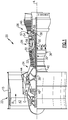
- FIG. 1 schematically illustrates a gas turbine engine 20.
- the gas turbine engine 20 is disclosed herein as a two-spool turbofan that generally incorporates a fan section 22, a compressor section 24, a combustor section 26 and a turbine section 28.
- Alternative engines might include an augmentor section (not shown) among other systems or features.
- the fan section 22 drives air along a bypass flow path B in a bypass duct defined within a nacelle 15, while the compressor section 24 drives air along a core flow path C for compression and communication into the combustor section 26 then expansion through the turbine section 28.
- the exemplary engine 20 generally includes a low speed spool 30 and a high speed spool 32 mounted for rotation about an engine central longitudinal axis A relative to an engine static structure 36 via several bearing systems 38. It should be understood that various bearing systems 38 at various locations may alternatively or additionally be provided, and the location of bearing systems 38 may be varied as appropriate to the application.
- the low speed spool 30 generally includes an inner shaft 40 that interconnects a fan 42, a first (or low) pressure compressor 44 and a first (or low) pressure turbine 46.
- the inner shaft 40 is connected to the fan 42 through a speed change mechanism, which in exemplary gas turbine engine 20 is illustrated as a geared architecture 48 to drive the fan 42 at a lower speed than the low speed spool 30.
- the high speed spool 32 includes an outer shaft 50 that interconnects a second (or high) pressure compressor 52 and a second (or high) pressure turbine 54.
- a combustor 56 is arranged in exemplary gas turbine 20 between the high pressure compressor 52 and the high pressure turbine 54.
- a mid-turbine frame 57 of the engine static structure 36 is arranged generally between the high pressure turbine 54 and the low pressure turbine 46.
- the mid-turbine frame 57 further supports bearing systems 38 in the turbine section 28.
- the inner shaft 40 and the outer shaft 50 are concentric and rotate via bearing systems 38 about the engine central longitudinal axis A which is collinear with their longitudinal axes.
- the core airflow is compressed by the low pressure compressor 44 then the high pressure compressor 52, mixed and burned with fuel in the combustor 56, then expanded over the high pressure turbine 54 and low pressure turbine 46.
- the mid-turbine frame 57 includes airfoils 59 which are in the core airflow path C.
- the turbines 46, 54 rotationally drive the respective low speed spool 30 and high speed spool 32 in response to the expansion.
- gear system 48 may be located aft of combustor section 26 or even aft of turbine section 28, and fan section 22 may be positioned forward or aft of the location of gear system 48.
- the engine 20 in one example is a high-bypass geared aircraft engine.
- the engine 20 bypass ratio is greater than about six, with an example embodiment being greater than about ten
- the geared architecture 48 is an epicyclic gear train, such as a planetary gear system or other gear system, with a gear reduction ratio of greater than about 2.3 and the low pressure turbine 46 has a pressure ratio that is greater than about five.
- the engine 20 bypass ratio is greater than about ten
- the fan diameter is significantly larger than that of the low pressure compressor 44
- the low pressure turbine 46 has a pressure ratio that is greater than about five.
- Low pressure turbine 46 pressure ratio is pressure measured prior to inlet of low pressure turbine 46 as related to the pressure at the outlet of the low pressure turbine 46 prior to an exhaust nozzle.
- the geared architecture 48 may be an epicycle gear train, such as a planetary gear system or other gear system, with a gear reduction ratio of greater than about 2.3:1. It should be understood, however, that the above parameters are only exemplary of one embodiment of a geared architecture engine and that the present invention is applicable to other gas turbine engines including direct drive turbofans.
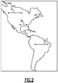
- Applicant has recognized that there may be greater challenges and stresses on aircraft engine components for the longer flights A and C than for the shorter flight B. This is because the aircraft typically carries greater weight and fuel. Thus, such flights use an engine that develops a good deal more thrust. The greater thrust provides a different amount of stresses to aircraft engine components than would be the case for the flight B. Of course, these are examples only. A flight between continents could provide different stress.
- substantially the same gas turbine engine component such as a turbine rotor with disks, blades and sideplates might be for use on gas turbine engines having a thrust rating at sea level take-off which is plus or minus 25%.
- substantially the same also means for a turbine blade, for example, the part has the substantially the same weight and substantially the same outer dimensions such that the part, without further criteria, would be interchangeable in the engine assembly. Changes to the engine control for essentially the same engine can be utilized to achieve different thrust ratings across such a range.
- flight C in a relatively hot area may result in more challenges and stresses on aircraft engine components than would the flight A or B in relatively cooler areas.
- temperatures within the gas turbine engine vary by multiples of degrees for each increased degree in ambient temperature.
- the less challenging use cases will also benefit as their utilization will not be penalized by the challenging operators "extreme use.” Said another way, the operators with less challenging use applications will receive components that are well suited for those applications, and are fully suited for the quality required of the less challenging application.
- Figure 3A shows a component 100, which is a gas turbine engine turbine blade air foil.
- a component 100 which is a gas turbine engine turbine blade air foil.
- Figure 3B shows all of the measured geometric features as the same number "999.” Of course, in practice, these numbers would all vary for different engine aircraft applications.
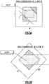
- Figure 3C shows a cross-section through the airfoil 100. Three distinct characteristics are shown. First, a central cavity 101 is spaced from an outer wall of the airfoil by a wall thickness W. Although a wall thickness W is mentioned, other aspects that would provide an indication of the shape of a cooling cavity can be utilized. Stated another way, the component may have inner cooling cavity geometric features which can be measured and the classification done, at least in part, based upon the inner geometric features. A coating has a coating thickness C.
- the airfoil 100 itself has a number of geometric characteristics shown, as one example d.
- each formed gas turbine engine component can be classified into a number of categories.
- the categories could be defined as close to specification, or spaced further from specification. Further, these differences could be quantified into a percentile ranking with gradients across the range.
- This disclosure thus classifies components on several characteristics that were never considered by the prior art. However, it then uses the classifications in a unique, and powerful way.
- a recommended use for the component can be identified.
- the temperature range for a gas turbine engine operating in a particular aircraft use is plotted against the thrust for a particular aircraft. So called “cold operator” engines might be assigned components which are further from specification whereas “hot operator” engines might receive components which are closer to specification.
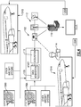
- Figure 4 shows a system 102 for utilizing this method.
- An aircraft 104 communicates with its engines 106, and data is sent to a data acquisition unit 108, and to a communication system 110 which communicates in some manner 112 such as Wi-Fi, satellite, hardwire, or other communication systems to provide information to a maintenance operator 114, or to a ground system 116.
- a communication system 110 which communicates in some manner 112 such as Wi-Fi, satellite, hardwire, or other communication systems to provide information to a maintenance operator 114, or to a ground system 116.
- FIG 4 two aircraft 104A and 104B having engines 106A and 106B, respectively, are illustrated.
- Engine 104A operates in more challenging uses, and should use “hot operator” components
- engine 104B operates in a less challenging use, and can utilize "cold operator' components.
- hot operator component 120A are being shipped for use with aircraft 104A
- cold operator” components 120B are being shipped for use with aircraft 104B.
- the same method can be used on original equipment for the aircraft, should their eventual uses be known beforehand.
- Figure 5B shows that with the disclosed method, the acceptance region can be greatly expanded as a tolerance range for a component that will necessarily be utilized on a less challenging application might be greater than for a component that might well be utilized on a very challenging application.
Landscapes
- Business, Economics & Management (AREA)
- Engineering & Computer Science (AREA)
- Human Resources & Organizations (AREA)
- Physics & Mathematics (AREA)
- General Physics & Mathematics (AREA)
- Economics (AREA)
- Strategic Management (AREA)
- Theoretical Computer Science (AREA)
- Marketing (AREA)
- Entrepreneurship & Innovation (AREA)
- General Business, Economics & Management (AREA)
- Tourism & Hospitality (AREA)
- Development Economics (AREA)
- Operations Research (AREA)
- Quality & Reliability (AREA)
- Geometry (AREA)
- Aviation & Aerospace Engineering (AREA)
- Health & Medical Sciences (AREA)
- Educational Administration (AREA)
- Finance (AREA)
- General Health & Medical Sciences (AREA)
- Accounting & Taxation (AREA)
- Game Theory and Decision Science (AREA)
- Primary Health Care (AREA)
- Manufacturing & Machinery (AREA)
- Chemical & Material Sciences (AREA)
- Combustion & Propulsion (AREA)
- Evolutionary Computation (AREA)
- Computer Hardware Design (AREA)
- Mathematical Analysis (AREA)
- General Engineering & Computer Science (AREA)
- Computational Mathematics (AREA)
- Automation & Control Theory (AREA)
- Mathematical Optimization (AREA)
- Pure & Applied Mathematics (AREA)
- Control Of Turbines (AREA)
- Turbine Rotor Nozzle Sealing (AREA)
- Management, Administration, Business Operations System, And Electronic Commerce (AREA)
- Structures Of Non-Positive Displacement Pumps (AREA)
Abstract
Description
- This application relates to a method and system for providing more effective classification of, and usage decisions on, gas turbine engine components.
- Gas turbine engines are known and typically include a fan delivering air into a compressor, where it is compressed, and then delivered into a combustor. The air is mixed with fuel and ignited. Products of this combustion pass downstream over turbine rotors, driving them to rotate. The turbine rotors, in turn, rotate the compressor and fan rotors.
- As with any manufactured components, gas turbine engine components are subject to manufacturing tolerances. As such, some components may be closer to specification, and other components may be further away. Presently, the components are closely monitored to ensure they are within acceptable tolerance range, but other than this, no actual decision is made as to an eventual use based upon the distance from specification. Thus, when components, say turbine blades, are shipped with a turbine rotor, there may be a number of turbine blades close to specification, and a number of turbine blades away from specification on a common rotor. Such a "striped" rotor has a limited operational life, as the failure of the blade spaced furthest from specification will cause the entire rotor to come offline.
- Each flight includes a speed increase at takeoff, which rapidly applies stresses on the rotating parts. Then, there is climb which is also relatively high power, cruise at altitude which is relatively low power, and then landing and a thrust reverse to stop movement of the aircraft.
- However, all flights are not equal. The stresses and challenges on the components are different for different flights.
- In a featured embodiment, a method of determining a use for substantially the same gas turbine engine components and comprises the steps of receiving manufacturing information about a plurality of gas turbine engine components; classifying each of the plurality of gas turbine engine components into at least two categories, with a first category being components closer to a specification than a second category; and recommending a suggested future use for the first category on aircraft that will operate in more challenging flight conditions and for the second category on aircraft that will operate in less challenging flight conditions.
- In another embodiment according to the previous embodiment, the recommended future use includes a suggestion to utilize component of the first and second categories on particular type flights.
- In another embodiment according to any of the previous embodiments, the particular type flights are on an engine having a particle thrust rating.
- In another embodiment according to any of the previous embodiments, the thrust ratings of all the engines at sea level take-off are plus or minus 25%.
- In another embodiment according to any of the previous embodiments, the particular type flights are for use on an aircraft flying routes having distinctly different ambient temperature.
- In another embodiment according to any of the previous embodiments, the component includes an internal cooling cavity, and the classification is done, at least in part, based upon a shape of the internal cooling cavity.
- In another embodiment according to any of the previous embodiments, the component has an outer coating, and the classification is done, at least in part, based upon on a thickness of the coating.
- In another embodiment according to any of the previous embodiments, the component has outer geometric features which are measured, and the classification is done, at least in part, based upon the outer geometric features.
- In another embodiment according to any of the previous embodiments, the component includes a cooling cavity, and the classification is also done, at least in part, based upon a wall thickness from the internal cooling cavity to an outer wall.
- In another embodiment according to any of the previous embodiments, the component has an outer coating, and the classification is also done, at least in part, on a thickness of the coating.
- In another embodiment according to any of the previous embodiments, the component has an outer coating, and the classification is also done, at least in part, on a thickness of the coating.
- In another embodiment according to any of the previous embodiments, or the method of any of claims 1 to 9, the method may further comprise installing a component classified in the first category on the first aircraft and/or a component classified in the second category on the second aircraft.
- In another featured embodiment, a system has a ground-based system programmed to perform the following steps: receiving manufacturing information about a plurality of gas turbine engine components; classifying each of the plurality of gas turbine engine components into at least two categories, with a first category being components closer to specification than a second category; and recommending a suggested future use for the first category on aircraft that will operate in more challenging flight conditions and for the second category on aircraft that will operate in less challenging flight conditions.
- In another embodiment according to the previous embodiment, the recommended future use includes a suggestion to utilize component of the first and second categories on particular type flights.
- In another embodiment according to any of the previous embodiments, the particular type flights are on an engine having a particle thrust rating.
- In another embodiment according to any of the previous embodiments, the thrust ratings of all the engines at sea level take-off are plus or minus 25%.
- In another embodiment according to any of the previous embodiments, the particular type flights are for use on an aircraft flying routes having distinctly different ambient temperature.
- In another embodiment according to any of the previous embodiments, the component includes an internal cooling cavity, and the classification is done, at least in part, based upon a shape of the internal cooling cavity.
- In another embodiment according to any of the previous embodiments, the component has an outer coating, and the classification is done, at least in part, based upon on a thickness of the coating.
- In another embodiment according to any of the previous embodiments, the component has outer geometric features which are measured, and the classification is done, at least in part, based upon the outer geometric features.
- In another embodiment according to any of the previous embodiments, the component includes an internal cooling cavity, and the classification is also done, at least in part, based upon a shape of the internal cooling cavity.
- These and other features can be best understood from the following specification and drawings, the following of which is a brief description.
-
-
Figure 1 shows a gas turbine engine schematically. -
Figure 2 shows a number of possible flight scenarios. -
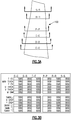
Figure 3A schematically shows an airfoil. -
Figure 3B shows data gathered with regard to a particular airfoil. -
Figure 3C shows a cross section of an airfoil. -
Figure 3D is a graph showing potential uses for particular gas turbine engine components. -
Figure 4 shows a system. -
Figure 5A shows a prior art acceptable range for a particular component. -
Figure 5B shows how the disclosed method expands the acceptable range. -
Figure 1 schematically illustrates agas turbine engine 20. Thegas turbine engine 20 is disclosed herein as a two-spool turbofan that generally incorporates afan section 22, acompressor section 24, a combustor section 26 and aturbine section 28. Alternative engines might include an augmentor section (not shown) among other systems or features. Thefan section 22 drives air along a bypass flow path B in a bypass duct defined within anacelle 15, while thecompressor section 24 drives air along a core flow path C for compression and communication into the combustor section 26 then expansion through theturbine section 28. Although depicted as a two-spool turbofan gas turbine engine in the disclosed non-limiting embodiment, it should be understood that the concepts described herein are not limited to use with two-spool turbofans as the teachings may be applied to other types of turbine engines including three-spool architectures. - The
exemplary engine 20 generally includes alow speed spool 30 and ahigh speed spool 32 mounted for rotation about an engine central longitudinal axis A relative to an enginestatic structure 36 viaseveral bearing systems 38. It should be understood thatvarious bearing systems 38 at various locations may alternatively or additionally be provided, and the location ofbearing systems 38 may be varied as appropriate to the application. - The
low speed spool 30 generally includes aninner shaft 40 that interconnects afan 42, a first (or low)pressure compressor 44 and a first (or low)pressure turbine 46. Theinner shaft 40 is connected to thefan 42 through a speed change mechanism, which in exemplarygas turbine engine 20 is illustrated as a gearedarchitecture 48 to drive thefan 42 at a lower speed than thelow speed spool 30. Thehigh speed spool 32 includes anouter shaft 50 that interconnects a second (or high)pressure compressor 52 and a second (or high)pressure turbine 54. Acombustor 56 is arranged inexemplary gas turbine 20 between thehigh pressure compressor 52 and thehigh pressure turbine 54. Amid-turbine frame 57 of the enginestatic structure 36 is arranged generally between thehigh pressure turbine 54 and thelow pressure turbine 46. Themid-turbine frame 57 further supports bearingsystems 38 in theturbine section 28. Theinner shaft 40 and theouter shaft 50 are concentric and rotate viabearing systems 38 about the engine central longitudinal axis A which is collinear with their longitudinal axes. - The core airflow is compressed by the
low pressure compressor 44 then thehigh pressure compressor 52, mixed and burned with fuel in thecombustor 56, then expanded over thehigh pressure turbine 54 andlow pressure turbine 46. Themid-turbine frame 57 includesairfoils 59 which are in the core airflow path C. Theturbines low speed spool 30 andhigh speed spool 32 in response to the expansion. It will be appreciated that each of the positions of thefan section 22,compressor section 24, combustor section 26,turbine section 28, and fandrive gear system 48 may be varied. For example,gear system 48 may be located aft of combustor section 26 or even aft ofturbine section 28, andfan section 22 may be positioned forward or aft of the location ofgear system 48. - The
engine 20 in one example is a high-bypass geared aircraft engine. In a further example, theengine 20 bypass ratio is greater than about six, with an example embodiment being greater than about ten, the gearedarchitecture 48 is an epicyclic gear train, such as a planetary gear system or other gear system, with a gear reduction ratio of greater than about 2.3 and thelow pressure turbine 46 has a pressure ratio that is greater than about five. In one disclosed embodiment, theengine 20 bypass ratio is greater than about ten, the fan diameter is significantly larger than that of thelow pressure compressor 44, and thelow pressure turbine 46 has a pressure ratio that is greater than about five.Low pressure turbine 46 pressure ratio is pressure measured prior to inlet oflow pressure turbine 46 as related to the pressure at the outlet of thelow pressure turbine 46 prior to an exhaust nozzle. The gearedarchitecture 48 may be an epicycle gear train, such as a planetary gear system or other gear system, with a gear reduction ratio of greater than about 2.3:1. It should be understood, however, that the above parameters are only exemplary of one embodiment of a geared architecture engine and that the present invention is applicable to other gas turbine engines including direct drive turbofans. - A significant amount of thrust is provided by the bypass flow B due to the high bypass ratio. The
fan section 22 of theengine 20 is designed for a particular flight condition -- typically cruise at about 0.8 Mach and about 35,000 feet (10,668 m). The flight condition of 0.8 Mach and 35,000 ft (10,668 m), with the engine at its best fuel consumption - also known as "bucket cruise Thrust Specific Fuel Consumption ('TSFC')" - is the industry standard parameter of lbm of fuel being burned divided by lbf of thrust the engine produces at that minimum point. "Low fan pressure ratio" is the pressure ratio across the fan blade alone, without a Fan Exit Guide Vane ("FEGV") system. The low fan pressure ratio as disclosed herein according to one non-limiting embodiment is less than about 1.45. "Low corrected fan tip speed" is the actual fan tip speed in ft/sec divided by an industry standard temperature correction of [(Tram °R) / (518.7 °R)]0.5 (where °R = K x 9/5). The "Low corrected fan tip speed" as disclosed herein according to one non-limiting embodiment is less than about 1150 ft / second (350.5 m/s). -
Figure 2 is a map showing the Americas. Three sample flights are illustrated. Flight A is in a cold environment and for a relatively long distance. Flight B is over a shorter distance. Flight C is over a distance which is long and in a relatively hot area closer to the equator. - Applicant has recognized that there may be greater challenges and stresses on aircraft engine components for the longer flights A and C than for the shorter flight B. This is because the aircraft typically carries greater weight and fuel. Thus, such flights use an engine that develops a good deal more thrust. The greater thrust provides a different amount of stresses to aircraft engine components than would be the case for the flight B. Of course, these are examples only. A flight between continents could provide different stress.
- In one application, substantially the same gas turbine engine component, such as a turbine rotor with disks, blades and sideplates might be for use on gas turbine engines having a thrust rating at sea level take-off which is plus or minus 25%. Substantially the same also means for a turbine blade, for example, the part has the substantially the same weight and substantially the same outer dimensions such that the part, without further criteria, would be interchangeable in the engine assembly. Changes to the engine control for essentially the same engine can be utilized to achieve different thrust ratings across such a range.
- In addition, the flight C in a relatively hot area may result in more challenges and stresses on aircraft engine components than would the flight A or B in relatively cooler areas.
- As an example, temperatures within the gas turbine engine vary by multiples of degrees for each increased degree in ambient temperature.
- In the prior art, since all gas turbine engine components are grouped together and shipped to an operator, a component which is closer to a known (or desirable) specification is as likely to be shipped with an engine to be utilized on an aircraft having more challenging conditions as to an aircraft having less challenging conditions. Similarly, a component spaced further from specification would also be as likely to be placed on an aircraft in a more challenging use as it would be to be utilized in a less challenging use.
- The teachings of this disclosure groups those gas turbine engine components closer to specification for use on more challenging applications, and such that the entire engine is provided with such components. The components which are spaced further from specification would be utilized in less challenging aircraft uses.
- Thus, a gas turbine engine utilized on a more challenging aircraft use would be operational for a longer period of time than an engine with "striped" rotor airfoil components, due to the more common components which are closer to the optimal specification of its components.
- On the other hand, an aircraft having less challenging uses would not be harmed as the components would likely be more than capable of handling the less challenging operation.
- Since useful life is often determined by the performance of the lowest capability part in the more challenging use case, the less challenging use cases will also benefit as their utilization will not be penalized by the challenging operators "extreme use." Said another way, the operators with less challenging use applications will receive components that are well suited for those applications, and are fully suited for the quality required of the less challenging application.
-
Figure 3A shows acomponent 100, which is a gas turbine engine turbine blade air foil. However, the teaching of this disclosure extends to many other components. It is known to gather a number of numeric details with regard to each formed component, as shown inFigure 3B. Figure 3B shows all of the measured geometric features as the same number "999." Of course, in practice, these numbers would all vary for different engine aircraft applications. -
Figure 3C shows a cross-section through theairfoil 100. Three distinct characteristics are shown. First, acentral cavity 101 is spaced from an outer wall of the airfoil by a wall thickness W. Although a wall thickness W is mentioned, other aspects that would provide an indication of the shape of a cooling cavity can be utilized. Stated another way, the component may have inner cooling cavity geometric features which can be measured and the classification done, at least in part, based upon the inner geometric features. A coating has a coating thickness C. Theairfoil 100 itself has a number of geometric characteristics shown, as one example d. - Among the details gathered in the table of
Figure 3B are each of the W, C and d. - By measuring and evaluating these characteristics, and other characteristics, each formed gas turbine engine component can be classified into a number of categories. The categories could be defined as close to specification, or spaced further from specification. Further, these differences could be quantified into a percentile ranking with gradients across the range.
- This disclosure thus classifies components on several characteristics that were never considered by the prior art. However, it then uses the classifications in a unique, and powerful way.
- Now, once the component has been classified into a particular category, a recommended use for the component can be identified. As an example, as shown in
Figure 3D , the temperature range for a gas turbine engine operating in a particular aircraft use is plotted against the thrust for a particular aircraft. So called "cold operator" engines might be assigned components which are further from specification whereas "hot operator" engines might receive components which are closer to specification. -
Figure 4 shows asystem 102 for utilizing this method. An aircraft 104 communicates with its engines 106, and data is sent to adata acquisition unit 108, and to acommunication system 110 which communicates in somemanner 112 such as Wi-Fi, satellite, hardwire, or other communication systems to provide information to amaintenance operator 114, or to aground system 116. Once a particular aircraft usage is known, the gas turbine engine component manufacturer can identify where the particular use is on a scale of challenging uses. - Again, those component which are likely to be capable of handling more challenging uses are assigned the components which are closer to specification, while the less challenging applications might receive components which are fully acceptable, and within tolerance range, but perhaps further from specification.
- While three characteristics are illustrated in
Figure 3C , it should be understood that the final classification into categories may occur through a combination of characteristics, or differing characteristics. The final classification algorithms can be developed over time. - In fact, in
Figure 4 , twoaircraft 104B having engines Engine 104A operates in more challenging uses, and should use "hot operator" components, whereasengine 104B operates in a less challenging use, and can utilize "cold operator' components. As shown, "hot operator"component 120A are being shipped for use withaircraft 104A, while "cold operator"components 120B are being shipped for use withaircraft 104B. Of course, the same method can be used on original equipment for the aircraft, should their eventual uses be known beforehand. -
Figure 5A shows an area of acceptance which might exist in the prior art. -
Figure 5B shows that with the disclosed method, the acceptance region can be greatly expanded as a tolerance range for a component that will necessarily be utilized on a less challenging application might be greater than for a component that might well be utilized on a very challenging application. - Although an embodiment of this invention has been disclosed, a worker of ordinary skill in this art would recognize that certain modifications would come within the scope of this invention. For that reason, the following claims should be studied to determine the true scope and content of this invention.
Claims (15)
- A method of determining a use for a plurality of gas turbine engine components comprising the steps of:measuring at least one property of said components;comparing the at least one property of each component to a known specification;classifying each component into at least first and second categories, wherein the at least one property of components in the first category is closer to said known specification than the at least one property of components in the second category; andrecommending a suggested future use for the first category on a first aircraft expected to operate in more challenging flight conditions and for the second category on a second aircraft expected to operate in less challenging flight conditions.
- The method as set forth in claim 1, wherein the recommended future use includes a suggestion to utilize components of said first and second categories on particular type flights.
- The method as set forth in claim 2, wherein the particular type flights are on an engine having a particle thrust rating.
- The method as set forth in claim 3, wherein said thrust ratings of all said engines at sea level take-off are plus or minus 25%.
- The method as set forth in claim 2, 3 or 4, wherein the particular type flights are for use on an aircraft flying routes having distinctly different ambient temperature.
- The method as set forth in any preceding claim, wherein said components include an internal cooling cavity, and said at least one property comprises a shape of said internal cooling cavity, and/or a wall thickness from said internal cooling cavity to an outer wall.
- The method as set forth in any preceding claim, wherein said components have an outer coating, and said at least one property comprises a thickness of said coating.
- The method as set forth in any preceding claim, wherein said components have outer geometric features, and said at least one property comprises said outer geometric features.
- The method as set forth in any preceding claim, further comprising manufacturing said plurality of gas turbine engine components substantially to said known specification.
- A system comprising a ground-based system programmed to perform the following steps:receiving manufacturing information about a plurality of gas turbine engine components;comprising the manufacturing information at the components to a known specification;classifying each of the components into at least two categories, with a first category being components closer to said specification than a second category;recommending a suggested future use for the first category on aircraft that will operate in more challenging flight conditions and for the second category on aircraft that will operate in less challenging flight conditions.
- The system as set forth in claim 10, wherein the recommended future use includes a suggestion to utilize component of said first and second categories on particular type flights.
- The system as set forth in claim 11, wherein:the particular type flights are on an engine having a particle thrust rating, optionally wherein said thrust ratings of all said engines at sea level take-off are plus or minus 25%; and/orthe particular type flights are for use on an aircraft flying routes having distinctly different ambient temperature.
- The system as set forth in any of claims 10 to 12, wherein said components include an internal cooling cavity, and said classification is done, at least in part, based upon a shape of said internal cooling cavity.
- The system as set forth in any of claims 10 to 13, wherein said components have an outer coating, and said classification is done, at least in part, based upon on a thickness of said coating.
- The system as set forth in any of claims 10 to 14, wherein said components have outer geometric features which are measured, and said classification is done, at least in part, based upon said outer geometric features.
Applications Claiming Priority (1)
| Application Number | Priority Date | Filing Date | Title |
|---|---|---|---|
| US15/412,293 US20180211336A1 (en) | 2017-01-23 | 2017-01-23 | Classification of Gas Turbine Engine Components and Decision for Use |
Publications (2)
| Publication Number | Publication Date |
|---|---|
| EP3352034A1 true EP3352034A1 (en) | 2018-07-25 |
| EP3352034B1 EP3352034B1 (en) | 2020-07-22 |
Family
ID=61024611
Family Applications (1)
| Application Number | Title | Priority Date | Filing Date |
|---|---|---|---|
| EP18153078.3A Active EP3352034B1 (en) | 2017-01-23 | 2018-01-23 | Classification of gas turbine engine components |
Country Status (4)
| Country | Link |
|---|---|
| US (1) | US20180211336A1 (en) |
| EP (1) | EP3352034B1 (en) |
| CN (1) | CN108345722A (en) |
| SG (1) | SG10201710673XA (en) |
Families Citing this family (4)
| Publication number | Priority date | Publication date | Assignee | Title |
|---|---|---|---|---|
| US11755791B2 (en) * | 2018-07-03 | 2023-09-12 | Rtx Corporation | Aircraft component qualification system and process |
| US11010887B2 (en) * | 2018-09-17 | 2021-05-18 | General Electric Company | Automated distress ranking system |
| GB201903646D0 (en) * | 2019-03-18 | 2019-05-01 | Rolls Royce Plc | Condition determination of a gas turbine engine |
| US20220136405A1 (en) * | 2020-10-29 | 2022-05-05 | General Electric Company | Systems and methods of servicing equipment |
Citations (3)
| Publication number | Priority date | Publication date | Assignee | Title |
|---|---|---|---|---|
| US20030167616A1 (en) * | 2002-03-08 | 2003-09-11 | General Electric Crd | Inspection and sorting system and method for part repair |
| EP2908115A1 (en) * | 2014-02-14 | 2015-08-19 | Rolls-Royce plc | Method and system for predicting the serviceable life of a component |
| EP3082004A2 (en) * | 2015-03-17 | 2016-10-19 | MTU Aero Engines GmbH | Maintenance of a used gas turbine |
Family Cites Families (18)
| Publication number | Priority date | Publication date | Assignee | Title |
|---|---|---|---|---|
| US6343251B1 (en) * | 2000-10-20 | 2002-01-29 | General Electric Company | Method and system for monitoring the operation of and predicting part life consumption for turbomachinery |
| US7021892B2 (en) * | 2003-11-19 | 2006-04-04 | Massachusetts Institute Of Technology | Method for assembling gas turbine engine components |
| US7536364B2 (en) * | 2005-04-28 | 2009-05-19 | General Electric Company | Method and system for performing model-based multi-objective asset optimization and decision-making |
| US8084086B2 (en) * | 2005-06-30 | 2011-12-27 | University Of Virginia Patent Foundation | Reliant thermal barrier coating system and related methods and apparatus of making the same |
| US20070088584A1 (en) * | 2005-10-18 | 2007-04-19 | Aragones James K | Systems and methods for managing lifecycle costs of an asset inventory |
| JP4674192B2 (en) * | 2006-09-12 | 2011-04-20 | 株式会社日立製作所 | Manufacturing product sorting method, apparatus for executing the method, and manufacturing product sorting program |
| US8532939B2 (en) * | 2008-10-31 | 2013-09-10 | General Electric Company | System and method for monitoring health of airfoils |
| US7941281B2 (en) * | 2008-12-22 | 2011-05-10 | General Electric Company | System and method for rotor blade health monitoring |
| US20110106680A1 (en) * | 2009-10-30 | 2011-05-05 | General Electric Company | Turbine operation degradation determination system and method |
| US8135568B2 (en) * | 2010-06-25 | 2012-03-13 | General Electric Company | Turbomachine airfoil life management system and method |
| US9212625B2 (en) * | 2010-11-19 | 2015-12-15 | Rudolph Allen SHELLEY | Hybrid gas turbine propulsion system |
| WO2013012568A1 (en) * | 2011-07-15 | 2013-01-24 | Irobot Corporation | Sea glider |
| US8825237B2 (en) * | 2012-04-26 | 2014-09-02 | Bell Helicopter Textron Inc. | System and method for economic usage of an aircraft |
| EP2862033B1 (en) * | 2012-06-19 | 2019-07-24 | GKN Aerospace Sweden AB | Method and system for determining life consumption of a mechanical part |
| CN103294755A (en) * | 2013-02-01 | 2013-09-11 | 税友软件集团股份有限公司 | Flexible assembling analysis method |
| US10626748B2 (en) * | 2014-12-08 | 2020-04-21 | General Electric Company | System and method for predicting and managing life consumption of gas turbine parts |
| CN106014687A (en) * | 2015-03-31 | 2016-10-12 | 黄笳唐 | Aerospace jet engine and aerospace engine taking off and landing perpendicularly |
| GB2552302B (en) * | 2016-07-11 | 2020-06-24 | Ge Aviat Systems Ltd | Prognostic rules for predicting a part failure |
-
2017
- 2017-01-23 US US15/412,293 patent/US20180211336A1/en not_active Abandoned
- 2017-12-21 SG SG10201710673XA patent/SG10201710673XA/en unknown
-
2018
- 2018-01-23 EP EP18153078.3A patent/EP3352034B1/en active Active
- 2018-01-23 CN CN201810063536.6A patent/CN108345722A/en active Pending
Patent Citations (3)
| Publication number | Priority date | Publication date | Assignee | Title |
|---|---|---|---|---|
| US20030167616A1 (en) * | 2002-03-08 | 2003-09-11 | General Electric Crd | Inspection and sorting system and method for part repair |
| EP2908115A1 (en) * | 2014-02-14 | 2015-08-19 | Rolls-Royce plc | Method and system for predicting the serviceable life of a component |
| EP3082004A2 (en) * | 2015-03-17 | 2016-10-19 | MTU Aero Engines GmbH | Maintenance of a used gas turbine |
Also Published As
| Publication number | Publication date |
|---|---|
| EP3352034B1 (en) | 2020-07-22 |
| CN108345722A (en) | 2018-07-31 |
| US20180211336A1 (en) | 2018-07-26 |
| SG10201710673XA (en) | 2018-08-30 |
Similar Documents
| Publication | Publication Date | Title |
|---|---|---|
| EP3352034B1 (en) | Classification of gas turbine engine components | |
| US10830140B2 (en) | Lubrication system for gas turbine engines | |
| EP3260656B1 (en) | Method and system for repairing an airfoil of a compressor blade of a gas turbine engine | |
| US9957832B2 (en) | Variable area turbine | |
| EP2809926B1 (en) | Variable vane scheduling based on flight conditions for inclement weather | |
| US10801359B2 (en) | Method and system for identifying rub events | |
| CN108223137B (en) | System and method for determining performance degradation of a gas turbine engine fleet | |
| EP3358144B1 (en) | Thrust rating dependent active tip clearance control system | |
| EP3483412B1 (en) | Gas turbine engine with mid-compressor bleed | |
| EP3557029B1 (en) | Intercooled cooling air fleet management system | |
| US20200070081A1 (en) | Monitoring servo-valve filter elements | |
| EP3470656B1 (en) | Modulated combustor bypass | |
| EP3647565B1 (en) | Method of controlling a gas turbine engine | |
| US10302014B2 (en) | Modifying a gas turbine engine to use a high pressure compressor as a low pressure compressor | |
| US20190211751A1 (en) | Modulated combustor bypass and combustor bypass valve | |
| US11047395B2 (en) | Fan stress tracking for turbofan gas turbine engines | |
| US10975702B2 (en) | Platform cooling arrangement for a gas turbine engine | |
| US10731477B2 (en) | Woven skin cores for turbine airfoils | |
| Silva | Turbofan Engine Behaviour Forecasting using Flight Data and Machine Learning Methods | |
| US20190338643A1 (en) | Method for manufacturing a component | |
| Kurzke et al. | Engines |
Legal Events
| Date | Code | Title | Description |
|---|---|---|---|
| PUAI | Public reference made under article 153(3) epc to a published international application that has entered the european phase |
Free format text: ORIGINAL CODE: 0009012 |
|
| STAA | Information on the status of an ep patent application or granted ep patent |
Free format text: STATUS: THE APPLICATION HAS BEEN PUBLISHED |
|
| AK | Designated contracting states |
Kind code of ref document: A1 Designated state(s): AL AT BE BG CH CY CZ DE DK EE ES FI FR GB GR HR HU IE IS IT LI LT LU LV MC MK MT NL NO PL PT RO RS SE SI SK SM TR |
|
| AX | Request for extension of the european patent |
Extension state: BA ME |
|
| STAA | Information on the status of an ep patent application or granted ep patent |
Free format text: STATUS: REQUEST FOR EXAMINATION WAS MADE |
|
| 17P | Request for examination filed |
Effective date: 20190124 |
|
| RBV | Designated contracting states (corrected) |
Designated state(s): AL AT BE BG CH CY CZ DE DK EE ES FI FR GB GR HR HU IE IS IT LI LT LU LV MC MK MT NL NO PL PT RO RS SE SI SK SM TR |
|
| RIC1 | Information provided on ipc code assigned before grant |
Ipc: G06Q 10/08 20120101ALI20190607BHEP Ipc: G01M 5/00 20060101ALI20190607BHEP Ipc: G06Q 50/04 20120101ALI20190607BHEP Ipc: G05B 23/02 20060101AFI20190607BHEP Ipc: G01M 15/14 20060101ALI20190607BHEP Ipc: G06Q 10/06 20120101ALI20190607BHEP |
|
| GRAP | Despatch of communication of intention to grant a patent |
Free format text: ORIGINAL CODE: EPIDOSNIGR1 |
|
| STAA | Information on the status of an ep patent application or granted ep patent |
Free format text: STATUS: GRANT OF PATENT IS INTENDED |
|
| INTG | Intention to grant announced |
Effective date: 20190829 |
|
| GRAJ | Information related to disapproval of communication of intention to grant by the applicant or resumption of examination proceedings by the epo deleted |
Free format text: ORIGINAL CODE: EPIDOSDIGR1 |
|
| STAA | Information on the status of an ep patent application or granted ep patent |
Free format text: STATUS: REQUEST FOR EXAMINATION WAS MADE |
|
| GRAP | Despatch of communication of intention to grant a patent |
Free format text: ORIGINAL CODE: EPIDOSNIGR1 |
|
| STAA | Information on the status of an ep patent application or granted ep patent |
Free format text: STATUS: GRANT OF PATENT IS INTENDED |
|
| INTC | Intention to grant announced (deleted) | ||
| INTG | Intention to grant announced |
Effective date: 20200205 |
|
| GRAS | Grant fee paid |
Free format text: ORIGINAL CODE: EPIDOSNIGR3 |
|
| GRAA | (expected) grant |
Free format text: ORIGINAL CODE: 0009210 |
|
| STAA | Information on the status of an ep patent application or granted ep patent |
Free format text: STATUS: THE PATENT HAS BEEN GRANTED |
|
| AK | Designated contracting states |
Kind code of ref document: B1 Designated state(s): AL AT BE BG CH CY CZ DE DK EE ES FI FR GB GR HR HU IE IS IT LI LT LU LV MC MK MT NL NO PL PT RO RS SE SI SK SM TR |
|
| REG | Reference to a national code |
Ref country code: GB Ref legal event code: FG4D |
|
| REG | Reference to a national code |
Ref country code: CH Ref legal event code: EP |
|
| REG | Reference to a national code |
Ref country code: DE Ref legal event code: R096 Ref document number: 602018006140 Country of ref document: DE |
|
| REG | Reference to a national code |
Ref country code: AT Ref legal event code: REF Ref document number: 1293998 Country of ref document: AT Kind code of ref document: T Effective date: 20200815 |
|
| REG | Reference to a national code |
Ref country code: IE Ref legal event code: FG4D |
|
| REG | Reference to a national code |
Ref country code: LT Ref legal event code: MG4D |
|
| REG | Reference to a national code |
Ref country code: AT Ref legal event code: MK05 Ref document number: 1293998 Country of ref document: AT Kind code of ref document: T Effective date: 20200722 |
|
| PG25 | Lapsed in a contracting state [announced via postgrant information from national office to epo] |
Ref country code: AT Free format text: LAPSE BECAUSE OF FAILURE TO SUBMIT A TRANSLATION OF THE DESCRIPTION OR TO PAY THE FEE WITHIN THE PRESCRIBED TIME-LIMIT Effective date: 20200722 Ref country code: BG Free format text: LAPSE BECAUSE OF FAILURE TO SUBMIT A TRANSLATION OF THE DESCRIPTION OR TO PAY THE FEE WITHIN THE PRESCRIBED TIME-LIMIT Effective date: 20201022 Ref country code: NO Free format text: LAPSE BECAUSE OF FAILURE TO SUBMIT A TRANSLATION OF THE DESCRIPTION OR TO PAY THE FEE WITHIN THE PRESCRIBED TIME-LIMIT Effective date: 20201022 Ref country code: ES Free format text: LAPSE BECAUSE OF FAILURE TO SUBMIT A TRANSLATION OF THE DESCRIPTION OR TO PAY THE FEE WITHIN THE PRESCRIBED TIME-LIMIT Effective date: 20200722 Ref country code: SE Free format text: LAPSE BECAUSE OF FAILURE TO SUBMIT A TRANSLATION OF THE DESCRIPTION OR TO PAY THE FEE WITHIN THE PRESCRIBED TIME-LIMIT Effective date: 20200722 Ref country code: FI Free format text: LAPSE BECAUSE OF FAILURE TO SUBMIT A TRANSLATION OF THE DESCRIPTION OR TO PAY THE FEE WITHIN THE PRESCRIBED TIME-LIMIT Effective date: 20200722 Ref country code: GR Free format text: LAPSE BECAUSE OF FAILURE TO SUBMIT A TRANSLATION OF THE DESCRIPTION OR TO PAY THE FEE WITHIN THE PRESCRIBED TIME-LIMIT Effective date: 20201023 Ref country code: LT Free format text: LAPSE BECAUSE OF FAILURE TO SUBMIT A TRANSLATION OF THE DESCRIPTION OR TO PAY THE FEE WITHIN THE PRESCRIBED TIME-LIMIT Effective date: 20200722 Ref country code: PT Free format text: LAPSE BECAUSE OF FAILURE TO SUBMIT A TRANSLATION OF THE DESCRIPTION OR TO PAY THE FEE WITHIN THE PRESCRIBED TIME-LIMIT Effective date: 20201123 Ref country code: HR Free format text: LAPSE BECAUSE OF FAILURE TO SUBMIT A TRANSLATION OF THE DESCRIPTION OR TO PAY THE FEE WITHIN THE PRESCRIBED TIME-LIMIT Effective date: 20200722 |
|
| PG25 | Lapsed in a contracting state [announced via postgrant information from national office to epo] |
Ref country code: IS Free format text: LAPSE BECAUSE OF FAILURE TO SUBMIT A TRANSLATION OF THE DESCRIPTION OR TO PAY THE FEE WITHIN THE PRESCRIBED TIME-LIMIT Effective date: 20201122 Ref country code: PL Free format text: LAPSE BECAUSE OF FAILURE TO SUBMIT A TRANSLATION OF THE DESCRIPTION OR TO PAY THE FEE WITHIN THE PRESCRIBED TIME-LIMIT Effective date: 20200722 Ref country code: RS Free format text: LAPSE BECAUSE OF FAILURE TO SUBMIT A TRANSLATION OF THE DESCRIPTION OR TO PAY THE FEE WITHIN THE PRESCRIBED TIME-LIMIT Effective date: 20200722 Ref country code: LV Free format text: LAPSE BECAUSE OF FAILURE TO SUBMIT A TRANSLATION OF THE DESCRIPTION OR TO PAY THE FEE WITHIN THE PRESCRIBED TIME-LIMIT Effective date: 20200722 |
|
| RAP2 | Party data changed (patent owner data changed or rights of a patent transferred) |
Owner name: RAYTHEON TECHNOLOGIES CORPORATION |
|
| PG25 | Lapsed in a contracting state [announced via postgrant information from national office to epo] |
Ref country code: NL Free format text: LAPSE BECAUSE OF FAILURE TO SUBMIT A TRANSLATION OF THE DESCRIPTION OR TO PAY THE FEE WITHIN THE PRESCRIBED TIME-LIMIT Effective date: 20200722 |
|
| REG | Reference to a national code |
Ref country code: DE Ref legal event code: R097 Ref document number: 602018006140 Country of ref document: DE |
|
| PG25 | Lapsed in a contracting state [announced via postgrant information from national office to epo] |
Ref country code: IT Free format text: LAPSE BECAUSE OF FAILURE TO SUBMIT A TRANSLATION OF THE DESCRIPTION OR TO PAY THE FEE WITHIN THE PRESCRIBED TIME-LIMIT Effective date: 20200722 Ref country code: SM Free format text: LAPSE BECAUSE OF FAILURE TO SUBMIT A TRANSLATION OF THE DESCRIPTION OR TO PAY THE FEE WITHIN THE PRESCRIBED TIME-LIMIT Effective date: 20200722 Ref country code: CZ Free format text: LAPSE BECAUSE OF FAILURE TO SUBMIT A TRANSLATION OF THE DESCRIPTION OR TO PAY THE FEE WITHIN THE PRESCRIBED TIME-LIMIT Effective date: 20200722 Ref country code: DK Free format text: LAPSE BECAUSE OF FAILURE TO SUBMIT A TRANSLATION OF THE DESCRIPTION OR TO PAY THE FEE WITHIN THE PRESCRIBED TIME-LIMIT Effective date: 20200722 Ref country code: RO Free format text: LAPSE BECAUSE OF FAILURE TO SUBMIT A TRANSLATION OF THE DESCRIPTION OR TO PAY THE FEE WITHIN THE PRESCRIBED TIME-LIMIT Effective date: 20200722 Ref country code: EE Free format text: LAPSE BECAUSE OF FAILURE TO SUBMIT A TRANSLATION OF THE DESCRIPTION OR TO PAY THE FEE WITHIN THE PRESCRIBED TIME-LIMIT Effective date: 20200722 |
|
| PLBE | No opposition filed within time limit |
Free format text: ORIGINAL CODE: 0009261 |
|
| STAA | Information on the status of an ep patent application or granted ep patent |
Free format text: STATUS: NO OPPOSITION FILED WITHIN TIME LIMIT |
|
| PG25 | Lapsed in a contracting state [announced via postgrant information from national office to epo] |
Ref country code: AL Free format text: LAPSE BECAUSE OF FAILURE TO SUBMIT A TRANSLATION OF THE DESCRIPTION OR TO PAY THE FEE WITHIN THE PRESCRIBED TIME-LIMIT Effective date: 20200722 |
|
| 26N | No opposition filed |
Effective date: 20210423 |
|
| PG25 | Lapsed in a contracting state [announced via postgrant information from national office to epo] |
Ref country code: SK Free format text: LAPSE BECAUSE OF FAILURE TO SUBMIT A TRANSLATION OF THE DESCRIPTION OR TO PAY THE FEE WITHIN THE PRESCRIBED TIME-LIMIT Effective date: 20200722 |
|
| PG25 | Lapsed in a contracting state [announced via postgrant information from national office to epo] |
Ref country code: MC Free format text: LAPSE BECAUSE OF FAILURE TO SUBMIT A TRANSLATION OF THE DESCRIPTION OR TO PAY THE FEE WITHIN THE PRESCRIBED TIME-LIMIT Effective date: 20200722 Ref country code: SI Free format text: LAPSE BECAUSE OF FAILURE TO SUBMIT A TRANSLATION OF THE DESCRIPTION OR TO PAY THE FEE WITHIN THE PRESCRIBED TIME-LIMIT Effective date: 20200722 |
|
| REG | Reference to a national code |
Ref country code: CH Ref legal event code: PL |
|
| PG25 | Lapsed in a contracting state [announced via postgrant information from national office to epo] |
Ref country code: LU Free format text: LAPSE BECAUSE OF NON-PAYMENT OF DUE FEES Effective date: 20210123 |
|
| REG | Reference to a national code |
Ref country code: BE Ref legal event code: MM Effective date: 20210131 Ref country code: NL Ref legal event code: MP Effective date: 20200722 |
|
| PG25 | Lapsed in a contracting state [announced via postgrant information from national office to epo] |
Ref country code: CH Free format text: LAPSE BECAUSE OF NON-PAYMENT OF DUE FEES Effective date: 20210131 Ref country code: LI Free format text: LAPSE BECAUSE OF NON-PAYMENT OF DUE FEES Effective date: 20210131 |
|
| PG25 | Lapsed in a contracting state [announced via postgrant information from national office to epo] |
Ref country code: IE Free format text: LAPSE BECAUSE OF NON-PAYMENT OF DUE FEES Effective date: 20210123 |
|
| PG25 | Lapsed in a contracting state [announced via postgrant information from national office to epo] |
Ref country code: BE Free format text: LAPSE BECAUSE OF NON-PAYMENT OF DUE FEES Effective date: 20210131 |
|
| P01 | Opt-out of the competence of the unified patent court (upc) registered |
Effective date: 20230520 |
|
| PG25 | Lapsed in a contracting state [announced via postgrant information from national office to epo] |
Ref country code: CY Free format text: LAPSE BECAUSE OF FAILURE TO SUBMIT A TRANSLATION OF THE DESCRIPTION OR TO PAY THE FEE WITHIN THE PRESCRIBED TIME-LIMIT Effective date: 20200722 |
|
| PG25 | Lapsed in a contracting state [announced via postgrant information from national office to epo] |
Ref country code: HU Free format text: LAPSE BECAUSE OF FAILURE TO SUBMIT A TRANSLATION OF THE DESCRIPTION OR TO PAY THE FEE WITHIN THE PRESCRIBED TIME-LIMIT; INVALID AB INITIO Effective date: 20180123 |
|
| PGFP | Annual fee paid to national office [announced via postgrant information from national office to epo] |
Ref country code: GB Payment date: 20231219 Year of fee payment: 7 |
|
| PGFP | Annual fee paid to national office [announced via postgrant information from national office to epo] |
Ref country code: FR Payment date: 20231219 Year of fee payment: 7 |
|
| PG25 | Lapsed in a contracting state [announced via postgrant information from national office to epo] |
Ref country code: MK Free format text: LAPSE BECAUSE OF FAILURE TO SUBMIT A TRANSLATION OF THE DESCRIPTION OR TO PAY THE FEE WITHIN THE PRESCRIBED TIME-LIMIT Effective date: 20200722 |
|
| PGFP | Annual fee paid to national office [announced via postgrant information from national office to epo] |
Ref country code: DE Payment date: 20231219 Year of fee payment: 7 |