EP2908115A1 - Method and system for predicting the serviceable life of a component - Google Patents
Method and system for predicting the serviceable life of a component Download PDFInfo
- Publication number
- EP2908115A1 EP2908115A1 EP15151772.9A EP15151772A EP2908115A1 EP 2908115 A1 EP2908115 A1 EP 2908115A1 EP 15151772 A EP15151772 A EP 15151772A EP 2908115 A1 EP2908115 A1 EP 2908115A1
- Authority
- EP
- European Patent Office
- Prior art keywords
- component
- crack
- detection component
- critical
- gas turbine
- Prior art date
- Legal status (The legal status is an assumption and is not a legal conclusion. Google has not performed a legal analysis and makes no representation as to the accuracy of the status listed.)
- Granted
Links
- 238000000034 method Methods 0.000 title claims description 28
- 238000001514 detection method Methods 0.000 claims abstract description 189
- 230000000977 initiatory effect Effects 0.000 claims description 93
- 239000000463 material Substances 0.000 claims description 29
- 230000015572 biosynthetic process Effects 0.000 claims description 27
- 230000002596 correlated effect Effects 0.000 claims description 12
- 238000007689 inspection Methods 0.000 description 13
- 238000013459 approach Methods 0.000 description 6
- 238000005242 forging Methods 0.000 description 6
- 230000002829 reductive effect Effects 0.000 description 6
- 238000004519 manufacturing process Methods 0.000 description 5
- 230000003068 static effect Effects 0.000 description 5
- 238000004458 analytical method Methods 0.000 description 4
- 238000012937 correction Methods 0.000 description 4
- 238000012360 testing method Methods 0.000 description 4
- 238000002485 combustion reaction Methods 0.000 description 3
- 238000005336 cracking Methods 0.000 description 3
- 231100001261 hazardous Toxicity 0.000 description 3
- 230000001141 propulsive effect Effects 0.000 description 3
- 230000000875 corresponding effect Effects 0.000 description 2
- 238000002474 experimental method Methods 0.000 description 2
- 238000011065 in-situ storage Methods 0.000 description 2
- 230000000670 limiting effect Effects 0.000 description 2
- 238000009659 non-destructive testing Methods 0.000 description 2
- 238000011179 visual inspection Methods 0.000 description 2
- 238000002441 X-ray diffraction Methods 0.000 description 1
- 230000006835 compression Effects 0.000 description 1
- 238000007906 compression Methods 0.000 description 1
- 230000001010 compromised effect Effects 0.000 description 1
- 238000010276 construction Methods 0.000 description 1
- 238000007796 conventional method Methods 0.000 description 1
- 125000004122 cyclic group Chemical group 0.000 description 1
- 230000007423 decrease Effects 0.000 description 1
- 230000006866 deterioration Effects 0.000 description 1
- 230000001627 detrimental effect Effects 0.000 description 1
- 238000009826 distribution Methods 0.000 description 1
- 230000004064 dysfunction Effects 0.000 description 1
- 230000003628 erosive effect Effects 0.000 description 1
- 239000000446 fuel Substances 0.000 description 1
- 230000007246 mechanism Effects 0.000 description 1
- 239000000203 mixture Substances 0.000 description 1
- 238000012986 modification Methods 0.000 description 1
- 230000004048 modification Effects 0.000 description 1
- 230000003647 oxidation Effects 0.000 description 1
- 238000007254 oxidation reaction Methods 0.000 description 1
- 238000010248 power generation Methods 0.000 description 1
- 230000002028 premature Effects 0.000 description 1
- 230000002441 reversible effect Effects 0.000 description 1
- 238000001228 spectrum Methods 0.000 description 1
- 238000013519 translation Methods 0.000 description 1
Images


Classifications
-
- G—PHYSICS
- G01—MEASURING; TESTING
- G01M—TESTING STATIC OR DYNAMIC BALANCE OF MACHINES OR STRUCTURES; TESTING OF STRUCTURES OR APPARATUS, NOT OTHERWISE PROVIDED FOR
- G01M15/00—Testing of engines
- G01M15/14—Testing gas-turbine engines or jet-propulsion engines
-
- G—PHYSICS
- G01—MEASURING; TESTING
- G01M—TESTING STATIC OR DYNAMIC BALANCE OF MACHINES OR STRUCTURES; TESTING OF STRUCTURES OR APPARATUS, NOT OTHERWISE PROVIDED FOR
- G01M5/00—Investigating the elasticity of structures, e.g. deflection of bridges or air-craft wings
- G01M5/0016—Investigating the elasticity of structures, e.g. deflection of bridges or air-craft wings of aircraft wings or blades
-
- G—PHYSICS
- G01—MEASURING; TESTING
- G01M—TESTING STATIC OR DYNAMIC BALANCE OF MACHINES OR STRUCTURES; TESTING OF STRUCTURES OR APPARATUS, NOT OTHERWISE PROVIDED FOR
- G01M5/00—Investigating the elasticity of structures, e.g. deflection of bridges or air-craft wings
- G01M5/0033—Investigating the elasticity of structures, e.g. deflection of bridges or air-craft wings by determining damage, crack or wear
Definitions
- the present disclosure relates to a method and apparatus for predicting the serviceable life of a component subjected to service loading and a system for performing such predictive analysis.
- Examples of the disclosure relate to a method and system for predicting the serviceable life of components of a gas turbine engine.
- DSCL Declared Safe Cyclic Life
- the in-service loading of aircraft gas turbine components includes a variety of stress mechanisms including complex three-dimensional stress fields, low cycle fatigue, high cycle fatigue, elasto-plastic loading, creep, oxidation and erosion.
- the levels of stress experienced by such components can vary widely across the different parts of the flight cycle, e.g. taxiing, take-off, cruise and landing.
- the stress levels may vary depending on the specific engine and/or aeroplane and/or operator.
- some routes and/or operators may operate at generally higher thrust than others, some pilots may use the engines differently, and different routes may experience different climatic conditions (for example temperature/air pressure/air density at take-off, landing or cruise).
- different operators may use the engine with different specific conditions (for example different usage of throttle movements during landing or climb, different mission length with different time exposure at elevated temperature) leading to complex loading spectra of the components. Those complex loading conditions can lead to different levels of damage within the component.
- the material properties of a component can vary with a large scatter, for example from batch to batch, leading to different lives for nominally the same components operating under the same conditions.
- the DSCL for a component part is determined on a conservative basis.
- a conservative flight profile (for example in terms of engine speed, cruise, take-off and landing conditions) is assumed, i.e. one in which the component would be subjected to relatively high damage.
- a statistical estimation is then used on the basis that the component has the worst physical (such as material) properties out of a certain number, for example the worst properties out of a sample of 1000 components. This is illustrated by way of example in Figure 1 .
- NDT non-destructive testing
- a method of predicting a remaining serviceable life of a critical rotating component of a gas turbine engine comprising:
- a gas turbine engine comprising:
- Formation of a crack at the crack initiation feature may allow an estimation to be made of the remaining serviceable life of the gas turbine engine.
- the crack-status of the detection component (i.e. whether a crack has formed therein) may be said to be correlated to the remaining serviceable life of the critical rotating component.
- a crack may form in the detection component before the end of the serviceable life of the critical rotating component.
- Failure or loss of integrity of the critical rotating component may be hazardous to the operation of the gas turbine engine and/or to an airframe to which the engine is attached. Cracking of the detection component may not be hazardous and/or critical to the operation of the gas turbine engine or an associated airframe.
- the methods and apparatus disclosed herein may allow more accurate prediction of the remaining serviceable life of a critical component of a gas turbine engine.
- the separate (or remote) detection component may be more accessible than the component whose remaining service life is being estimated. Cracking of the detection component (for example due to fatigue) may not affect the operation of the component whose remaining life is being estimated and/or may not affect the operation of any other part of gas turbine engine.
- the methods and apparatus disclosed herein for estimating the remaining serviceable life of a critical component may not have any detrimental impact on the integrity or life of the critical component itself, and may thus be considered to be entirely safe.
- a crack may form in the detection component due to fatigue, for example low cycle fatigue.
- the fatigue life of a critical component may be estimated from crack formation in the detection component.
- the methods and apparatus disclosed herein may mean that critical components remain in safe service for longer periods than would be the case if conventional techniques were used for estimating their life.
- the detection component may effectively allow a direct record of the loading/operating history of the critical component.
- the estimation of a remaining life of a component may be based on its operational life, for example, thereby allowing the life (for example remaining life) of each individual critical component to be estimated more accurately.
- the methods and apparatus of the present disclosure may allow the detection of premature damage to critical components, for example through fatigue. This may enhance the reliability and/or safety of such components.
- the detection component may be said to have a perimeter edge, and a crack may be determined to have formed at the crack-initiation feature only if the crack extends from the crack initiation feature to the perimeter edge. This may allow a straightforward, reliable and/or repeatable determination of whether a crack has formed. Additionally or alternatively, a crack may be determined to have formed if it has at least a minimum length.
- the detection component may be provided with first and second crack initiation features.
- the first and second crack initiation features may be provided at respective first and second distances from a perimeter edge of the detection component. The first distance may be less than the second distance.
- a first estimation of remaining serviceable life of the critical component may be based on crack formation at the first crack initiation feature.
- a second estimation of remaining serviceable life of the critical component may be based on crack formation at the second crack initiation feature.
- Providing more than one crack initiation feature may allow the remaining serviceable life of the critical component to be estimated with particularly high accuracy.
- the detection component may be arranged such that a first crack forms at a first crack initiation feature before a second crack forms at a second crack initiation feature. This may allow an early indication of the remaining serviceable life of the critical component (from the appearance of first crack), as well as a more accurate estimation closer to the limit of the serviceable life (from the appearance of second crack)
- the detection component may comprise a plurality of crack initiation features.
- the crack initiation features may be provided at respective distances from a perimeter edge of the detection component, for example with a least two of respective distances being different to each other. This may allow a plurality of respective estimations of remaining serviceable life of the critical component to be made based on crack formation at each of the crack initiation features.
- a predetermined estimated remaining serviceable life may mean that the remaining serviceable life is estimated to be or include a number of rotational cycles (or revolutions) of the gas turbine engine and/or a number of flight cycles, including take-off, cruise, and landing, for example.
- a correlation between the crack status of the detection component and the remaining serviceable life of the critical rotating component may be established prior to the step of inspecting the detection component.
- the correlation may be established through prior testing.
- prior testing may include, for example testing the additional use (for example in terms of engine rotational cycles and/or flight cycles) between when a crack forms in the detection component and when the critical rotating component is compromised (for example when it fails, for example through crack formation).
- the correlation between crack formation in the detection component and the remaining serviceable life of the critical rotating component may comprise consideration of at least one of:
- the geometry of the detection component may be such that the stress (which may be a non-dimensional stress, such as the stress divided by the proof stress of the component), for example the maximum stress, generated in the detection component in use is a known amount higher than that generated in the critical rotating component.
- This increased stress may be generated at the crack initiation feature.
- the increased stress may be known as an "overstress".
- This overstress may be related to a reduced life (for example reduced number of cycles of the gas turbine engine, e.g. in terms of engine rotations and/or flight cycles) through known material properties, for example.
- the remaining serviceable life of a critical rotating component may be estimated on a number of different occasions through the life of the component.
- the occasions may correspond to servicing of the gas turbine engine.
- a method of predicting a remaining serviceable life of a critical rotating component as described herein wherein the steps of inspecting the detection component and estimating a remaining serviceable life of the critical rotating component are performed at predetermined intervals.
- Such predetermined intervals may correspond to engine service intervals, for example.
- Such predetermined intervals may be based on the use of the engine, for example on the number of rotational cycles (or revolutions) of the engine and/or the number of flight cycles, including take-off, cruise and landing.
- the detection component may be constructed and arranged to remain as a single unit in the event of crack formation at one or more crack initiation features. As such, crack formation at the crack initiation feature may not result in failure of the detection component. Such failure may be defined as, for example, breaking or fracturing of the component into at least two parts.
- a crack formed in the detection component may be referred to as a non-dysfunctional crack.
- non-dysfunctional crack may be used to refer to a crack that can propagate without failure of the component.
- a crack formed in the detection component may be sufficiently small relative to the size of the detection component itself that the function and/or operation of the detection component remains substantially unaffected by the presence of a crack, for example with no unwanted imbalance or vibration.
- the detection component may be arranged such that even if it were to fail, its failure is not critical to the operation of the gas turbine engine.
- the sole purpose of the detection component may be for use in estimating the remaining serviceable life of the critical rotating component.
- Such a detection component may be referred to as a sacrificial detection component.
- the detection component may be a stationary (that is non-rotating) component of the gas turbine engine.
- a gas turbine engine according to the present disclosure may define a core flow path. Flow through the core flow path may pass through the combustor of the gas turbine engine in use.
- the detection component may be a stationary component placed in core flow path. Purely by way of example only, the detection component may be a stationary vane having a platform and an aerofoil portion. The crack-initiation feature may be provided on the platform.
- the stationary vane may be a nozzle guide vane, for example a guide vane that is immediately downstream of the combustor.
- crack formation in a static detection component may be correlated to the life of a rotating component.
- the stress that it experiences in use, and thus its crack status at a given time may in general be correlated to the pressures and temperatures that it experiences during use.
- the stress experienced by a rotating component, and thus its remaining life at a given time may be a function of the rotational speed, as well as the pressures and temperatures that it experiences.
- pressure and temperature are generally a function of the rotational speed of the engine (higher shaft speeds generally corresponding to higher temperatures and pressures).
- the stress history of a static component in a gas turbine engine (for example one that is in the gas-flow path) is highly correlated to the stress history of a rotating component in the same gas turbine engine.
- Such stress histories may include, for example, high stress at take off, which reduces during the climb phase of a flight, is static during cruise, and then has high stress spikes during landing, for example during a thrust reverse cycle.
- the detection component may itself be a rotating component.
- the detection component may rotate at the same speed as the critical rotating component.
- the detection component and the critical rotating component may be part of or may be connected to the same shaft of a gas turbine engine.
- the detection component and the critical rotating component may rotate at different speeds, for example by being connected to different shafts.
- a rotating detection component may or may not be provided in a gas flow path (for example a core gas flow path) of the gas turbine engine.
- the detection component may be a rotating blade having a platform and an aerofoil portion.
- the crack initiation feature may be provided on the platform.
- the detection component may be a disc connected to a rotating shaft of the gas turbine engine.
- a disc may be a dedicated detection component, whose sole function is for use in estimating the life of a critical component, for example by providing one or more crack initiation features.
- Such a disc may be located in the engine in a position that has substantially no impact on gas flow through the engine.
- Such a disc (which may be referred to as a detection disc, or a mini-disc) may be placed in a location that is not in the gas flow path of the engine.
- the detection component and the critical rotating component may be manufactured using the same material, and optionally using the same forging.
- the detection component and the critical rotating component may be manufactured as different component parts of a single forging, for example.
- the reduced life of the detection component may then be determined from the overstress simply through known material properties.
- the detection component and the critical component may be manufactured using the same material, but from a different forging and/or different method of manufacture.
- a correction factor which may be or include a safety factor, may be applied when calculating the reduced life of the detection component from the overstress to account for the different method of manufacture and/or (possibly unknown) variations in the different forgings.
- the detection component may be manufactured from a different material to the critical rotating component.
- a correction factor which may be or include a safety factor, may be applied when calculating the reduced life of the detection component from the overstress to account for the different material properties.
- a correlation between crack formation in the detection component and the remaining serviceable life of the critical rotating component may be stored on a computer readable medium and/or the estimation of the remaining serviceable life may be performed on a computer.
- More than one detection component may be provided to a gas turbine engine. More than one detection component may be inspected according to methods of the present disclosure. More than one detection component may be used to predict the remaining serviceable life of a single critical rotating part. This may provide a particularly accurate estimate of the remaining serviceable life of the critical rotating part.
- the critical rotating component may be any suitable component for which an estimation of the remaining service life is desired.
- the critical rotating component may be a rotating shaft (for example a rotating compressor and/or turbine shaft), or a turbine or compressor disc.
- a rotating disc may carry rotating blades of the gas turbine engine.
- Such blades may be integral to the disc (for example in the form of a bladed disk (“blisk”) or bladed ring ("bling”), or may be separate component that are attached to the disc via root portions.
- the crack initiation feature may provide a site at which a crack forms in the detection component after a repeatable stress exposure (or stress history) of the detection component.
- the crack initiation feature may be a hole, a notch, a groove, a boss, or a flange or a slot, such as a slot that is provided in standard specimens for measuring crack formation/propagation.
- the crack initiation feature may extend entirely through the detection component. Alternatively, the crack initiation feature may not extend entirely through the detection component. Where the crack initiation feature is provided in a component that may be in a gas flow path, providing a crack initiation feature that does not extend entirely through the detection component may help to reduce, or substantially eliminate any impact on the gas flow.
- Inspecting a detection component may comprise performing a visual inspection.
- the detection component may be visually inspected to determine whether a crack has formed.
- the inspection of the detection component may be undertaken by any convenient inspection method. This may include ultrasonic, x-ray analysis, fluoro-penetrant dye inspection and/or boroscope inspection.
- the detection component may be accessible (for example for inspection) in-situ, for example without the need to dismantle the gas turbine engine.
- the detection component may be said to be more accessible than the critical component whose remaining serviceable life is being estimated. This may mean that access (for example for inspection) to the detection component is easier and/or less time consuming than access to the component whose remaining serviceable life is being estimated.
- Access to the detection component may be through a boroscope hole, which may be an existing boroscope hole use for other inspection purposes in the gas turbine engine, for example.
- a gas turbine engine according to an aspect may comprise an access feature arranged to allow access to the detection component.
- Such an access feature which may be a boroscope hole, may enable inspection of the detection component in-situ, for example without the need to dismantle the engine.
- a ducted fan gas turbine engine generally indicated at 10 has a principal and rotational axis X-X.
- the engine 10 comprises, in axial flow series, an air intake 11, a propulsive fan 12, an intermediate pressure compressor 13, a high-pressure compressor 14, combustion equipment 15, a high-pressure turbine 16, and intermediate pressure turbine 17, a low-pressure turbine 18 and a core engine exhaust nozzle 19.
- the engine also has a bypass duct 22 and a bypass exhaust nozzle 23.
- the gas turbine engine 10 works in a conventional manner so that air entering the intake 11 is accelerated by the fan 12 to produce two air flows: a first air flow A into the intermediate pressure compressor 13 and a second air flow B which passes through the bypass duct 22 to provide propulsive thrust.
- the intermediate pressure compressor 13 compresses the air flow A directed into it before delivering that air to the high pressure compressor 14 where further compression takes place.
- the compressed air exhausted from the high-pressure compressor 14 is directed into the combustion equipment 15 where it is mixed with fuel and the mixture combusted.
- the resultant hot combustion products then expand through, and thereby drive the high, intermediate and low-pressure turbines 16, 17, 18 before being exhausted through the nozzle 19 to provide additional propulsive thrust.
- the high, intermediate and low-pressure turbines 16, 17, 18 respectively drive the high and intermediate pressure compressors 14, 13 and the fan 12 by suitable interconnecting shafts.
- each of the turbine stages 16, 17, 18 and each of the compressor stages 12, 13, 14 comprises aerofoil components that are attached to a rotating disc (such as the turbine discs labelled 170, 180 in Figure 2 ), and the rotating disc may be deemed to be critical to the operation of the gas turbine engine 10.
- these rotating discs are examples of critical rotating components for which accurate estimation of the remaining serviceable life is advantageous.
- the gas turbine engine 10 is provided with detection components 100, 200, 300, as shown in Figure 2 . It will be appreciated that, whilst the gas turbine engine of Figure 2 is shown as comprising three separate detection components 100, 200, 300, any one or more than one such detection components 100, 200, 300 may be provided.
- a gas turbine engine 10 may comprise a rotating detection component 100, as in the example shown in Figure 2 in which a rotating detection component 100 is fixedly attached to (for example mounted to or mounted on) a rotating shaft 30.
- the rotating detection component 100 may thus be configured to rotate at the same speed as the shaft 30 during use.
- the rotating shaft 30 may also have at least one turbine and/or compressor rotor stage mounted thereon.
- the rotating detection component 100 may be used to predict the remaining serviceable life of a component that rotates at the same speed (for example a rotating component, such as a turbine disc 170, that is attached to the same shaft 30), or at a different speed (for example a rotating component, such as a turbine disc 180, that is attached to a different rotating shaft).
- the difference in shaft rotational speeds may be well known, for example from engine performance modelling, so the detection component 100 and the critical component 170, 180 may or may not be attached to the same shaft.
- the rotating detection component 100 may itself be a disc or other feature that rotates with the shaft 30 in use. In some arrangements, the sole purpose of the rotating detection component 100 may be in predicting the remaining serviceable life of a critical rotating component 170, 180.
- a stationary detection component 200, 300 may be provided in addition to or instead of the rotating detection component 100.
- two stationary detection components 200, 300 are provided.
- One of the detection components 200 is a dedicated detection component 200.
- the sole function of the dedicated detection component 200 may be in predicting the remaining serviceable life of a critical rotating component 170, 180. Indeed, any detection component 100, 200, 300 - stationary or rotating - may be a dedicated detection component 200.
- any detection component 100, 200, 300 may perform another function in additional to its use in predicting the remaining serviceable life of another component.
- a stationary detection component may be a guide vane, such as the guide vane that forms the stationary detection component 300 in the Figure 2 example.
- a crack initiation feature (described in greater detail by way of example below) may be provided on a platform of a guide vane, such as a nozzle guide vane immediately downstream of the combustor 15.
- a stationary detection component 200, 300 would not rotate with the critical rotating component 170, 180, its service life may still correlate with the service life of a critical rotating component.
- the stress experienced by the stationary detection component 200, 300 may be mainly a function of the temperature and/or pressure to which it is exposed. But the temperatures and pressures are generally functions of shaft speed in a gas turbine engine 10. Accordingly, the stress experienced by a critical rotating component 170, 180 (which is generally a function of rotational speed, temperature and pressure) in a gas turbine engine 10 may be correlated to the stress experienced by a stationary component 200, 300.
- the stationary static components 200, 300 may be placed in the airflow A that passes through the core of the gas turbine engine (i.e. through the intermediate and high pressure compressors 13, 14, the combustor 15, and the turbines 16, 17, 18) to provide a particularly accurate correlation between its own life and that of a critical rotating component 170, 180.
- Each detection component 100, 200, 300 is provided with one or more crack initiation features 50.
- Figure 3 shows a detailed view of a part of a detection component 100, 200, 300 including an example of such a crack initiation feature 50.
- the crack initiation feature 50 is provided in the form of a hole 50 in the detection component 100, 200, 300.
- the hole 50 (or indeed any other crack initiation feature 50) may extend through the detection component 100, 200, 300, or may only extend partly into the detection component 100, 200, 300.
- the crack initiation feature 50 is located a pre-determined distance 54 from a free edge (or perimeter edge) 56 of the detection component 100, 200, 300.
- the distance 54 is determined such that the resulting stress concentration factor at the hole 50 results in the initiation of a crack 60 after a given period (for example a given number of flight and/or engine cycles) of use of the detection component 100, 200, 300.
- the crack 60 may be referred to as a non-dysfunctional crack 60, because its formation may not be critical to the operation of the detection component 100, 200, 300 (which may be particularly important where the detection component 100, 200, 300 performs an additional function in the engine, such as a vane) and/or to the operation of the gas turbine engine 10. Due to the relative construction and arrangement of the detection component 100, 200, 300 and the critical rotating component 170, 180, the non-dysfunctional crack 60 forms earlier than any meaningful deterioration (for example any uncontrolled crack formation) in the critical rotating component 170, 180.
- the desired size and positioning of the crack initiation feature 50, required to produce a given stress concentration factor for example, may be determined by any known technique, such as by experiment and/or by an analytical modelling technique (such as, for example, finite element analysis). Accordingly, the expected stress concentration at the hole 50 during use may be well known and understood. Accordingly, the appearance of a non-dysfunctional crack 60 in the detection component 100, 200, 300 may be readily correlated to the stress history of the detection component 100, 200, 300. This stress history of the detection component 100, 200, 300 may then be readily correlated to the stress history of a critical rotating component, and thus the remaining serviceable life of that critical rotating component.
- the detection component(s) 100, 200, 300 may be inspected for the appearance of a crack 60 at the crack initiation feature 50, at pre-determined intervals.
- the intervals may correspond to service intervals, which may be determined in any suitable manner, for example on the basis of the number of hours for which the gas turbine engine 10 has been in operation and/or the number of cycles of the engine.
- the inspection may take any suitable form such as, for example, a visual inspection. Purely by way of example, a boroscope may be used to perform the inspection.
- a crack 60 is detected in the detection component 100, 200, 300, then a known, for example pre-determined, correlation may be applied to estimate a remaining serviceable life of a remote, critical component 170, 180. It may be assumed, for example, that the crack 60 appeared immediately after the previous inspection. This would be a particularly cautious approach, and it will be appreciated that other approaches are possible. For example, it may be possible to estimate from the crack 60 (for example from its size, such as its length) the age of the crack (for example in terms of engine cycles), and thus when the crack 60 formed. This may allow a more accurate estimation of the remaining serviceable life of the critical component 170, 180.
- one possible approach is to determine that a crack 60 has formed at the crack initiation feature 50 if and only if the crack 60 extends from the crack initiation feature 50 to a perimeter edge 56 of the detection component 100, 200, 300, as in the Figure 3 example.
- This may provide a particularly repeatable technique for determining whether a crack 60 has formed.
- it will be appreciated that other approaches are possible, for example determining whether a crack 60 of any detectable size has formed, or determining whether a crack 60 over a certain size (for example length) has formed.
- any one or more detection components 100, 200, 300 may comprise one or more than one crack initiation feature.
- Figures 4A and 4B show a portion of a detection component 100, 200, 300 that comprises four crack initiation features 150, 152, 154, 156.
- Each of the crack initiation features 150, 152, 154, 156 may be substantially as described above in relation to the crack initiation feature 50 of Figure 3 .
- each of the crack initiation features 150, 152, 154, 156 may be a hole.
- any one or more of the crack initiation features 150, 152, 154, 156 may take a different form such as, by way of example only, a notch, a groove, a boss, a flange, or a slot, such as would be used in a standard crack test specimen, for example.
- the stress concentration may be different for each of the crack initiation features 150, 152, 154, 156.
- each of the plurality of crack initiation features 150, 152, 154, 156 may be positioned a successively greater distance 122, 124, 126, 128 from a perimeter edge 56 of the detection component 100, 200, 300.
- the stress concentration at each crack initiation feature 150, 152, 154, 156 may successively increase from right to left in the arrangement shown in Figures 4A and 4B , as the distance from the respective crack initiation feature 150, 152, 154, 156 to the perimeter edge 56 decreases.
- the expected stress concentration at each crack initiation feature 150, 152, 154, 156 during use may be well known and understood, for example by using a modelling technique such as finite element analysis (FEA) or by experiment.
- a non-dysfunctional crack 162, 164, 166 originating from the second and subsequent crack initiation features 152, 154, 156 would be designed to form after (for example following a greater number of engine cycles) the formation of a crack originating from a crack initiation feature 150, 152, 154 that has a higher stress concentration in use. That is, the second, third and fourth crack initiation features 152,154,156 may be sized and/or located in the component 100 such that corresponding non-dysfunctional cracks 162,164,166 are initiated following successive periods of operation of the component 100.
- non-dysfunctional crack 160 originating at a first crack initiation feature 150 in the detection component 100, 200, 300 may be readily correlated to the stress history of the detection component 100, 200, 300.
- appearance of non-dysfunctional cracks 162, 164, 166 originating at second and subsequent crack initiation features 152, 154, 156 may also be correlated to the stress history of the detection component.
- each non-dysfunctional crack the stress history of the detection component 100, 200, 300 may then be readily correlated to the stress history of a critical rotating component 170, 180, and thus the remaining serviceable life of that critical rotating component 170, 180.
- a first estimation of the remaining serviceable life may be estimated after the formation of the first non-dysfunctional crack 160
- subsequent (second, third, fourth and so on) estimations of the remaining serviceable life may be estimated after the formation of subsequent non-dysfunctional cracks from the crack initiation features 152, 154, 156 having successively lower stress concentrations.
- the detection component may be arranged such that once a crack 166 is detected at the crack initiation feature 156 having the lowest stress concentration, the critical rotating component 170, 180 may be estimated to have no remaining serviceable life.
- the crack initiation feature 156 with the lowest stress concentration may be a fail-safe feature which indicates that a critical component may need to be replaced immediately.
- the detection component 100, 200, 300 may be either rotating or stationary, and may be provided at any convenient position/location and in any desired manner.
- the position of the detection component may be chosen based on, for example, ease of access for inspection and/or accuracy of correlation between its own life (for example as determined by crack formation) and that of the critical component 170, 180.
- the detection component 100, 200, 300 may be positioned a considerable distance from the critical rotating component 170, 180 whose life is being estimated, and the relationships discussed herein by way of example may be used in order to correlate crack formation in the detection component 100, 200, 300 with the remaining serviceable life of the critical rotating component.
- Figure 5 is an illustrative example of the correlation between the life (which may be any suitable measure, such as number of cycles) of a detection component 100, 200, 300 and that of a critical component 170, 180.
- the life of the detection component 100, 200, 300 may be determined as being the point at which a crack 60 appears from a respective crack initiation feature 50 and thus may or may not represent the actual serviceable life of the detection component 100, 200, 300. It will be appreciated that the explanation given below in relation to Figure 5 is purely by way of an example of how the life of the two components may be related, and that other explanations may be used.
- the overstress ⁇ in Figure 5 represents the additional stress experienced by the detection component 100, 200, 300 (for example at a crack initiation feature 50) over that experienced by the critical component 170, 180 in use. This may be known through, for example, experimentation and/or analysis (such as FEA).
- the same material for example same base material and same manufacturing process
- known material properties may be used to correlate the life of the detection component 100, 200, 300 and the life of the critical component 170, 180.
- the relationship between stress and life may take any form, depending on the material. For example, for one material, the relationship may be a straight line between the points A (representing life of the detection component 100, 200, 300) and B (representing the estimated life of the lower-stressed critical component 170, 180) in Figure 5 . For a different material the relationship may be a curve, as shown in Figure 5 between the points A and B'.
- empirical and/or experimental data may be used to generate the relationship between the stress and life for a given material.
- a different material may be used for the detection component 100, 200, 300 to that which is used for the critical component 170, 180.
- different material may mean different material properties, and so may include the use of a different base material and/or the use of a different manufacturing process (for example a different forging process where both components are forged).
- a correction may be used to account for the different material properties.
- a correction may be used to take the estimated life of the critical component 170, 180 from the point B (at which it would be given the same material properties) to the point C.
- the translation from point B in Figure 5 to point C may be in either direction (i.e. longer or shorter life), depending on the relative material properties.
- the estimated life at point C of the critical component 170, 180 may be established directly from point A (the life of the detection component 100, 200, 300) using relative material properties, which may be known, for example, through empirical and/or experimental data.
- a safety margin may be applied. This may effectively shift the estimated life of the critical component 170, 180 to the left in figure 5 , from point B towards (or to) point C.
- a safety margin may be included when estimating the life of the critical component 170, 180 from that of the detection component 100, 200, 300, thereby effectively shifting the points B and C in Figure 5 to the left.
- Using a greater number of detection components 100, 200, 300 and/or crack initiation features 50, 150, 152, 154, 156 may help to increase the confidence in the estimated life of the critical component 170, 180, and may thus allow any safety margin to be reduced.
- Figure 6 is a more detailed schematic view of a detection component 100, which may represent, for example, the rotating detection component 100 shown in Figure 2 .
- the features shown in Figure 6 that correspond to features described in relation to other figures are given like reference numerals.
- the detection component 100 may be a rotational component that rotates about an axis X-X, which may correspond to the axis X-X of a gas turbine engine 10.
- the detection component 100 may have an annular shape when viewed along its rotational axis X-X, and may be referred to as a disc, a detection disc, or a mini-disc.
- the mass (and/or rotational moment of inertia) of the disc 100 may be less than that of the critical rotating component 170, 180 whose remaining serviceable life it is being used to estimate.
- the mass (and/or rotational moment of inertia) of the disc 100 may be sufficiently low that if it were to fail (for example break apart), then it would be contained within the engine.
- a detection disc 100 may be classified as a non-critical part.
- the detection component 100 may be attached to a rotating shaft 30 of the gas turbine engine 10 using, for example, a mechanical fixing 32, as in the Figure 6 example.
- the detection component 100 is shown as having a crack initiation feature 50 near to its outer radial surface 56, which may be an example of a perimeter surface 56 as referred to elsewhere herein. However, it will be appreciated that one or more crack initiation features 50 could be provided in additional or alternative locations on the detection component 100. For example, a plurality of crack initiation features 50 may be provided at different angular positions around the detection component 100. As described elsewhere herein, each crack initiation feature 50 may be provided at different distances from the perimeter edge 56 to other crack initiation features 50.
- any critical component in any engine for example a turbofan, turbojet, turbo-prop or open-rotor gas turbine engine.
- a gas turbine engine may be for any use, for example for aircraft propulsion, industrial power generation, or marine use.
- the foregoing description of various aspects of the invention has been presented for purposes of illustration and description. It is not intended to be exhaustive or to limit the invention to the precise form disclosed. Various modifications and variations that may be apparent to a person of skill in the art are included within the scope of the invention as defined by the accompanying claims. Purely by way of non-limitative example, such variations may include the form and arrangement of detection components and/or crack initiation features.
Abstract
Description
- The present disclosure relates to a method and apparatus for predicting the serviceable life of a component subjected to service loading and a system for performing such predictive analysis. Examples of the disclosure relate to a method and system for predicting the serviceable life of components of a gas turbine engine.
- Critical component parts for aircraft gas turbine engines, whose failure could hazard the operation of the engine and/or the airframe to which it is attached, are monitored at regular intervals and are generally replaced when they reach a fixed service life to avoid any failure or dysfunction in service. This life limit is termed the Declared Safe Cyclic Life (DSCL). This replacement is undertaken irrespective of the serviceability of the component part when it reaches the DSCL.
- The in-service loading of aircraft gas turbine components includes a variety of stress mechanisms including complex three-dimensional stress fields, low cycle fatigue, high cycle fatigue, elasto-plastic loading, creep, oxidation and erosion.
- The levels of stress experienced by such components can vary widely across the different parts of the flight cycle, e.g. taxiing, take-off, cruise and landing. Furthermore, the stress levels may vary depending on the specific engine and/or aeroplane and/or operator. For example, some routes and/or operators may operate at generally higher thrust than others, some pilots may use the engines differently, and different routes may experience different climatic conditions (for example temperature/air pressure/air density at take-off, landing or cruise). By way of further example, different operators may use the engine with different specific conditions (for example different usage of throttle movements during landing or climb, different mission length with different time exposure at elevated temperature) leading to complex loading spectra of the components. Those complex loading conditions can lead to different levels of damage within the component.
- In addition to the various operational factors listed above, the material properties of a component (such as ultimate strength, proof strength, fatigue and creep strength) can vary with a large scatter, for example from batch to batch, leading to different lives for nominally the same components operating under the same conditions.
- Due to these various operational and/or component factors, such as those listed above, it is difficult to predict a serviceable life limit for individual component parts.
- As a result, the DSCL for a component part is determined on a conservative basis. A conservative flight profile (for example in terms of engine speed, cruise, take-off and landing conditions) is assumed, i.e. one in which the component would be subjected to relatively high damage. A statistical estimation is then used on the basis that the component has the worst physical (such as material) properties out of a certain number, for example the worst properties out of a sample of 1000 components. This is illustrated by way of example in
Figure 1 . - Consequently, in the above-mentioned example, when the parts reach the DSCL, at least 999 parts from a sample of 1000 parts will be scrapped whilst being un-cracked and/or still serviceable. This approach, while ensuring that the likelihood of parts failing in-service is minimised, does result in the scrappage of a considerable quantity of parts which may have considerable remaining safe working life. This results in costly routine engine overhauls.
- It is known to routinely inspect component parts of aircraft gas turbine engines at regular intervals in order to determine whether the part is cracked or damaged. A problem with this approach is the need to employ non-destructive testing (NDT) techniques to detect the onset of cracking which could potentially lead to hazardous failure of the component. In addition, waiting until a crack has appeared in a given component may be unsuitable, because once the component is cracked, it may already be unserviceable.
- According to an aspect, there is provided a method of predicting a remaining serviceable life of a critical rotating component of a gas turbine engine comprising:
- providing a detection component in the gas turbine engine with a crack initiation feature (which may be referred to as a stress raising feature), the detection component being remote from the critical rotating component;
- inspecting the detection component to determine whether a crack has formed at the crack-initiation feature; and
- estimating a remaining serviceable life of the critical rotating component based on whether a crack has formed at the crack-initiation feature.
- According to an aspect, there is provided a gas turbine engine comprising:
- a critical rotating component that is critical to the operation of the gas turbine engine;
- a detection component that is provided with a crack initiation feature and is remote from the critical rotating component, wherein:
- the crack initiation feature is arranged such that, in use, formation of a crack at the crack initiation feature is correlated to the remaining serviceable life of the critical rotating component.
- Formation of a crack at the crack initiation feature may allow an estimation to be made of the remaining serviceable life of the gas turbine engine.
- The crack-status of the detection component (i.e. whether a crack has formed therein) may be said to be correlated to the remaining serviceable life of the critical rotating component. A crack may form in the detection component before the end of the serviceable life of the critical rotating component.
- Failure or loss of integrity of the critical rotating component may be hazardous to the operation of the gas turbine engine and/or to an airframe to which the engine is attached. Cracking of the detection component may not be hazardous and/or critical to the operation of the gas turbine engine or an associated airframe.
- The methods and apparatus disclosed herein may allow more accurate prediction of the remaining serviceable life of a critical component of a gas turbine engine. The separate (or remote) detection component may be more accessible than the component whose remaining service life is being estimated. Cracking of the detection component (for example due to fatigue) may not affect the operation of the component whose remaining life is being estimated and/or may not affect the operation of any other part of gas turbine engine. As such, the methods and apparatus disclosed herein for estimating the remaining serviceable life of a critical component may not have any detrimental impact on the integrity or life of the critical component itself, and may thus be considered to be entirely safe.
- Generally, a crack may form in the detection component due to fatigue, for example low cycle fatigue. By way of example, the fatigue life of a critical component may be estimated from crack formation in the detection component.
- The methods and apparatus disclosed herein may mean that critical components remain in safe service for longer periods than would be the case if conventional techniques were used for estimating their life. The detection component may effectively allow a direct record of the loading/operating history of the critical component. The estimation of a remaining life of a component may be based on its operational life, for example, thereby allowing the life (for example remaining life) of each individual critical component to be estimated more accurately. Additionally or alternatively, the methods and apparatus of the present disclosure may allow the detection of premature damage to critical components, for example through fatigue. This may enhance the reliability and/or safety of such components.
- The detection component may be said to have a perimeter edge, and a crack may be determined to have formed at the crack-initiation feature only if the crack extends from the crack initiation feature to the perimeter edge. This may allow a straightforward, reliable and/or repeatable determination of whether a crack has formed. Additionally or alternatively, a crack may be determined to have formed if it has at least a minimum length.
- The detection component may be provided with first and second crack initiation features. The first and second crack initiation features may be provided at respective first and second distances from a perimeter edge of the detection component. The first distance may be less than the second distance. A first estimation of remaining serviceable life of the critical component may be based on crack formation at the first crack initiation feature. A second estimation of remaining serviceable life of the critical component may be based on crack formation at the second crack initiation feature.
- Providing more than one crack initiation feature (which may be referred to as a crack initiation site) may allow the remaining serviceable life of the critical component to be estimated with particularly high accuracy. The detection component may be arranged such that a first crack forms at a first crack initiation feature before a second crack forms at a second crack initiation feature. This may allow an early indication of the remaining serviceable life of the critical component (from the appearance of first crack), as well as a more accurate estimation closer to the limit of the serviceable life (from the appearance of second crack)
- The detection component may comprise a plurality of crack initiation features. The crack initiation features may be provided at respective distances from a perimeter edge of the detection component, for example with a least two of respective distances being different to each other. This may allow a plurality of respective estimations of remaining serviceable life of the critical component to be made based on crack formation at each of the crack initiation features.
- If a crack is detected in the detection component, the estimated remaining serviceable life of the critical rotating component may then be directly known. In this regard, it may be necessary to assume that the crack appeared in the detection component immediately after a directly previous inspection of the detection component.
A predetermined estimated remaining serviceable life may mean that the remaining serviceable life is estimated to be or include a number of rotational cycles (or revolutions) of the gas turbine engine and/or a number of flight cycles, including take-off, cruise, and landing, for example. - A correlation between the crack status of the detection component and the remaining serviceable life of the critical rotating component may be established prior to the step of inspecting the detection component. For example, the correlation may be established through prior testing. Such prior testing may include, for example testing the additional use (for example in terms of engine rotational cycles and/or flight cycles) between when a crack forms in the detection component and when the critical rotating component is compromised (for example when it fails, for example through crack formation).
- Additionally or alternatively the correlation between crack formation in the detection component and the remaining serviceable life of the critical rotating component may comprise consideration of at least one of:
- the geometry of the detection component, the geometry of the or each crack initiation feature and the geometry of the critical rotating component;
- the location of the detection component and the location of the critical rotating component in the gas turbine engine; and
- the material of the detection component and the material of the critical rotating component.
- For example, the geometry of the detection component may be such that the stress (which may be a non-dimensional stress, such as the stress divided by the proof stress of the component), for example the maximum stress, generated in the detection component in use is a known amount higher than that generated in the critical rotating component. This increased stress may be generated at the crack initiation feature. The increased stress may be known as an "overstress". This overstress may be related to a reduced life (for example reduced number of cycles of the gas turbine engine, e.g. in terms of engine rotations and/or flight cycles) through known material properties, for example.
- The remaining serviceable life of a critical rotating component may be estimated on a number of different occasions through the life of the component. The occasions may correspond to servicing of the gas turbine engine. According to an aspect, there is provided a method of predicting a remaining serviceable life of a critical rotating component as described herein, wherein the steps of inspecting the detection component and estimating a remaining serviceable life of the critical rotating component are performed at predetermined intervals. Such predetermined intervals may correspond to engine service intervals, for example.
- Such predetermined intervals may be based on the use of the engine, for example on the number of rotational cycles (or revolutions) of the engine and/or the number of flight cycles, including take-off, cruise and landing.
- The detection component may be constructed and arranged to remain as a single unit in the event of crack formation at one or more crack initiation features. As such, crack formation at the crack initiation feature may not result in failure of the detection component. Such failure may be defined as, for example, breaking or fracturing of the component into at least two parts. A crack formed in the detection component may be referred to as a non-dysfunctional crack. The term "non-dysfunctional crack" may be used to refer to a crack that can propagate without failure of the component. A crack formed in the detection component may be sufficiently small relative to the size of the detection component itself that the function and/or operation of the detection component remains substantially unaffected by the presence of a crack, for example with no unwanted imbalance or vibration.
- The detection component may be arranged such that even if it were to fail, its failure is not critical to the operation of the gas turbine engine. For example, the sole purpose of the detection component may be for use in estimating the remaining serviceable life of the critical rotating component. Such a detection component may be referred to as a sacrificial detection component.
- The detection component may be a stationary (that is non-rotating) component of the gas turbine engine. A gas turbine engine according to the present disclosure may define a core flow path. Flow through the core flow path may pass through the combustor of the gas turbine engine in use. The detection component may be a stationary component placed in core flow path. Purely by way of example only, the detection component may be a stationary vane having a platform and an aerofoil portion. The crack-initiation feature may be provided on the platform. Again by way of example only, the stationary vane may be a nozzle guide vane, for example a guide vane that is immediately downstream of the combustor.
- According to such an arrangement, crack formation in a static detection component may be correlated to the life of a rotating component. For example, if the detection component is static, then the stress that it experiences in use, and thus its crack status at a given time, may in general be correlated to the pressures and temperatures that it experiences during use. The stress experienced by a rotating component, and thus its remaining life at a given time, may be a function of the rotational speed, as well as the pressures and temperatures that it experiences. However, in general in a gas turbine engine, pressure and temperature are generally a function of the rotational speed of the engine (higher shaft speeds generally corresponding to higher temperatures and pressures). Accordingly, the stress history of a static component in a gas turbine engine (for example one that is in the gas-flow path) is highly correlated to the stress history of a rotating component in the same gas turbine engine. Such stress histories may include, for example, high stress at take off, which reduces during the climb phase of a flight, is static during cruise, and then has high stress spikes during landing, for example during a thrust reverse cycle.
- Of course, the detection component may itself be a rotating component. For example, the detection component may rotate at the same speed as the critical rotating component. For example, the detection component and the critical rotating component may be part of or may be connected to the same shaft of a gas turbine engine. Alternatively, the detection component and the critical rotating component may rotate at different speeds, for example by being connected to different shafts. A rotating detection component may or may not be provided in a gas flow path (for example a core gas flow path) of the gas turbine engine.
- Purely by way of example, the detection component may be a rotating blade having a platform and an aerofoil portion. In such an arrangement, the crack initiation feature may be provided on the platform.
- By way of further example, the detection component may be a disc connected to a rotating shaft of the gas turbine engine. Such a disc may be a dedicated detection component, whose sole function is for use in estimating the life of a critical component, for example by providing one or more crack initiation features. Such a disc may be located in the engine in a position that has substantially no impact on gas flow through the engine. Such a disc (which may be referred to as a detection disc, or a mini-disc) may be placed in a location that is not in the gas flow path of the engine.
- The detection component and the critical rotating component may be manufactured using the same material, and optionally using the same forging.
- The detection component and the critical rotating component may be manufactured as different component parts of a single forging, for example. The reduced life of the detection component may then be determined from the overstress simply through known material properties.
- The detection component and the critical component may be manufactured using the same material, but from a different forging and/or different method of manufacture. In that case, a correction factor, which may be or include a safety factor, may be applied when calculating the reduced life of the detection component from the overstress to account for the different method of manufacture and/or (possibly unknown) variations in the different forgings.
- The detection component may be manufactured from a different material to the critical rotating component. In that case, a correction factor, which may be or include a safety factor, may be applied when calculating the reduced life of the detection component from the overstress to account for the different material properties.
- A correlation between crack formation in the detection component and the remaining serviceable life of the critical rotating component may be stored on a computer readable medium and/or the estimation of the remaining serviceable life may be performed on a computer.
- More than one detection component may be provided to a gas turbine engine. More than one detection component may be inspected according to methods of the present disclosure. More than one detection component may be used to predict the remaining serviceable life of a single critical rotating part. This may provide a particularly accurate estimate of the remaining serviceable life of the critical rotating part.
- Throughout the present disclosure, the critical rotating component may be any suitable component for which an estimation of the remaining service life is desired. By way of non-limitative example, the critical rotating component may be a rotating shaft (for example a rotating compressor and/or turbine shaft), or a turbine or compressor disc. Such a rotating disc may carry rotating blades of the gas turbine engine. Such blades may be integral to the disc (for example in the form of a bladed disk ("blisk") or bladed ring ("bling"), or may be separate component that are attached to the disc via root portions.
- The crack initiation feature may provide a site at which a crack forms in the detection component after a repeatable stress exposure (or stress history) of the detection component. By way of non-limitative example, the crack initiation feature may be a hole, a notch, a groove, a boss, or a flange or a slot, such as a slot that is provided in standard specimens for measuring crack formation/propagation.
- The crack initiation feature may extend entirely through the detection component. Alternatively, the crack initiation feature may not extend entirely through the detection component. Where the crack initiation feature is provided in a component that may be in a gas flow path, providing a crack initiation feature that does not extend entirely through the detection component may help to reduce, or substantially eliminate any impact on the gas flow.
- Inspecting a detection component may comprise performing a visual inspection. Thus, the detection component may be visually inspected to determine whether a crack has formed. Additionally or alternatively, the inspection of the detection component may be undertaken by any convenient inspection method. This may include ultrasonic, x-ray analysis, fluoro-penetrant dye inspection and/or boroscope inspection.
- The detection component may be accessible (for example for inspection) in-situ, for example without the need to dismantle the gas turbine engine. The detection component may be said to be more accessible than the critical component whose remaining serviceable life is being estimated. This may mean that access (for example for inspection) to the detection component is easier and/or less time consuming than access to the component whose remaining serviceable life is being estimated. Access to the detection component may be through a boroscope hole, which may be an existing boroscope hole use for other inspection purposes in the gas turbine engine, for example. As such, a gas turbine engine according to an aspect may comprise an access feature arranged to allow access to the detection component. Such an access feature, which may be a boroscope hole, may enable inspection of the detection component in-situ, for example without the need to dismantle the engine.
- Examples of the disclosure will now be described, by way of non-limiting example only, with reference to the accompanying drawings, in which:
-
Figure 1 shows a typical distribution of serviceable life for a typical component for a gas turbine engine; -
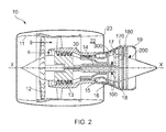
Figure 2 is a cross-section through a gas turbine engine having detection components, according to examples of the invention; -
Figure 3 is a schematic view of a part of a detection component showing a crack initiation feature in more detail; -
Figure 4A is a schematic view of a detection component comprising more than one crack initiation feature; -
Figure 4B is a schematic view of the detection component ofFigure 4A with cracks having formed from each of the crack initiation features; -
Figure 5 shows an example relationship between the life of a critical component and the life of a remote detection component; and -
Figure 6 is a schematic view of an example of a detection component in the form of a disc. - It is noted that the drawings may not be to scale. The drawings are intended to depict only typical aspects of the invention, and therefore should not be considered as limiting the scope of the invention. In the drawings, like numbering represents like elements between the drawings.
- With reference to
Figure 2 , a ducted fan gas turbine engine generally indicated at 10 has a principal and rotational axis X-X. Theengine 10 comprises, in axial flow series, anair intake 11, apropulsive fan 12, anintermediate pressure compressor 13, a high-pressure compressor 14,combustion equipment 15, a high-pressure turbine 16, andintermediate pressure turbine 17, a low-pressure turbine 18 and a coreengine exhaust nozzle 19. The engine also has abypass duct 22 and abypass exhaust nozzle 23. - The
gas turbine engine 10 works in a conventional manner so that air entering theintake 11 is accelerated by thefan 12 to produce two air flows: a first air flow A into theintermediate pressure compressor 13 and a second air flow B which passes through thebypass duct 22 to provide propulsive thrust. Theintermediate pressure compressor 13 compresses the air flow A directed into it before delivering that air to thehigh pressure compressor 14 where further compression takes place. - The compressed air exhausted from the high-
pressure compressor 14 is directed into thecombustion equipment 15 where it is mixed with fuel and the mixture combusted. The resultant hot combustion products then expand through, and thereby drive the high, intermediate and low-pressure turbines nozzle 19 to provide additional propulsive thrust. The high, intermediate and low-pressure turbines intermediate pressure compressors fan 12 by suitable interconnecting shafts. - As described above, the life of various components of the
gas turbine engine 10 may be critical to its operation. For example, each of the turbine stages 16, 17, 18 and each of the compressor stages 12, 13, 14 comprises aerofoil components that are attached to a rotating disc (such as the turbine discs labelled 170, 180 inFigure 2 ), and the rotating disc may be deemed to be critical to the operation of thegas turbine engine 10. As such, these rotating discs are examples of critical rotating components for which accurate estimation of the remaining serviceable life is advantageous. - To this end, the
gas turbine engine 10 is provided withdetection components Figure 2 . It will be appreciated that, whilst the gas turbine engine ofFigure 2 is shown as comprising threeseparate detection components such detection components - A
gas turbine engine 10 may comprise arotating detection component 100, as in the example shown inFigure 2 in which arotating detection component 100 is fixedly attached to (for example mounted to or mounted on) arotating shaft 30. Therotating detection component 100 may thus be configured to rotate at the same speed as theshaft 30 during use. The rotatingshaft 30 may also have at least one turbine and/or compressor rotor stage mounted thereon. Therotating detection component 100 may be used to predict the remaining serviceable life of a component that rotates at the same speed (for example a rotating component, such as aturbine disc 170, that is attached to the same shaft 30), or at a different speed (for example a rotating component, such as aturbine disc 180, that is attached to a different rotating shaft). The difference in shaft rotational speeds (for example between high pressure, low pressure and (where present) intermediate pressure shaft speeds) may be well known, for example from engine performance modelling, so thedetection component 100 and thecritical component rotating detection component 100 may itself be a disc or other feature that rotates with theshaft 30 in use. In some arrangements, the sole purpose of therotating detection component 100 may be in predicting the remaining serviceable life of a criticalrotating component - A
stationary detection component rotating detection component 100. In theFigure 2 example, twostationary detection components detection components 200 is adedicated detection component 200. The sole function of thededicated detection component 200 may be in predicting the remaining serviceable life of a criticalrotating component detection component dedicated detection component 200. - Alternatively, any
detection component stationary detection component 300 in theFigure 2 example. By way of example, a crack initiation feature (described in greater detail by way of example below) may be provided on a platform of a guide vane, such as a nozzle guide vane immediately downstream of thecombustor 15. - As described elsewhere herein, even though a
stationary detection component rotating component stationary detection component gas turbine engine 10. Accordingly, the stress experienced by a criticalrotating component 170, 180 (which is generally a function of rotational speed, temperature and pressure) in agas turbine engine 10 may be correlated to the stress experienced by astationary component static components high pressure compressors combustor 15, and theturbines rotating component - Each
detection component Figure 3 shows a detailed view of a part of adetection component crack initiation feature 50. In theFigure 3 example, thecrack initiation feature 50 is provided in the form of ahole 50 in thedetection component detection component detection component - The
crack initiation feature 50 is located apre-determined distance 54 from a free edge (or perimeter edge) 56 of thedetection component distance 54 is determined such that the resulting stress concentration factor at thehole 50 results in the initiation of acrack 60 after a given period (for example a given number of flight and/or engine cycles) of use of thedetection component crack 60 may be referred to as anon-dysfunctional crack 60, because its formation may not be critical to the operation of thedetection component detection component gas turbine engine 10. Due to the relative construction and arrangement of thedetection component rotating component non-dysfunctional crack 60 forms earlier than any meaningful deterioration (for example any uncontrolled crack formation) in the criticalrotating component - The desired size and positioning of the
crack initiation feature 50, required to produce a given stress concentration factor for example, may be determined by any known technique, such as by experiment and/or by an analytical modelling technique (such as, for example, finite element analysis). Accordingly, the expected stress concentration at thehole 50 during use may be well known and understood. Accordingly, the appearance of anon-dysfunctional crack 60 in thedetection component detection component detection component - In use, the detection component(s) 100, 200, 300 may be inspected for the appearance of a
crack 60 at thecrack initiation feature 50, at pre-determined intervals. For example, the intervals may correspond to service intervals, which may be determined in any suitable manner, for example on the basis of the number of hours for which thegas turbine engine 10 has been in operation and/or the number of cycles of the engine. The inspection may take any suitable form such as, for example, a visual inspection. Purely by way of example, a boroscope may be used to perform the inspection. - If a
crack 60 is detected in thedetection component critical component crack 60 appeared immediately after the previous inspection. This would be a particularly cautious approach, and it will be appreciated that other approaches are possible. For example, it may be possible to estimate from the crack 60 (for example from its size, such as its length) the age of the crack (for example in terms of engine cycles), and thus when thecrack 60 formed. This may allow a more accurate estimation of the remaining serviceable life of thecritical component - By way of example, one possible approach, which could be applied to any embodiment, is to determine that a
crack 60 has formed at thecrack initiation feature 50 if and only if thecrack 60 extends from thecrack initiation feature 50 to aperimeter edge 56 of thedetection component Figure 3 example. This may provide a particularly repeatable technique for determining whether acrack 60 has formed. However, it will be appreciated that other approaches are possible, for example determining whether acrack 60 of any detectable size has formed, or determining whether acrack 60 over a certain size (for example length) has formed. - Any one or
more detection components Figures 4A and 4B show a portion of adetection component crack initiation feature 50 ofFigure 3 . As such, each of the crack initiation features 150, 152, 154, 156 may be a hole. In alternative arrangements, any one or more of the crack initiation features 150, 152, 154, 156 may take a different form such as, by way of example only, a notch, a groove, a boss, a flange, or a slot, such as would be used in a standard crack test specimen, for example. - The stress concentration may be different for each of the crack initiation features 150, 152, 154, 156. For example, in the arrangement of
Figures 4A and 4B , each of the plurality of crack initiation features 150, 152, 154, 156 may be positioned a successivelygreater distance perimeter edge 56 of thedetection component crack initiation feature Figures 4A and 4B , as the distance from the respectivecrack initiation feature perimeter edge 56 decreases. - As mentioned in relation to
Figure 3 , the expected stress concentration at eachcrack initiation feature non-dysfunctional crack crack initiation feature component 100 such that corresponding non-dysfunctional cracks 162,164,166 are initiated following successive periods of operation of thecomponent 100. - Accordingly, the appearance of a
non-dysfunctional crack 160 originating at a firstcrack initiation feature 150 in thedetection component detection component non-dysfunctional cracks - For the formation of each non-dysfunctional crack, the stress history of the
detection component rotating component rotating component non-dysfunctional crack 160, and subsequent (second, third, fourth and so on) estimations of the remaining serviceable life may be estimated after the formation of subsequent non-dysfunctional cracks from the crack initiation features 152, 154, 156 having successively lower stress concentrations. This may allow a particularly accurate estimation of the remaining serviceable life of acritical component crack 166 is detected at thecrack initiation feature 156 having the lowest stress concentration, the criticalrotating component crack initiation feature 156 with the lowest stress concentration may be a fail-safe feature which indicates that a critical component may need to be replaced immediately. - As mentioned elsewhere herein, the
detection component critical component - The
detection component rotating component detection component -
Figure 5 is an illustrative example of the correlation between the life (which may be any suitable measure, such as number of cycles) of adetection component critical component detection component crack 60 appears from a respectivecrack initiation feature 50 and thus may or may not represent the actual serviceable life of thedetection component Figure 5 is purely by way of an example of how the life of the two components may be related, and that other explanations may be used. - The overstress α in
Figure 5 represents the additional stress experienced by thedetection component critical component - If the same material (for example same base material and same manufacturing process) is used for the
detection component critical component detection component critical component detection component critical component 170, 180) inFigure 5 . For a different material the relationship may be a curve, as shown inFigure 5 between the points A and B'. By way of example, empirical and/or experimental data may be used to generate the relationship between the stress and life for a given material. - In some arrangements a different material may be used for the
detection component critical component Figure 5 , a correction may be used to take the estimated life of thecritical component Figure 5 to point C may be in either direction (i.e. longer or shorter life), depending on the relative material properties. It will also be appreciated that the estimated life at point C of thecritical component detection component - Even if the same material and manufacturing process are used for the
detection component critical component critical component figure 5 , from point B towards (or to) point C. - Even if the
detection component critical component critical component detection component Figure 5 to the left. Using a greater number ofdetection components critical component -
Figure 6 is a more detailed schematic view of adetection component 100, which may represent, for example, the rotatingdetection component 100 shown inFigure 2 . The features shown inFigure 6 that correspond to features described in relation to other figures are given like reference numerals. - In the
Figure 6 arrangement, thedetection component 100 may be a rotational component that rotates about an axis X-X, which may correspond to the axis X-X of agas turbine engine 10. Thedetection component 100 may have an annular shape when viewed along its rotational axis X-X, and may be referred to as a disc, a detection disc, or a mini-disc. The mass (and/or rotational moment of inertia) of thedisc 100 may be less than that of the criticalrotating component disc 100 may be sufficiently low that if it were to fail (for example break apart), then it would be contained within the engine. As such, adetection disc 100 may be classified as a non-critical part. Thedetection component 100 may be attached to arotating shaft 30 of thegas turbine engine 10 using, for example, a mechanical fixing 32, as in theFigure 6 example. - The
detection component 100 is shown as having acrack initiation feature 50 near to its outerradial surface 56, which may be an example of aperimeter surface 56 as referred to elsewhere herein. However, it will be appreciated that one or more crack initiation features 50 could be provided in additional or alternative locations on thedetection component 100. For example, a plurality of crack initiation features 50 may be provided at different angular positions around thedetection component 100. As described elsewhere herein, eachcrack initiation feature 50 may be provided at different distances from theperimeter edge 56 to other crack initiation features 50. - The methods and/or apparatus described herein may be used to estimate the remaining serviceable life of any critical component in any engine, for example a turbofan, turbojet, turbo-prop or open-rotor gas turbine engine. Such a gas turbine engine may be for any use, for example for aircraft propulsion, industrial power generation, or marine use. Furthermore, the foregoing description of various aspects of the invention has been presented for purposes of illustration and description. It is not intended to be exhaustive or to limit the invention to the precise form disclosed. Various modifications and variations that may be apparent to a person of skill in the art are included within the scope of the invention as defined by the accompanying claims. Purely by way of non-limitative example, such variations may include the form and arrangement of detection components and/or crack initiation features.
Claims (15)
- A method of predicting a remaining serviceable life of a critical rotating component (170, 180) of a gas turbine engine (10) comprising:providing a detection component (100, 200, 300) in the gas turbine engine with a crack initiation feature (50), the detection component being remote from the critical rotating component;inspecting the detection component to determine whether a crack has formed at the crack initiation feature; andestimating a remaining serviceable life of the critical rotating component based on whether a crack has formed at the crack-initiation feature.
- A method of predicting a remaining serviceable life of a critical rotating component according to claim 1, wherein:the detection component has a perimeter edge (56); anda crack is determined to have formed at the crack initiation feature only if the crack extends from the crack initiation feature to the perimeter edge.
- A method of predicting a remaining serviceable life of a critical rotating component according to claim 1 or claim 2, comprising:providing the detection component with first and second crack initiation features (150, 152) provided at respective first and second distances (122, 124) from a perimeter edge of the detection component, the first distance being less than the second distance; andproviding a first estimation of remaining serviceable life of the critical component based on crack formation (160) at the first crack initiation feature; andproviding a second estimation of remaining serviceable life of the critical component based on crack formation (162) at the second crack initiation feature.
- A method of predicting a remaining serviceable life of a critical rotating component according to any one of the preceding claims, comprising:providing the detection component with a plurality of crack initiation features (150, 152, 154, 156) at respective distances (122, 124, 126, 128) from a perimeter edge of the detection component; andproviding a plurality of respective estimations of remaining serviceable life of the critical component based on crack formation (160, 162, 164, 166) at each of the crack initiation features.
- A method of predicting a remaining serviceable life of a critical rotating component according to any one of the preceding claims, wherein the step of estimating a remaining serviceable life of the critical rotating component comprises consideration of at least one of:the geometry of the detection component, the geometry of the or each crack initiation feature and the geometry of the critical rotating component;the location of the detection component and the location of the critical rotating component in the gas turbine engine; andthe material of the detection component and the material of the critical rotating component.
- A method of predicting a remaining serviceable life of a critical rotating component according to any one of the preceding claims, wherein the steps of inspecting the detection component and estimating a remaining serviceable life of the critical rotating component are performed at predetermined intervals.
- A gas turbine engine (10) comprising:a critical rotating component (170, 180) that is critical to the operation of the gas turbine engine;a detection component (100, 200, 300) that is provided with a crack initiation feature (50) and is remote from the critical rotating component, wherein:the crack initiation feature is arranged such that, in use, formation of a crack (60) at the crack initiation feature is correlated to the remaining serviceable life of the critical rotating component.
- A gas turbine engine according to claim 7, wherein:the detection component has a perimeter edge (56); anda crack is determined to have formed at the crack-initiation feature only if the crack extends from the crack initiation feature to the perimeter edge.
- A gas turbine engine according to claim 7 or claim 8, wherein the detection component comprises a plurality of crack-initiation features (150, 152, 154, 156).
- A gas turbine engine according to claim 9, wherein:the detection component comprises a perimeter edge (56);each crack initiation feature is provided at a respective distance (122, 124, 126, 128) from the perimeter edge; andthe respective distance of at least one crack initiation feature from the perimeter edge is different to the respective distance of another crack initiation feature from the perimeter edge.
- A gas turbine engine according to any one of claims 7 to 10, wherein the detection component is constructed and arranged to remain as a single unit in the event of crack formation at one or more crack initiation features.
- A gas turbine engine according to any one of claims 7 to 11, wherein:the gas turbine engine defines a core flow path (A), and the detection component is a stationary component (200, 300) placed in core flow path, wherein, optionally:the detection component is a stationary vane (300) having a platform and an aerofoil portion; and the crack initiation feature is provided on the platform.
- A gas turbine engine according to any one of claims 7 to 11, wherein:the detection component is a rotating component (100), wherein, optionally:the detection component is a rotating blade having a platform and an aerofoil portion; and the crack initiation feature is provided on the platform; orthe detection component is a disc connected to a rotating shaft of the gas turbine engine, the disc optionally having substantially no impact on gas flow through the gas turbine engine.
- A gas turbine engine according to any one of claims 7 to 13 comprising more than one detection component.
- A gas turbine engine according to any one of claims 7 to 14 or a method according to any one of claims 1 to 6, wherein:the critical rotating component is a rotating disc (170, 180) that carries rotating blades of the gas turbine engine; and/orthe crack initiation feature is one of: a hole, a notch, a groove, a boss, a flange or a propagation slot.
Applications Claiming Priority (1)
| Application Number | Priority Date | Filing Date | Title |
|---|---|---|---|
| GBGB1402597.7A GB201402597D0 (en) | 2014-02-14 | 2014-02-14 | Method and system for predicting the serviceable life of a component |
Publications (2)
| Publication Number | Publication Date |
|---|---|
| EP2908115A1 true EP2908115A1 (en) | 2015-08-19 |
| EP2908115B1 EP2908115B1 (en) | 2017-07-26 |
Family
ID=50440145
Family Applications (1)
| Application Number | Title | Priority Date | Filing Date |
|---|---|---|---|
| EP15151772.9A Active EP2908115B1 (en) | 2014-02-14 | 2015-01-20 | Method and system for predicting the serviceable life of a component |
Country Status (3)
| Country | Link |
|---|---|
| US (1) | US9885636B2 (en) |
| EP (1) | EP2908115B1 (en) |
| GB (1) | GB201402597D0 (en) |
Cited By (3)
| Publication number | Priority date | Publication date | Assignee | Title |
|---|---|---|---|---|
| EP3352034A1 (en) * | 2017-01-23 | 2018-07-25 | United Technologies Corporation | Classification of gas turbine engine components |
| CN108709748A (en) * | 2018-05-31 | 2018-10-26 | 中国民航大学 | Small aero multiple spot impact-rub malfunction analogue experiment installation |
| FR3115489A1 (en) * | 2020-10-28 | 2022-04-29 | Safran | Fibrous textures with a privileged breaking zone |
Families Citing this family (8)
| Publication number | Priority date | Publication date | Assignee | Title |
|---|---|---|---|---|
| US9617010B2 (en) | 2014-03-28 | 2017-04-11 | Bell Helicopter Textron Inc. | Aircraft prognostics health system |
| US10626748B2 (en) * | 2014-12-08 | 2020-04-21 | General Electric Company | System and method for predicting and managing life consumption of gas turbine parts |
| JP6892753B2 (en) * | 2016-12-02 | 2021-06-23 | 三菱パワー株式会社 | Equipment state estimation device, equipment state estimation method and program |
| GB201804420D0 (en) | 2018-03-20 | 2018-05-02 | Rolls Royce Plc | A gas turbine engine having a metallic test sample and a method of dertermining the service life of a gas turbine engine component using a metallic sample |
| US11305894B2 (en) * | 2018-11-30 | 2022-04-19 | Gulfstream Aerospace Corporation | Detection of fan case liner damage during turbine engine operation |
| US11703421B2 (en) | 2019-01-31 | 2023-07-18 | Pratt & Whitney Canada Corp. | System and method for validating component integrity in an engine |
| CN109977462B (en) * | 2019-02-17 | 2023-01-24 | 中国科学院工程热物理研究所 | Wheel disc low-cycle fatigue life prediction method considering surface initial machining tool marks |
| US20230039760A1 (en) * | 2021-08-04 | 2023-02-09 | Pratt & Whitney Canada Corp. | System and method for monitoring life limit of engine components |
Citations (3)
| Publication number | Priority date | Publication date | Assignee | Title |
|---|---|---|---|---|
| US5520055A (en) * | 1993-11-13 | 1996-05-28 | Dornier Gmbh | Apparatus for monitoring the fatigue strength of structures |
| US20020019708A1 (en) * | 1999-12-23 | 2002-02-14 | Jorg Pross | Method for monitoring the creep behavior of rotating components of a compressor stage or turbine stage |
| US20080145223A1 (en) * | 2004-03-16 | 2008-06-19 | Christian Hohmann | Method and Device For Identifying the State of the Rotor of a Non-Positive-Displacement Machine |
Family Cites Families (11)
| Publication number | Priority date | Publication date | Assignee | Title |
|---|---|---|---|---|
| JP3020162B1 (en) * | 1998-12-17 | 2000-03-15 | 広島大学長 | Sacrificial specimen for long-term stress monitoring of structures and method of use |
| DE19918219C1 (en) * | 1999-04-22 | 2001-01-18 | Dornier Gmbh | Service life indicator for highly stressed lightweight structures |
| GB0513901D0 (en) | 2005-07-06 | 2005-08-10 | Airbus Uk Ltd | Method and apparatus for measuring the structural integrity of a safe-life aircraft component |
| US7824147B2 (en) | 2006-05-16 | 2010-11-02 | United Technologies Corporation | Airfoil prognosis for turbine engines |
| US7493809B1 (en) * | 2007-10-04 | 2009-02-24 | General Electric Company | Method and system for measuring deformation in turbine blades |
| US8510061B2 (en) * | 2008-08-01 | 2013-08-13 | North Carolina State University | Methods, systems, and computer readable media for wireless crack detection and monitoring |
| US8694269B2 (en) * | 2008-08-11 | 2014-04-08 | The Boeing Company | Reducing the ringing of actuator elements in ultrasound based health monitoring systems |
| US9103741B2 (en) * | 2010-08-27 | 2015-08-11 | General Electric Company | Methods and systems for assessing residual life of turbomachine airfoils |
| US8784056B2 (en) | 2011-05-18 | 2014-07-22 | General Electric Company | System and turbine including creep indicating member |
| US8746049B2 (en) * | 2011-09-06 | 2014-06-10 | General Electric Company | Creep indication system and method for determining creep amount |
| GB201216787D0 (en) * | 2012-09-20 | 2012-11-07 | Rolls Royce Plc | Method and system for predicting the serviceable life of a component |
-
2014
- 2014-02-14 GB GBGB1402597.7A patent/GB201402597D0/en not_active Ceased
-
2015
- 2015-01-20 EP EP15151772.9A patent/EP2908115B1/en active Active
- 2015-01-21 US US14/601,889 patent/US9885636B2/en active Active
Patent Citations (3)
| Publication number | Priority date | Publication date | Assignee | Title |
|---|---|---|---|---|
| US5520055A (en) * | 1993-11-13 | 1996-05-28 | Dornier Gmbh | Apparatus for monitoring the fatigue strength of structures |
| US20020019708A1 (en) * | 1999-12-23 | 2002-02-14 | Jorg Pross | Method for monitoring the creep behavior of rotating components of a compressor stage or turbine stage |
| US20080145223A1 (en) * | 2004-03-16 | 2008-06-19 | Christian Hohmann | Method and Device For Identifying the State of the Rotor of a Non-Positive-Displacement Machine |
Cited By (3)
| Publication number | Priority date | Publication date | Assignee | Title |
|---|---|---|---|---|
| EP3352034A1 (en) * | 2017-01-23 | 2018-07-25 | United Technologies Corporation | Classification of gas turbine engine components |
| CN108709748A (en) * | 2018-05-31 | 2018-10-26 | 中国民航大学 | Small aero multiple spot impact-rub malfunction analogue experiment installation |
| FR3115489A1 (en) * | 2020-10-28 | 2022-04-29 | Safran | Fibrous textures with a privileged breaking zone |
Also Published As
| Publication number | Publication date |
|---|---|
| GB201402597D0 (en) | 2014-04-02 |
| EP2908115B1 (en) | 2017-07-26 |
| US9885636B2 (en) | 2018-02-06 |
| US20150233789A1 (en) | 2015-08-20 |
Similar Documents
| Publication | Publication Date | Title |
|---|---|---|
| EP2908115B1 (en) | Method and system for predicting the serviceable life of a component | |
| US8918264B2 (en) | Method and device for monitoring a turbine engine of an aircraft | |
| Madhavan et al. | Vibration based damage detection of rotor blades in a gas turbine engine | |
| EP3361229B1 (en) | System and method for blade health monitoring | |
| CN107667280B (en) | Scheduled inspection and predicted end-of-life of machine components | |
| US10030534B2 (en) | Detectable datum markers for gas turbine engine components for measuring distortion | |
| US6932560B2 (en) | Apparatus and method for detecting an impact on a rotor blade | |
| US20160061050A1 (en) | Wear monitor for a gas turbine engine | |
| Balli | Failure analysis of inlet guide vane (IGV) actuator and bellcrank assembly used on J85 turbojet engines | |
| Witoś et al. | Turbine engine health/Maintenance status monitoring with use of phase-discrete method of blade vibration monitoring | |
| CA2738202A1 (en) | Device and method for service-life monitoring | |
| US20120215509A1 (en) | Method for the detection of failures in a turbomachine by means of a theoretical model of the thermodynamic cycle of the said turbomachine | |
| Saraçyakupoğlu | Failure analysis of J85-CAN-15 turbojet engine compressor disc | |
| EP2711679A2 (en) | Method and system for predicting the serviceable life of a component | |
| CN107976482A (en) | The crackle in-situ monitor system and method for disk-like accessory in life assessment test | |
| RU2439527C2 (en) | Method of operating aircraft gas turbine engine according to its technical state | |
| Fox et al. | Fan Blade Fatigue Fractures in CFM56-7B Engines | |
| Cardinale et al. | Experimental verification of turboblading aeromechanics | |
| RU2696523C1 (en) | Method of operating an aircraft gas turbine engine based on its technical state | |
| Vijaya Lakshmi et al. | Condition Assessment of Strain-Gauged Aero Engine Compressor Stator Vanes Using Eddy Current Testing | |
| Chana et al. | Disk crack detection and prognosis using non contact time of arrival sensors | |
| EP3543474A1 (en) | A gas turbine engine having a metallic test sample and a method of determining the service life of a gas turbine engine component using a metallic test sample | |
| RU2742321C1 (en) | Method of operating aircraft gas turbine engine based on technical state thereof | |
| RU2796563C1 (en) | Method for operation of an aircraft gas turbine according to its technical condition | |
| EP4170134A1 (en) | Gas passage |
Legal Events
| Date | Code | Title | Description |
|---|---|---|---|
| PUAI | Public reference made under article 153(3) epc to a published international application that has entered the european phase |
Free format text: ORIGINAL CODE: 0009012 |
|
| AK | Designated contracting states |
Kind code of ref document: A1 Designated state(s): AL AT BE BG CH CY CZ DE DK EE ES FI FR GB GR HR HU IE IS IT LI LT LU LV MC MK MT NL NO PL PT RO RS SE SI SK SM TR |
|
| AX | Request for extension of the european patent |
Extension state: BA ME |
|
| 17P | Request for examination filed |
Effective date: 20160216 |
|
| RBV | Designated contracting states (corrected) |
Designated state(s): AL AT BE BG CH CY CZ DE DK EE ES FI FR GB GR HR HU IE IS IT LI LT LU LV MC MK MT NL NO PL PT RO RS SE SI SK SM TR |
|
| 17Q | First examination report despatched |
Effective date: 20160826 |
|
| GRAP | Despatch of communication of intention to grant a patent |
Free format text: ORIGINAL CODE: EPIDOSNIGR1 |
|
| INTG | Intention to grant announced |
Effective date: 20170517 |
|
| GRAS | Grant fee paid |
Free format text: ORIGINAL CODE: EPIDOSNIGR3 |
|
| GRAA | (expected) grant |
Free format text: ORIGINAL CODE: 0009210 |
|
| AK | Designated contracting states |
Kind code of ref document: B1 Designated state(s): AL AT BE BG CH CY CZ DE DK EE ES FI FR GB GR HR HU IE IS IT LI LT LU LV MC MK MT NL NO PL PT RO RS SE SI SK SM TR |
|
| REG | Reference to a national code |
Ref country code: GB Ref legal event code: FG4D |
|
| REG | Reference to a national code |
Ref country code: CH Ref legal event code: EP |
|
| REG | Reference to a national code |
Ref country code: AT Ref legal event code: REF Ref document number: 912766 Country of ref document: AT Kind code of ref document: T Effective date: 20170815 |
|
| REG | Reference to a national code |
Ref country code: IE Ref legal event code: FG4D |
|
| REG | Reference to a national code |
Ref country code: DE Ref legal event code: R096 Ref document number: 602015003694 Country of ref document: DE |
|
| REG | Reference to a national code |
Ref country code: NL Ref legal event code: MP Effective date: 20170726 |
|
| REG | Reference to a national code |
Ref country code: LT Ref legal event code: MG4D |
|
| REG | Reference to a national code |
Ref country code: AT Ref legal event code: MK05 Ref document number: 912766 Country of ref document: AT Kind code of ref document: T Effective date: 20170726 |
|
| REG | Reference to a national code |
Ref country code: FR Ref legal event code: PLFP Year of fee payment: 4 |
|
| PG25 | Lapsed in a contracting state [announced via postgrant information from national office to epo] |
Ref country code: LT Free format text: LAPSE BECAUSE OF FAILURE TO SUBMIT A TRANSLATION OF THE DESCRIPTION OR TO PAY THE FEE WITHIN THE PRESCRIBED TIME-LIMIT Effective date: 20170726 Ref country code: SE Free format text: LAPSE BECAUSE OF FAILURE TO SUBMIT A TRANSLATION OF THE DESCRIPTION OR TO PAY THE FEE WITHIN THE PRESCRIBED TIME-LIMIT Effective date: 20170726 Ref country code: HR Free format text: LAPSE BECAUSE OF FAILURE TO SUBMIT A TRANSLATION OF THE DESCRIPTION OR TO PAY THE FEE WITHIN THE PRESCRIBED TIME-LIMIT Effective date: 20170726 Ref country code: NO Free format text: LAPSE BECAUSE OF FAILURE TO SUBMIT A TRANSLATION OF THE DESCRIPTION OR TO PAY THE FEE WITHIN THE PRESCRIBED TIME-LIMIT Effective date: 20171026 Ref country code: NL Free format text: LAPSE BECAUSE OF FAILURE TO SUBMIT A TRANSLATION OF THE DESCRIPTION OR TO PAY THE FEE WITHIN THE PRESCRIBED TIME-LIMIT Effective date: 20170726 Ref country code: AT Free format text: LAPSE BECAUSE OF FAILURE TO SUBMIT A TRANSLATION OF THE DESCRIPTION OR TO PAY THE FEE WITHIN THE PRESCRIBED TIME-LIMIT Effective date: 20170726 Ref country code: FI Free format text: LAPSE BECAUSE OF FAILURE TO SUBMIT A TRANSLATION OF THE DESCRIPTION OR TO PAY THE FEE WITHIN THE PRESCRIBED TIME-LIMIT Effective date: 20170726 |
|
| PG25 | Lapsed in a contracting state [announced via postgrant information from national office to epo] |
Ref country code: PL Free format text: LAPSE BECAUSE OF FAILURE TO SUBMIT A TRANSLATION OF THE DESCRIPTION OR TO PAY THE FEE WITHIN THE PRESCRIBED TIME-LIMIT Effective date: 20170726 Ref country code: ES Free format text: LAPSE BECAUSE OF FAILURE TO SUBMIT A TRANSLATION OF THE DESCRIPTION OR TO PAY THE FEE WITHIN THE PRESCRIBED TIME-LIMIT Effective date: 20170726 Ref country code: LV Free format text: LAPSE BECAUSE OF FAILURE TO SUBMIT A TRANSLATION OF THE DESCRIPTION OR TO PAY THE FEE WITHIN THE PRESCRIBED TIME-LIMIT Effective date: 20170726 Ref country code: BG Free format text: LAPSE BECAUSE OF FAILURE TO SUBMIT A TRANSLATION OF THE DESCRIPTION OR TO PAY THE FEE WITHIN THE PRESCRIBED TIME-LIMIT Effective date: 20171026 Ref country code: RS Free format text: LAPSE BECAUSE OF FAILURE TO SUBMIT A TRANSLATION OF THE DESCRIPTION OR TO PAY THE FEE WITHIN THE PRESCRIBED TIME-LIMIT Effective date: 20170726 Ref country code: GR Free format text: LAPSE BECAUSE OF FAILURE TO SUBMIT A TRANSLATION OF THE DESCRIPTION OR TO PAY THE FEE WITHIN THE PRESCRIBED TIME-LIMIT Effective date: 20171027 Ref country code: IS Free format text: LAPSE BECAUSE OF FAILURE TO SUBMIT A TRANSLATION OF THE DESCRIPTION OR TO PAY THE FEE WITHIN THE PRESCRIBED TIME-LIMIT Effective date: 20171126 |
|
| PG25 | Lapsed in a contracting state [announced via postgrant information from national office to epo] |
Ref country code: CZ Free format text: LAPSE BECAUSE OF FAILURE TO SUBMIT A TRANSLATION OF THE DESCRIPTION OR TO PAY THE FEE WITHIN THE PRESCRIBED TIME-LIMIT Effective date: 20170726 Ref country code: DK Free format text: LAPSE BECAUSE OF FAILURE TO SUBMIT A TRANSLATION OF THE DESCRIPTION OR TO PAY THE FEE WITHIN THE PRESCRIBED TIME-LIMIT Effective date: 20170726 Ref country code: RO Free format text: LAPSE BECAUSE OF FAILURE TO SUBMIT A TRANSLATION OF THE DESCRIPTION OR TO PAY THE FEE WITHIN THE PRESCRIBED TIME-LIMIT Effective date: 20170726 |
|
| REG | Reference to a national code |
Ref country code: DE Ref legal event code: R097 Ref document number: 602015003694 Country of ref document: DE |
|
| PG25 | Lapsed in a contracting state [announced via postgrant information from national office to epo] |
Ref country code: IT Free format text: LAPSE BECAUSE OF FAILURE TO SUBMIT A TRANSLATION OF THE DESCRIPTION OR TO PAY THE FEE WITHIN THE PRESCRIBED TIME-LIMIT Effective date: 20170726 Ref country code: SM Free format text: LAPSE BECAUSE OF FAILURE TO SUBMIT A TRANSLATION OF THE DESCRIPTION OR TO PAY THE FEE WITHIN THE PRESCRIBED TIME-LIMIT Effective date: 20170726 Ref country code: EE Free format text: LAPSE BECAUSE OF FAILURE TO SUBMIT A TRANSLATION OF THE DESCRIPTION OR TO PAY THE FEE WITHIN THE PRESCRIBED TIME-LIMIT Effective date: 20170726 Ref country code: SK Free format text: LAPSE BECAUSE OF FAILURE TO SUBMIT A TRANSLATION OF THE DESCRIPTION OR TO PAY THE FEE WITHIN THE PRESCRIBED TIME-LIMIT Effective date: 20170726 |
|
| PLBE | No opposition filed within time limit |
Free format text: ORIGINAL CODE: 0009261 |
|
| STAA | Information on the status of an ep patent application or granted ep patent |
Free format text: STATUS: NO OPPOSITION FILED WITHIN TIME LIMIT |
|
| 26N | No opposition filed |
Effective date: 20180430 |
|
| PG25 | Lapsed in a contracting state [announced via postgrant information from national office to epo] |
Ref country code: SI Free format text: LAPSE BECAUSE OF FAILURE TO SUBMIT A TRANSLATION OF THE DESCRIPTION OR TO PAY THE FEE WITHIN THE PRESCRIBED TIME-LIMIT Effective date: 20170726 |
|
| REG | Reference to a national code |
Ref country code: CH Ref legal event code: PL |
|
| PG25 | Lapsed in a contracting state [announced via postgrant information from national office to epo] |
Ref country code: LU Free format text: LAPSE BECAUSE OF NON-PAYMENT OF DUE FEES Effective date: 20180120 |
|
| REG | Reference to a national code |
Ref country code: IE Ref legal event code: MM4A |
|
| REG | Reference to a national code |
Ref country code: BE Ref legal event code: MM Effective date: 20180131 |
|
| PG25 | Lapsed in a contracting state [announced via postgrant information from national office to epo] |
Ref country code: LI Free format text: LAPSE BECAUSE OF NON-PAYMENT OF DUE FEES Effective date: 20180131 Ref country code: CH Free format text: LAPSE BECAUSE OF NON-PAYMENT OF DUE FEES Effective date: 20180131 Ref country code: BE Free format text: LAPSE BECAUSE OF NON-PAYMENT OF DUE FEES Effective date: 20180131 |
|
| PG25 | Lapsed in a contracting state [announced via postgrant information from national office to epo] |
Ref country code: IE Free format text: LAPSE BECAUSE OF NON-PAYMENT OF DUE FEES Effective date: 20180120 |
|
| PG25 | Lapsed in a contracting state [announced via postgrant information from national office to epo] |
Ref country code: MC Free format text: LAPSE BECAUSE OF FAILURE TO SUBMIT A TRANSLATION OF THE DESCRIPTION OR TO PAY THE FEE WITHIN THE PRESCRIBED TIME-LIMIT Effective date: 20170726 |
|
| PG25 | Lapsed in a contracting state [announced via postgrant information from national office to epo] |
Ref country code: MT Free format text: LAPSE BECAUSE OF NON-PAYMENT OF DUE FEES Effective date: 20180120 |
|
| PG25 | Lapsed in a contracting state [announced via postgrant information from national office to epo] |
Ref country code: TR Free format text: LAPSE BECAUSE OF FAILURE TO SUBMIT A TRANSLATION OF THE DESCRIPTION OR TO PAY THE FEE WITHIN THE PRESCRIBED TIME-LIMIT Effective date: 20170726 |
|
| PG25 | Lapsed in a contracting state [announced via postgrant information from national office to epo] |
Ref country code: PT Free format text: LAPSE BECAUSE OF FAILURE TO SUBMIT A TRANSLATION OF THE DESCRIPTION OR TO PAY THE FEE WITHIN THE PRESCRIBED TIME-LIMIT Effective date: 20170726 |
|
| PG25 | Lapsed in a contracting state [announced via postgrant information from national office to epo] |
Ref country code: HU Free format text: LAPSE BECAUSE OF FAILURE TO SUBMIT A TRANSLATION OF THE DESCRIPTION OR TO PAY THE FEE WITHIN THE PRESCRIBED TIME-LIMIT; INVALID AB INITIO Effective date: 20150120 Ref country code: MK Free format text: LAPSE BECAUSE OF NON-PAYMENT OF DUE FEES Effective date: 20170726 Ref country code: CY Free format text: LAPSE BECAUSE OF FAILURE TO SUBMIT A TRANSLATION OF THE DESCRIPTION OR TO PAY THE FEE WITHIN THE PRESCRIBED TIME-LIMIT Effective date: 20170726 |
|
| PG25 | Lapsed in a contracting state [announced via postgrant information from national office to epo] |
Ref country code: AL Free format text: LAPSE BECAUSE OF FAILURE TO SUBMIT A TRANSLATION OF THE DESCRIPTION OR TO PAY THE FEE WITHIN THE PRESCRIBED TIME-LIMIT Effective date: 20170726 |
|
| PGFP | Annual fee paid to national office [announced via postgrant information from national office to epo] |
Ref country code: FR Payment date: 20230124 Year of fee payment: 9 |
|
| P01 | Opt-out of the competence of the unified patent court (upc) registered |
Effective date: 20230528 |
|
| PGFP | Annual fee paid to national office [announced via postgrant information from national office to epo] |
Ref country code: DE Payment date: 20240129 Year of fee payment: 10 Ref country code: GB Payment date: 20240123 Year of fee payment: 10 |