EP3351923A1 - Reduction in dew formation by preparing specimen for investigation - Google Patents
Reduction in dew formation by preparing specimen for investigation Download PDFInfo
- Publication number
- EP3351923A1 EP3351923A1 EP18152594.0A EP18152594A EP3351923A1 EP 3351923 A1 EP3351923 A1 EP 3351923A1 EP 18152594 A EP18152594 A EP 18152594A EP 3351923 A1 EP3351923 A1 EP 3351923A1
- Authority
- EP
- European Patent Office
- Prior art keywords
- specimen
- chamber
- nozzle
- pressure
- gas pressure
- Prior art date
- Legal status (The legal status is an assumption and is not a legal conclusion. Google has not performed a legal analysis and makes no representation as to the accuracy of the status listed.)
- Granted
Links
Images




Classifications
-
- G—PHYSICS
- G01—MEASURING; TESTING
- G01N—INVESTIGATING OR ANALYSING MATERIALS BY DETERMINING THEIR CHEMICAL OR PHYSICAL PROPERTIES
- G01N1/00—Sampling; Preparing specimens for investigation
- G01N1/28—Preparing specimens for investigation including physical details of (bio-)chemical methods covered elsewhere, e.g. G01N33/50, C12Q
- G01N1/30—Staining; Impregnating ; Fixation; Dehydration; Multistep processes for preparing samples of tissue, cell or nucleic acid material and the like for analysis
- G01N1/31—Apparatus therefor
-
- G—PHYSICS
- G01—MEASURING; TESTING
- G01N—INVESTIGATING OR ANALYSING MATERIALS BY DETERMINING THEIR CHEMICAL OR PHYSICAL PROPERTIES
- G01N1/00—Sampling; Preparing specimens for investigation
- G01N1/28—Preparing specimens for investigation including physical details of (bio-)chemical methods covered elsewhere, e.g. G01N33/50, C12Q
-
- G—PHYSICS
- G01—MEASURING; TESTING
- G01N—INVESTIGATING OR ANALYSING MATERIALS BY DETERMINING THEIR CHEMICAL OR PHYSICAL PROPERTIES
- G01N1/00—Sampling; Preparing specimens for investigation
- G01N1/28—Preparing specimens for investigation including physical details of (bio-)chemical methods covered elsewhere, e.g. G01N33/50, C12Q
- G01N1/40—Concentrating samples
- G01N1/4022—Concentrating samples by thermal techniques; Phase changes
-
- G—PHYSICS
- G01—MEASURING; TESTING
- G01N—INVESTIGATING OR ANALYSING MATERIALS BY DETERMINING THEIR CHEMICAL OR PHYSICAL PROPERTIES
- G01N1/00—Sampling; Preparing specimens for investigation
- G01N1/28—Preparing specimens for investigation including physical details of (bio-)chemical methods covered elsewhere, e.g. G01N33/50, C12Q
- G01N1/42—Low-temperature sample treatment, e.g. cryofixation
-
- G—PHYSICS
- G01—MEASURING; TESTING
- G01N—INVESTIGATING OR ANALYSING MATERIALS BY DETERMINING THEIR CHEMICAL OR PHYSICAL PROPERTIES
- G01N35/00—Automatic analysis not limited to methods or materials provided for in any single one of groups G01N1/00 - G01N33/00; Handling materials therefor
- G01N35/00029—Automatic analysis not limited to methods or materials provided for in any single one of groups G01N1/00 - G01N33/00; Handling materials therefor provided with flat sample substrates, e.g. slides
-
- B—PERFORMING OPERATIONS; TRANSPORTING
- B01—PHYSICAL OR CHEMICAL PROCESSES OR APPARATUS IN GENERAL
- B01D—SEPARATION
- B01D1/00—Evaporating
- B01D1/22—Evaporating by bringing a thin layer of the liquid into contact with a heated surface
- B01D1/24—Evaporating by bringing a thin layer of the liquid into contact with a heated surface to obtain dry solids
-
- B—PERFORMING OPERATIONS; TRANSPORTING
- B01—PHYSICAL OR CHEMICAL PROCESSES OR APPARATUS IN GENERAL
- B01L—CHEMICAL OR PHYSICAL LABORATORY APPARATUS FOR GENERAL USE
- B01L3/00—Containers or dishes for laboratory use, e.g. laboratory glassware; Droppers
-
- B—PERFORMING OPERATIONS; TRANSPORTING
- B65—CONVEYING; PACKING; STORING; HANDLING THIN OR FILAMENTARY MATERIAL
- B65B—MACHINES, APPARATUS OR DEVICES FOR, OR METHODS OF, PACKAGING ARTICLES OR MATERIALS; UNPACKING
- B65B1/00—Packaging fluent solid material, e.g. powders, granular or loose fibrous material, loose masses of small articles, in individual containers or receptacles, e.g. bags, sacks, boxes, cartons, cans, or jars
- B65B1/04—Methods of, or means for, filling the material into the containers or receptacles
-
- B—PERFORMING OPERATIONS; TRANSPORTING
- B65—CONVEYING; PACKING; STORING; HANDLING THIN OR FILAMENTARY MATERIAL
- B65B—MACHINES, APPARATUS OR DEVICES FOR, OR METHODS OF, PACKAGING ARTICLES OR MATERIALS; UNPACKING
- B65B3/00—Packaging plastic material, semiliquids, liquids or mixed solids and liquids, in individual containers or receptacles, e.g. bags, sacks, boxes, cartons, cans, or jars
- B65B3/04—Methods of, or means for, filling the material into the containers or receptacles
-
- G—PHYSICS
- G01—MEASURING; TESTING
- G01N—INVESTIGATING OR ANALYSING MATERIALS BY DETERMINING THEIR CHEMICAL OR PHYSICAL PROPERTIES
- G01N1/00—Sampling; Preparing specimens for investigation
-
- G—PHYSICS
- G01—MEASURING; TESTING
- G01N—INVESTIGATING OR ANALYSING MATERIALS BY DETERMINING THEIR CHEMICAL OR PHYSICAL PROPERTIES
- G01N1/00—Sampling; Preparing specimens for investigation
- G01N1/02—Devices for withdrawing samples
- G01N1/10—Devices for withdrawing samples in the liquid or fluent state
- G01N1/20—Devices for withdrawing samples in the liquid or fluent state for flowing or falling materials
- G01N1/2035—Devices for withdrawing samples in the liquid or fluent state for flowing or falling materials by deviating part of a fluid stream, e.g. by drawing-off or tapping
- G01N2001/205—Devices for withdrawing samples in the liquid or fluent state for flowing or falling materials by deviating part of a fluid stream, e.g. by drawing-off or tapping using a valve
- G01N2001/2057—Sample chamber in a valve/piston
-
- G—PHYSICS
- G01—MEASURING; TESTING
- G01N—INVESTIGATING OR ANALYSING MATERIALS BY DETERMINING THEIR CHEMICAL OR PHYSICAL PROPERTIES
- G01N1/00—Sampling; Preparing specimens for investigation
- G01N1/28—Preparing specimens for investigation including physical details of (bio-)chemical methods covered elsewhere, e.g. G01N33/50, C12Q
- G01N1/30—Staining; Impregnating ; Fixation; Dehydration; Multistep processes for preparing samples of tissue, cell or nucleic acid material and the like for analysis
- G01N2001/302—Stain compositions
-
- G—PHYSICS
- G01—MEASURING; TESTING
- G01N—INVESTIGATING OR ANALYSING MATERIALS BY DETERMINING THEIR CHEMICAL OR PHYSICAL PROPERTIES
- G01N1/00—Sampling; Preparing specimens for investigation
- G01N1/28—Preparing specimens for investigation including physical details of (bio-)chemical methods covered elsewhere, e.g. G01N33/50, C12Q
- G01N1/40—Concentrating samples
- G01N1/4022—Concentrating samples by thermal techniques; Phase changes
- G01N2001/4027—Concentrating samples by thermal techniques; Phase changes evaporation leaving a concentrated sample
-
- G—PHYSICS
- G01—MEASURING; TESTING
- G01N—INVESTIGATING OR ANALYSING MATERIALS BY DETERMINING THEIR CHEMICAL OR PHYSICAL PROPERTIES
- G01N1/00—Sampling; Preparing specimens for investigation
- G01N1/28—Preparing specimens for investigation including physical details of (bio-)chemical methods covered elsewhere, e.g. G01N33/50, C12Q
- G01N1/40—Concentrating samples
- G01N1/4022—Concentrating samples by thermal techniques; Phase changes
- G01N2001/4033—Concentrating samples by thermal techniques; Phase changes sample concentrated on a cold spot, e.g. condensation or distillation
-
- G—PHYSICS
- G01—MEASURING; TESTING
- G01N—INVESTIGATING OR ANALYSING MATERIALS BY DETERMINING THEIR CHEMICAL OR PHYSICAL PROPERTIES
- G01N33/00—Investigating or analysing materials by specific methods not covered by groups G01N1/00 - G01N31/00
- G01N33/48—Biological material, e.g. blood, urine; Haemocytometers
- G01N33/483—Physical analysis of biological material
- G01N33/487—Physical analysis of biological material of liquid biological material
-
- G—PHYSICS
- G01—MEASURING; TESTING
- G01N—INVESTIGATING OR ANALYSING MATERIALS BY DETERMINING THEIR CHEMICAL OR PHYSICAL PROPERTIES
- G01N35/00—Automatic analysis not limited to methods or materials provided for in any single one of groups G01N1/00 - G01N33/00; Handling materials therefor
-
- G—PHYSICS
- G01—MEASURING; TESTING
- G01N—INVESTIGATING OR ANALYSING MATERIALS BY DETERMINING THEIR CHEMICAL OR PHYSICAL PROPERTIES
- G01N35/00—Automatic analysis not limited to methods or materials provided for in any single one of groups G01N1/00 - G01N33/00; Handling materials therefor
- G01N35/00584—Control arrangements for automatic analysers
- G01N35/00722—Communications; Identification
- G01N35/00732—Identification of carriers, materials or components in automatic analysers
-
- G—PHYSICS
- G01—MEASURING; TESTING
- G01N—INVESTIGATING OR ANALYSING MATERIALS BY DETERMINING THEIR CHEMICAL OR PHYSICAL PROPERTIES
- G01N35/00—Automatic analysis not limited to methods or materials provided for in any single one of groups G01N1/00 - G01N33/00; Handling materials therefor
- G01N35/10—Devices for transferring samples or any liquids to, in, or from, the analysis apparatus, e.g. suction devices, injection devices
Definitions
- the present disclosure relates to a technique for preparing a specimen for a microscope.
- microparticle dispersed liquid drop a liquid drop having a solution in which the microparticles are dispersed in a solvent as an undiluted solution
- microparticle dispersed liquid drop a technique in which the microparticle dispersed liquid drop is dropped onto a cooled specimen base and is cooled (for example, the liquid drop is solidified), and the solvent of the liquid drop is dried in this state to prepare the microparticle specimen (as disclosed in, for example, JP 2015-141083 A ).
- dew condensation may occur on the specimen base or the like during the preparation process of the specimen, and the specimen may be contaminated by a contaminating substance in water produced by the dew condensation.
- An advantage of the present disclosure lies in prevention of occurrence of the dew condensation on the specimen base or the like in cases where the specimen is prepared by drying the solvent of the liquid drop in which the specimen is dispersed.
- a specimen preparation apparatus comprising: a lower-side structure that forms a specimen chamber in which a specimen base is provided; an upper-side structure that forms a nozzle chamber above the specimen chamber; a gate valve that separates the specimen chamber and the nozzle chamber; and a controller that controls a gas pressure in the specimen chamber, wherein at least a nozzle tip opening of a nozzle that ejects a specimen is present in the nozzle chamber, and the controller maintains a relationship of gas pressures such that a gas pressure in the specimen chamber is higher than a gas pressure in the nozzle chamber when the lower-side structure and the upper-side structure are in communication with each other.
- the gas pressure in the specimen chamber is higher than the gas pressure in the nozzle chamber, intrusion of air from the nozzle chamber into the specimen chamber can be prevented or suppressed.
- the gate valve is opened, and the nozzle is transported from the nozzle chamber into the specimen chamber.
- a specimen base for example, a specimen holder is placed, and a liquid drop is ejected from the nozzle tip opening to the specimen holder.
- the specimen for example, a microparticle
- a pressure of the specimen chamber is reduced by a vacuum pump so that the solvent of the liquid drop is dried and the specimen (for example, a microparticle specimen) remains on the specimen holder.
- a period in which the lower-side structure and the upper-side structure are in communication with each other may be a period included in a process of dropping the specimen onto the specimen base.
- the controller may control supply of a drying gas into the specimen chamber such that the gas pressure in the specimen chamber is higher than the gas pressure in the nozzle chamber.
- the controller may maintain the relationship of the gas pressures between the specimen chamber and the nozzle chamber by supplying the drying gas into the specimen chamber after the gate valve is opened.
- the specimen preparation apparatus may further comprise a cooler that cools the specimen base, and the controller may control the gas pressures such that the gas pressure in the specimen chamber is higher than the gas pressure in the nozzle chamber after the specimen base is cooled by the cooler and before the gate valve is opened.
- the specimen preparation apparatus may further comprise a vacuum device that reduces a pressure in the specimen chamber, and the controller may open the gate valve after reducing the pressure in the specimen chamber by the vacuum device, cooling the specimen base by the cooler, supplying the drying gas into the specimen chamber, and then forming the relationship of the gas pressures between the specimen chamber and the nozzle chamber, in a state where the gate valve is closed.
- the specimen preparation apparatus may further comprise a transport mechanism that transports the nozzle between the upper-side structure and the lower-side structure, and the upper-side structure may comprise a deformation member that deforms with a movement of the nozzle.
- the specimen preparation apparatus may further comprise a hard frame that is placed to surround an opening of the gate valve at a periphery of the gate valve, and the deformation member may be a bag-shaped member which seals from an opening edge of the frame to a periphery of the nozzle.
- the frame it becomes possible to prevent entry or dragging of the deformation member into the specimen chamber.
- the nozzle chamber is formed by the deformation member.
- the controller may further control a process of dropping the specimen onto the specimen base by the nozzle, and a process of executing vacuum-drying by reducing a pressure in the specimen chamber after the specimen is dropped onto the specimen base.
- the present disclosure it becomes possible to prevent occurrence of the dew condensation at the specimen base or the like in a case where the specimen is prepared by drying the solvent of the liquid drop in which the specimen is dispersed.
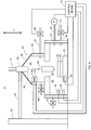
- FIG. 1 schematically shows a structure of a specimen preparation apparatus 10 according to the first embodiment of the present disclosure.
- the specimen preparation apparatus 10 is an apparatus which prepares a specimen to be observed by a microscope.
- the specimen preparation apparatus 10 is, for example, a specimen cooling and drying apparatus, and prepares a microparticle specimen by cooling a liquid drop having a solution in which microparticles are dispersed in a solvent as an undiluted solution (hereinafter, referred to as "microparticle dispersed liquid drop") and drying the solvent of the liquid drop.
- the microparticle to be observed is a microparticle, for example, having a particle size (for example, a length of a shortest portion of the microparticle) in a range of 1 nm ⁇ 100 ⁇ m. Alternatively, particles having particle sizes outside of this range may be used as the particle to be observed.
- a volume of the microparticle dispersed liquid drop is, for example, about 1 pL (pico-liter). Alternatively, the volume of the microparticle dispersed liquid drop may be other than 1 pL.
- the solvent of the liquid drop for example, water, ethanol, methanol, or the like is used. Alternatively solvents other than these may be used.
- the microscope is, for example, a microscope which uses an electron beam, an ion beam, or the like, and is, for example, a transmission electron microscope (TEM), a scanning electron microscope (SEM), a scanning transmission electron microscope (STEM), an atomic force microscope (AFM), a scanning probe microscope (SPM), a scanning tunnel microscope (STM), a helium ion microscope (HIM), an optical microscope which uses light and laser, or the like.
- TEM transmission electron microscope
- SEM scanning electron microscope
- STEM scanning transmission electron microscope
- STEM scanning transmission electron microscope
- STEM scanning transmission electron microscope
- AFM atomic force microscope
- SPM scanning probe microscope
- STM scanning tunnel microscope
- HIM helium ion microscope
- the specimen preparation apparatus 10 generally includes a lower-side structure 12, an upper-side structure 14 provided above the lower-side structure 12, and a gate valve 16.
- the lower-side structure 12 is a member in the inside of which a specimen chamber 18 is formed.
- the lower-side structure 12 is, for example, a vacuum chamber, and the specimen chamber 18 is a space having airtightness.
- the upper-side structure 14 is a member in the inside of which a nozzle chamber 20 is formed.
- the nozzle chamber 20 is formed above the specimen chamber 18.
- the nozzle chamber 20 is, for example, a simple space, and is not a completely airtight chamber.
- the gate valve 16 is a member which performs an open and close operation, is provided between the lower-side structure 12 and the upper-side structure 14, and is a member which separates the specimen chamber 18 and the nozzle chamber 20 (a movable separation member).
- the gate valve 16 In a state where the gate valve 16 is closed, the specimen chamber 18 and the nozzle chamber 20 are separated by the gate valve 16, and in a state where the gate valve 16 is open, the specimen chamber 18 and the nozzle chamber 20 are in communication with each other (connected to each other).
- the gate valve 16 is closed, and thus, the specimen chamber 18 and the nozzle chamber 20 are separated.
- the specimen chamber 18 is in a tightly sealed state.
- a specimen holder base 22 is provided. On the specimen holder base 22, a specimen holder 24 onto which the microparticle dispersed liquid drop is dropped is placed. On the specimen holder 24, for example, a plurality of pores, fine channels, or the like are in a regular arrangement such as a grid shape, an array shape, or a honeycomb shape, or an electron microscope grid mesh or a grid mesh with a support membrane is mounted on the specimen holder 24. The microparticle dispersed liquid drop is dropped onto individual pores or fine channels. Alternatively, the specimen holder 24 may be a member having another shape such as a substrate.
- the specimen holder base 22 and the specimen holder 24 are formed from, for example, a material such as a metal such as aluminum, copper, or the like, fine ceramics, or the like, and a part of the specimen holder 24 may be formed by a thin film of an organic substance. In other words, the specimen holder base 22 and the specimen holder 24 may be formed by any material, so long as the material does not obstruct heat conduction.
- the specimen holder base 22 is provided on a specimen cooling member 26.
- the specimen cooling member 26 is a member for cooling the microparticle dispersed liquid drop dropped onto the specimen holder 24, and cools the microparticle dispersed liquid drop using, for example, a Peltier element.
- the microparticle dispersed liquid drop is cooled to, for example, a temperature of about -40°C ⁇ -20°C by the specimen cooling member 26. Alternatively, the microparticle dispersed liquid drop may be cooled by other methods.
- the specimen holder base 22, the specimen holder 24, and the specimen cooling member 26 collectively form, for example, a "specimen base.”
- An opening 28 is formed at an upper part of the lower-side structure 12. In the state where the gate valve 16 is open, the specimen chamber 18 and the nozzle chamber 20 are in communication with each other through the opening 28.
- a transparent window 30 (for example, a glass window) may be provided on a side surface of the lower-side structure 12.
- a camera 32 is placed at an outer side of the lower-side structure 12, and the camera 32 images the inside of the specimen chamber 18 through the window 30.
- the microparticle dispersed liquid drop dropped onto the specimen holder 24 is imaged by the camera 32, so that an operator can observe the state of the microparticle dispersed liquid drop and the specimen holder 24, or the like. For example, the operator can check whether or not there is an occurrence of the dew condensation.
- the lower-side structure 12 is formed from, for example, a metal such as aluminum, copper, or the like. Alternatively, the lower-side structure 12 may be formed from other materials.
- At least a tip opening 36 of a nozzle 34 is present in the nozzle chamber 20.
- the tip opening 36 is placed in the nozzle chamber 20.
- the entirety of the nozzle 34 may be placed in the nozzle chamber 20.
- the nozzle 34 is, for example, an inkjet nozzle.
- a solution in which the microparticle is dispersed is supplied from a solution supply system (not shown) to the nozzle 34, and the nozzle 34 ejects the microparticle dispersed liquid drop from the tip opening 36.
- the nozzle 34 is movable at least in the up-and-down direction (Z direction) by a transport mechanism 40 to be described later.
- the upper-side structure 14 includes a cover member 38 serving as a deformation member which deforms with a movement of the nozzle 34.
- the cover member 38 is, for example, a bag-shaped member which surrounds and seals from an opening edge of the gate valve 16 to a periphery of the nozzle 34. A space surrounded by the cover member 38 corresponds to the nozzle chamber 20.
- the cover member 38 may be a member having a shape other than the bag shape; for example, the cover member 38 may be a bellows-shaped member which deforms with the movement of the nozzle 34.
- the cover member 38 is formed from, for example, a material having elasticity (for example, a resin).
- the specimen preparation apparatus 10 also comprises the transport mechanism 40.
- the transport mechanism 40 is a mechanism which transports the nozzle 34 in at least the up-and-down direction (Z direction).
- the transport mechanism 40 transports the nozzle 34 between the lower-side structure 12 and the upper-side structure 14 by transporting, for example, the nozzle 34 in the up-and-down direction.
- the transport mechanism 40 may have functions to transport the nozzle 34 in a plurality of directions orthogonal to the up-and-down direction (Z direction) (for example, a left-and-right direction (X direction), and a front-and-rear direction (Y direction)).
- the X direction, the Y direction, and the Z direction are directions orthogonal to each other.
- a camera 42 is provided above the nozzle 34. With the camera 42, it becomes possible to image the nozzle chamber 20 from above the chamber, and the specimen chamber 18 can be imaged from above the chamber in the state where the gate valve 16 is open.
- the specimen preparation apparatus 10 may be placed on a platform truck 44 such as a storage rack or the like.
- a platform truck 44 such as a storage rack or the like.
- the platform truck 44 for example, there may be stored a control device which controls the ejection operation of the microparticle dispersed liquid drop by the nozzle 34, the transport operation of the nozzle 34 by the transport mechanism 40, or the like.
- the specimen preparation apparatus 10 may be placed on the floor or the like, and not on the platform truck 44.
- the gate valve 16 is opened so that the specimen chamber 18 and the nozzle chamber 20 are connected to each other, and, in this state, the nozzle 34 is transported from the nozzle chamber 20 into the specimen chamber 18 by the transport mechanism 40.
- the cover member 38 is deformed (for example, folded).
- the nozzle 34 is transported until the tip opening 36 of the nozzle 34 is placed near the specimen holder 24, and, in this state, the nozzle 34 ejects the microparticle dispersed liquid drop from the tip opening 36 onto the specimen holder 24. With this process, the microparticle dispersed liquid drop is dropped onto the specimen holder 24.
- the microparticle dispersed liquid drop is ejected from the nozzle 34, to drop a plurality of the microparticle dispersed liquid drops onto the specimen holder 24.
- the microparticle dispersed liquid drops are dropped into the plurality of pores and fine channels formed in the grid shape.
- the microparticle dispersed liquid drop dropped onto the specimen holder 24 is frozen by the specimen cooling member 26.
- the nozzle 34 is transported from inside of the specimen chamber 18 into the nozzle chamber 20 by the transport mechanism 40. After the transport is completed, the gate valve 16 is closed. In this state, the pressure inside the specimen chamber 18 is reduced by a vacuum pump, and the inside of the specimen chamber 18 is set in a vacuum state. With this process, vacuum-drying is executed.
- the solvent of the microparticle dispersed liquid drop is evaporated (frozen solvent is sublimated), and the microparticle remains in the specimen holder 24. The remaining microparticle is used as the specimen for the microscope. Alternatively, depending on the observation condition by the microscope, the solvent may also remain.
- FIG. 3 shows a more detailed structure of the specimen preparation apparatus 10, and pipes or the like are shown in addition to the structure of the specimen preparation apparatus 10 shown in FIG. 1 .
- the specimen preparation apparatus 10 comprises the lower-side structure 12, the upper-side structure 14, the gate valve 16, and the nozzle 34.
- the specimen chamber 18 is formed, and the specimen cooling member 26 is placed in the specimen chamber 18.
- the specimen holder base 22 is placed on the specimen cooling member 26, and the specimen holder 24 is placed on the specimen holder base 22.
- the upper-side structure 14 includes the cover member 38, and the nozzle chamber 20 is formed in the upper-side structure 14. In the nozzle chamber 20, at least the tip opening 36 of the nozzle 34 is present.
- the gate valve 16 is closed, and thus, the specimen chamber 18 and the nozzle chamber 20 are separated.
- the specimen chamber 18 and the nozzle chamber 20 are in communication with each other (connected to each other) through the opening 28 of the lower-side structure 12.
- the nozzle 34 is transported in the X direction, the Y direction, and the Z direction by the transport mechanism 40.
- the window 30 may be provided on the lower-side structure 12 and the inside of the specimen chamber 18 may be imaged by the camera 32, as shown in FIG. 1 . Further, the inside of the specimen chamber 18 may be imaged from above the chamber by the camera 42.
- a temperature sensor 46 is provided on the specimen cooling member 26.
- the temperature sensor 46 measures a temperature of the specimen cooling member 26.
- a measurement value of the temperature sensor 46 (temperature data) is output to a control device 74 to be described later.
- the temperature of the specimen cooling member 26 is controlled by reference to the measurement value of the temperature sensor 46.
- a vacuum pipe 48 is provided in the lower-side structure 12. One end of the vacuum pipe 48 is placed in the specimen chamber 18, and the other end is connected to a vacuum pump P. In the vacuum-drying, the pressure in the specimen chamber 18 is reduced by the vacuum pump P. For example, the pressure after the pressure reduction is about 20 Pa to 0.1 Pa.
- the numerical values described herein are merely exemplary, and the degree of pressure reduction may be adjusted according to the conditions of the specimen preparation.
- a drying gas pipe 50 is provided in the lower-side structure 12. One end of the drying gas pipe 50 is placed in the specimen chamber 18, and the other end is connected to a drying gas supply system (not shown). The drying gas supplied from the drying gas supply system is supplied to the specimen chamber 18 through the drying gas pipe 50.
- a gas having a lower dew-point temperature than a reaching temperature of the specimen base for example, nitrogen gas, inert gas such as argon gas, dry air, or the like, may be used.
- An electromagnetic valve 52 is provided on the drying gas pipe 50, and the amount of supply of the drying gas into the specimen chamber 18 can be adjusted by controlling open and close states of the electromagnetic valve 52. The control to open and close the electromagnetic valve 52 is achieved by the control device 74 to be described later.
- a relief valve 54 is provided on the lower-side structure 12.
- a preset pressure a preset pressure (a first setting pressure)
- the relief valve 54 is opened, and the gas in the specimen chamber 18 is discharged to the outside of the specimen chamber 18.
- the relief valve 54 is closed.
- a temperature and humidity sensor 56 and a pressure sensor 58 may be provided in the specimen chamber 18.
- the temperature and humidity sensor 56 and the pressure sensor 58 are attached on an inner side surface of the lower-side structure 12 in the specimen chamber 18.
- the temperature and humidity sensor 56 measures a temperature and a humidity in the specimen chamber 18, and the pressure sensor 58 measures a pressure in the specimen chamber 18.
- Measurement values of the temperature and humidity sensor 56 (temperature data and humidity data), and a measurement value of the pressure sensor 58 (pressure data) are output to the control device 74 to be described later.
- the amount of the drying gas to be supplied into the specimen chamber 18 may be controlled based on the measurement values of the temperature and humidity sensor 56 and the measurement value of the pressure sensor 58.
- the upper-side structure 14 includes a hard frame 60 in addition to the cover member 38.
- the frame 60 is provided almost vertically to surround the opening 28 and the opening of the gate valve 16 at a periphery of the gate valve 16.
- the cover member 38 surrounds and seals from the opening edge at an upper-side of the frame 60 to the periphery of the nozzle 34.
- a space surrounded by the cover member 38 and the frame 60 corresponds to the nozzle chamber 20.
- the frame 60 may be omitted.
- the cover member 38 surrounds and seals from the opening edge of the gate valve 16 to the periphery of the nozzle 34, and a space surrounded by the cover member 38 corresponds to the nozzle chamber 20.
- a drying gas pipe 62 is placed on the frame 60. One end of the drying gas pipe 62 is placed in the nozzle chamber 20, and the other end is connected to the drying gas supply system (not shown). The drying gas supplied from the drying gas supply system is supplied into the nozzle chamber 20 through the drying gas pipe 62.
- An electromagnetic valve 64 is provided on the drying gas pipe 62, and the amount of supply of the drying gas into the nozzle chamber 20 can be adjusted by controlling the open and close states of the electromagnetic valve 64. The control of the opening and closing of the electromagnetic valve 64 is executed by the control device 74 to be described later.
- a relief valve 66 is provided on the frame 60.
- a pressure in the nozzle chamber 20 becomes greater than or equal to a preset pressure (a second setting pressure)
- the relief valve 66 is opened, and the gas in the nozzle chamber 20 is discharged to the outside of the nozzle chamber 20.
- the pressure in the nozzle chamber 20 is lower than the second setting pressure
- the relief valve 66 is closed.
- the second setting pressure for the relief valve 66 provided in the nozzle chamber 20 is lower than the first setting pressure for the relief valve 54 provided in the specimen chamber 18 (first setting pressure > second setting pressure).
- a temperature and humidity sensor 68 and a pressure sensor 70 may be provided in the nozzle chamber 20.
- the temperature and humidity sensor 68 and the pressure sensor 70 are attached on an inner side surface of the frame 60 in the nozzle chamber 20.
- the temperature and humidity sensor 68 measures a temperature and a humidity in the nozzle chamber 20, and the pressure sensor 70 measures a pressure in the nozzle chamber 20.
- Measurement values of the temperature and humidity sensor 68 (temperature data and humidity data), and a measurement value of the pressure sensor 70 (pressure data) are output to the control device 74 to be described later.
- the amount of the drying gas to be supplied into the nozzle chamber 20 may be controlled based on the measurement values of the temperature and humidity sensor 68 and the measurement value of the pressure sensor 70.
- a specimen supply pipe 72 is connected to the nozzle 34.
- a solution in which a microparticle is dispersed in a solvent is supplied from a specimen supply system (not shown) to the nozzle 34 through the specimen supply pipe 72.
- the nozzle 34 receives the solution supplied from the specimen supply system, and ejects the microparticle dispersed liquid drop.
- the ejection operation of the microparticle dispersed liquid drop is controlled by the control device 74 to be described later.
- the control device 74 is a device which controls the opening and closing of the gate valve 16, the cooling operation by the specimen cooling member 26, the ejection operation of the liquid drop by the nozzle 34, the transport operation by the transport mechanism 40, the operation of the pump P, the opening and closing of the electromagnetic valves 52 and 64, or the like.
- the control device 74 controls the operations of respective units according to the stages of the specimen preparation, for example.
- the control device 74 may control the opening and closing of the electromagnetic valves 52 and 64 based on the measurement values of the temperature and humidity sensors 56 and 68, and the measurement values of the pressure sensors 58 and 70.
- the control device 74 comprises, for example, a processor such as a CPU and a storage device which stores a program (such as, for example, a memory, a hard disk drive, or the like), and the control by the control device 74 is realized by the processor reading and executing the program.
- the control device 74 may be formed by hardware circuits.
- the control device 74 controls the gas pressure, for example, such that the pressure in the specimen chamber 18 (gas pressure) is higher than the pressure in the nozzle chamber 20 (gas pressure). For example, the control device 74 controls the amount of drying gas supplied into the specimen chamber 18 such that the gas pressure in the specimen chamber 18 is higher than the gas pressure in the nozzle chamber 20. More specifically, the control device 74 controls the amount of drying gas such that the gas pressure in the specimen chamber 18 is higher than the gas pressure in the nozzle chamber 20 in a state where the specimen holder base 22 and the specimen holder 24 are cooled by the specimen cooling member 26, and before the gate valve 16 is opened.
- control device 74 reduces the pressure in the specimen chamber 18 by the vacuum pump P (sets a vacuum state) in the state where the gate valve 16 is closed, and then cools the specimen holder base 22 and the specimen holder 24 by the specimen cooling member 26.
- the control device 74 introduces the drying gas into the specimen chamber 18 in this state.
- the control device 74 opens the gate valve 16 after the gas pressure in the specimen chamber 18 becomes higher than the gas pressure in the nozzle chamber 20, and transports the nozzle 34 from the nozzle chamber 20 to the specimen chamber 18.
- the control device 74 may supply the drying gas to the specimen chamber 18 after the gate valve 16 is opened, and may thus maintain the relationship of the gas pressures between the specimen chamber 18 and the nozzle chamber 20.
- the gate valve 16 is closed, as shown in FIG. 3 .
- FIG. 4 shows the nozzle 34 transported into the specimen chamber 18 with a solid line.
- the cover member 38 is deformed. The nozzle 34 is transported until the tip opening 36 of the nozzle 34 is placed near the specimen holder 24.
- the nozzle 34 ejects the microparticle dispersed liquid drop from the tip opening 36 onto the specimen holder 24.
- the microparticle dispersed liquid drop is dropped onto the specimen holder 24.
- the microparticle dispersed liquid drop may be ejected from the nozzle 34 while the nozzle 34 is moved in the X and Y directions by the transport mechanism 40, so that a plurality of microparticle dispersed liquid drop are dropped onto the specimen holder 24.
- the microparticle dispersed liquid drop is dropped from the nozzle 34 onto the specimen holder 24, a state is maintained in which the gas pressure in the specimen chamber 18 is higher than the gas pressure in the nozzle chamber 20.
- this configuration it becomes possible to prevent or suppress intrusion of warm air from the nozzle chamber 20 into the specimen chamber 18, and, as a result, occurrence of the dew condensation at the specimen holder base 22, the specimen holder 24, and the specimen cooling member 26 can be prevented. Because of this, it becomes possible to prevent contamination of the microparticle specimen caused by the dew condensation.
- the inside of the specimen chamber 18 may be imaged by the camera 32, and the operator may observe the inside of the specimen chamber 18 with the image obtained by the camera 32.
- the operator may command to increase the amount of supply of the drying gas into the specimen chamber 18.
- the control device 74 in response to the command, increases the amount of supply of the drying gas into the specimen chamber 18. With this process, it becomes possible to prevent occurrence of the dew condensation at the periphery of the specimen cooling member 26.
- control device 74 may control the amount of supply of the drying gas into the specimen chamber 18 (that is, the degree of opening of the electromagnetic valve 52) based on the measurement data (temperature and humidity) obtained by the temperature and humidity sensor 56. For example, the control device 74 may control the amount of supply of the drying gas into the specimen chamber 18 so that the humidity in the specimen chamber 18 (for example, relative humidity) is lower than or equal to a preset target humidity.
- control device 74 may control the amount of supply of the drying gas into the specimen chamber 18 such that the relative humidity (amount of water vapor A of the ambience in the specimen chamber 18/saturation amount of water vapor C in the ambience) is lower than or equal to a target relative humidity (saturation amount of water vapor B in the specimen cooling member 26/saturation amount of water vapor C in the ambience).
- FIG. 5 shows a structure of the specimen preparation apparatus 10A according to the second embodiment of the present disclosure.
- the specimen preparation apparatus 10A includes the structures of the specimen preparation apparatus 10 according to the first embodiment shown in FIG. 3 , and further comprises a cooling member 76.
- the cooling member 76 is placed, for example, in the nozzle chamber 20 and on an inner side surface of the frame 60.
- the cooling member 76 is a member for reducing the temperature in the nozzle chamber 20, and reduces the temperature in the nozzle chamber 20 using, for example, a Peltier element. Alternatively, the temperature in the nozzle chamber 20 may be reduced using other methods.
- the control device 74 further controls the cooling operation by the cooling member 76.
- the inside of the nozzle chamber 20 is cooled by the cooling member 76.
- the gas pressure in the nozzle chamber 20 is reduced. With this process, it becomes possible to prevent or suppress a state that the gas pressure in the nozzle chamber 20 is higher than the gas pressure in the specimen chamber 18.
- the second embodiment also, similar to the first embodiment, there is maintained a state in which the gas pressure in the specimen chamber 18 is higher than the gas pressure in the nozzle chamber 20, and the intrusion of the air from the nozzle chamber 20 into the specimen chamber 18 can be prevented or suppressed. Because of this, occurrence of dew condensation at the specimen holder base 22, the specimen holder 24, and the specimen cooling member 26 can be prevented, and contamination of the microparticle specimen can be prevented.
- FIG. 6 shows a structure of the specimen preparation apparatus 10B according to the third embodiment of the present disclosure.
- the specimen preparation apparatus 10B includes the structures of the specimen preparation apparatus 10 of the first embodiment shown in FIG. 3 , and further comprises a cover support member 78.
- the cover support member 78 is placed on a surface at an outer side (outer side of the nozzle chamber 20) of the cover member 38, and, for example, a member such as a string or a rubber member having elasticity is attached.
- a tension force thereof is applied to the cover member 38, and the cover member 38 is pulled in the outer direction of the nozzle chamber 20.
- An operation of the specimen preparation apparatus 10B in the specimen preparation; that is, a specimen preparation method according to the third embodiment, is identical to the operation of the specimen preparation apparatus 10 of the first embodiment; that is, the specimen preparation method of the first embodiment, and thus will not be described again.
- the specimen preparation apparatus 10B of the third embodiment may comprise the cooling member 76 similar to the specimen preparation apparatus 10A of the second embodiment.
- the operation of the specimen preparation apparatus 10B of the third embodiment that is, the specimen preparation method of the third embodiment, is identical to the operation of the specimen preparation apparatus 10A of the second embodiment; that is, the specimen preparation method of the second embodiment.
- the operation in this case also will not be described.
- the frame 60 may be omitted in the specimen preparation apparatus 10B.
- the cover member 38 is pulled in the outer direction of the nozzle chamber 20 by the tension force through the cover support member 78, the entry and dragging of the cover member 38 into the specimen chamber 18 can be prevented.
Landscapes
- Life Sciences & Earth Sciences (AREA)
- Health & Medical Sciences (AREA)
- General Health & Medical Sciences (AREA)
- Chemical & Material Sciences (AREA)
- Analytical Chemistry (AREA)
- Biochemistry (AREA)
- Physics & Mathematics (AREA)
- General Physics & Mathematics (AREA)
- Immunology (AREA)
- Pathology (AREA)
- Engineering & Computer Science (AREA)
- Biomedical Technology (AREA)
- Molecular Biology (AREA)
- Sampling And Sample Adjustment (AREA)
- Drying Of Solid Materials (AREA)
Abstract
Description
- The present disclosure relates to a technique for preparing a specimen for a microscope.
- There are some cases where a microparticle specimen to be observed by a microscope such as an electron microscope is prepared from a liquid drop having a solution in which the microparticles are dispersed in a solvent as an undiluted solution (hereinafter, referred to as "microparticle dispersed liquid drop"). For example, there is known a technique in which the microparticle dispersed liquid drop is dropped onto a cooled specimen base and is cooled (for example, the liquid drop is solidified), and the solvent of the liquid drop is dried in this state to prepare the microparticle specimen (as disclosed in, for example,
JP 2015-141083 A - Depending on the environment, dew condensation may occur on the specimen base or the like during the preparation process of the specimen, and the specimen may be contaminated by a contaminating substance in water produced by the dew condensation.
- An advantage of the present disclosure lies in prevention of occurrence of the dew condensation on the specimen base or the like in cases where the specimen is prepared by drying the solvent of the liquid drop in which the specimen is dispersed.
- According to one aspect of the present disclosure, there is provided a specimen preparation apparatus comprising: a lower-side structure that forms a specimen chamber in which a specimen base is provided; an upper-side structure that forms a nozzle chamber above the specimen chamber; a gate valve that separates the specimen chamber and the nozzle chamber; and a controller that controls a gas pressure in the specimen chamber, wherein at least a nozzle tip opening of a nozzle that ejects a specimen is present in the nozzle chamber, and the controller maintains a relationship of gas pressures such that a gas pressure in the specimen chamber is higher than a gas pressure in the nozzle chamber when the lower-side structure and the upper-side structure are in communication with each other.
- According to the above-described structure, because the gas pressure in the specimen chamber is higher than the gas pressure in the nozzle chamber, intrusion of air from the nozzle chamber into the specimen chamber can be prevented or suppressed. With such a configuration, even when the temperature in the specimen chamber is reduced by cooling the inside of the specimen chamber, occurrence of dew condensation at the specimen base or the like can be prevented. When the specimen is prepared, the gate valve is opened, and the nozzle is transported from the nozzle chamber into the specimen chamber. On the specimen base, for example, a specimen holder is placed, and a liquid drop is ejected from the nozzle tip opening to the specimen holder. In the liquid drop, the specimen (for example, a microparticle) is dispersed. For example, a pressure of the specimen chamber is reduced by a vacuum pump so that the solvent of the liquid drop is dried and the specimen (for example, a microparticle specimen) remains on the specimen holder.
- According to another aspect of the present disclosure, a period in which the lower-side structure and the upper-side structure are in communication with each other may be a period included in a process of dropping the specimen onto the specimen base.
- According to another aspect of the present disclosure, the controller may control supply of a drying gas into the specimen chamber such that the gas pressure in the specimen chamber is higher than the gas pressure in the nozzle chamber.
- According to another aspect of the present disclosure, the controller may maintain the relationship of the gas pressures between the specimen chamber and the nozzle chamber by supplying the drying gas into the specimen chamber after the gate valve is opened. With this configuration, even when the gate valve is opened and the specimen chamber and the nozzle chamber are connected to each other, the gas pressure in the specimen chamber can be maintained at a higher pressure than the gas pressure in the nozzle chamber.
- According to another aspect of the present disclosure, the specimen preparation apparatus may further comprise a cooler that cools the specimen base, and the controller may control the gas pressures such that the gas pressure in the specimen chamber is higher than the gas pressure in the nozzle chamber after the specimen base is cooled by the cooler and before the gate valve is opened.
- According to another aspect of the present disclosure, the specimen preparation apparatus may further comprise a vacuum device that reduces a pressure in the specimen chamber, and the controller may open the gate valve after reducing the pressure in the specimen chamber by the vacuum device, cooling the specimen base by the cooler, supplying the drying gas into the specimen chamber, and then forming the relationship of the gas pressures between the specimen chamber and the nozzle chamber, in a state where the gate valve is closed.
- According to another aspect of the present disclosure, the specimen preparation apparatus may further comprise a transport mechanism that transports the nozzle between the upper-side structure and the lower-side structure, and the upper-side structure may comprise a deformation member that deforms with a movement of the nozzle.
- According to another aspect of the present disclosure, the specimen preparation apparatus may further comprise a hard frame that is placed to surround an opening of the gate valve at a periphery of the gate valve, and the deformation member may be a bag-shaped member which seals from an opening edge of the frame to a periphery of the nozzle.
- According to the above-described structure, with the frame, it becomes possible to prevent entry or dragging of the deformation member into the specimen chamber. For example, the nozzle chamber is formed by the deformation member.
- According to another aspect of the present disclosure, the controller may further control a process of dropping the specimen onto the specimen base by the nozzle, and a process of executing vacuum-drying by reducing a pressure in the specimen chamber after the specimen is dropped onto the specimen base.
- According to the present disclosure, it becomes possible to prevent occurrence of the dew condensation at the specimen base or the like in a case where the specimen is prepared by drying the solvent of the liquid drop in which the specimen is dispersed.
- Embodiment(s) of the present disclosure will be described by reference to the following figures, wherein:
-
FIG. 1 is a diagram showing a specimen preparation apparatus according to a first embodiment of the present disclosure; -
FIG. 2 is a diagram showing the specimen preparation apparatus according to the first embodiment of the present disclosure; -
FIG. 3 is a diagram showing the specimen preparation apparatus according to the first embodiment of the present disclosure; -
FIG. 4 is a diagram showing the specimen preparation apparatus according to the first embodiment of the present disclosure; -
FIG. 5 is a diagram showing a specimen preparation apparatus according to a second embodiment of the present disclosure; and -
FIG. 6 is a diagram showing a specimen preparation apparatus according to a third embodiment of the present disclosure. - A specimen preparation apparatus according to a first embodiment of the present disclosure will now be described.
FIG. 1 schematically shows a structure of aspecimen preparation apparatus 10 according to the first embodiment of the present disclosure. Thespecimen preparation apparatus 10 is an apparatus which prepares a specimen to be observed by a microscope. Thespecimen preparation apparatus 10 is, for example, a specimen cooling and drying apparatus, and prepares a microparticle specimen by cooling a liquid drop having a solution in which microparticles are dispersed in a solvent as an undiluted solution (hereinafter, referred to as "microparticle dispersed liquid drop") and drying the solvent of the liquid drop. - The microparticle to be observed is a microparticle, for example, having a particle size (for example, a length of a shortest portion of the microparticle) in a range of 1 nm ~ 100 µm. Alternatively, particles having particle sizes outside of this range may be used as the particle to be observed. A volume of the microparticle dispersed liquid drop is, for example, about 1 pL (pico-liter). Alternatively, the volume of the microparticle dispersed liquid drop may be other than 1 pL. As the solvent of the liquid drop, for example, water, ethanol, methanol, or the like is used. Alternatively solvents other than these may be used.
- The microscope is, for example, a microscope which uses an electron beam, an ion beam, or the like, and is, for example, a transmission electron microscope (TEM), a scanning electron microscope (SEM), a scanning transmission electron microscope (STEM), an atomic force microscope (AFM), a scanning probe microscope (SPM), a scanning tunnel microscope (STM), a helium ion microscope (HIM), an optical microscope which uses light and laser, or the like.
- The
specimen preparation apparatus 10 generally includes a lower-side structure 12, an upper-side structure 14 provided above the lower-side structure 12, and agate valve 16. The lower-side structure 12 is a member in the inside of which aspecimen chamber 18 is formed. The lower-side structure 12 is, for example, a vacuum chamber, and thespecimen chamber 18 is a space having airtightness. The upper-side structure 14 is a member in the inside of which anozzle chamber 20 is formed. Thenozzle chamber 20 is formed above thespecimen chamber 18. Thenozzle chamber 20 is, for example, a simple space, and is not a completely airtight chamber. Thegate valve 16 is a member which performs an open and close operation, is provided between the lower-side structure 12 and the upper-side structure 14, and is a member which separates thespecimen chamber 18 and the nozzle chamber 20 (a movable separation member). In a state where thegate valve 16 is closed, thespecimen chamber 18 and thenozzle chamber 20 are separated by thegate valve 16, and in a state where thegate valve 16 is open, thespecimen chamber 18 and thenozzle chamber 20 are in communication with each other (connected to each other). In the example configuration ofFIG. 1 , thegate valve 16 is closed, and thus, thespecimen chamber 18 and thenozzle chamber 20 are separated. In the state where thegate valve 16 is closed, thespecimen chamber 18 is in a tightly sealed state. - In the
specimen chamber 18, aspecimen holder base 22 is provided. On thespecimen holder base 22, aspecimen holder 24 onto which the microparticle dispersed liquid drop is dropped is placed. On thespecimen holder 24, for example, a plurality of pores, fine channels, or the like are in a regular arrangement such as a grid shape, an array shape, or a honeycomb shape, or an electron microscope grid mesh or a grid mesh with a support membrane is mounted on thespecimen holder 24. The microparticle dispersed liquid drop is dropped onto individual pores or fine channels. Alternatively, thespecimen holder 24 may be a member having another shape such as a substrate. Thespecimen holder base 22 and thespecimen holder 24 are formed from, for example, a material such as a metal such as aluminum, copper, or the like, fine ceramics, or the like, and a part of thespecimen holder 24 may be formed by a thin film of an organic substance. In other words, thespecimen holder base 22 and thespecimen holder 24 may be formed by any material, so long as the material does not obstruct heat conduction. Thespecimen holder base 22 is provided on aspecimen cooling member 26. Thespecimen cooling member 26 is a member for cooling the microparticle dispersed liquid drop dropped onto thespecimen holder 24, and cools the microparticle dispersed liquid drop using, for example, a Peltier element. The microparticle dispersed liquid drop is cooled to, for example, a temperature of about -40°C ∼ -20°C by thespecimen cooling member 26. Alternatively, the microparticle dispersed liquid drop may be cooled by other methods. Thespecimen holder base 22, thespecimen holder 24, and thespecimen cooling member 26 collectively form, for example, a "specimen base." - An
opening 28 is formed at an upper part of the lower-side structure 12. In the state where thegate valve 16 is open, thespecimen chamber 18 and thenozzle chamber 20 are in communication with each other through theopening 28. - In addition, a transparent window 30 (for example, a glass window) may be provided on a side surface of the lower-
side structure 12. Acamera 32 is placed at an outer side of the lower-side structure 12, and thecamera 32 images the inside of thespecimen chamber 18 through thewindow 30. For example, the microparticle dispersed liquid drop dropped onto thespecimen holder 24 is imaged by thecamera 32, so that an operator can observe the state of the microparticle dispersed liquid drop and thespecimen holder 24, or the like. For example, the operator can check whether or not there is an occurrence of the dew condensation. - The lower-
side structure 12 is formed from, for example, a metal such as aluminum, copper, or the like. Alternatively, the lower-side structure 12 may be formed from other materials. - At least a
tip opening 36 of anozzle 34 is present in thenozzle chamber 20. In other words, thetip opening 36 is placed in thenozzle chamber 20. Alternatively, the entirety of thenozzle 34 may be placed in thenozzle chamber 20. Thenozzle 34 is, for example, an inkjet nozzle. A solution in which the microparticle is dispersed is supplied from a solution supply system (not shown) to thenozzle 34, and thenozzle 34 ejects the microparticle dispersed liquid drop from thetip opening 36. Thenozzle 34 is movable at least in the up-and-down direction (Z direction) by atransport mechanism 40 to be described later. - The upper-
side structure 14 includes acover member 38 serving as a deformation member which deforms with a movement of thenozzle 34. Thecover member 38 is, for example, a bag-shaped member which surrounds and seals from an opening edge of thegate valve 16 to a periphery of thenozzle 34. A space surrounded by thecover member 38 corresponds to thenozzle chamber 20. Alternatively, thecover member 38 may be a member having a shape other than the bag shape; for example, thecover member 38 may be a bellows-shaped member which deforms with the movement of thenozzle 34. Thecover member 38 is formed from, for example, a material having elasticity (for example, a resin). - The
specimen preparation apparatus 10 also comprises thetransport mechanism 40. Thetransport mechanism 40 is a mechanism which transports thenozzle 34 in at least the up-and-down direction (Z direction). Thetransport mechanism 40 transports thenozzle 34 between the lower-side structure 12 and the upper-side structure 14 by transporting, for example, thenozzle 34 in the up-and-down direction. Alternatively, thetransport mechanism 40 may have functions to transport thenozzle 34 in a plurality of directions orthogonal to the up-and-down direction (Z direction) (for example, a left-and-right direction (X direction), and a front-and-rear direction (Y direction)). The X direction, the Y direction, and the Z direction are directions orthogonal to each other. - A
camera 42 is provided above thenozzle 34. With thecamera 42, it becomes possible to image thenozzle chamber 20 from above the chamber, and thespecimen chamber 18 can be imaged from above the chamber in the state where thegate valve 16 is open. - The
specimen preparation apparatus 10 may be placed on aplatform truck 44 such as a storage rack or the like. In theplatform truck 44, for example, there may be stored a control device which controls the ejection operation of the microparticle dispersed liquid drop by thenozzle 34, the transport operation of thenozzle 34 by thetransport mechanism 40, or the like. Alternatively, thespecimen preparation apparatus 10 may be placed on the floor or the like, and not on theplatform truck 44. - When the microparticle dispersed liquid drop is dropped onto the
specimen holder 24, as shown inFIG. 2 , thegate valve 16 is opened so that thespecimen chamber 18 and thenozzle chamber 20 are connected to each other, and, in this state, thenozzle 34 is transported from thenozzle chamber 20 into thespecimen chamber 18 by thetransport mechanism 40. In this process, with the movement of thenozzle 34, thecover member 38 is deformed (for example, folded). Thenozzle 34 is transported until the tip opening 36 of thenozzle 34 is placed near thespecimen holder 24, and, in this state, thenozzle 34 ejects the microparticle dispersed liquid drop from thetip opening 36 onto thespecimen holder 24. With this process, the microparticle dispersed liquid drop is dropped onto thespecimen holder 24. For example, while thenozzle 34 is moved in the X and Y directions by thetransport mechanism 40, the microparticle dispersed liquid drop is ejected from thenozzle 34, to drop a plurality of the microparticle dispersed liquid drops onto thespecimen holder 24. For example, the microparticle dispersed liquid drops are dropped into the plurality of pores and fine channels formed in the grid shape. The microparticle dispersed liquid drop dropped onto thespecimen holder 24 is frozen by thespecimen cooling member 26. - After the dropping of the microparticle dispersed liquid crop is completed, the
nozzle 34 is transported from inside of thespecimen chamber 18 into thenozzle chamber 20 by thetransport mechanism 40. After the transport is completed, thegate valve 16 is closed. In this state, the pressure inside thespecimen chamber 18 is reduced by a vacuum pump, and the inside of thespecimen chamber 18 is set in a vacuum state. With this process, vacuum-drying is executed. The solvent of the microparticle dispersed liquid drop is evaporated (frozen solvent is sublimated), and the microparticle remains in thespecimen holder 24. The remaining microparticle is used as the specimen for the microscope. Alternatively, depending on the observation condition by the microscope, the solvent may also remain. - The structure of the
specimen preparation apparatus 10 will now be described in further detail with reference toFIG. 3. FIG. 3 shows a more detailed structure of thespecimen preparation apparatus 10, and pipes or the like are shown in addition to the structure of thespecimen preparation apparatus 10 shown inFIG. 1 . - Similar to the structure shown in
FIG. 1 , thespecimen preparation apparatus 10 comprises the lower-side structure 12, the upper-side structure 14, thegate valve 16, and thenozzle 34. In the lower-side structure 12, thespecimen chamber 18 is formed, and thespecimen cooling member 26 is placed in thespecimen chamber 18. During preparation of the specimen, thespecimen holder base 22 is placed on thespecimen cooling member 26, and thespecimen holder 24 is placed on thespecimen holder base 22. The upper-side structure 14 includes thecover member 38, and thenozzle chamber 20 is formed in the upper-side structure 14. In thenozzle chamber 20, at least the tip opening 36 of thenozzle 34 is present. In the example configuration shown inFIG. 3 , thegate valve 16 is closed, and thus, thespecimen chamber 18 and thenozzle chamber 20 are separated. In the state where thegate valve 16 is open, thespecimen chamber 18 and thenozzle chamber 20 are in communication with each other (connected to each other) through theopening 28 of the lower-side structure 12. Thenozzle 34 is transported in the X direction, the Y direction, and the Z direction by thetransport mechanism 40. Although not shown inFIG. 3 , thewindow 30 may be provided on the lower-side structure 12 and the inside of thespecimen chamber 18 may be imaged by thecamera 32, as shown inFIG. 1 . Further, the inside of thespecimen chamber 18 may be imaged from above the chamber by thecamera 42. - A
temperature sensor 46 is provided on thespecimen cooling member 26. Thetemperature sensor 46 measures a temperature of thespecimen cooling member 26. A measurement value of the temperature sensor 46 (temperature data) is output to acontrol device 74 to be described later. For example, the temperature of thespecimen cooling member 26 is controlled by reference to the measurement value of thetemperature sensor 46. - A
vacuum pipe 48 is provided in the lower-side structure 12. One end of thevacuum pipe 48 is placed in thespecimen chamber 18, and the other end is connected to a vacuum pump P. In the vacuum-drying, the pressure in thespecimen chamber 18 is reduced by the vacuum pump P. For example, the pressure after the pressure reduction is about 20 Pa to 0.1 Pa. The numerical values described herein are merely exemplary, and the degree of pressure reduction may be adjusted according to the conditions of the specimen preparation. - In addition, a drying
gas pipe 50 is provided in the lower-side structure 12. One end of the dryinggas pipe 50 is placed in thespecimen chamber 18, and the other end is connected to a drying gas supply system (not shown). The drying gas supplied from the drying gas supply system is supplied to thespecimen chamber 18 through the dryinggas pipe 50. As the drying gas, a gas having a lower dew-point temperature than a reaching temperature of the specimen base, for example, nitrogen gas, inert gas such as argon gas, dry air, or the like, may be used. Anelectromagnetic valve 52 is provided on the dryinggas pipe 50, and the amount of supply of the drying gas into thespecimen chamber 18 can be adjusted by controlling open and close states of theelectromagnetic valve 52. The control to open and close theelectromagnetic valve 52 is achieved by thecontrol device 74 to be described later. - Moreover, a
relief valve 54 is provided on the lower-side structure 12. When the pressure in thespecimen chamber 18 becomes greater than or equal to a preset pressure (a first setting pressure), therelief valve 54 is opened, and the gas in thespecimen chamber 18 is discharged to the outside of thespecimen chamber 18. When the pressure in thespecimen chamber 18 is lower than the first setting pressure, therelief valve 54 is closed. - A temperature and
humidity sensor 56 and apressure sensor 58 may be provided in thespecimen chamber 18. For example, the temperature andhumidity sensor 56 and thepressure sensor 58 are attached on an inner side surface of the lower-side structure 12 in thespecimen chamber 18. The temperature andhumidity sensor 56 measures a temperature and a humidity in thespecimen chamber 18, and thepressure sensor 58 measures a pressure in thespecimen chamber 18. Measurement values of the temperature and humidity sensor 56 (temperature data and humidity data), and a measurement value of the pressure sensor 58 (pressure data) are output to thecontrol device 74 to be described later. For example, the amount of the drying gas to be supplied into thespecimen chamber 18 may be controlled based on the measurement values of the temperature andhumidity sensor 56 and the measurement value of thepressure sensor 58. - The upper-
side structure 14 includes ahard frame 60 in addition to thecover member 38. Theframe 60 is provided almost vertically to surround theopening 28 and the opening of thegate valve 16 at a periphery of thegate valve 16. Thecover member 38 surrounds and seals from the opening edge at an upper-side of theframe 60 to the periphery of thenozzle 34. With the use of theframe 60, when thenozzle 34 is transported into thespecimen chamber 18, it becomes possible to prevent entry of thecover member 38 to a position where thecover member 38 obstructs ejection of the liquid drop from the tip opening 36 of thenozzle 34. A space surrounded by thecover member 38 and theframe 60 corresponds to thenozzle chamber 20. Alternatively, theframe 60 may be omitted. In this case, thecover member 38 surrounds and seals from the opening edge of thegate valve 16 to the periphery of thenozzle 34, and a space surrounded by thecover member 38 corresponds to thenozzle chamber 20. - A drying
gas pipe 62 is placed on theframe 60. One end of the dryinggas pipe 62 is placed in thenozzle chamber 20, and the other end is connected to the drying gas supply system (not shown). The drying gas supplied from the drying gas supply system is supplied into thenozzle chamber 20 through the dryinggas pipe 62. Anelectromagnetic valve 64 is provided on the dryinggas pipe 62, and the amount of supply of the drying gas into thenozzle chamber 20 can be adjusted by controlling the open and close states of theelectromagnetic valve 64. The control of the opening and closing of theelectromagnetic valve 64 is executed by thecontrol device 74 to be described later. - A
relief valve 66 is provided on theframe 60. When a pressure in thenozzle chamber 20 becomes greater than or equal to a preset pressure (a second setting pressure), therelief valve 66 is opened, and the gas in thenozzle chamber 20 is discharged to the outside of thenozzle chamber 20. When the pressure in thenozzle chamber 20 is lower than the second setting pressure, therelief valve 66 is closed. The second setting pressure for therelief valve 66 provided in thenozzle chamber 20 is lower than the first setting pressure for therelief valve 54 provided in the specimen chamber 18 (first setting pressure > second setting pressure). With this configuration, therelief valve 66 in thenozzle chamber 20 functions to discharge the gas to the outside at a lower pressure than that for therelief valve 54 in thespecimen chamber 18. Therefore, it becomes possible to maintain a gas pressure in thespecimen chamber 18 at a higher gas pressure than a gas pressure in thenozzle chamber 20 during supply of the drying gas. - In the
nozzle chamber 20, a temperature andhumidity sensor 68 and apressure sensor 70 may be provided. For example, the temperature andhumidity sensor 68 and thepressure sensor 70 are attached on an inner side surface of theframe 60 in thenozzle chamber 20. The temperature andhumidity sensor 68 measures a temperature and a humidity in thenozzle chamber 20, and thepressure sensor 70 measures a pressure in thenozzle chamber 20. Measurement values of the temperature and humidity sensor 68 (temperature data and humidity data), and a measurement value of the pressure sensor 70 (pressure data) are output to thecontrol device 74 to be described later. For example, the amount of the drying gas to be supplied into thenozzle chamber 20 may be controlled based on the measurement values of the temperature andhumidity sensor 68 and the measurement value of thepressure sensor 70. - A
specimen supply pipe 72 is connected to thenozzle 34. A solution in which a microparticle is dispersed in a solvent is supplied from a specimen supply system (not shown) to thenozzle 34 through thespecimen supply pipe 72. Thenozzle 34 receives the solution supplied from the specimen supply system, and ejects the microparticle dispersed liquid drop. The ejection operation of the microparticle dispersed liquid drop is controlled by thecontrol device 74 to be described later. - The
control device 74 is a device which controls the opening and closing of thegate valve 16, the cooling operation by thespecimen cooling member 26, the ejection operation of the liquid drop by thenozzle 34, the transport operation by thetransport mechanism 40, the operation of the pump P, the opening and closing of theelectromagnetic valves control device 74 controls the operations of respective units according to the stages of the specimen preparation, for example. Alternatively, thecontrol device 74 may control the opening and closing of theelectromagnetic valves humidity sensors pressure sensors control device 74 comprises, for example, a processor such as a CPU and a storage device which stores a program (such as, for example, a memory, a hard disk drive, or the like), and the control by thecontrol device 74 is realized by the processor reading and executing the program. Alternatively, thecontrol device 74 may be formed by hardware circuits. - The
control device 74 controls the gas pressure, for example, such that the pressure in the specimen chamber 18 (gas pressure) is higher than the pressure in the nozzle chamber 20 (gas pressure). For example, thecontrol device 74 controls the amount of drying gas supplied into thespecimen chamber 18 such that the gas pressure in thespecimen chamber 18 is higher than the gas pressure in thenozzle chamber 20. More specifically, thecontrol device 74 controls the amount of drying gas such that the gas pressure in thespecimen chamber 18 is higher than the gas pressure in thenozzle chamber 20 in a state where thespecimen holder base 22 and thespecimen holder 24 are cooled by thespecimen cooling member 26, and before thegate valve 16 is opened. Further specifically, thecontrol device 74 reduces the pressure in thespecimen chamber 18 by the vacuum pump P (sets a vacuum state) in the state where thegate valve 16 is closed, and then cools thespecimen holder base 22 and thespecimen holder 24 by thespecimen cooling member 26. When the microparticle dispersed liquid drop is dropped onto thespecimen holder 24, thecontrol device 74 introduces the drying gas into thespecimen chamber 18 in this state. Thecontrol device 74 opens thegate valve 16 after the gas pressure in thespecimen chamber 18 becomes higher than the gas pressure in thenozzle chamber 20, and transports thenozzle 34 from thenozzle chamber 20 to thespecimen chamber 18. Thecontrol device 74 may supply the drying gas to thespecimen chamber 18 after thegate valve 16 is opened, and may thus maintain the relationship of the gas pressures between thespecimen chamber 18 and thenozzle chamber 20. - In the state before the dropping of the microparticle dispersed liquid drop and during the vacuum-drying, the
gate valve 16 is closed, as shown inFIG. 3 . - When the microparticle dispersed liquid drop is dropped onto the
specimen holder 24, under the control of thecontrol device 74, thegate valve 16 is opened as shown inFIG. 4 , and, with this process, thespecimen chamber 18 and thenozzle chamber 20 are connected to each other. In this state, under the control of thecontrol device 74, thenozzle 34 is transported from thenozzle chamber 20 into thespecimen chamber 18 by thetransport mechanism 40.FIG. 4 shows thenozzle 34 transported into thespecimen chamber 18 with a solid line. As described above with reference toFIG. 2 , with the movement of thenozzle 34, thecover member 38 is deformed. Thenozzle 34 is transported until the tip opening 36 of thenozzle 34 is placed near thespecimen holder 24. In this state, under the control of thecontrol device 74, thenozzle 34 ejects the microparticle dispersed liquid drop from thetip opening 36 onto thespecimen holder 24. With this process, the microparticle dispersed liquid drop is dropped onto thespecimen holder 24. For example, under the control of thecontrol device 74, the microparticle dispersed liquid drop may be ejected from thenozzle 34 while thenozzle 34 is moved in the X and Y directions by thetransport mechanism 40, so that a plurality of microparticle dispersed liquid drop are dropped onto thespecimen holder 24. - An operation of the
specimen preparation apparatus 10 during the specimen preparation; that is, a specimen preparation method according to the first embodiment, will now be described in detail with reference toFIGs. 3 and4 . - (1) First, the
specimen holder base 22 is placed on thespecimen cooling member 26, and thespecimen holder 24 is placed on thespecimen holder base 22. Next, under the control of thecontrol device 74, in the state where thegate valve 16 is closed as shown inFIG. 3 , the pressure inside thespecimen chamber 18 is reduced by the pump P, and the inside of thespecimen chamber 18 is maintained in the vacuum state. - (2) Next, under the control of the
control device 74, the pressure reduction operation by the pump P is stopped, theelectromagnetic valves specimen chamber 18 and thenozzle chamber 20. It is desirable to not supply the drying gas directly toward thespecimen holder base 22 and thespecimen holder 24. The temperature and the humidity in thespecimen chamber 18 are measured by the temperature andhumidity sensor 56, the pressure in thespecimen chamber 18 is measured by thepressure sensor 58, and the respective measurement data are output to thecontrol device 74. Similarly, the temperature and the humidity in thenozzle chamber 20 are measured by the temperature andhumidity sensor 68, the pressure in thenozzle chamber 20 are measured by thepressure sensor 70, and the respective measurement data are output to thecontrol device 74. - (3) Next, under the control of the
controller 74, theelectromagnetic valves specimen cooling member 26 is started. With this process, supply of the drying gas into thespecimen chamber 18 and thenozzle chamber 20 is stopped, and thespecimen holder base 22 and thespecimen holder 24 are cooled. The temperature of thespecimen cooling member 26 is measured by thetemperature sensor 46, and the measurement data thereof is output to thecontrol device 74. - (4) With the cooling by the
specimen cooling member 26, the temperature of thespecimen cooling member 26 is reduced, the ambient temperature in thespecimen chamber 18 is reduced, and a gas pressure in thespecimen chamber 18 is consequently reduced according to the Boyle-Charles' Law. For example, when the gas pressure in thespecimen chamber 18 is 1 atm, and the temperature in thespecimen chamber 18 is reduced from 20°C (293K) to 0°C (273K), the gas pressure in thespecimen chamber 18 becomes 0.93 atm (=273/293). Then, under the control of thecontrol device 74, theelectromagnetic valve 52 at the side of thespecimen chamber 18 is opened, and the drying gas is supplied into thespecimen chamber 18. In this process, theelectromagnetic valve 52 is controlled and the flow rate of the drying gas supplied into thespecimen chamber 18 is adjusted such that the gas pressure in thespecimen chamber 18 is higher than the gas pressure in thenozzle chamber 20. For example, thecontrol device 74 adjusts the flow rate of the drying gas supplied into thespecimen chamber 18 based on the measurement data of thepressure sensors specimen chamber 18 is higher than the gas pressure in thenozzle chamber 20. The drying gas may be supplied into thespecimen chamber 18 before start of cooling by thespecimen cooling member 26, and the cooling by thespecimen cooling member 26 may then be started, or, alternatively, the drying gas may be supplied into thespecimen chamber 18 at the same time as the start of the cooling by thespecimen cooling member 26. - (5) When the
specimen cooling member 26 is cooled, the temperature of thespecimen cooling member 26 becomes lower than or equal to a preset threshold temperature, and the gas pressure in thespecimen chamber 18 is higher than the gas pressure in thenozzle chamber 20, as shown inFIG. 4 , under the control of thecontrol device 74, thegate valve 16 is opened. The threshold temperature is, for example, a temperature in a range of -40°C ~ -20°C. Alternatively, the threshold temperature may be a temperature other than one in this temperature range. - (6) When the
gate valve 16 is opened, the drying gas flows from inside of thespecimen chamber 18 into thenozzle chamber 20 by a difference (gas pressure difference) between the gas pressure in thespecimen chamber 18 and the gas pressure in thenozzle chamber 20. With this process, it becomes possible to prevent or suppress intrusion of warm air in thenozzle chamber 20 into thespecimen chamber 18, and to consequently prevent or suppress contact with thespecimen holder base 22, thespecimen holder 24, and thespecimen cooling member 26. As a result, it becomes possible to prevent occurrence of dew condensation at thespecimen cooling member 26, thespecimen holder base 22, and thespecimen holder 24. In other words, as described above, due to the reduction of the temperature in thespecimen chamber 18, the gas pressure in thespecimen chamber 18 is reduced, and, consequently, warm air attempts to enter thespecimen chamber 18 from the inside of thenozzle chamber 20. However, in the present embodiment, with the supply of the drying gas, there is maintained a state in which the gas pressure in thespecimen chamber 18 is higher than the gas pressure in thenozzle chamber 20. Because of this, the intrusion of the warm air into thespecimen chamber 18 can be prevented or suppressed. As a result, occurrence of dew condensation at thespecimen holder base 22, thespecimen holder 24, and thespecimen cooling member 26 can be prevented. - (7) Next, under the control of the
control device 74, as shown inFIG. 4 , thenozzle 34 is lowered by thetransport mechanism 40, to place the tip opening 36 of thenozzle 34 near thespecimen holder 24. In this state, under the control of thecontrol device 74, thenozzle 34 ejects the microparticle dispersed liquid drop from thetip opening 36 onto thespecimen holder 24. With this process, the microparticle dispersed liquid drop is dropped onto thespecimen holder 24. For example, while thenozzle 34 is moved in the X and Y directions by thetransport mechanism 40, the microparticle dispersed liquid drop is ejected from thenozzle 34, and a plurality of microparticle dispersed liquid drops are dropped onto thespecimen holder 24. While thegate valve 16 is in the open state, theelectromagnetic valve 52 is opened under the control of thecontrol device 74, and the drying gas continues to be supplied into thespecimen chamber 18. With this process, the pressure difference between the inside of thespecimen chamber 18 and the inside of thenozzle chamber 20 can be more reliably maintained. - (8) When the dropping process of the microparticle dispersed liquid drop by the
nozzle 34 is completed, under the control of thecontrol device 74, thenozzle 34 is elevated by thetransport mechanism 40 as shown inFIG. 3 , thenozzle 34 is placed in thenozzle chamber 20, and thegate valve 16 is closed. - (9) Because the
specimen holder 24 is cooled by thespecimen cooling member 26, the microparticle dispersed liquid drop dropped onto thespecimen holder 24 is frozen. - (10) Next, under the control of the
control device 74, theelectromagnetic valve 52 is closed, the supply of the drying gas into thespecimen chamber 18 is stopped, and the pressure in thespecimen chamber 18 is reduced by the vacuum pump P. With this process, the inside of thespecimen chamber 18 is set in a vacuum state, and vacuum-drying is executed. In the vacuum-drying, the solvent of the microparticle dispersed liquid drop evaporates, (the frozen solvent sublimates), and the microparticle remains on thespecimen holder 24. The remaining microparticle is used as the specimen for the microscope. Alternatively, depending on the observation condition by the microscope, the solvent may also remain. - (11) When the solvent of the microparticle dispersed liquid drop is evaporated (sublimated), and the specimen of the microparticle is prepared, under the control of the
control device 74, thespecimen cooling member 26 is warmed. For example, thespecimen cooling member 26 may be warmed by thespecimen cooling member 26 itself (for example, a Peltier element), or thespecimen cooling member 26 may be warmed by a heater or the like. For example, thespecimen cooling member 26 is warmed to room temperature (for example, about 25°C). With this process, the temperatures of thespecimen holder base 22, thespecimen holder 24, and the microparticle specimen are increased to about room temperature. In this manner, by warming thespecimen holder base 22 or the like to room temperature, occurrence of dew condensation when the specimen is taken out can be prevented. - (12) Next, under the control of the
control device 74, the pressure reduction process by the vacuum pump P is stopped, theelectromagnetic valve 52 is opened, and the drying gas is supplied into thespecimen chamber 18. For example, the drying gas is supplied into thespecimen chamber 18 until the gas pressure in thespecimen chamber 18 becomes the atmospheric pressure. - (13) After the temperature of the
specimen cooling member 26 is maintained at the room temperature and the gas pressure in thespecimen chamber 18 is maintained at the atmospheric pressure, thespecimen holder 24 is taken out from thespecimen chamber 18. With this process, the microparticle serving as the specimen is taken out. With these processes, the preparation of the microparticle specimen is completed. - As described, in the first embodiment, when the microparticle dispersed liquid drop is dropped from the
nozzle 34 onto thespecimen holder 24, a state is maintained in which the gas pressure in thespecimen chamber 18 is higher than the gas pressure in thenozzle chamber 20. With this configuration, it becomes possible to prevent or suppress intrusion of warm air from thenozzle chamber 20 into thespecimen chamber 18, and, as a result, occurrence of the dew condensation at thespecimen holder base 22, thespecimen holder 24, and thespecimen cooling member 26 can be prevented. Because of this, it becomes possible to prevent contamination of the microparticle specimen caused by the dew condensation. - In addition, by providing the
frame 60, it becomes possible to prevent entry and dragging of thecover member 38 into thespecimen chamber 18 when thenozzle 34 is transported to the inside of thespecimen chamber 18. - Alternatively, the inside of the
specimen chamber 18 may be imaged by thecamera 32, and the operator may observe the inside of thespecimen chamber 18 with the image obtained by thecamera 32. For example, when the operator confirms a sign of dew condensation around thespecimen cooling member 26, the operator may command to increase the amount of supply of the drying gas into thespecimen chamber 18. Thecontrol device 74, in response to the command, increases the amount of supply of the drying gas into thespecimen chamber 18. With this process, it becomes possible to prevent occurrence of the dew condensation at the periphery of thespecimen cooling member 26. - Alternatively, the
control device 74 may control the amount of supply of the drying gas into the specimen chamber 18 (that is, the degree of opening of the electromagnetic valve 52) based on the measurement data (temperature and humidity) obtained by the temperature andhumidity sensor 56. For example, thecontrol device 74 may control the amount of supply of the drying gas into thespecimen chamber 18 so that the humidity in the specimen chamber 18 (for example, relative humidity) is lower than or equal to a preset target humidity. For example, thecontrol device 74 may control the amount of supply of the drying gas into thespecimen chamber 18 such that the relative humidity (amount of water vapor A of the ambience in thespecimen chamber 18/saturation amount of water vapor C in the ambience) is lower than or equal to a target relative humidity (saturation amount of water vapor B in thespecimen cooling member 26/saturation amount of water vapor C in the ambience). - A
specimen preparation apparatus 10A according to a second embodiment of the present disclosure will now be described with reference toFIG. 5. FIG. 5 shows a structure of thespecimen preparation apparatus 10A according to the second embodiment of the present disclosure. - The
specimen preparation apparatus 10A according to the second embodiment of the present disclosure includes the structures of thespecimen preparation apparatus 10 according to the first embodiment shown inFIG. 3 , and further comprises a coolingmember 76. The coolingmember 76 is placed, for example, in thenozzle chamber 20 and on an inner side surface of theframe 60. The coolingmember 76 is a member for reducing the temperature in thenozzle chamber 20, and reduces the temperature in thenozzle chamber 20 using, for example, a Peltier element. Alternatively, the temperature in thenozzle chamber 20 may be reduced using other methods. In the second embodiment, thecontrol device 74 further controls the cooling operation by the coolingmember 76. - In the second embodiment, the inside of the
nozzle chamber 20 is cooled by the coolingmember 76. By the temperature in thenozzle chamber 20 being reduced, the gas pressure in thenozzle chamber 20 is reduced. With this process, it becomes possible to prevent or suppress a state that the gas pressure in thenozzle chamber 20 is higher than the gas pressure in thespecimen chamber 18. - An operation of the
specimen preparation apparatus 10A during the specimen preparation; that is, a specimen preparation method in the second embodiment, will now be described. - (21) First, the
specimen holder base 22 is placed on thespecimen cooling member 26, and thespecimen holder 24 is placed on thespecimen holder base 22. Then, under the control of thecontrol device 74, in a state where thegate valve 16 is closed, the pressure in thespecimen chamber 18 is reduced by the pump P, and the inside of thespecimen chamber 18 is maintained in a vacuum state. - (22) Next, under the control of the
control device 74, the pressure reduction operation by the pump P is stopped, theelectromagnetic valves specimen chamber 18 and thenozzle chamber 20. The temperature and the humidity in thespecimen chamber 18 are measured by the temperature andhumidity sensor 56, the pressure in thespecimen chamber 18 is measured by thepressure sensor 58, and the respective measurement data are output to thecontrol device 74. Similarly, the temperature and the humidity in thenozzle chamber 20 are measured by the temperature andhumidity sensor 68, the pressure in thenozzle chamber 20 is measured by thepressure sensor 70, and the respective measurement data are output to thecontrol device 74. - (23) Next, under the control of the
control device 74, theelectromagnetic valves specimen cooling member 26 and cooling by the coolingmember 76 are started. With this process, the supply of the drying gas into thespecimen chamber 18 and thenozzle chamber 20 is stopped, thespecimen holder base 22 and thespecimen holder 24 are cooled by thespecimen cooling member 26, and the inside of thenozzle chamber 20 is cooled by the coolingmember 76. - (24) With the cooling by the
specimen cooling member 26, the temperature of thespecimen cooling member 26 is reduced, and, consequently, the ambient temperature in thespecimen chamber 18 is reduced, and the gas pressure in thespecimen chamber 18 is reduced according to the Boyle-Charles' Law. Similarly, with the cooling by the coolingmember 76, the temperature of the coolingmember 76 is reduced, and, consequently, the ambient temperature in thenozzle chamber 20 is reduced, and the gas pressure in thenozzle chamber 20 is reduced according to the Boyle-Charles' Law. In this process, under the control of thecontrol device 74, the temperature in thenozzle chamber 20; that is, the cooling operation of the coolingmember 76, is controlled such that the gas pressure in thespecimen chamber 18 is higher than the gas pressure in thenozzle chamber 20; that is, the gas pressure in thenozzle chamber 20 is lower than the gas pressure in thespecimen chamber 18. For example, thecontrol device 74 controls the cooling operation of the coolingmember 76 based on the measurement data of thepressure sensors nozzle chamber 20 is lower than the gas pressure in thespecimen chamber 18. As an alternative configuration, thecontrol device 74 may control the cooling operation of the coolingmember 76 based on the measurement data of the temperature andhumidity sensor 56 in thespecimen chamber 18 and the measurement data of the temperature andhumidity sensor 68 in thenozzle chamber 20 such that the gas pressure in thenozzle chamber 20 is lower than the gas pressure in thespecimen chamber 18. For example, in the case where the gas pressure in thespecimen chamber 18 is 1 atm and the temperature of thespecimen chamber 18 is reduced from 20°C to 0°C, the gas pressure in thespecimen chamber 18 becomes 0.93 atm. In order to set the gas pressure in thenozzle chamber 20 to a pressure lower than 0.93 atm, the temperature in thenozzle chamber 20 is reduced to a temperature lower than 0°C (273K). In this case, thecontrol device 74 controls the cooling operation of the coolingmember 76 such that the temperature in thenozzle chamber 20 is lower than 0°C. - (25) When the
specimen cooling member 26 and the coolingmember 76 are cooled, the temperature of thespecimen cooling member 26 becomes lower than a preset temperature threshold, and the gas pressure in thespecimen chamber 18 is higher than the gas pressure in thenozzle chamber 20, thegate valve 16 is opened under the control of thecontrol device 74. When a difference (gas pressure difference) between the gas pressure in thespecimen chamber 18 and the gas pressure in thenozzle chamber 20 before thegate valve 16 is opened is small or zero, theelectromagnetic valve 52 may be opened in advance and the drying gas may be supplied into thespecimen chamber 18 under the control of thecontrol device 74, such that the gas pressure in thespecimen chamber 18 is higher than the gas pressure in thenozzle chamber 20. Alternatively, even when the gas pressure difference is large, the drying gas may be supplied into thespecimen chamber 18 before thegate valve 16 is opened while the inside of thenozzle chamber 20 is cooled by the coolingmember 76, such that the gas pressure in thespecimen chamber 18 is higher than the gas pressure in thenozzle chamber 20. - (26) When the
gate valve 16 is opened, the drying gas flows from inside of thespecimen chamber 18 into thenozzle chamber 20 due to the difference (gas pressure difference) between the gas pressure in thespecimen chamber 18 and the gas pressure in thenozzle chamber 20. With this process, it becomes possible to prevent or suppress intrusion of the air in the nozzle chamber into thespecimen chamber 18, and to consequently prevent or suppress contact of the air with thespecimen holder base 22, thespecimen holder 24, and thespecimen cooing member 26. As a result, occurrence of the dew condensation at thespecimen cooling member 26, thespecimen holder base 22, and thespecimen holder 24 can be prevented. - (27) Next, under the control of the
control device 74, thenozzle 34 is lowered by thetransport mechanism 40, and the tip opening 36 of thenozzle 34 is placed near thespecimen holder 24. In this state, under the control of thecontrol device 74, thenozzle 34 ejects the microparticle dispersed liquid drop from thetip opening 36 onto thespecimen holder 24. As a result, the microparticle dispersed liquid drop is dropped onto thespecimen holder 24. During this process, the temperature of the cooingmember 76 in thenozzle chamber 20 may be set lower than the temperature of thespecimen cooling member 26. With this configuration, even if the air in thenozzle chamber 20 intrudes thespecimen chamber 18 due to convection or the like, the coolingmember 76 functions as a cold trap, which is useful in preventing occurrence of the dew condensation at thespecimen holder base 22 or the like. Alternatively, theelectromagnetic valve 52 may be opened under the control of thecontrol device 74, and supply of the drying gas into thespecimen chamber 18 may be continued. With such a configuration, the pressure difference between the inside of thespecimen chamber 18 and the inside of thenozzle chamber 20 can be more reliably maintained. - (28) When the liquid dropping process of the microparticle dispersed liquid drop by the
nozzle 34 is completed, under the control of thecontrol device 74, thenozzle 34 is elevated by thetransport mechanism 40, thenozzle 34 is placed in thenozzle chamber 20, and thegate valve 16 is closed. - (29) Because the
specimen holder 24 is cooled by thespecimen cooling member 26, the microparticle dispersed liquid drop dropped onto thespecimen holder 24 is frozen. - (30) Next, under the control of the
control device 74, theelectromagnetic valve 52 is closed, the supply of the drying gas into thespecimen chamber 18 is stopped, and the pressure in thespecimen chamber 18 is reduced by the vacuum pump P. With this process, the inside of thespecimen chamber 18 is set in a vacuum state, the vacuum-drying is executed, and, as a result, the microparticle serving as the specimen remains on thespecimen holder 24. - (31) When the solvent of the microparticle dispersed liquid drop evaporates (sublimates) and the specimen of the microparticle is prepared, the
specimen cooling member 26 is warmed to, for example, room temperature, under the control of thecontrol device 74. - (32) Next, after the
specimen cooling member 26 is maintained at room temperature and thespecimen chamber 18 is maintained at atmospheric pressure, thespecimen holder 24 is taken out from thespecimen chamber 18. With this process, the microparticle serving as the specimen is taken out. With these processes, the preparation of the microparticle specimen is completed. - As described, in the second embodiment also, similar to the first embodiment, there is maintained a state in which the gas pressure in the
specimen chamber 18 is higher than the gas pressure in thenozzle chamber 20, and the intrusion of the air from thenozzle chamber 20 into thespecimen chamber 18 can be prevented or suppressed. Because of this, occurrence of dew condensation at thespecimen holder base 22, thespecimen holder 24, and thespecimen cooling member 26 can be prevented, and contamination of the microparticle specimen can be prevented. - A
specimen preparation apparatus 10B according to a third embodiment of the present disclosure will now be described with reference toFIG. 6. FIG. 6 shows a structure of thespecimen preparation apparatus 10B according to the third embodiment of the present disclosure. - The
specimen preparation apparatus 10B according to the third embodiment includes the structures of thespecimen preparation apparatus 10 of the first embodiment shown inFIG. 3 , and further comprises acover support member 78. Thecover support member 78 is placed on a surface at an outer side (outer side of the nozzle chamber 20) of thecover member 38, and, for example, a member such as a string or a rubber member having elasticity is attached. With thecover support member 78 being pulled in an outer direction of thenozzle chamber 20 by the string, rubber member, or the like, a tension force thereof is applied to thecover member 38, and thecover member 38 is pulled in the outer direction of thenozzle chamber 20. With this configuration, it becomes possible to prevent entry or dragging of thecover member 38 into thespecimen chamber 18 when thenozzle 34 is transported into thespecimen chamber 18. - An operation of the
specimen preparation apparatus 10B in the specimen preparation; that is, a specimen preparation method according to the third embodiment, is identical to the operation of thespecimen preparation apparatus 10 of the first embodiment; that is, the specimen preparation method of the first embodiment, and thus will not be described again. - The
specimen preparation apparatus 10B of the third embodiment may comprise the coolingmember 76 similar to thespecimen preparation apparatus 10A of the second embodiment. In this case, the operation of thespecimen preparation apparatus 10B of the third embodiment; that is, the specimen preparation method of the third embodiment, is identical to the operation of thespecimen preparation apparatus 10A of the second embodiment; that is, the specimen preparation method of the second embodiment. Thus, the operation in this case also will not be described. - As an alternative configuration, the
frame 60 may be omitted in thespecimen preparation apparatus 10B. In this case also, because thecover member 38 is pulled in the outer direction of thenozzle chamber 20 by the tension force through thecover support member 78, the entry and dragging of thecover member 38 into thespecimen chamber 18 can be prevented.
Claims (9)
- A specimen preparation apparatus comprising:a lower-side structure that forms a specimen chamber in which a specimen base is provided;an upper-side structure that forms a nozzle chamber above the specimen chamber;a gate valve that separates the specimen chamber and the nozzle chamber; anda controller that controls a gas pressure in the specimen chamber, whereinat least a nozzle tip opening of a nozzle that ejects a specimen is present in the nozzle chamber; andthe controller maintains a relationship of gas pressures such that a gas pressure in the specimen chamber is higher than a gas pressure in the nozzle chamber when the lower-side structure and the upper-side structure are in communication with each other.
- The specimen preparation apparatus according to Claim 1, wherein
a period in which the lower-side structure and the upper-side structure are in communication with each other is a period included in a process of dropping the specimen onto the specimen base. - The specimen preparation apparatus according to Claim 1 or 2, wherein
the controller controls supply of a drying gas into the specimen chamber such that the gas pressure in the specimen chamber is higher than the gas pressure in the nozzle chamber. - The specimen preparation apparatus according to Claim 3, wherein
the controller maintains the relationship of the gas pressures between the specimen chamber and the nozzle chamber by supplying the drying gas into the specimen chamber after the gate valve is opened. - The specimen preparation apparatus according to any one of Claims 1 to 4, further comprisinga cooler that cools the specimen base, whereinthe controller controls the gas pressure such that the gas pressure in the specimen chamber is higher than the gas pressure in the nozzle chamber after the specimen base is cooled by the cooler and before the gate valve is opened.
- The specimen preparation apparatus according to Claim 5, further comprisinga vacuum device that reduces a pressure in the specimen chamber, whereinthe controller opens the gate valve after reducing the pressure in the specimen chamber by the vacuum device, cooling the specimen base by the cooler, supplying the drying gas into the specimen chamber, and then forming the relationship of the gas pressures between the specimen chamber and the nozzle chamber, in a state where the gate valve is closed.
- The specimen preparation apparatus according to any one of Claims 1 to 6, further comprisinga transport mechanism that transports the nozzle between the upper-side structure and the lower-side structure, whereinthe upper-side structure comprises a deformation member that deforms with a movement of the nozzle.
- The specimen preparation apparatus according to Claim 7, further comprisinga hard frame that is placed to surround an opening of the gate valve at a periphery of the gate valve, whereinthe deformation member is a bag-shaped member which seals from an opening edge of the frame to a periphery of the nozzle.
- The specimen preparation apparatus according to any one of Claims 1 to 8, wherein
the controller further controls a process of dropping the specimen onto the specimen base by the nozzle, and a process of executing vacuum-drying by reducing a pressure in the specimen chamber after the specimen is dropped onto the specimen base.
Applications Claiming Priority (1)
| Application Number | Priority Date | Filing Date | Title |
|---|---|---|---|
| JP2017008802A JP6823300B2 (en) | 2017-01-20 | 2017-01-20 | Sample preparation device |
Publications (2)
| Publication Number | Publication Date |
|---|---|
| EP3351923A1 true EP3351923A1 (en) | 2018-07-25 |
| EP3351923B1 EP3351923B1 (en) | 2022-05-04 |
Family
ID=61054137
Family Applications (1)
| Application Number | Title | Priority Date | Filing Date |
|---|---|---|---|
| EP18152594.0A Active EP3351923B1 (en) | 2017-01-20 | 2018-01-19 | Reduction in dew formation by preparing specimen for investigation |
Country Status (3)
| Country | Link |
|---|---|
| US (1) | US11231346B2 (en) |
| EP (1) | EP3351923B1 (en) |
| JP (1) | JP6823300B2 (en) |
Cited By (2)
| Publication number | Priority date | Publication date | Assignee | Title |
|---|---|---|---|---|
| CN113432942A (en) * | 2021-06-04 | 2021-09-24 | 上海复合材料科技有限公司 | Honeycomb plate sample preparation device for satellite |
| WO2023088937A1 (en) * | 2021-11-18 | 2023-05-25 | F. Hoffmann-La Roche Ag | Method for controlling an anti droplet system of a pipettor and pipettor with anti droplet system control |
Families Citing this family (1)
| Publication number | Priority date | Publication date | Assignee | Title |
|---|---|---|---|---|
| JP6989484B2 (en) * | 2018-12-20 | 2022-01-05 | 株式会社堀場製作所 | Sample pretreatment equipment and analysis system |
Citations (2)
| Publication number | Priority date | Publication date | Assignee | Title |
|---|---|---|---|---|
| JP3056846B2 (en) * | 1991-08-19 | 2000-06-26 | 株式会社真空デバイス | Sample freeze dryer for electron microscope |
| JP2015141083A (en) | 2014-01-28 | 2015-08-03 | 国立研究開発法人産業技術総合研究所 | Method and apparatus for producing microscope sample-carrying piece |
Family Cites Families (17)
| Publication number | Priority date | Publication date | Assignee | Title |
|---|---|---|---|---|
| US4799361A (en) | 1983-08-23 | 1989-01-24 | Board Of Regents, The University Of Texas System | Method for cryopreparing biological tissue for ultrastructural analysis |
| US4567847A (en) * | 1983-08-23 | 1986-02-04 | Board Of Regents, The University Of Texas System | Apparatus and method for cryopreparing biological tissue for ultrastructural analysis |
| JPS60129991A (en) * | 1983-12-15 | 1985-07-11 | Sharp Corp | Data synchronizing recording and reproducing device |
| US5044165A (en) * | 1986-12-03 | 1991-09-03 | Board Of Regents, The University Of Texas | Cryo-slammer |
| AU650045B2 (en) | 1990-09-12 | 1994-06-09 | Lifecell Corporation | Method and apparatus for cryopreparation dry stabilization and rehydration of biological suspensions |
| JPH0513358A (en) * | 1991-06-28 | 1993-01-22 | Omron Corp | Production of semiconductor device |
| US7468161B2 (en) * | 2002-04-15 | 2008-12-23 | Ventana Medical Systems, Inc. | Automated high volume slide processing system |
| US7197884B2 (en) * | 2004-03-01 | 2007-04-03 | Christopher Jones | Assembly and method for cryo-preservation of specimens in a cryogen-free environment |
| US8715988B2 (en) * | 2005-03-28 | 2014-05-06 | California Institute Of Technology | Alkane oxidation by modified hydroxylases |
| JP4591409B2 (en) * | 2006-06-01 | 2010-12-01 | 株式会社島津製作所 | Dispensing tip and reaction kit using the same |
| US8333937B2 (en) * | 2006-06-01 | 2012-12-18 | Shimadzu Corporation | Dispensation tip, reaction kit using the same, and dispensation tip drive mechanism |
| JP2009008657A (en) * | 2007-05-25 | 2009-01-15 | Canon Inc | Solid sample, and method and apparatus for manufacturing the same |
| JP2010008141A (en) * | 2008-06-25 | 2010-01-14 | Canon Inc | Solid sample making apparatus, solid sample making method and sample observing method |
| US8716683B2 (en) * | 2011-11-28 | 2014-05-06 | Jeol Ltd. | Ion beam processing system and sample processing method |
| JP2014146486A (en) * | 2013-01-29 | 2014-08-14 | Jeol Ltd | Charged particle beam device |
| JP6173879B2 (en) * | 2013-10-28 | 2017-08-02 | 日本電子株式会社 | Charged particle beam apparatus and sample container |
| JP6207344B2 (en) * | 2013-10-30 | 2017-10-04 | 日本電子株式会社 | Charged particle beam equipment |
-
2017
- 2017-01-20 JP JP2017008802A patent/JP6823300B2/en not_active Expired - Fee Related
-
2018
- 2018-01-17 US US15/873,246 patent/US11231346B2/en not_active Expired - Fee Related
- 2018-01-19 EP EP18152594.0A patent/EP3351923B1/en active Active
Patent Citations (2)
| Publication number | Priority date | Publication date | Assignee | Title |
|---|---|---|---|---|
| JP3056846B2 (en) * | 1991-08-19 | 2000-06-26 | 株式会社真空デバイス | Sample freeze dryer for electron microscope |
| JP2015141083A (en) | 2014-01-28 | 2015-08-03 | 国立研究開発法人産業技術総合研究所 | Method and apparatus for producing microscope sample-carrying piece |
Non-Patent Citations (1)
| Title |
|---|
| J G LINNER, S A LIVESEY, D S HARRISON, A L STEINER: "A new technique for removal of amorphous phase tissue water without ice crystal damage: a preparative method for ultrastructural analysis and immunoelectron microscopy.", JOURNAL OF HISTOCHEMISTRY & CYTOCHEMISTRY, vol. 34, no. 9, 1 September 1986 (1986-09-01), pages 1123 - 1135, XP055476935, Retrieved from the Internet <URL:http://journals.sagepub.com/doi/pdf/10.1177/34.9.2426340> [retrieved on 20180518], DOI: 10.18353/crustacea.38.0_12 * |
Cited By (3)
| Publication number | Priority date | Publication date | Assignee | Title |
|---|---|---|---|---|
| CN113432942A (en) * | 2021-06-04 | 2021-09-24 | 上海复合材料科技有限公司 | Honeycomb plate sample preparation device for satellite |
| CN113432942B (en) * | 2021-06-04 | 2022-12-23 | 上海复合材料科技有限公司 | Honeycomb panel sample preparation device for satellite |
| WO2023088937A1 (en) * | 2021-11-18 | 2023-05-25 | F. Hoffmann-La Roche Ag | Method for controlling an anti droplet system of a pipettor and pipettor with anti droplet system control |
Also Published As
| Publication number | Publication date |
|---|---|
| JP6823300B2 (en) | 2021-02-03 |
| US20180209879A1 (en) | 2018-07-26 |
| JP2018116025A (en) | 2018-07-26 |
| US11231346B2 (en) | 2022-01-25 |
| EP3351923B1 (en) | 2022-05-04 |
Similar Documents
| Publication | Publication Date | Title |
|---|---|---|
| US11231346B2 (en) | Specimen preparation apparatus | |
| CN105143846B (en) | Charged particle beam apparatus and the sample preparation method using the device | |
| CN106537112B (en) | Loading station for transferring frozen samples at low temperatures | |
| JP2009008657A (en) | Solid sample, and method and apparatus for manufacturing the same | |
| CN109560014B (en) | Substrate processing method, substrate processing liquid, and substrate processing device | |
| US20150228516A1 (en) | Apparatus and operation method thereof | |
| CN110299283B (en) | Substrate processing method and substrate processing apparatus | |
| JP2009164213A (en) | Vacuum processing apparatus, vacuum processing method, and storage medium | |
| CN112424922A (en) | Particle beam inspection apparatus | |
| JP2010008141A (en) | Solid sample making apparatus, solid sample making method and sample observing method | |
| US5210959A (en) | Ambient-free processing system | |
| KR20190017699A (en) | Pressure reduction drying apparatus | |
| JP7370884B2 (en) | Substrate processing equipment | |
| JP5859888B2 (en) | Substrate processing apparatus and substrate processing method | |
| Lott et al. | Robust fully controlled nanometer liquid layers for high resolution liquid-cell electron microscopy | |
| US20240170275A1 (en) | Substrate processing method and substrate processing apparatus | |
| JP2013033815A (en) | Processing apparatus | |
| US11119012B2 (en) | Device and method for cleaving a liquid sample | |
| CN108630570B (en) | Substrate processing apparatus | |
| WO2013136916A1 (en) | Load lock device | |
| WO2012063678A1 (en) | Vacuum freeze dryer | |
| JP2005148003A (en) | Section processing apparatus and section evaluation method | |
| JP7305759B2 (en) | Systems and methods for inserting a sample into a chamber | |
| CN118872030A (en) | Substrate processing method and processing liquid evaluation method | |
| Lott et al. | High-Resolution Bulgeless Liquid-Cell Electron Microscopy |
Legal Events
| Date | Code | Title | Description |
|---|---|---|---|
| PUAI | Public reference made under article 153(3) epc to a published international application that has entered the european phase |
Free format text: ORIGINAL CODE: 0009012 |
|
| STAA | Information on the status of an ep patent application or granted ep patent |
Free format text: STATUS: THE APPLICATION HAS BEEN PUBLISHED |
|
| AK | Designated contracting states |
Kind code of ref document: A1 Designated state(s): AL AT BE BG CH CY CZ DE DK EE ES FI FR GB GR HR HU IE IS IT LI LT LU LV MC MK MT NL NO PL PT RO RS SE SI SK SM TR |
|
| AX | Request for extension of the european patent |
Extension state: BA ME |
|
| STAA | Information on the status of an ep patent application or granted ep patent |
Free format text: STATUS: REQUEST FOR EXAMINATION WAS MADE |
|
| 17P | Request for examination filed |
Effective date: 20190124 |
|
| RBV | Designated contracting states (corrected) |
Designated state(s): AL AT BE BG CH CY CZ DE DK EE ES FI FR GB GR HR HU IE IS IT LI LT LU LV MC MK MT NL NO PL PT RO RS SE SI SK SM TR |
|
| STAA | Information on the status of an ep patent application or granted ep patent |
Free format text: STATUS: EXAMINATION IS IN PROGRESS |
|
| 17Q | First examination report despatched |
Effective date: 20210521 |
|
| GRAP | Despatch of communication of intention to grant a patent |
Free format text: ORIGINAL CODE: EPIDOSNIGR1 |
|
| STAA | Information on the status of an ep patent application or granted ep patent |
Free format text: STATUS: GRANT OF PATENT IS INTENDED |
|
| INTG | Intention to grant announced |
Effective date: 20211129 |
|
| GRAS | Grant fee paid |
Free format text: ORIGINAL CODE: EPIDOSNIGR3 |
|
| GRAA | (expected) grant |
Free format text: ORIGINAL CODE: 0009210 |
|
| STAA | Information on the status of an ep patent application or granted ep patent |
Free format text: STATUS: THE PATENT HAS BEEN GRANTED |
|
| AK | Designated contracting states |
Kind code of ref document: B1 Designated state(s): AL AT BE BG CH CY CZ DE DK EE ES FI FR GB GR HR HU IE IS IT LI LT LU LV MC MK MT NL NO PL PT RO RS SE SI SK SM TR |
|
| RAP3 | Party data changed (applicant data changed or rights of an application transferred) |
Owner name: NATIONAL INSTITUTE OF ADVANCED INDUSTRIAL SCIENCE AND TECHNOLOGY Owner name: JEOL LTD. |
|
| REG | Reference to a national code |
Ref country code: GB Ref legal event code: FG4D |
|
| REG | Reference to a national code |
Ref country code: CH Ref legal event code: EP |
|
| REG | Reference to a national code |
Ref country code: AT Ref legal event code: REF Ref document number: 1489545 Country of ref document: AT Kind code of ref document: T Effective date: 20220515 |
|
| REG | Reference to a national code |
Ref country code: IE Ref legal event code: FG4D Ref country code: DE Ref legal event code: R096 Ref document number: 602018034736 Country of ref document: DE |
|
| REG | Reference to a national code |
Ref country code: LT Ref legal event code: MG9D |
|
| REG | Reference to a national code |
Ref country code: NL Ref legal event code: MP Effective date: 20220504 |
|
| REG | Reference to a national code |
Ref country code: AT Ref legal event code: MK05 Ref document number: 1489545 Country of ref document: AT Kind code of ref document: T Effective date: 20220504 |
|
| PG25 | Lapsed in a contracting state [announced via postgrant information from national office to epo] |
Ref country code: SE Free format text: LAPSE BECAUSE OF FAILURE TO SUBMIT A TRANSLATION OF THE DESCRIPTION OR TO PAY THE FEE WITHIN THE PRESCRIBED TIME-LIMIT Effective date: 20220504 Ref country code: PT Free format text: LAPSE BECAUSE OF FAILURE TO SUBMIT A TRANSLATION OF THE DESCRIPTION OR TO PAY THE FEE WITHIN THE PRESCRIBED TIME-LIMIT Effective date: 20220905 Ref country code: NO Free format text: LAPSE BECAUSE OF FAILURE TO SUBMIT A TRANSLATION OF THE DESCRIPTION OR TO PAY THE FEE WITHIN THE PRESCRIBED TIME-LIMIT Effective date: 20220804 Ref country code: NL Free format text: LAPSE BECAUSE OF FAILURE TO SUBMIT A TRANSLATION OF THE DESCRIPTION OR TO PAY THE FEE WITHIN THE PRESCRIBED TIME-LIMIT Effective date: 20220504 Ref country code: LT Free format text: LAPSE BECAUSE OF FAILURE TO SUBMIT A TRANSLATION OF THE DESCRIPTION OR TO PAY THE FEE WITHIN THE PRESCRIBED TIME-LIMIT Effective date: 20220504 Ref country code: HR Free format text: LAPSE BECAUSE OF FAILURE TO SUBMIT A TRANSLATION OF THE DESCRIPTION OR TO PAY THE FEE WITHIN THE PRESCRIBED TIME-LIMIT Effective date: 20220504 Ref country code: GR Free format text: LAPSE BECAUSE OF FAILURE TO SUBMIT A TRANSLATION OF THE DESCRIPTION OR TO PAY THE FEE WITHIN THE PRESCRIBED TIME-LIMIT Effective date: 20220805 Ref country code: FI Free format text: LAPSE BECAUSE OF FAILURE TO SUBMIT A TRANSLATION OF THE DESCRIPTION OR TO PAY THE FEE WITHIN THE PRESCRIBED TIME-LIMIT Effective date: 20220504 Ref country code: ES Free format text: LAPSE BECAUSE OF FAILURE TO SUBMIT A TRANSLATION OF THE DESCRIPTION OR TO PAY THE FEE WITHIN THE PRESCRIBED TIME-LIMIT Effective date: 20220504 Ref country code: BG Free format text: LAPSE BECAUSE OF FAILURE TO SUBMIT A TRANSLATION OF THE DESCRIPTION OR TO PAY THE FEE WITHIN THE PRESCRIBED TIME-LIMIT Effective date: 20220804 Ref country code: AT Free format text: LAPSE BECAUSE OF FAILURE TO SUBMIT A TRANSLATION OF THE DESCRIPTION OR TO PAY THE FEE WITHIN THE PRESCRIBED TIME-LIMIT Effective date: 20220504 |
|
| PG25 | Lapsed in a contracting state [announced via postgrant information from national office to epo] |
Ref country code: RS Free format text: LAPSE BECAUSE OF FAILURE TO SUBMIT A TRANSLATION OF THE DESCRIPTION OR TO PAY THE FEE WITHIN THE PRESCRIBED TIME-LIMIT Effective date: 20220504 Ref country code: PL Free format text: LAPSE BECAUSE OF FAILURE TO SUBMIT A TRANSLATION OF THE DESCRIPTION OR TO PAY THE FEE WITHIN THE PRESCRIBED TIME-LIMIT Effective date: 20220504 Ref country code: LV Free format text: LAPSE BECAUSE OF FAILURE TO SUBMIT A TRANSLATION OF THE DESCRIPTION OR TO PAY THE FEE WITHIN THE PRESCRIBED TIME-LIMIT Effective date: 20220504 Ref country code: IS Free format text: LAPSE BECAUSE OF FAILURE TO SUBMIT A TRANSLATION OF THE DESCRIPTION OR TO PAY THE FEE WITHIN THE PRESCRIBED TIME-LIMIT Effective date: 20220904 |
|
| PG25 | Lapsed in a contracting state [announced via postgrant information from national office to epo] |
Ref country code: SM Free format text: LAPSE BECAUSE OF FAILURE TO SUBMIT A TRANSLATION OF THE DESCRIPTION OR TO PAY THE FEE WITHIN THE PRESCRIBED TIME-LIMIT Effective date: 20220504 Ref country code: SK Free format text: LAPSE BECAUSE OF FAILURE TO SUBMIT A TRANSLATION OF THE DESCRIPTION OR TO PAY THE FEE WITHIN THE PRESCRIBED TIME-LIMIT Effective date: 20220504 Ref country code: RO Free format text: LAPSE BECAUSE OF FAILURE TO SUBMIT A TRANSLATION OF THE DESCRIPTION OR TO PAY THE FEE WITHIN THE PRESCRIBED TIME-LIMIT Effective date: 20220504 Ref country code: EE Free format text: LAPSE BECAUSE OF FAILURE TO SUBMIT A TRANSLATION OF THE DESCRIPTION OR TO PAY THE FEE WITHIN THE PRESCRIBED TIME-LIMIT Effective date: 20220504 Ref country code: DK Free format text: LAPSE BECAUSE OF FAILURE TO SUBMIT A TRANSLATION OF THE DESCRIPTION OR TO PAY THE FEE WITHIN THE PRESCRIBED TIME-LIMIT Effective date: 20220504 Ref country code: CZ Free format text: LAPSE BECAUSE OF FAILURE TO SUBMIT A TRANSLATION OF THE DESCRIPTION OR TO PAY THE FEE WITHIN THE PRESCRIBED TIME-LIMIT Effective date: 20220504 |
|
| REG | Reference to a national code |
Ref country code: DE Ref legal event code: R097 Ref document number: 602018034736 Country of ref document: DE |
|
| PLBE | No opposition filed within time limit |
Free format text: ORIGINAL CODE: 0009261 |
|
| STAA | Information on the status of an ep patent application or granted ep patent |
Free format text: STATUS: NO OPPOSITION FILED WITHIN TIME LIMIT |
|
| PG25 | Lapsed in a contracting state [announced via postgrant information from national office to epo] |
Ref country code: AL Free format text: LAPSE BECAUSE OF FAILURE TO SUBMIT A TRANSLATION OF THE DESCRIPTION OR TO PAY THE FEE WITHIN THE PRESCRIBED TIME-LIMIT Effective date: 20220504 |
|
| 26N | No opposition filed |
Effective date: 20230207 |
|
| PG25 | Lapsed in a contracting state [announced via postgrant information from national office to epo] |
Ref country code: SI Free format text: LAPSE BECAUSE OF FAILURE TO SUBMIT A TRANSLATION OF THE DESCRIPTION OR TO PAY THE FEE WITHIN THE PRESCRIBED TIME-LIMIT Effective date: 20220504 |
|
| REG | Reference to a national code |
Ref country code: CH Ref legal event code: PL |
|
| GBPC | Gb: european patent ceased through non-payment of renewal fee |
Effective date: 20230119 |
|
| PG25 | Lapsed in a contracting state [announced via postgrant information from national office to epo] |
Ref country code: LU Free format text: LAPSE BECAUSE OF NON-PAYMENT OF DUE FEES Effective date: 20230119 |
|
| REG | Reference to a national code |
Ref country code: BE Ref legal event code: MM Effective date: 20230131 |
|
| PG25 | Lapsed in a contracting state [announced via postgrant information from national office to epo] |
Ref country code: LI Free format text: LAPSE BECAUSE OF NON-PAYMENT OF DUE FEES Effective date: 20230131 Ref country code: GB Free format text: LAPSE BECAUSE OF NON-PAYMENT OF DUE FEES Effective date: 20230119 Ref country code: CH Free format text: LAPSE BECAUSE OF NON-PAYMENT OF DUE FEES Effective date: 20230131 |
|
| PG25 | Lapsed in a contracting state [announced via postgrant information from national office to epo] |
Ref country code: BE Free format text: LAPSE BECAUSE OF NON-PAYMENT OF DUE FEES Effective date: 20230131 |
|
| PG25 | Lapsed in a contracting state [announced via postgrant information from national office to epo] |
Ref country code: IT Free format text: LAPSE BECAUSE OF FAILURE TO SUBMIT A TRANSLATION OF THE DESCRIPTION OR TO PAY THE FEE WITHIN THE PRESCRIBED TIME-LIMIT Effective date: 20220504 Ref country code: IE Free format text: LAPSE BECAUSE OF NON-PAYMENT OF DUE FEES Effective date: 20230119 |
|
| PGFP | Annual fee paid to national office [announced via postgrant information from national office to epo] |
Ref country code: DE Payment date: 20240119 Year of fee payment: 7 |
|
| PGFP | Annual fee paid to national office [announced via postgrant information from national office to epo] |
Ref country code: FR Payment date: 20240124 Year of fee payment: 7 |
|
| PG25 | Lapsed in a contracting state [announced via postgrant information from national office to epo] |
Ref country code: MC Free format text: LAPSE BECAUSE OF FAILURE TO SUBMIT A TRANSLATION OF THE DESCRIPTION OR TO PAY THE FEE WITHIN THE PRESCRIBED TIME-LIMIT Effective date: 20220504 |
|
| PG25 | Lapsed in a contracting state [announced via postgrant information from national office to epo] |
Ref country code: MC Free format text: LAPSE BECAUSE OF FAILURE TO SUBMIT A TRANSLATION OF THE DESCRIPTION OR TO PAY THE FEE WITHIN THE PRESCRIBED TIME-LIMIT Effective date: 20220504 |
|
| PG25 | Lapsed in a contracting state [announced via postgrant information from national office to epo] |
Ref country code: BG Free format text: LAPSE BECAUSE OF FAILURE TO SUBMIT A TRANSLATION OF THE DESCRIPTION OR TO PAY THE FEE WITHIN THE PRESCRIBED TIME-LIMIT Effective date: 20220504 |
|
| PG25 | Lapsed in a contracting state [announced via postgrant information from national office to epo] |
Ref country code: BG Free format text: LAPSE BECAUSE OF FAILURE TO SUBMIT A TRANSLATION OF THE DESCRIPTION OR TO PAY THE FEE WITHIN THE PRESCRIBED TIME-LIMIT Effective date: 20220504 |
|
| PG25 | Lapsed in a contracting state [announced via postgrant information from national office to epo] |
Ref country code: CY Free format text: LAPSE BECAUSE OF FAILURE TO SUBMIT A TRANSLATION OF THE DESCRIPTION OR TO PAY THE FEE WITHIN THE PRESCRIBED TIME-LIMIT; INVALID AB INITIO Effective date: 20180119 |
|
| REG | Reference to a national code |
Ref country code: DE Ref legal event code: R119 Ref document number: 602018034736 Country of ref document: DE |
|
| PG25 | Lapsed in a contracting state [announced via postgrant information from national office to epo] |
Ref country code: HU Free format text: LAPSE BECAUSE OF FAILURE TO SUBMIT A TRANSLATION OF THE DESCRIPTION OR TO PAY THE FEE WITHIN THE PRESCRIBED TIME-LIMIT; INVALID AB INITIO Effective date: 20180119 |
|
| PG25 | Lapsed in a contracting state [announced via postgrant information from national office to epo] |
Ref country code: DE Free format text: LAPSE BECAUSE OF NON-PAYMENT OF DUE FEES Effective date: 20250801 |
|
| PG25 | Lapsed in a contracting state [announced via postgrant information from national office to epo] |
Ref country code: FR Free format text: LAPSE BECAUSE OF NON-PAYMENT OF DUE FEES Effective date: 20250131 |
|
| PG25 | Lapsed in a contracting state [announced via postgrant information from national office to epo] |
Ref country code: TR Free format text: LAPSE BECAUSE OF FAILURE TO SUBMIT A TRANSLATION OF THE DESCRIPTION OR TO PAY THE FEE WITHIN THE PRESCRIBED TIME-LIMIT Effective date: 20220504 |