EP3351832A1 - Sealing material and sealing mechanism - Google Patents
Sealing material and sealing mechanism Download PDFInfo
- Publication number
- EP3351832A1 EP3351832A1 EP16846257.0A EP16846257A EP3351832A1 EP 3351832 A1 EP3351832 A1 EP 3351832A1 EP 16846257 A EP16846257 A EP 16846257A EP 3351832 A1 EP3351832 A1 EP 3351832A1
- Authority
- EP
- European Patent Office
- Prior art keywords
- sealing material
- elastic
- layer
- sealing
- fiber
- Prior art date
- Legal status (The legal status is an assumption and is not a legal conclusion. Google has not performed a legal analysis and makes no representation as to the accuracy of the status listed.)
- Withdrawn
Links
- 239000003566 sealing material Substances 0.000 title claims abstract description 65
- 238000007789 sealing Methods 0.000 title claims abstract description 33
- 239000000835 fiber Substances 0.000 claims abstract description 57
- 239000010410 layer Substances 0.000 claims abstract description 41
- 239000012791 sliding layer Substances 0.000 claims abstract description 34
- 239000013013 elastic material Substances 0.000 claims abstract description 22
- 230000002093 peripheral effect Effects 0.000 claims abstract description 21
- 238000003780 insertion Methods 0.000 claims abstract description 16
- 230000037431 insertion Effects 0.000 claims abstract description 16
- 239000000463 material Substances 0.000 claims abstract description 16
- 229920000049 Carbon (fiber) Polymers 0.000 claims description 4
- 229920006231 aramid fiber Polymers 0.000 claims description 4
- 239000004917 carbon fiber Substances 0.000 claims description 4
- 239000003365 glass fiber Substances 0.000 claims description 4
- 239000004760 aramid Substances 0.000 claims description 3
- 239000004744 fabric Substances 0.000 description 14
- 239000000654 additive Substances 0.000 description 7
- 229920001971 elastomer Polymers 0.000 description 7
- 239000000843 powder Substances 0.000 description 7
- 239000003795 chemical substances by application Substances 0.000 description 6
- 239000005060 rubber Substances 0.000 description 5
- 239000012744 reinforcing agent Substances 0.000 description 4
- 238000004073 vulcanization Methods 0.000 description 4
- 230000000694 effects Effects 0.000 description 3
- 230000002708 enhancing effect Effects 0.000 description 3
- 239000000314 lubricant Substances 0.000 description 3
- 229910052751 metal Inorganic materials 0.000 description 3
- 239000002184 metal Substances 0.000 description 3
- 239000007787 solid Substances 0.000 description 3
- 229920002943 EPDM rubber Polymers 0.000 description 2
- 229920000181 Ethylene propylene rubber Polymers 0.000 description 2
- 239000004433 Thermoplastic polyurethane Substances 0.000 description 2
- -1 acryl Chemical group 0.000 description 2
- 239000000853 adhesive Substances 0.000 description 2
- 230000001070 adhesive effect Effects 0.000 description 2
- 230000003712 anti-aging effect Effects 0.000 description 2
- 239000000806 elastomer Substances 0.000 description 2
- 239000000945 filler Substances 0.000 description 2
- 229920006168 hydrated nitrile rubber Polymers 0.000 description 2
- 239000007788 liquid Substances 0.000 description 2
- 238000004519 manufacturing process Methods 0.000 description 2
- 229910044991 metal oxide Inorganic materials 0.000 description 2
- 150000004706 metal oxides Chemical class 0.000 description 2
- 239000004014 plasticizer Substances 0.000 description 2
- 229920000728 polyester Polymers 0.000 description 2
- 229920002803 thermoplastic polyurethane Polymers 0.000 description 2
- 239000002759 woven fabric Substances 0.000 description 2
- XMNIXWIUMCBBBL-UHFFFAOYSA-N 2-(2-phenylpropan-2-ylperoxy)propan-2-ylbenzene Chemical compound C=1C=CC=CC=1C(C)(C)OOC(C)(C)C1=CC=CC=C1 XMNIXWIUMCBBBL-UHFFFAOYSA-N 0.000 description 1
- OKTJSMMVPCPJKN-UHFFFAOYSA-N Carbon Chemical compound [C] OKTJSMMVPCPJKN-UHFFFAOYSA-N 0.000 description 1
- 229920000742 Cotton Polymers 0.000 description 1
- JOYRKODLDBILNP-UHFFFAOYSA-N Ethyl urethane Chemical compound CCOC(N)=O JOYRKODLDBILNP-UHFFFAOYSA-N 0.000 description 1
- YCKRFDGAMUMZLT-UHFFFAOYSA-N Fluorine atom Chemical compound [F] YCKRFDGAMUMZLT-UHFFFAOYSA-N 0.000 description 1
- 244000043261 Hevea brasiliensis Species 0.000 description 1
- 229920000106 Liquid crystal polymer Polymers 0.000 description 1
- 239000004977 Liquid-crystal polymers (LCPs) Substances 0.000 description 1
- 229920000459 Nitrile rubber Polymers 0.000 description 1
- VYPSYNLAJGMNEJ-UHFFFAOYSA-N Silicium dioxide Chemical compound O=[Si]=O VYPSYNLAJGMNEJ-UHFFFAOYSA-N 0.000 description 1
- 235000021355 Stearic acid Nutrition 0.000 description 1
- 239000004809 Teflon Substances 0.000 description 1
- 229920006362 Teflon® Polymers 0.000 description 1
- 230000015572 biosynthetic process Effects 0.000 description 1
- 239000006229 carbon black Substances 0.000 description 1
- 208000018747 cerebellar ataxia with neuropathy and bilateral vestibular areflexia syndrome Diseases 0.000 description 1
- 229920006235 chlorinated polyethylene elastomer Polymers 0.000 description 1
- 238000010586 diagram Methods 0.000 description 1
- 235000014113 dietary fatty acids Nutrition 0.000 description 1
- 229930195729 fatty acid Natural products 0.000 description 1
- 239000000194 fatty acid Substances 0.000 description 1
- 150000004665 fatty acids Chemical class 0.000 description 1
- 239000011737 fluorine Substances 0.000 description 1
- 229910052731 fluorine Inorganic materials 0.000 description 1
- 229920001973 fluoroelastomer Polymers 0.000 description 1
- 229910002804 graphite Inorganic materials 0.000 description 1
- 239000010439 graphite Substances 0.000 description 1
- 238000010438 heat treatment Methods 0.000 description 1
- 229920002681 hypalon Polymers 0.000 description 1
- 238000005470 impregnation Methods 0.000 description 1
- 238000009940 knitting Methods 0.000 description 1
- 230000007774 longterm Effects 0.000 description 1
- VNWKTOKETHGBQD-UHFFFAOYSA-N methane Chemical compound C VNWKTOKETHGBQD-UHFFFAOYSA-N 0.000 description 1
- 238000000034 method Methods 0.000 description 1
- CWQXQMHSOZUFJS-UHFFFAOYSA-N molybdenum disulfide Chemical compound S=[Mo]=S CWQXQMHSOZUFJS-UHFFFAOYSA-N 0.000 description 1
- 229910052982 molybdenum disulfide Inorganic materials 0.000 description 1
- 229920003052 natural elastomer Polymers 0.000 description 1
- 229920001194 natural rubber Polymers 0.000 description 1
- 239000004745 nonwoven fabric Substances 0.000 description 1
- 229920001778 nylon Polymers 0.000 description 1
- QIQXTHQIDYTFRH-UHFFFAOYSA-N octadecanoic acid Chemical compound CCCCCCCCCCCCCCCCCC(O)=O QIQXTHQIDYTFRH-UHFFFAOYSA-N 0.000 description 1
- OQCDKBAXFALNLD-UHFFFAOYSA-N octadecanoic acid Natural products CCCCCCCC(C)CCCCCCCCC(O)=O OQCDKBAXFALNLD-UHFFFAOYSA-N 0.000 description 1
- 150000001451 organic peroxides Chemical class 0.000 description 1
- 150000002898 organic sulfur compounds Chemical class 0.000 description 1
- 229920001084 poly(chloroprene) Polymers 0.000 description 1
- 229920002857 polybutadiene Polymers 0.000 description 1
- 230000000452 restraining effect Effects 0.000 description 1
- 239000004065 semiconductor Substances 0.000 description 1
- 229920002545 silicone oil Polymers 0.000 description 1
- 229920002379 silicone rubber Polymers 0.000 description 1
- 239000004945 silicone rubber Substances 0.000 description 1
- 239000002904 solvent Substances 0.000 description 1
- 239000008117 stearic acid Substances 0.000 description 1
- 229920003048 styrene butadiene rubber Polymers 0.000 description 1
- 229920001897 terpolymer Polymers 0.000 description 1
- 229920001187 thermosetting polymer Polymers 0.000 description 1
Images


Classifications
-
- F—MECHANICAL ENGINEERING; LIGHTING; HEATING; WEAPONS; BLASTING
- F16—ENGINEERING ELEMENTS AND UNITS; GENERAL MEASURES FOR PRODUCING AND MAINTAINING EFFECTIVE FUNCTIONING OF MACHINES OR INSTALLATIONS; THERMAL INSULATION IN GENERAL
- F16J—PISTONS; CYLINDERS; SEALINGS
- F16J15/00—Sealings
- F16J15/16—Sealings between relatively-moving surfaces
- F16J15/32—Sealings between relatively-moving surfaces with elastic sealings, e.g. O-rings
- F16J15/3204—Sealings between relatively-moving surfaces with elastic sealings, e.g. O-rings with at least one lip
-
- F—MECHANICAL ENGINEERING; LIGHTING; HEATING; WEAPONS; BLASTING
- F16—ENGINEERING ELEMENTS AND UNITS; GENERAL MEASURES FOR PRODUCING AND MAINTAINING EFFECTIVE FUNCTIONING OF MACHINES OR INSTALLATIONS; THERMAL INSULATION IN GENERAL
- F16J—PISTONS; CYLINDERS; SEALINGS
- F16J15/00—Sealings
- F16J15/16—Sealings between relatively-moving surfaces
- F16J15/18—Sealings between relatively-moving surfaces with stuffing-boxes for elastic or plastic packings
- F16J15/20—Packing materials therefor
- F16J15/22—Packing materials therefor shaped as strands, ropes, threads, ribbons, or the like
-
- F—MECHANICAL ENGINEERING; LIGHTING; HEATING; WEAPONS; BLASTING
- F16—ENGINEERING ELEMENTS AND UNITS; GENERAL MEASURES FOR PRODUCING AND MAINTAINING EFFECTIVE FUNCTIONING OF MACHINES OR INSTALLATIONS; THERMAL INSULATION IN GENERAL
- F16J—PISTONS; CYLINDERS; SEALINGS
- F16J15/00—Sealings
- F16J15/16—Sealings between relatively-moving surfaces
- F16J15/18—Sealings between relatively-moving surfaces with stuffing-boxes for elastic or plastic packings
- F16J15/20—Packing materials therefor
-
- F—MECHANICAL ENGINEERING; LIGHTING; HEATING; WEAPONS; BLASTING
- F16—ENGINEERING ELEMENTS AND UNITS; GENERAL MEASURES FOR PRODUCING AND MAINTAINING EFFECTIVE FUNCTIONING OF MACHINES OR INSTALLATIONS; THERMAL INSULATION IN GENERAL
- F16J—PISTONS; CYLINDERS; SEALINGS
- F16J15/00—Sealings
- F16J15/16—Sealings between relatively-moving surfaces
- F16J15/18—Sealings between relatively-moving surfaces with stuffing-boxes for elastic or plastic packings
- F16J15/24—Sealings between relatively-moving surfaces with stuffing-boxes for elastic or plastic packings with radially or tangentially compressed packing
-
- G—PHYSICS
- G03—PHOTOGRAPHY; CINEMATOGRAPHY; ANALOGOUS TECHNIQUES USING WAVES OTHER THAN OPTICAL WAVES; ELECTROGRAPHY; HOLOGRAPHY
- G03G—ELECTROGRAPHY; ELECTROPHOTOGRAPHY; MAGNETOGRAPHY
- G03G15/00—Apparatus for electrographic processes using a charge pattern
-
- G—PHYSICS
- G03—PHOTOGRAPHY; CINEMATOGRAPHY; ANALOGOUS TECHNIQUES USING WAVES OTHER THAN OPTICAL WAVES; ELECTROGRAPHY; HOLOGRAPHY
- G03G—ELECTROGRAPHY; ELECTROPHOTOGRAPHY; MAGNETOGRAPHY
- G03G15/00—Apparatus for electrographic processes using a charge pattern
- G03G15/06—Apparatus for electrographic processes using a charge pattern for developing
- G03G15/08—Apparatus for electrographic processes using a charge pattern for developing using a solid developer, e.g. powder developer
Definitions
- the present invention relates to a sealing material for sealing around a bar-shaped body, and to a sealing mechanism.
- a sealing material for sealing around a bar-shaped body has been known.
- the sealing material is usually composed of a rubber or the like, and therefore has the following problem. That is, when used under high load for a long period of time, creep deformation of the rubber may occur, so that a compressive force onto the bar-shaped body may become lower and sealing property may become lower.
- Patent Document 1 describes a cylindrical sealing member intended to prevent leakage of powder by sealing a rotary shaft of an image processing apparatus using powder that is toner.
- the sealing member keeps a balance between sliding resistance and sealing property in such a way as to press down around the shaft under an appropriate compressive force by bringing pile or fibers into a cylindrical shape, and then restraining an outer peripheral side thereof with a metal support member.
- the cylindrical sealing member has been unusable for a long period of time under high load.
- the cylindrical sealing member needs strict tolerance setting with respect to an attachment hole (case) designed to receive the cylindrical sealing member for the purpose of obtaining the compressive force onto the shaft.
- Patent Document 2 a sealing material described in Patent Document 2 as a cylindrical sealing member. More excellent durability and sealing property are desired for this type of sealing material.
- the present invention aims at providing a sealing material with excellent durability and sealing property, as well as a sealing mechanism.
- the sealing material of the present invention includes a cylindrical sliding layer, an elastic integument layer, and a fastening fiber.
- the cylindrical sliding layer includes an insertion hole to permit slidable insertion of a bar-shaped body.
- the cylindrical sliding layer is composed of a material in which a fiber and an elastic material are integrated with each other.
- the elastic integument layer is laminated on an outer peripheral surface of the sliding layer.
- the fastening fiber is continuously wound in a state of being uncontacted with the outer peripheral surface of the sliding layer over at least one convolution along a circumferential direction on the inside of the elastic integument layer or an outer peripheral surface of the elastic integument layer.
- the space between a hole of a structure and a shaft that is a bar-shaped body being inserted into the hole is sealed by the sealing material.
- the sealing material of the present invention produces effects of having excellent durability and sealing property.
- a sealing material in one embodiment of the present invention is described in detail below with reference to FIG. 1 .
- the sealing material 1 of the present embodiment has a cylindrical (ring-shaped) member and includes, as a constitutional member thereof, a sliding layer 2, an elastic integument layer 3, and a fastening fabric 4.
- the individual constitutional members of the sealing material 1 of the present embodiment are described sequentially below.
- the sliding layer 2 is a cylindrical member, more specifically a circular cylindrical member.
- the sliding layer 2 includes an insertion hole 21.
- the insertion hole 21 is a portion designed to permit slidable insertion of a bar-shaped body.
- the bar-shaped body of the present embodiment inserted into the insertion hole 21 is a columnar shaft 101 as shown in FIG. 2 described later.
- the shaft 101 is a member subjected to relative movement, such as reciprocating motion or rotation, with respect to a structure 102.
- the insertion hole 21 of the present embodiment is configured so that the insertion hole 21 and the shaft 101 slide upon each other when the shaft 101 in a state of being inserted into the insertion hole 21 is moved relative to the structure 102.
- the sliding layer 2 of the present embodiment which has the above configuration is composed of a material in which fiber and an elastic material are integrated with each other. With this configuration, sliding resistance to the shaft 101 is reducible, thus making it possible to produce excellent durability against sliding friction.
- the fiber constituting the sliding layer 2 is mainly intended to be brought into sliding contact with the shaft 101, and the fiber becomes a main factor reducing the sliding resistance to the shaft 101.
- the fibers include nylon fiber, polyester fiber, Teflon (registered trademark) fiber, liquid crystal polymer fiber, cotton thread, carbon fiber, glass fiber, and aramid fiber. These fibers exemplified above are usable by mixing one kind or two or more kinds thereof.
- the fiber constituting the sliding layer 2 there are, for example, fabric materials, such as woven fabrics, non-woven fabrics, and knitted fabrics.
- the woven fabrics includes canvases.
- a basis weight of the fabric material is usually 20-200 g/m 2 , no particular limitation is imposed thereon.
- the fabric material and the elastic material are preferably integrated with each other so that the fabric material is brought into sliding contact with the shaft 101.
- the fabric material is preferably impregnated with the elastic material.
- the elastic material enters between the fibers constituting the fabric material, thus making it possible to reinforce the fabric material.
- wear resistance is also improved because wear due to friction between the fabric materials is reducible.
- the elastic material is preferably brought into a liquid state by being dissolved in a solvent or the like, in order to smoothly carry out an impregnation process.
- the form of fibers may be, for example, short fibers besides the above-mentioned fabric material.
- the short fibers are preferably mixed into the elastic material, followed by integral formation.
- the elastic material constituting the sliding layer 2 is mainly intended to improve durability of the above-mentioned fibers.
- the elastic material include rubbers and elastomers.
- the rubbers include natural rubber, nitrile rubber, chloroprene rubber, hypalon, polybutadiene rubber, ethylene-propylene rubber (EPM), ethylene-propylene-diene rubber terpolymer (EPDM), hydrogenated acrylonitrile butadiene rubber (H-NBR), silicone rubber, fluoro rubber, acryl rubber, styrene butadiene rubber, and chlorinated polyethylene rubber.
- the elastomers include millable urethane, thermoplastic polyurethane, thermoplastic polyurethane, and thermosetting polyester. These elastic materials exemplified above are usable by mixing one kind or two or more kinds thereof.
- Additives may be added to the elastic material constituting the sliding layer 2.
- the additives include vulcanizing agents, vulcanization accelerators, and reinforcing agents.
- the vulcanizing agents include organic peroxides, such as dicumyl peroxide, organic sulfur compounds, and metal oxides.
- the vulcanization accelerators include fatty acids, such as stearic acid, and metal oxide.
- the reinforcing agents include carbon black and white carbon.
- an anti-aging agent for example, an anti-aging agent, filler, plasticizer, adhesive, and solid lubricant may be added.
- an anti-aging agent for example, an anti-aging agent, filler, plasticizer, adhesive, and solid lubricant may be added.
- addition of the solid lubricant agent to the elastic material can contribute to reducing sliding resistance.
- the solid lubricants include graphite, silicone oil, fluorine powder, and molybdenum disulfide.
- the elastic integument layer 3 is a member laminated on an outer peripheral surface 22 of the sliding layer 2 described above as shown in FIG. 1(b) .
- the elastic integument layer 3 is the member composed of an elastic material. During the relative movement of the shaft 101 with respect to the structure 102, the elastic integument layer 3 follows up the relative movement so as to stabilize the shape of the sliding layer 2, thereby functioning as a member that retains sealing property.
- Additives may be added to the elastic material constituting the sliding layer 2.
- the additives include vulcanizing agents, vulcanization accelerators, reinforcing agents, anti-aging agents, fillers, plasticizers, and adhesives.
- examples of the vulcanizing agents, vulcanization accelerators, and reinforcing agents are the same as those exemplified above in the sliding layer 2.
- a radial thickness T3 of the elastic integument layer 3 is larger than a radial thickness T2 of the sliding layer 2 in the present embodiment.
- the fastening fiber 4 is a member that enhances the compressive force of the sealing material 1 onto the shaft 101, in other words, the fastening force onto the shaft 101.
- the fastening fiber 4 is continuously wound from an end portion 4a thereof along a circumferential direction on the inside of the elastic integument layer 3 in the present embodiment. More specifically, the fastening fiber 4 is continuously wound in a state of being uncontacted with the outer peripheral surface 22 of the sliding layer 2 over at least one convolution along the circumferential direction on the inside of the elastic integument layer 3. With this configuration, the fastening force of the sealing material 1 can be enhanced. Consequently, excellent durability and sealing property are producible, thus leading to long-term use under high load.
- the fastening fiber 4 examples include the same fibers as exemplified above in the sliding layer 2.
- the fastening fiber 4 is particularly preferably at least one kind selected from among the carbon fibers, glass fibers, and aramid fibers. Because each of the carbon fibers, glass fibers, and aramid fibers has inflexibility, it is possible to enhance the fastening force of the sealing material 1.
- the fastening fiber 4 of the present embodiment has the following configuration from the viewpoint of enhancing the fastening force of the sealing material 1.
- the fastening fiber 4 of the present embodiment has a filamentous shape. In the present embodiment, a plurality of the fastening fibers 4 are bundled into the filamentous shape. The fastening fibers 4 are wound over a plurality of convolutions, and the fastening fibers 4 are wound helically in the present embodiment. Additionally, the fastening fibers 4 and 4 adjacent to each other are contacted with each other in the present embodiment. With these configurations, the fastening fibers 4 can be wound tightly on the inside of the elastic integument layer 3, thus enhancing the fastening force of the sealing material 1.
- the sealing material 1 of the present embodiment having the above configurations is manufacturable, for example, in the following manner. Firstly, a fabric material being impregnated with an elastic material is wound over at least one layer around a bar-shaped object having the same shape as the shaft 101, thereby obtaining a first layer constituting the sliding layer 2. Subsequently, an elastic material constituting the elastic integument layer 3 is wound over at least one layer around an outer peripheral surface of the first layer, thereby obtaining a second layer. Subsequently, the fastening fiber 4 is continuously wound over at least one convolution along the circumferential direction on the outer peripheral surface of the second layer so as to be uncontacted with the outer peripheral surface of the first layer.
- an elastic material constituting the elastic integument layer 3 is wound therearound over at least one layer, thereby obtaining a third layer.
- a laminated cylindrical body in which the first layer, the second layer, and the third layer are laminated in this order is accommodated between upper and lower metal molds capable of forming the laminated cylindrical body into the shape of the sealing material 1.
- the individual layers are bonded to one another by heating under pressure, and are then taken out of the metal molds and cut in a necessary thickness, thereby obtaining the sealing material 1.
- a sealing mechanism in an embodiment of the present invention is described in detail below with reference to FIG. 2 by taking, for example, the case of using the sealing material 1 described above.
- the sealing mechanism 100 of the present embodiment has such a configuration that the space between a hole 103 of the structure 102 and the shaft 101, which is the bar-shaped body being inserted into the hole 103, is sealed by the above-mentioned sealing material 1.
- the sealing material 1 producing the excellent durability and sealing property seals the space between the hole 103 of the structure 102 and the shaft 101 being inserted into the hole 103. It is therefore possible to prevent foreign matter 110, such as powder attached to the shaft 101, from entering the hole 103 over a long period of time.
- the configuration of the sealing mechanism 100 of the present embodiment is specifically described below.
- the structure 102 in the sealing mechanism 100 includes a concave-shaped sealing material accommodating part 104 located in the vicinity of an opening of the hole 103.
- the sealing material accommodating part 104 has an inner diameter which is somewhat smaller than a diameter of the sealing material 1, and which is larger than an inner diameter of the hole 103.
- the hole 103 has a larger inner diameter than a diameter of the shaft 101.
- a retaining member 105 is secured around an edge part of an opening of the sealing material accommodating part 104. This makes it possible to prevent the sealing material 1 from dropping out from the sealing material accommodating part 104.
- the foreign matter 110 such as the powder being attached to the shaft 101, is removable by reciprocating motion of the shaft 101 with respect to the structure 102.
- the reciprocating motion of the shaft 101 with respect to the structure 102 can cause the foreign matter 110 being attached to the shaft 101 to move toward the elastic integument layer 3 of the sealing material 1, thus making it possible to remove the foreign matter 110 from the shaft 101.
- a front surface of the sealing material 1 located on a side, from which the foreign matter 110 may enter, is formed vertical to the shaft 101 in the present embodiment.
- the front surface of the sealing material 1 may be inclined so as to be away from the hole 103 as going from an outer peripheral surface of the sealing material 1 toward an inner peripheral surface side. With this configuration, the foreign matter 110 is highly efficiently removable from the shaft 101.
- the sealing material 1 and the sealing mechanism 100 in the foregoing embodiments are suitably usable for driving apparatuses handling powders or liquids.
- the driving apparatuses include vehicles, such as automobiles, motorbikes, motorcycles, amusement vehicles, motorboats, railway vehicles, ships, aircrafts, and spaceships, industrial machines, such as various machines, machine tools, robots, as well as industrial machines, such as production facilities, image processing apparatuses, semiconductor manufacturing apparatuses, chip mounters, and straight moving members, such as ball screws, each of which is easily affected by vibration, without being limited thereto.
- the fastening fiber 4 is continuously wound in the state of being uncontacted with the outer peripheral surface 22 of the sliding layer 2 over at least one convolution along the circumferential direction on the inside of the elastic integument layer 3.
- the fastening fiber 4 may be wound as shown in FIG. 3 .
- the fastening fiber 4 is continuously wound over at least one convolution along the circumferential direction of an outer peripheral surface 31 of the elastic integument layer 3. This configuration is also capable of enhancing the fastening force of the sealing material 10 as in the case of the sealing material 1 of the foregoing embodiment.
- the fastening fiber 4 has the filamentous shape in the foregoing embodiment, the fastening fiber 4 may have any shape other than the filamentous shape. Examples of other shapes include a shape obtainable by knitting the fastening fiber 4.
- the fastening fibers 4 and 4 adjacent to each other are in contact with each other in the foregoing embodiment.
- the fastening fibers 4 and 4 adjacent to each other may be located so as to have no contact with each other.
- the bar-shaped body is the columnar shaft 101 in the foregoing embodiment, the bar-shaped body is not limited to the columnar shaft 101.
- the shape of the shaft 101 is not limited to the columnar shape, and other shapes may be employed. Examples of the other shapes include polygonal cylindrical shapes.
Landscapes
- Engineering & Computer Science (AREA)
- General Engineering & Computer Science (AREA)
- Mechanical Engineering (AREA)
- Physics & Mathematics (AREA)
- General Physics & Mathematics (AREA)
- Sealing Devices (AREA)
- Gasket Seals (AREA)
- Electrophotography Configuration And Component (AREA)
- Sealing Using Fluids, Sealing Without Contact, And Removal Of Oil (AREA)
Abstract

Description
- The present invention relates to a sealing material for sealing around a bar-shaped body, and to a sealing mechanism.
- A sealing material for sealing around a bar-shaped body has been known. The sealing material is usually composed of a rubber or the like, and therefore has the following problem. That is, when used under high load for a long period of time, creep deformation of the rubber may occur, so that a compressive force onto the bar-shaped body may become lower and sealing property may become lower.
-
Patent Document 1 describes a cylindrical sealing member intended to prevent leakage of powder by sealing a rotary shaft of an image processing apparatus using powder that is toner. The sealing member keeps a balance between sliding resistance and sealing property in such a way as to press down around the shaft under an appropriate compressive force by bringing pile or fibers into a cylindrical shape, and then restraining an outer peripheral side thereof with a metal support member. - However, because the pile and fibers have low durability and the sealing property becomes lower when the powder enters between the pile or fibers, the cylindrical sealing member has been unusable for a long period of time under high load. The cylindrical sealing member needs strict tolerance setting with respect to an attachment hole (case) designed to receive the cylindrical sealing member for the purpose of obtaining the compressive force onto the shaft.
- Meanwhile the present applicant has previously developed a sealing material described in
Patent Document 2 as a cylindrical sealing member. More excellent durability and sealing property are desired for this type of sealing material. -
- Patent Document 1: Japanese Unexamined Patent Publication No.
2008-26728 - Patent Document 2: Japanese Unexamined Patent Publication No.
2014-5865 - The present invention aims at providing a sealing material with excellent durability and sealing property, as well as a sealing mechanism.
- The inventor of the present invention has completed the present invention as a result of intensive studies for solving the above problem. Specifically, the sealing material of the present invention includes a cylindrical sliding layer, an elastic integument layer, and a fastening fiber. The cylindrical sliding layer includes an insertion hole to permit slidable insertion of a bar-shaped body. The cylindrical sliding layer is composed of a material in which a fiber and an elastic material are integrated with each other. The elastic integument layer is laminated on an outer peripheral surface of the sliding layer. The fastening fiber is continuously wound in a state of being uncontacted with the outer peripheral surface of the sliding layer over at least one convolution along a circumferential direction on the inside of the elastic integument layer or an outer peripheral surface of the elastic integument layer.
- In a sealing mechanism of the present invention, the space between a hole of a structure and a shaft that is a bar-shaped body being inserted into the hole is sealed by the sealing material.
- The sealing material of the present invention produces effects of having excellent durability and sealing property.
-
-
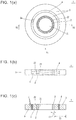
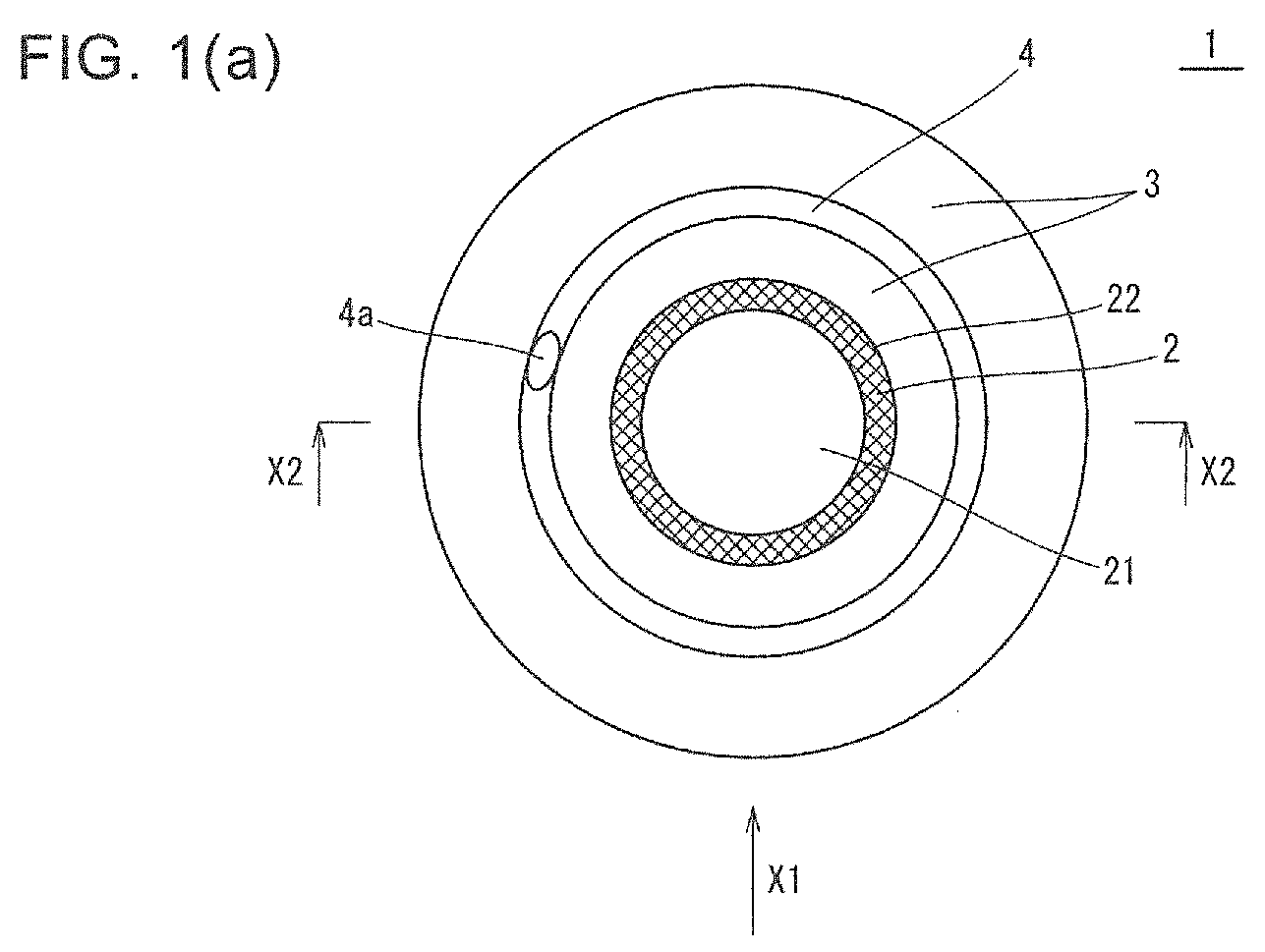
FIG. 1 is a diagram showing a sealing material in one embodiment of the present invention,FIG. 1(a) is a plan view of the sealing material,FIG. 1(b) is a side view taken in the direction of arrow X1 inFIG. 1(a), and FIG. 1(c) is a sectional view taken along line X2-X2 inFIG. 1(a) ; -
FIG. 2 is a schematic sectional view showing a sealing mechanism in an embodiment of the present invention; and -
FIG. 3 is a plan view showing a sealing material in another embodiment of the present invention. - A sealing material in one embodiment of the present invention is described in detail below with reference to
FIG. 1 . - As shown in
FIG. 1(a) , thesealing material 1 of the present embodiment has a cylindrical (ring-shaped) member and includes, as a constitutional member thereof, asliding layer 2, anelastic integument layer 3, and afastening fabric 4. The individual constitutional members of the sealingmaterial 1 of the present embodiment are described sequentially below. - The
sliding layer 2 is a cylindrical member, more specifically a circular cylindrical member. The slidinglayer 2 includes aninsertion hole 21. Theinsertion hole 21 is a portion designed to permit slidable insertion of a bar-shaped body. Specifically, the bar-shaped body of the present embodiment inserted into theinsertion hole 21 is acolumnar shaft 101 as shown inFIG. 2 described later. Theshaft 101 is a member subjected to relative movement, such as reciprocating motion or rotation, with respect to astructure 102. Theinsertion hole 21 of the present embodiment is configured so that theinsertion hole 21 and theshaft 101 slide upon each other when theshaft 101 in a state of being inserted into theinsertion hole 21 is moved relative to thestructure 102. - The sliding
layer 2 of the present embodiment which has the above configuration is composed of a material in which fiber and an elastic material are integrated with each other. With this configuration, sliding resistance to theshaft 101 is reducible, thus making it possible to produce excellent durability against sliding friction. - The fiber constituting the sliding
layer 2 is mainly intended to be brought into sliding contact with theshaft 101, and the fiber becomes a main factor reducing the sliding resistance to theshaft 101. Examples of the fibers include nylon fiber, polyester fiber, Teflon (registered trademark) fiber, liquid crystal polymer fiber, cotton thread, carbon fiber, glass fiber, and aramid fiber. These fibers exemplified above are usable by mixing one kind or two or more kinds thereof. - As a form of the fiber constituting the sliding
layer 2, there are, for example, fabric materials, such as woven fabrics, non-woven fabrics, and knitted fabrics. The woven fabrics includes canvases. Although a basis weight of the fabric material is usually 20-200 g/m2, no particular limitation is imposed thereon. - When the fiber is in the form of a fabric material, the fabric material and the elastic material are preferably integrated with each other so that the fabric material is brought into sliding contact with the
shaft 101. Specifically, the fabric material is preferably impregnated with the elastic material. Thereby, the elastic material enters between the fibers constituting the fabric material, thus making it possible to reinforce the fabric material. Furthermore, wear resistance is also improved because wear due to friction between the fabric materials is reducible. When impregnating the fabric material with the elastic material, the elastic material is preferably brought into a liquid state by being dissolved in a solvent or the like, in order to smoothly carry out an impregnation process. - The form of fibers may be, for example, short fibers besides the above-mentioned fabric material. When the form of the fibers is short fibers, the short fibers are preferably mixed into the elastic material, followed by integral formation.
- The elastic material constituting the sliding
layer 2 is mainly intended to improve durability of the above-mentioned fibers. Examples of the elastic material include rubbers and elastomers. Examples of the rubbers include natural rubber, nitrile rubber, chloroprene rubber, hypalon, polybutadiene rubber, ethylene-propylene rubber (EPM), ethylene-propylene-diene rubber terpolymer (EPDM), hydrogenated acrylonitrile butadiene rubber (H-NBR), silicone rubber, fluoro rubber, acryl rubber, styrene butadiene rubber, and chlorinated polyethylene rubber. Examples of the elastomers include millable urethane, thermoplastic polyurethane, thermoplastic polyurethane, and thermosetting polyester. These elastic materials exemplified above are usable by mixing one kind or two or more kinds thereof. - Additives may be added to the elastic material constituting the sliding
layer 2. Examples of the additives include vulcanizing agents, vulcanization accelerators, and reinforcing agents. Examples of the vulcanizing agents include organic peroxides, such as dicumyl peroxide, organic sulfur compounds, and metal oxides. Examples of the vulcanization accelerators include fatty acids, such as stearic acid, and metal oxide. Examples of the reinforcing agents include carbon black and white carbon. - As additives other than those described above, for example, an anti-aging agent, filler, plasticizer, adhesive, and solid lubricant may be added. Of these additives exemplified above, addition of the solid lubricant agent to the elastic material can contribute to reducing sliding resistance. Examples of the solid lubricants include graphite, silicone oil, fluorine powder, and molybdenum disulfide.
- The
elastic integument layer 3 is a member laminated on an outerperipheral surface 22 of the slidinglayer 2 described above as shown inFIG. 1(b) . Theelastic integument layer 3 is the member composed of an elastic material. During the relative movement of theshaft 101 with respect to thestructure 102, theelastic integument layer 3 follows up the relative movement so as to stabilize the shape of the slidinglayer 2, thereby functioning as a member that retains sealing property. - As an elastic material constituting the
elastic integument layer 3, the same elastic materials as exemplified above in the slidinglayer 2 can be illustrated. Additives may be added to the elastic material constituting the slidinglayer 2. Examples of the additives include vulcanizing agents, vulcanization accelerators, reinforcing agents, anti-aging agents, fillers, plasticizers, and adhesives. Of these additives exemplified above, examples of the vulcanizing agents, vulcanization accelerators, and reinforcing agents are the same as those exemplified above in the slidinglayer 2. - As shown in
FIG. 1(c) , a radial thickness T3 of theelastic integument layer 3 is larger than a radial thickness T2 of the slidinglayer 2 in the present embodiment. With this configuration, it is possible to improve the above-mentioned effect of retaining sealing property. - The
fastening fiber 4 is a member that enhances the compressive force of the sealingmaterial 1 onto theshaft 101, in other words, the fastening force onto theshaft 101. Thefastening fiber 4 is continuously wound from anend portion 4a thereof along a circumferential direction on the inside of theelastic integument layer 3 in the present embodiment. More specifically, thefastening fiber 4 is continuously wound in a state of being uncontacted with the outerperipheral surface 22 of the slidinglayer 2 over at least one convolution along the circumferential direction on the inside of theelastic integument layer 3. With this configuration, the fastening force of the sealingmaterial 1 can be enhanced. Consequently, excellent durability and sealing property are producible, thus leading to long-term use under high load. Furthermore, a high fastening force occurs due to the structure of the sealingmaterial 1 in the present embodiment. Hence, unlike conventional ones, there is no need for the strict tolerance setting with respect to the attachment member, such as the attachment hole for attaching the sealing material, thus permitting flexible designs. - Examples of the
fastening fiber 4 include the same fibers as exemplified above in the slidinglayer 2. Thefastening fiber 4 is particularly preferably at least one kind selected from among the carbon fibers, glass fibers, and aramid fibers. Because each of the carbon fibers, glass fibers, and aramid fibers has inflexibility, it is possible to enhance the fastening force of the sealingmaterial 1. - The
fastening fiber 4 of the present embodiment has the following configuration from the viewpoint of enhancing the fastening force of the sealingmaterial 1. Thefastening fiber 4 of the present embodiment has a filamentous shape. In the present embodiment, a plurality of thefastening fibers 4 are bundled into the filamentous shape. Thefastening fibers 4 are wound over a plurality of convolutions, and thefastening fibers 4 are wound helically in the present embodiment. Additionally, thefastening fibers fastening fibers 4 can be wound tightly on the inside of theelastic integument layer 3, thus enhancing the fastening force of the sealingmaterial 1. - The sealing
material 1 of the present embodiment having the above configurations is manufacturable, for example, in the following manner. Firstly, a fabric material being impregnated with an elastic material is wound over at least one layer around a bar-shaped object having the same shape as theshaft 101, thereby obtaining a first layer constituting the slidinglayer 2. Subsequently, an elastic material constituting theelastic integument layer 3 is wound over at least one layer around an outer peripheral surface of the first layer, thereby obtaining a second layer. Subsequently, thefastening fiber 4 is continuously wound over at least one convolution along the circumferential direction on the outer peripheral surface of the second layer so as to be uncontacted with the outer peripheral surface of the first layer. Thereafter, an elastic material constituting theelastic integument layer 3 is wound therearound over at least one layer, thereby obtaining a third layer. Finally, a laminated cylindrical body in which the first layer, the second layer, and the third layer are laminated in this order is accommodated between upper and lower metal molds capable of forming the laminated cylindrical body into the shape of the sealingmaterial 1. The individual layers are bonded to one another by heating under pressure, and are then taken out of the metal molds and cut in a necessary thickness, thereby obtaining the sealingmaterial 1. - A sealing mechanism in an embodiment of the present invention is described in detail below with reference to
FIG. 2 by taking, for example, the case of using the sealingmaterial 1 described above. - As shown in
FIG. 2 , thesealing mechanism 100 of the present embodiment has such a configuration that the space between ahole 103 of thestructure 102 and theshaft 101, which is the bar-shaped body being inserted into thehole 103, is sealed by the above-mentionedsealing material 1. With this configuration, the sealingmaterial 1 producing the excellent durability and sealing property seals the space between thehole 103 of thestructure 102 and theshaft 101 being inserted into thehole 103. It is therefore possible to preventforeign matter 110, such as powder attached to theshaft 101, from entering thehole 103 over a long period of time. The configuration of thesealing mechanism 100 of the present embodiment is specifically described below. - The
structure 102 in thesealing mechanism 100 includes a concave-shaped sealingmaterial accommodating part 104 located in the vicinity of an opening of thehole 103. The sealingmaterial accommodating part 104 has an inner diameter which is somewhat smaller than a diameter of the sealingmaterial 1, and which is larger than an inner diameter of thehole 103. Thehole 103 has a larger inner diameter than a diameter of theshaft 101. With these configurations, after theshaft 101 is inserted into thehole 103 of thestructure 102 by inserting theshaft 101 into theinsertion hole 21 of the sealingmaterial 1, the sealingmaterial 1 can be accommodated in a press-fitted state within the sealingmaterial accommodating part 104. Alternatively, after the sealingmaterial 1 is accommodated in the press-fitted state within the sealingmaterial accommodating part 104, theshaft 101 may be inserted into thehole 103 of thestructure 102 through theinsertion hole 21 of the sealingmaterial 1. - After the sealing
material 1 is accommodated within the sealingmaterial accommodating part 104, a retainingmember 105 is secured around an edge part of an opening of the sealingmaterial accommodating part 104. This makes it possible to prevent the sealingmaterial 1 from dropping out from the sealingmaterial accommodating part 104. - The
foreign matter 110, such as the powder being attached to theshaft 101, is removable by reciprocating motion of theshaft 101 with respect to thestructure 102. Specifically, the reciprocating motion of theshaft 101 with respect to thestructure 102 can cause theforeign matter 110 being attached to theshaft 101 to move toward theelastic integument layer 3 of the sealingmaterial 1, thus making it possible to remove theforeign matter 110 from theshaft 101. - A front surface of the sealing
material 1 located on a side, from which theforeign matter 110 may enter, is formed vertical to theshaft 101 in the present embodiment. Alternatively, the front surface of the sealingmaterial 1 may be inclined so as to be away from thehole 103 as going from an outer peripheral surface of the sealingmaterial 1 toward an inner peripheral surface side. With this configuration, theforeign matter 110 is highly efficiently removable from theshaft 101. - The sealing
material 1 and thesealing mechanism 100 in the foregoing embodiments are suitably usable for driving apparatuses handling powders or liquids. Examples of the driving apparatuses include vehicles, such as automobiles, motorbikes, motorcycles, amusement vehicles, motorboats, railway vehicles, ships, aircrafts, and spaceships, industrial machines, such as various machines, machine tools, robots, as well as industrial machines, such as production facilities, image processing apparatuses, semiconductor manufacturing apparatuses, chip mounters, and straight moving members, such as ball screws, each of which is easily affected by vibration, without being limited thereto. - Although the preferred embodiments of the present invention have been illustrated and described above, it is, of course, possible to make any arbitrary ones insofar as they do not depart from the gist of the present invention.
- For example, in the above embodiment, the
fastening fiber 4 is continuously wound in the state of being uncontacted with the outerperipheral surface 22 of the slidinglayer 2 over at least one convolution along the circumferential direction on the inside of theelastic integument layer 3. Alternatively, thefastening fiber 4 may be wound as shown inFIG. 3 . In a sealingmaterial 10 shown inFIG. 3 , thefastening fiber 4 is continuously wound over at least one convolution along the circumferential direction of an outerperipheral surface 31 of theelastic integument layer 3. This configuration is also capable of enhancing the fastening force of the sealingmaterial 10 as in the case of the sealingmaterial 1 of the foregoing embodiment. - Other configurations are similar to those in the sealing
material 1 of the foregoing embodiment, and their respective descriptions are therefore omitted here. - Although the
fastening fiber 4 has the filamentous shape in the foregoing embodiment, thefastening fiber 4 may have any shape other than the filamentous shape. Examples of other shapes include a shape obtainable by knitting thefastening fiber 4. - The
fastening fibers fastening fibers - Although the bar-shaped body is the
columnar shaft 101 in the foregoing embodiment, the bar-shaped body is not limited to thecolumnar shaft 101. The shape of theshaft 101 is not limited to the columnar shape, and other shapes may be employed. Examples of the other shapes include polygonal cylindrical shapes. -
- 1, 10
- sealing material
- 2
- sliding layer
- 21
- insertion hole
- 22
- outer peripheral surface
- 3
- elastic integument layer
- 31
- outer peripheral surface
- 4
- fastening fiber
- 4a
- end portion
- 100
- sealing mechanism
- 101
- shaft
- 102
- structure
- 103
- hole
- 104
- sealing material accommodating part
- 105
- retaining member
- 110
- foreign matter
Claims (8)
- A sealing material comprising:a cylindrical sliding layer comprising an insertion hole designed to permit slidable insertion of a bar-shaped body, the cylindrical sliding layer comprising a material in which a fiber and an elastic material are integrated with each other;an elastic integument layer laminated on an outer peripheral surface of the sliding layer; anda fastening fiber continuously wound in a state of being uncontacted with the outer peripheral surface of the sliding layer over at least one convolution along a circumferential direction on an inside of the elastic integument layer or an outer peripheral surface of the elastic integument layer.
- The sealing material according to claim 1, wherein the fastening fiber comprises at least one kind selected from among carbon fibers, glass fibers, and aramid fibers.
- The sealing material according to claim 1 or 2, wherein the fastening fiber has a filamentous shape.
- The sealing material according to any one of claims 1 to 3, wherein the fastening fiber is wound over a plurality of convolutions.
- The sealing material according to claim 4, wherein the fastening fiber is helically wound.
- The sealing material according to claim 4 or 5, wherein the fastening fibers adjacent to each other are contacted with each other.
- The sealing material according to any one of claims 1 to 6, wherein a radial thickness of the elastic integument layer is larger than a radial thickness of the sliding layer.
- A sealing mechanism in which a space between a hole of a structure and a bar-shaped body being inserted into the hole is sealed by a sealing material according to any one of claims 1 to 7.
Applications Claiming Priority (2)
| Application Number | Priority Date | Filing Date | Title |
|---|---|---|---|
| JP2015181608A JP2017057891A (en) | 2015-09-15 | 2015-09-15 | Seal material and seal mechanism |
| PCT/JP2016/075502 WO2017047386A1 (en) | 2015-09-15 | 2016-08-31 | Sealing material and sealing mechanism |
Publications (2)
| Publication Number | Publication Date |
|---|---|
| EP3351832A1 true EP3351832A1 (en) | 2018-07-25 |
| EP3351832A4 EP3351832A4 (en) | 2019-05-01 |
Family
ID=58288934
Family Applications (1)
| Application Number | Title | Priority Date | Filing Date |
|---|---|---|---|
| EP16846257.0A Withdrawn EP3351832A4 (en) | 2015-09-15 | 2016-08-31 | Sealing material and sealing mechanism |
Country Status (7)
| Country | Link |
|---|---|
| US (1) | US20180245694A1 (en) |
| EP (1) | EP3351832A4 (en) |
| JP (1) | JP2017057891A (en) |
| KR (1) | KR20180053275A (en) |
| CN (1) | CN107614946A (en) |
| TW (1) | TWI677637B (en) |
| WO (1) | WO2017047386A1 (en) |
Family Cites Families (17)
| Publication number | Priority date | Publication date | Assignee | Title |
|---|---|---|---|---|
| US1676432A (en) * | 1925-04-10 | 1928-07-10 | Francis L Dieterich | Acking material and gasket made therefrom |
| JPS58109660U (en) * | 1982-01-22 | 1983-07-26 | 日本ピラ−工業株式会社 | Grand Patsukin |
| US5217797A (en) * | 1992-02-19 | 1993-06-08 | W. L. Gore & Associates, Inc. | Chemically resistant diaphragm |
| AUPO076596A0 (en) * | 1996-07-02 | 1996-07-25 | Bucknell, John Wentworth | Seals for hydraulic assemblies |
| JP2952764B2 (en) * | 1997-05-07 | 1999-09-27 | 日本ピラー工業株式会社 | Filler material for spiral wound gasket and spiral wound gasket using the filler material |
| CN1230636C (en) * | 1999-11-12 | 2005-12-07 | 盖茨公司 | Power transmission belts using open mesh textile materials |
| JP2002201461A (en) * | 2001-11-12 | 2002-07-19 | Tsuchiya Tsco Co Ltd | Sealing material |
| JP4125905B2 (en) * | 2002-03-14 | 2008-07-30 | 日本ピラー工業株式会社 | Sealing structure |
| EP1496293A4 (en) * | 2002-03-25 | 2007-12-12 | Nsk Ltd | Seal ring, and roller bearing unit with seal ring |
| JP4249041B2 (en) * | 2004-01-19 | 2009-04-02 | 三和テクノ株式会社 | Rotating body sealing material and method of using the same, rotating body device, developing device, and image forming apparatus |
| JP2007256691A (en) * | 2006-03-24 | 2007-10-04 | Nichiyo Keori Kk | Leak prevention material for fine particle |
| CN104040230B (en) * | 2012-03-30 | 2016-03-02 | Kyb株式会社 | The seal construction of caterpillar drive |
| KR102058637B1 (en) * | 2012-06-22 | 2019-12-23 | 니타 가부시키가이샤 | Ball screw, seal material, and seal structure |
| WO2014102897A1 (en) * | 2012-12-25 | 2014-07-03 | 三和テクノ株式会社 | Cylindrical shaft-sealing material obtained from pile weave or knit |
| JP6313982B2 (en) * | 2014-01-29 | 2018-04-18 | ニッタ株式会社 | Seal material and seal mechanism |
| CN204253858U (en) * | 2014-11-19 | 2015-04-08 | 张家港市三利密封合金材料有限公司 | A kind of high-elastic locking washer |
| CN104455420B (en) * | 2014-11-19 | 2016-10-05 | 张家港市三利密封合金材料有限公司 | A kind of sealing strip of composite construction |
-
2015
- 2015-09-15 JP JP2015181608A patent/JP2017057891A/en active Pending
-
2016
- 2016-08-31 EP EP16846257.0A patent/EP3351832A4/en not_active Withdrawn
- 2016-08-31 US US15/760,318 patent/US20180245694A1/en not_active Abandoned
- 2016-08-31 KR KR1020177034199A patent/KR20180053275A/en not_active Abandoned
- 2016-08-31 CN CN201680031093.1A patent/CN107614946A/en active Pending
- 2016-08-31 WO PCT/JP2016/075502 patent/WO2017047386A1/en not_active Ceased
- 2016-09-13 TW TW105129757A patent/TWI677637B/en not_active IP Right Cessation
Also Published As
| Publication number | Publication date |
|---|---|
| JP2017057891A (en) | 2017-03-23 |
| US20180245694A1 (en) | 2018-08-30 |
| WO2017047386A1 (en) | 2017-03-23 |
| TWI677637B (en) | 2019-11-21 |
| EP3351832A4 (en) | 2019-05-01 |
| KR20180053275A (en) | 2018-05-21 |
| TW201716708A (en) | 2017-05-16 |
| CN107614946A (en) | 2018-01-19 |
Similar Documents
| Publication | Publication Date | Title |
|---|---|---|
| US9488255B2 (en) | Ball screw, seal material, and seal structure | |
| CN106795915B (en) | Synthetic resin retainer and ball bearing | |
| JP6313982B2 (en) | Seal material and seal mechanism | |
| US20180245694A1 (en) | Sealing material and sealing mechanism | |
| EP2778446A1 (en) | Dust cover for ball joint | |
| JP2008286387A (en) | Bearing for automobile auxiliary machine | |
| JP6602645B2 (en) | Sealing material fixing structure | |
| JP6470050B2 (en) | Seal material and seal mechanism | |
| KR20180051391A (en) | Sealing structure | |
| JP5424573B2 (en) | Tenter Clip Guide Bearing | |
| TWI630335B (en) | Sealing material and sealing mechanism | |
| JP2015197179A (en) | Seal material and seal mechanism | |
| JP2023084864A (en) | Fluid pressure actuator | |
| CN106917817B (en) | Tapered roller bearing | |
| JP6174476B2 (en) | Friction damper | |
| JP2015232371A (en) | Seal material and seal mechanism | |
| JP2017078438A (en) | Foreign matter invasion preventing wall | |
| JP2023151690A (en) | Sealing material using cylindrical fabric | |
| JP2016109174A (en) | Dust cover | |
| JP2015055255A (en) | Rolling guide device | |
| JP2005155852A (en) | High load transmission belt |
Legal Events
| Date | Code | Title | Description |
|---|---|---|---|
| PUAI | Public reference made under article 153(3) epc to a published international application that has entered the european phase |
Free format text: ORIGINAL CODE: 0009012 |
|
| 17P | Request for examination filed |
Effective date: 20180201 |
|
| AK | Designated contracting states |
Kind code of ref document: A1 Designated state(s): AL AT BE BG CH CY CZ DE DK EE ES FI FR GB GR HR HU IE IS IT LI LT LU LV MC MK MT NL NO PL PT RO RS SE SI SK SM TR |
|
| AX | Request for extension of the european patent |
Extension state: BA ME |
|
| DAV | Request for validation of the european patent (deleted) | ||
| DAX | Request for extension of the european patent (deleted) | ||
| A4 | Supplementary search report drawn up and despatched |
Effective date: 20190403 |
|
| RIC1 | Information provided on ipc code assigned before grant |
Ipc: G03G 15/00 20060101ALI20190328BHEP Ipc: F16J 15/24 20060101AFI20190328BHEP Ipc: G03G 15/08 20060101ALI20190328BHEP Ipc: F16J 15/20 20060101ALI20190328BHEP Ipc: F16J 15/3204 20160101ALI20190328BHEP Ipc: F16H 25/24 20060101ALI20190328BHEP |
|
| GRAP | Despatch of communication of intention to grant a patent |
Free format text: ORIGINAL CODE: EPIDOSNIGR1 |
|
| INTG | Intention to grant announced |
Effective date: 20191212 |
|
| STAA | Information on the status of an ep patent application or granted ep patent |
Free format text: STATUS: THE APPLICATION IS DEEMED TO BE WITHDRAWN |
|
| 18D | Application deemed to be withdrawn |
Effective date: 20200603 |