EP3351426A1 - Tray table trays - Google Patents
Tray table trays Download PDFInfo
- Publication number
- EP3351426A1 EP3351426A1 EP17194836.7A EP17194836A EP3351426A1 EP 3351426 A1 EP3351426 A1 EP 3351426A1 EP 17194836 A EP17194836 A EP 17194836A EP 3351426 A1 EP3351426 A1 EP 3351426A1
- Authority
- EP
- European Patent Office
- Prior art keywords
- top surface
- casing
- tray
- aperture
- receptacle
- Prior art date
- Legal status (The legal status is an assumption and is not a legal conclusion. Google has not performed a legal analysis and makes no representation as to the accuracy of the status listed.)
- Granted
Links
Images



Classifications
-
- B—PERFORMING OPERATIONS; TRANSPORTING
- B60—VEHICLES IN GENERAL
- B60N—SEATS SPECIALLY ADAPTED FOR VEHICLES; VEHICLE PASSENGER ACCOMMODATION NOT OTHERWISE PROVIDED FOR
- B60N3/00—Arrangements or adaptations of other passenger fittings, not otherwise provided for
- B60N3/001—Arrangements or adaptations of other passenger fittings, not otherwise provided for of tables or trays
- B60N3/002—Arrangements or adaptations of other passenger fittings, not otherwise provided for of tables or trays of trays
-
- A—HUMAN NECESSITIES
- A47—FURNITURE; DOMESTIC ARTICLES OR APPLIANCES; COFFEE MILLS; SPICE MILLS; SUCTION CLEANERS IN GENERAL
- A47G—HOUSEHOLD OR TABLE EQUIPMENT
- A47G23/00—Other table equipment
- A47G23/06—Serving trays
-
- B—PERFORMING OPERATIONS; TRANSPORTING
- B61—RAILWAYS
- B61D—BODY DETAILS OR KINDS OF RAILWAY VEHICLES
- B61D37/00—Other furniture or furnishings
-
- A—HUMAN NECESSITIES
- A47—FURNITURE; DOMESTIC ARTICLES OR APPLIANCES; COFFEE MILLS; SPICE MILLS; SUCTION CLEANERS IN GENERAL
- A47G—HOUSEHOLD OR TABLE EQUIPMENT
- A47G23/00—Other table equipment
- A47G23/03—Underlays for glasses or drinking-vessels
-
- B—PERFORMING OPERATIONS; TRANSPORTING
- B60—VEHICLES IN GENERAL
- B60N—SEATS SPECIALLY ADAPTED FOR VEHICLES; VEHICLE PASSENGER ACCOMMODATION NOT OTHERWISE PROVIDED FOR
- B60N3/00—Arrangements or adaptations of other passenger fittings, not otherwise provided for
- B60N3/001—Arrangements or adaptations of other passenger fittings, not otherwise provided for of tables or trays
-
- B—PERFORMING OPERATIONS; TRANSPORTING
- B60—VEHICLES IN GENERAL
- B60N—SEATS SPECIALLY ADAPTED FOR VEHICLES; VEHICLE PASSENGER ACCOMMODATION NOT OTHERWISE PROVIDED FOR
- B60N3/00—Arrangements or adaptations of other passenger fittings, not otherwise provided for
- B60N3/001—Arrangements or adaptations of other passenger fittings, not otherwise provided for of tables or trays
- B60N3/002—Arrangements or adaptations of other passenger fittings, not otherwise provided for of tables or trays of trays
- B60N3/004—Arrangements or adaptations of other passenger fittings, not otherwise provided for of tables or trays of trays of foldable trays mounted on the back-rest
-
- B—PERFORMING OPERATIONS; TRANSPORTING
- B61—RAILWAYS
- B61D—BODY DETAILS OR KINDS OF RAILWAY VEHICLES
- B61D33/00—Seats
- B61D33/0007—Details; Accessories
-
- B—PERFORMING OPERATIONS; TRANSPORTING
- B64—AIRCRAFT; AVIATION; COSMONAUTICS
- B64D—EQUIPMENT FOR FITTING IN OR TO AIRCRAFT; FLIGHT SUITS; PARACHUTES; ARRANGEMENT OR MOUNTING OF POWER PLANTS OR PROPULSION TRANSMISSIONS IN AIRCRAFT
- B64D11/00—Passenger or crew accommodation; Flight-deck installations not otherwise provided for
- B64D11/0007—Devices specially adapted for food or beverage distribution services
-
- B—PERFORMING OPERATIONS; TRANSPORTING
- B64—AIRCRAFT; AVIATION; COSMONAUTICS
- B64D—EQUIPMENT FOR FITTING IN OR TO AIRCRAFT; FLIGHT SUITS; PARACHUTES; ARRANGEMENT OR MOUNTING OF POWER PLANTS OR PROPULSION TRANSMISSIONS IN AIRCRAFT
- B64D11/00—Passenger or crew accommodation; Flight-deck installations not otherwise provided for
- B64D11/06—Arrangements of seats, or adaptations or details specially adapted for aircraft seats
-
- B—PERFORMING OPERATIONS; TRANSPORTING
- B64—AIRCRAFT; AVIATION; COSMONAUTICS
- B64D—EQUIPMENT FOR FITTING IN OR TO AIRCRAFT; FLIGHT SUITS; PARACHUTES; ARRANGEMENT OR MOUNTING OF POWER PLANTS OR PROPULSION TRANSMISSIONS IN AIRCRAFT
- B64D11/00—Passenger or crew accommodation; Flight-deck installations not otherwise provided for
- B64D11/06—Arrangements of seats, or adaptations or details specially adapted for aircraft seats
- B64D11/0602—Seat modules, i.e. seat systems including furniture separate from the seat itself
- B64D11/0605—Seat modules, i.e. seat systems including furniture separate from the seat itself including tables or desks
-
- B—PERFORMING OPERATIONS; TRANSPORTING
- B64—AIRCRAFT; AVIATION; COSMONAUTICS
- B64D—EQUIPMENT FOR FITTING IN OR TO AIRCRAFT; FLIGHT SUITS; PARACHUTES; ARRANGEMENT OR MOUNTING OF POWER PLANTS OR PROPULSION TRANSMISSIONS IN AIRCRAFT
- B64D11/00—Passenger or crew accommodation; Flight-deck installations not otherwise provided for
- B64D11/06—Arrangements of seats, or adaptations or details specially adapted for aircraft seats
- B64D11/0638—Arrangements of seats, or adaptations or details specially adapted for aircraft seats with foldable tables, trays or cup holders
-
- B—PERFORMING OPERATIONS; TRANSPORTING
- B65—CONVEYING; PACKING; STORING; HANDLING THIN OR FILAMENTARY MATERIAL
- B65D—CONTAINERS FOR STORAGE OR TRANSPORT OF ARTICLES OR MATERIALS, e.g. BAGS, BARRELS, BOTTLES, BOXES, CANS, CARTONS, CRATES, DRUMS, JARS, TANKS, HOPPERS, FORWARDING CONTAINERS; ACCESSORIES, CLOSURES, OR FITTINGS THEREFOR; PACKAGING ELEMENTS; PACKAGES
- B65D81/00—Containers, packaging elements, or packages, for contents presenting particular transport or storage problems, or adapted to be used for non-packaging purposes after removal of contents
- B65D81/24—Adaptations for preventing deterioration or decay of contents; Applications to the container or packaging material of food preservatives, fungicides, pesticides or animal repellants
- B65D81/26—Adaptations for preventing deterioration or decay of contents; Applications to the container or packaging material of food preservatives, fungicides, pesticides or animal repellants with provision for draining away, or absorbing, or removing by ventilation, fluids, e.g. exuded by contents; Applications of corrosion inhibitors or desiccators
- B65D81/261—Adaptations for preventing deterioration or decay of contents; Applications to the container or packaging material of food preservatives, fungicides, pesticides or animal repellants with provision for draining away, or absorbing, or removing by ventilation, fluids, e.g. exuded by contents; Applications of corrosion inhibitors or desiccators for draining or collecting liquids without absorbing them
-
- B—PERFORMING OPERATIONS; TRANSPORTING
- B65—CONVEYING; PACKING; STORING; HANDLING THIN OR FILAMENTARY MATERIAL
- B65D—CONTAINERS FOR STORAGE OR TRANSPORT OF ARTICLES OR MATERIALS, e.g. BAGS, BARRELS, BOTTLES, BOXES, CANS, CARTONS, CRATES, DRUMS, JARS, TANKS, HOPPERS, FORWARDING CONTAINERS; ACCESSORIES, CLOSURES, OR FITTINGS THEREFOR; PACKAGING ELEMENTS; PACKAGES
- B65D81/00—Containers, packaging elements, or packages, for contents presenting particular transport or storage problems, or adapted to be used for non-packaging purposes after removal of contents
- B65D81/24—Adaptations for preventing deterioration or decay of contents; Applications to the container or packaging material of food preservatives, fungicides, pesticides or animal repellants
- B65D81/26—Adaptations for preventing deterioration or decay of contents; Applications to the container or packaging material of food preservatives, fungicides, pesticides or animal repellants with provision for draining away, or absorbing, or removing by ventilation, fluids, e.g. exuded by contents; Applications of corrosion inhibitors or desiccators
- B65D81/264—Adaptations for preventing deterioration or decay of contents; Applications to the container or packaging material of food preservatives, fungicides, pesticides or animal repellants with provision for draining away, or absorbing, or removing by ventilation, fluids, e.g. exuded by contents; Applications of corrosion inhibitors or desiccators for absorbing liquids
Definitions
- This disclosure relates generally to portable tables and, more particularly, to trays for use in tray tables that prevent liquids spilled on a top surface of the tray from spreading over the edges of the top surface and provide for easy cleanup.
- Tray tables generally consist of a tray mounted on folding legs or a tray mounted on or in a piece of furniture, such as an airplane or train seatback, and designed to fold or swing out of the way for storage.
- a tray table may be stowed flat against an airplane seatback and readily folded down to a generally horizontal usable position to provide a surface upon which a passenger can place a drink and/or eat a meal.
- Such trays are typically affixed to the seatback by a pair of arms that are pivotally attached to the seatback and to the tray, and often have a top surface with recessed areas therein where glasses, bottles, cups or cans can be placed.
- the recessed areas reduce the risk of knocking over the glasses, bottles, cups or cans, but they do not prevent liquid from spreading over the tray's top surface or over the edges of the tray once a liquid has been spilled.
- Tray table trays are typically made from a lightweight plastic-type material or other materials that are hydrophobic. Spilled liquids can freely spread over the tray surface and drip over the edges of the tray, dirtying the vehicle interior and the passenger's clothing. This can influence passenger satisfaction, and requires that the spill be cleaned up prior to the next departure for the vehicle. For liquids that are difficult remove, such as red wine, additional time and cleaning supplies may be necessary.
- the tray comprises a casing having a top surface with at least one aperture through the top surface and a receptacle within the casing positioned below the aperture in the top surface.
- the receptacle is configured to receive an absorbent pad, which can be removably positioned in the receptacle below the aperture to be in communication with the top surface, such that liquid spilled on the top surface can flow through the aperture and into the absorbent pad.
- the absorbent pad can be a superabsorbent material that can absorb and retain large amounts of a liquid relative to its own mass so that it quickly absorbs any spilled liquid on the top surface of the tray and reduces the frequency of having to replace the absorbent material.
- a superhydrophobic coating can be applied on the top surface of the casing to provide a high degree of liquid repellency.
- the geometry of the top surface can be configured to guide any liquid spilled on the tray toward the aperture through the top surface and into the absorbent pad.
- the top surface comprises three elongated apertures positioned proximate three sides (a rear side, a left side and a right side) of the casing.
- the top surface of the casing can be generally flat and may have a raised edge at a front side of the casing that forms a barrier to prevent a liquid spilled on the top surface from dripping over the raised edge and to guide the liquid toward the elongated apertures in the rear side, the left side and the right side of the casing.
- the top surface comprises at least one sloped portion that is sloped down toward and terminates at the aperture through the top surface.
- the sloped portion can guide a liquid spilled on the top surface toward the aperture and into the absorbent pad.
- the slope of the sloped portion can be slight, just enough to provide the guiding function without causing objects placed on the sloped portion to fall over.
- the top surface may have a single elongated aperture extending generally parallel to, and positioned proximate, a rear side of the casing, such that the elongated aperture extends a substantial part of the width of the rear side.
- the sloped portion of the top surface may have a width at least as wide as the width of the elongated aperture and the slope of the sloped portion may cause the front side of the top surface to be at a higher level than the rear side of the top surface.
- the top surface can include a first raised edge at a left side of the casing and a second raised edge at right side of the casing to form a barrier to prevent a liquid spilled on the top surface from dripping over the left side and the right side of the casing and to further guide the liquid toward the elongated aperture.
- the aperture is positioned proximate a center of the top surface and the top surface comprising four slopes extending from the right side, left side, rear side and front side of the casing down toward the aperture in the center of the top surface.
- the slope of the sloped portions can cause the center of the top surface to be at a lower level than all of the sides of the top surface, and permit the aperture to act as a central drain.
- a method for manufacturing a tray for tray table that can prevent a liquid spilled on a top surface of the tray from spreading over an edge of the tray.
- the method includes the steps of forming a casing having a receptacle within the casing and a top surface with at least one aperture through the top surface in communication with the receptacle, such that during use a removable absorbent pad can be inserted in the receptacle below the aperture and in communication with the top surface.
- the absorbent pad can be a superabsorbent material that can absorb and retain large amounts of a liquid relative to its own mass so that it quickly absorbs any spilled liquid on the top surface of the tray and reduces the frequency of having to replace the absorbent material.
- the step of forming the casing can include forming an opening through a side of the casing in communication with the receptacle, such that the removable absorbent pad may be inserted and removed from the receptacle through the opening, applying a superhydrophobic coating on the top surface of the casing to provide a high degree of liquid repellency, and configuring the top surface to guide any liquid spilled on the tray toward the aperture through the top surface and into the absorbent pad.
- the trays described herein can prevent spilled liquids from spreading outside the tray surface and provide for quick and easy clean-up.
- the foregoing benefit as well as others, are achieved by a tray for a tray table that collects liquid spilled on a top surface of the tray in a replaceable absorbent pad positioned in a receptacle within the tray, and therefore reduces the risk of spilled liquid spreading over edges of the tray and dirtying the surrounding area and user of the tray table.
- the replaceable pad is easily inserted into and removed from the receptacle in the tray, and can include an indicator for indicating when the absorbent pad has reached maximum capacity and requires replacement.
- a tray 10 for a tray table and methods for preventing a liquid spilled on a top surface 12 of a tray 10 from spreading over an edge 14 of the tray 10 are described.
- the description is merely exemplary in nature and is not intended to limit the disclosed tray or the application and uses of the disclosed tray. It will be recognized by one skilled in the art that the present disclosure may be practiced in a variety of applications or environments and/or with other analogous or equivalent variations of the illustrative examples.
- the concepts and teachings disclosed herein may be applied to a tray of the type used with tray tables on seatbacks in aircraft, trains and other vehicles, or any other type of portable table or surface upon which a liquid could spill.
- the tray 10 comprises a casing 16 having a top surface 12 with at least one aperture 18 through the top surface 12.
- the aperture 18 acts as a drain for liquid that is spilled on the top surface 12.
- the aperture 18 may take any form including, without limitation, a round, square or rectangular shaped hole or slot.
- the aperture 18 need not be covered, but may have a pervious or mesh cover placed over the aperture 18.
- the casing 16 may be made from any type of lightweight, moldable and sturdy material, such as aluminum, metal or plastic, and formed into a shape suitable for a particular use.
- the tray 10 may have a generally rectangular shape and be used in a tray table that is pivotably and foldably attached to a seatback in an airplane or train, such that the tray table can be selectively folded down by a passenger seated in the immediately rearward seat.
- a receptacle 20 is positioned within the casing 16 and below the aperture 18 in the top surface 12, and configured to receive an absorbent pad 22 that can be removably positioned in the receptacle 20 below the aperture 18 to be in communication with the top surface 12.
- the absorbent pad 22 is configured to absorb liquid that spills on the top surface 12 and enters the aperture 18.
- the receptacle 20 extends under substantially an entire area 13 of the top surface 12, and the absorbent pad 22 substantially fills the receptacle 20 such that the absorbent pad 22 fills between about 25% to 80% of the volume of the receptacle 20.
- the casing 16 has an opening 24 in a side 26 of the casing 16 in communication with the receptacle 20 that permits insertion and removal of the absorbent pad 22 into and out of the receptacle 20.
- a locking device 28 may optionally be included for maintaining the absorbent pad 22 in the receptacle 20.
- a pivotable bar 30 may be positioned on the side 26 of the casing 16 to rotate about a pivot point 32 positioned above or below the opening 24, such that the pivotable bar 30 is moveable between a horizontal position that permits entry of the absorbent pad 22 and a vertical position that blocks the opening 24 and prevents the absorbent pad 22 from being removed.
- An absorbent pad 22 that does not require frequent replacement, and can be used until the absorbent pad 22 reaches its maximum capacity without leaking.
- An absorbent pad 22 comprising a superabsorbent material, such as a superabsorbent polymer (SAP) that can absorb and retain extremely large amounts of a liquid relative to its own mass, meets those goals.
- a SAP may absorb about 50 times its weight
- a SAP may absorb about 300 times its weight.
- Superabsorbent polymer is made from the polymerization of acrylic acid blended with sodium hydroxide in the presence of an initiator to form a poly-acrylic acid sodium salt (sometimes referred to as sodium polyacrylate).
- a poly-acrylic acid sodium salt sometimes referred to as sodium polyacrylate.
- Commercial products based on SAP materials are often referred to as slush powder.
- Superabsorbent polymers also act as smell absorbers, which will prevent odors from the liquid absorbed therein from permeating from the SAP, and therefore extend the life of the SAP before replacement.
- an absorbent, but not superabsorbent, silica gel - a SiO 2 based polymer - may be used instead of the SAP.
- the state of the absorbent pad 22 may be checked visually or by touch by sliding the absorbent pad 22 out of the receptacle 20.
- a visual indicator may be provided to assess the amount of liquid absorbed in the absorbent pad 22 and indicate when the absorbent pad 22 has reached its maximum capacity and should be replaced.
- a piece of material that dissolves in water-based liquids may be positioned at a point that is located in the furthermost spot from the aperture 18.
- SAP material or Silica gel may be doped with a moisture indicator that gradually changes its color when it transitions from the anhydrous (dry) state to the hydrated (wet) state.
- Common indicators are cobalt chloride and methyl violet.
- Digital humidity meters may also be located in at least three different locations inside the absorber, and the measurements can be combined and presented on the visible side of absorber, for example with LEDs or a simple LCD display. All such indicators may be checked either by sliding the absorbent pad 22 out of the receptacle 20 or through an optional window 34 through a bottom 36 of the casing 16, as shown in FIG. 13 , positioned below the absorbent pad 22.
- the window 34 is covered with a clear plastic or glass covering 38 that permits visual inspection of the absorbent pad 22.
- top surface 12 of the casing 16 that repels a liquid spilled on the top surface 12 (and prevents the liquid from permeating into the top surface 12) to assist the liquid's movement toward the aperture 18 and into the absorbent pad 22.
- One way to provide such a surface is to coat a superhydrophobic coating 40 on the top surface 12 of the casing 16 such that the superhydrophobic coating 40 becomes a part of the top surface 12.
- a superhydrophobic coating 40 is a nanoscopic surface layer that repels liquids. Droplets hitting the superhydrophobic coating 40 can fully rebound in the shape of a column or pancake and glide across the superhydrophobic coating 40.
- the property that is used for characterizing hydrophobicity of a material is the contact angle between a liquid droplet and the surface of material.
- Superhydrophobicity is achieved when the contact angle is above 150 degrees.
- the top surface 12 of the casing 16 should therefore have a contact angle between a liquid droplet and the top surface 12 greater than 150 degrees.
- Materials suitable for providing the superhydrophobic coating 40 are based on nano-composites like manganese oxide polystyrene, zinc oxide polystyrene, or silica nanoparticles. Examples of commercially-available materials suitable for the superhydrophobic coating 40 include, but are not limited to, NEVERWET® coatings available from NeverWet, LLC of Lancaster, Pennsylvania, superhydrophobic materials available from Aculon, Inc. of San Diego, California, and ULTRA EVER DRY® available from UltraTech International, Inc. of Jacksonville, Florida.
- top surface 12 of the casing 16 can be arranged in many different configurations to achieve the desired result of guiding a spilled liquid toward the at least one aperture 18 in the top surface such that the liquid is absorbed into the absorbent pad 22 positioned in the receptacle 20.
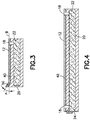
- Figures 1-4 show a first example of a surface geometry, wherein the top surface 12 comprises three elongated apertures 42.
- the elongated apertures 42 extend linearly generally parallel to, and are positioned proximate to, a rear side 44, a left side 46, and a right side 48 of the casing 16.
- the elongated apertures 42 have a width of about 3-6 mm to limit the capillary effect that could block liquid from efficiently moving through the aperture 18 to the absorbent pad 22, but other widths may be employed for different tray 10 designs.
- the top surface 12 of the casing 16 is generally flat and has a raised edge 50 at a front side 52 of the casing 16 that forms a barrier to prevent a liquid spilled on the top surface 12 from dripping over the raised edge 50.
- the raised edge 50 also serves to guide the liquid toward the elongated apertures 42 in the rear side 44, the left side 46, and the right side 48 of the casing 16.
- the raised edge 50 has an angle A relative to the plane B of the top surface 12 up to 90 degrees, and preferably greater than 30 degrees.
- the top surface 12 may also include one or more sloped portions having a slope of about 0.5 to 1.0 degree that are sloped down toward the elongated apertures 42.
- the sloped portions provide a direction for a liquid to move along the top surface 12, and may be used to reduce the number of apertures 18 or the size of the apertures 18.
- the top surface 12 of the casing 16 has at least one sloped portion 54 sloped down toward and terminating at the aperture 18 through the top surface 12.
- the slope S of the sloped portion 54 is slight, just enough to provide the guiding function without causing objects placed on the sloped portion to fall over, for example, the sloped portion 54 has a slope S of about 0.5 to 1.0 degree relative to a horizontal plane 56 of the casing 16.
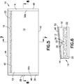
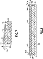
- FIGS. 5-8 show a tray 10 having a top surface 12 with a sloped portion 54 that is sloped from the front side 52 of the casing 16 down toward the rear side 44 of the casing; that is the slope S of the sloped portion 54 causes the front side 52 of the top surface 12 to be at a higher level than the rear side 44 of the top surface 12.
- the sloped portion 54 terminates at the aperture 18 through the top surface 12, which is configured in this example as a single elongated aperture 42 extending linearly generally parallel to, and positioned proximate to, the rear side 44 of the casing 16, such that the elongated aperture 42 extends a substantial part of the width of the rear side 44.
- the slope S of the sloped portion 54 guides a liquid spilled on the top surface 12 toward the aperture 18 and into the absorbent pad 22.
- the sloped portion 54 has a width at least as wide as the width of the elongated aperture 42.
- the top surface 12 of the casing 16 includes a first raised edge 50a at a left side 46 of the casing 16 and a second raised edge 50b at a right side 48 of the casing 16 to form a barrier to prevent a liquid spilled on the top surface 12 from dripping over the left side 46 and the right side 48 of the casing 16 and to further guide the liquid toward the elongated aperture 42.
- FIGS. 9-12 show another example of a tray 10 having sloped portions 54 in the top surface 12 of the casing 16.
- the aperture 18 is configured as a round hole that is positioned proximate a center 58 of the top surface 12.
- the hole in the center 58 need not be round; it could be square, rectangular or any other shape.
- the top surface 12 has four sloped portions 54 extending from a right side 48, a left side 46, a rear side 44, and a front side 52 of the casing 16 that all slope downward toward the aperture 18 in the center 58 of the top surface 12.
- the sloped portions 54 have a slope of about 0.5 to 1.0 degrees that causes the center 58 of the top surface 12 to be at a lower level than all of the sides of the top surface 12, and permits the aperture 18 to act as a central drain.
- the features described with respect to FIGS. 1-4 , FIGS. 5-8 , FIGS. 9-12 , and FIG. 13 can be combined in any number of ways that prevent a liquid from flowing over an edge of the tray 10 and/or to channel the liquid to the absorbent pad 22 within the casing 16.
- a method 100 for making a tray 10 for a tray table as shown in Figs. 1-13 that can prevent a liquid spilled on a top surface 12 of the tray 10 from spreading over an edge 14 of the tray 10 is provided.
- a casing 16 is formed having a receptacle 20 within the casing 16 and a top surface 12 with at least one aperture 18 through the top surface 12 in communication with the receptacle 20.
- a removable absorbent pad 22 is inserted into the receptacle 20 below the aperture 18 to be in communication with the top surface 12.
- the absorbent pad 22 can be a superabsorbent material that can absorb and retain large amounts of a liquid relative to its own mass so that it quickly absorbs any spilled liquid on the top surface 12 of the tray 10 and reduces the frequency of having to replace the absorbent pad 22.
- a superhydrophobic coating 40 can be coated on the top surface 12 of the casing 16 to provide a high degree of liquid repellency.
- the top surface 12 can be configured to guide any liquid spilled on the tray 10 toward the aperture 18 through the top surface 12 and into the absorbent pad 22.
- tray 10 has been described with reference to various embodiments, it will be understood by those skilled in the art that various changes may be made and equivalents may be substituted for elements thereof without departing from the teachings herein.
- shape of the tray 10 the area of the top surface 13, the angle A of the raised edge 50, and other elements may be adjusted to accommodate other design considerations.
- the tray 10 may be manufactured and sold with or without the absorbent pad.
Landscapes
- Engineering & Computer Science (AREA)
- Mechanical Engineering (AREA)
- Aviation & Aerospace Engineering (AREA)
- Transportation (AREA)
- Food Science & Technology (AREA)
- Sampling And Sample Adjustment (AREA)
- Passenger Equipment (AREA)
- Table Equipment (AREA)
- Details Of Rigid Or Semi-Rigid Containers (AREA)
- Packages (AREA)
- Vehicle Step Arrangements And Article Storage (AREA)
Abstract
Description
- This disclosure relates generally to portable tables and, more particularly, to trays for use in tray tables that prevent liquids spilled on a top surface of the tray from spreading over the edges of the top surface and provide for easy cleanup.
- Tray tables generally consist of a tray mounted on folding legs or a tray mounted on or in a piece of furniture, such as an airplane or train seatback, and designed to fold or swing out of the way for storage. For example, a tray table may be stowed flat against an airplane seatback and readily folded down to a generally horizontal usable position to provide a surface upon which a passenger can place a drink and/or eat a meal. Such trays are typically affixed to the seatback by a pair of arms that are pivotally attached to the seatback and to the tray, and often have a top surface with recessed areas therein where glasses, bottles, cups or cans can be placed. The recessed areas reduce the risk of knocking over the glasses, bottles, cups or cans, but they do not prevent liquid from spreading over the tray's top surface or over the edges of the tray once a liquid has been spilled.
- It is common, particularly in airplanes, trains and other vehicles, for drinks resting on a tray table surface to be spilled for various reasons such as vibration resulting from vehicle movement, severe turbulences and passenger inadvertence. Tray table trays are typically made from a lightweight plastic-type material or other materials that are hydrophobic. Spilled liquids can freely spread over the tray surface and drip over the edges of the tray, dirtying the vehicle interior and the passenger's clothing. This can influence passenger satisfaction, and requires that the spill be cleaned up prior to the next departure for the vehicle. For liquids that are difficult remove, such as red wine, additional time and cleaning supplies may be necessary.
- In accordance with some aspects of this disclosure, the tray comprises a casing having a top surface with at least one aperture through the top surface and a receptacle within the casing positioned below the aperture in the top surface. The receptacle is configured to receive an absorbent pad, which can be removably positioned in the receptacle below the aperture to be in communication with the top surface, such that liquid spilled on the top surface can flow through the aperture and into the absorbent pad. The absorbent pad can be a superabsorbent material that can absorb and retain large amounts of a liquid relative to its own mass so that it quickly absorbs any spilled liquid on the top surface of the tray and reduces the frequency of having to replace the absorbent material. A superhydrophobic coating can be applied on the top surface of the casing to provide a high degree of liquid repellency. The geometry of the top surface can be configured to guide any liquid spilled on the tray toward the aperture through the top surface and into the absorbent pad.
- In accordance with one aspect of the disclosure, the top surface comprises three elongated apertures positioned proximate three sides (a rear side, a left side and a right side) of the casing. The top surface of the casing can be generally flat and may have a raised edge at a front side of the casing that forms a barrier to prevent a liquid spilled on the top surface from dripping over the raised edge and to guide the liquid toward the elongated apertures in the rear side, the left side and the right side of the casing.
- In accordance with another aspect of the disclosure, the top surface comprises at least one sloped portion that is sloped down toward and terminates at the aperture through the top surface. The sloped portion can guide a liquid spilled on the top surface toward the aperture and into the absorbent pad. The slope of the sloped portion can be slight, just enough to provide the guiding function without causing objects placed on the sloped portion to fall over. For example, the top surface may have a single elongated aperture extending generally parallel to, and positioned proximate, a rear side of the casing, such that the elongated aperture extends a substantial part of the width of the rear side. The sloped portion of the top surface may have a width at least as wide as the width of the elongated aperture and the slope of the sloped portion may cause the front side of the top surface to be at a higher level than the rear side of the top surface. The top surface can include a first raised edge at a left side of the casing and a second raised edge at right side of the casing to form a barrier to prevent a liquid spilled on the top surface from dripping over the left side and the right side of the casing and to further guide the liquid toward the elongated aperture.
- In another example, the aperture is positioned proximate a center of the top surface and the top surface comprising four slopes extending from the right side, left side, rear side and front side of the casing down toward the aperture in the center of the top surface. The slope of the sloped portions can cause the center of the top surface to be at a lower level than all of the sides of the top surface, and permit the aperture to act as a central drain.
- In yet other aspects of the disclosure, a method for manufacturing a tray for tray table that can prevent a liquid spilled on a top surface of the tray from spreading over an edge of the tray is provided. The method includes the steps of forming a casing having a receptacle within the casing and a top surface with at least one aperture through the top surface in communication with the receptacle, such that during use a removable absorbent pad can be inserted in the receptacle below the aperture and in communication with the top surface. The absorbent pad can be a superabsorbent material that can absorb and retain large amounts of a liquid relative to its own mass so that it quickly absorbs any spilled liquid on the top surface of the tray and reduces the frequency of having to replace the absorbent material. The step of forming the casing can include forming an opening through a side of the casing in communication with the receptacle, such that the removable absorbent pad may be inserted and removed from the receptacle through the opening, applying a superhydrophobic coating on the top surface of the casing to provide a high degree of liquid repellency, and configuring the top surface to guide any liquid spilled on the tray toward the aperture through the top surface and into the absorbent pad.
- The features, functions and advantages that have been discussed, as well as other objects, features, functions and advantages of the tray can be achieved independently in various examples of the disclosure or may be combined in yet other examples, further details of which can be seen with reference to the following description and drawings.
-
-
FIG. 1 is a diagram representing a top view of a tray for a tray table in accordance with some aspects of this disclosure. -
FIG. 2 is a diagram representing a left side view of the tray shown inFIG. 1 . -
FIG. 3 is a diagram representing a cross-sectional view of the tray taken along the line 3-3 inFIG. 1 . -
FIG. 4 is a diagram representing a cross-sectional view of the tray taken along the line 4-4 inFIG. 1 . -
FIG. 5 is a diagram representing a top view of a tray for a tray table in accordance with other aspects of this disclosure. -
FIG. 6 is a diagram representing a left side view of the tray shown inFIG. 5 . -
FIG. 7 is a diagram representing a cross-sectional view of the tray taken along the line 7-7 inFIG. 1 . -
FIG. 8 is a diagram representing a cross-sectional view of the tray taken along the line 8-8 inFIG. 1 . -
FIG. 9 is a diagram representing a top view of a tray for a tray table in accordance with still other aspects of this disclosure. -
FIG. 10 is a diagram representing a left side view of the tray shown inFIG. 9 . -
FIG. 11 is a diagram representing a cross-sectional view of the tray taken along the line 11-11 inFIG. 9 . -
FIG. 12 is a diagram representing a cross-sectional view of the tray taken along the line 12-12 inFIG. 9 . -
FIG. 13 is a diagram representing a bottom view of the trays shown in any ofFIGS. 1-12 . -
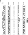
FIG. 14 is a flow chart of a method of manufacturing a tray for a tray table. - The trays described herein can prevent spilled liquids from spreading outside the tray surface and provide for quick and easy clean-up. The foregoing benefit as well as others, are achieved by a tray for a tray table that collects liquid spilled on a top surface of the tray in a replaceable absorbent pad positioned in a receptacle within the tray, and therefore reduces the risk of spilled liquid spreading over edges of the tray and dirtying the surrounding area and user of the tray table. The replaceable pad is easily inserted into and removed from the receptacle in the tray, and can include an indicator for indicating when the absorbent pad has reached maximum capacity and requires replacement.
- In the following detailed description and the drawing figures, illustrative embodiments of a
tray 10 for a tray table and methods for preventing a liquid spilled on atop surface 12 of atray 10 from spreading over anedge 14 of thetray 10 are described. The description is merely exemplary in nature and is not intended to limit the disclosed tray or the application and uses of the disclosed tray. It will be recognized by one skilled in the art that the present disclosure may be practiced in a variety of applications or environments and/or with other analogous or equivalent variations of the illustrative examples. For example, the concepts and teachings disclosed herein may be applied to a tray of the type used with tray tables on seatbacks in aircraft, trains and other vehicles, or any other type of portable table or surface upon which a liquid could spill. - It should be noted that those methods, procedures, components, or functions which are commonly known to persons of ordinary skill in the field of the disclosure are not described in detail herein. A person skilled in the art will appreciate that in the development of an actual embodiment, numerous implementation-specific decisions must be made to achieve the developer's specific goals, which will vary from one implementation to another. Moreover, it will be appreciated that such a development effort might be complex and time-consuming, but would nevertheless be a routine undertaking for those of ordinary skill in the art having the benefit of this disclosure.
- Referring to the drawings, the
tray 10 comprises acasing 16 having atop surface 12 with at least oneaperture 18 through thetop surface 12. Theaperture 18 acts as a drain for liquid that is spilled on thetop surface 12. Theaperture 18 may take any form including, without limitation, a round, square or rectangular shaped hole or slot. Theaperture 18 need not be covered, but may have a pervious or mesh cover placed over theaperture 18. Thecasing 16 may be made from any type of lightweight, moldable and sturdy material, such as aluminum, metal or plastic, and formed into a shape suitable for a particular use. For example, thetray 10 may have a generally rectangular shape and be used in a tray table that is pivotably and foldably attached to a seatback in an airplane or train, such that the tray table can be selectively folded down by a passenger seated in the immediately rearward seat. - Referring more particularly to
FIGS. 2-4 ,6-8 and10-12 , areceptacle 20 is positioned within thecasing 16 and below theaperture 18 in thetop surface 12, and configured to receive anabsorbent pad 22 that can be removably positioned in thereceptacle 20 below theaperture 18 to be in communication with thetop surface 12. Theabsorbent pad 22 is configured to absorb liquid that spills on thetop surface 12 and enters theaperture 18. Thereceptacle 20 extends under substantially anentire area 13 of thetop surface 12, and theabsorbent pad 22 substantially fills thereceptacle 20 such that theabsorbent pad 22 fills between about 25% to 80% of the volume of thereceptacle 20. Thecasing 16 has anopening 24 in aside 26 of thecasing 16 in communication with thereceptacle 20 that permits insertion and removal of theabsorbent pad 22 into and out of thereceptacle 20. As shown inFIGS. 2 and6 , alocking device 28 may optionally be included for maintaining theabsorbent pad 22 in thereceptacle 20. For example, apivotable bar 30 may be positioned on theside 26 of thecasing 16 to rotate about apivot point 32 positioned above or below theopening 24, such that thepivotable bar 30 is moveable between a horizontal position that permits entry of theabsorbent pad 22 and a vertical position that blocks theopening 24 and prevents theabsorbent pad 22 from being removed. - In use, it is desirable to use an
absorbent pad 22 that does not require frequent replacement, and can be used until theabsorbent pad 22 reaches its maximum capacity without leaking. Anabsorbent pad 22 comprising a superabsorbent material, such as a superabsorbent polymer (SAP) that can absorb and retain extremely large amounts of a liquid relative to its own mass, meets those goals. For example, in a 0.9% saline solution, a SAP may absorb about 50 times its weight, and in deionized and distilled water, a SAP may absorb about 300 times its weight. Superabsorbent polymer (SAP) is made from the polymerization of acrylic acid blended with sodium hydroxide in the presence of an initiator to form a poly-acrylic acid sodium salt (sometimes referred to as sodium polyacrylate). Commercial products based on SAP materials are often referred to as slush powder. Superabsorbent polymers also act as smell absorbers, which will prevent odors from the liquid absorbed therein from permeating from the SAP, and therefore extend the life of the SAP before replacement. Alternatively, an absorbent, but not superabsorbent, silica gel - a SiO2 based polymer - may be used instead of the SAP. - The state of the
absorbent pad 22 may be checked visually or by touch by sliding theabsorbent pad 22 out of thereceptacle 20. Alternatively, a visual indicator may be provided to assess the amount of liquid absorbed in theabsorbent pad 22 and indicate when theabsorbent pad 22 has reached its maximum capacity and should be replaced. For example, a piece of material that dissolves in water-based liquids may be positioned at a point that is located in the furthermost spot from theaperture 18. SAP material or Silica gel may be doped with a moisture indicator that gradually changes its color when it transitions from the anhydrous (dry) state to the hydrated (wet) state. Common indicators are cobalt chloride and methyl violet. Digital humidity meters may also be located in at least three different locations inside the absorber, and the measurements can be combined and presented on the visible side of absorber, for example with LEDs or a simple LCD display. All such indicators may be checked either by sliding theabsorbent pad 22 out of thereceptacle 20 or through anoptional window 34 through a bottom 36 of thecasing 16, as shown inFIG. 13 , positioned below theabsorbent pad 22. Thewindow 34 is covered with a clear plastic or glass covering 38 that permits visual inspection of theabsorbent pad 22. - It is also desirable to provide a
top surface 12 of thecasing 16 that repels a liquid spilled on the top surface 12 (and prevents the liquid from permeating into the top surface 12) to assist the liquid's movement toward theaperture 18 and into theabsorbent pad 22. One way to provide such a surface is to coat asuperhydrophobic coating 40 on thetop surface 12 of thecasing 16 such that thesuperhydrophobic coating 40 becomes a part of thetop surface 12. Asuperhydrophobic coating 40 is a nanoscopic surface layer that repels liquids. Droplets hitting thesuperhydrophobic coating 40 can fully rebound in the shape of a column or pancake and glide across thesuperhydrophobic coating 40. The property that is used for characterizing hydrophobicity of a material is the contact angle between a liquid droplet and the surface of material. Superhydrophobicity is achieved when the contact angle is above 150 degrees. Thetop surface 12 of thecasing 16 should therefore have a contact angle between a liquid droplet and thetop surface 12 greater than 150 degrees. Materials suitable for providing thesuperhydrophobic coating 40 are based on nano-composites like manganese oxide polystyrene, zinc oxide polystyrene, or silica nanoparticles. Examples of commercially-available materials suitable for thesuperhydrophobic coating 40 include, but are not limited to, NEVERWET® coatings available from NeverWet, LLC of Lancaster, Pennsylvania, superhydrophobic materials available from Aculon, Inc. of San Diego, California, and ULTRA EVER DRY® available from UltraTech International, Inc. of Jacksonville, Florida. - The geometry of the
top surface 12 of thecasing 16 can be arranged in many different configurations to achieve the desired result of guiding a spilled liquid toward the at least oneaperture 18 in the top surface such that the liquid is absorbed into theabsorbent pad 22 positioned in thereceptacle 20.Figures 1-4 show a first example of a surface geometry, wherein thetop surface 12 comprises threeelongated apertures 42. Theelongated apertures 42 extend linearly generally parallel to, and are positioned proximate to, arear side 44, aleft side 46, and aright side 48 of thecasing 16. Theelongated apertures 42 have a width of about 3-6 mm to limit the capillary effect that could block liquid from efficiently moving through theaperture 18 to theabsorbent pad 22, but other widths may be employed fordifferent tray 10 designs. In this example, thetop surface 12 of thecasing 16 is generally flat and has a raisededge 50 at afront side 52 of thecasing 16 that forms a barrier to prevent a liquid spilled on thetop surface 12 from dripping over the raisededge 50. The raisededge 50 also serves to guide the liquid toward theelongated apertures 42 in therear side 44, theleft side 46, and theright side 48 of thecasing 16. The raisededge 50 has an angle A relative to the plane B of thetop surface 12 up to 90 degrees, and preferably greater than 30 degrees. Although not shown in this example, thetop surface 12 may also include one or more sloped portions having a slope of about 0.5 to 1.0 degree that are sloped down toward theelongated apertures 42. The sloped portions provide a direction for a liquid to move along thetop surface 12, and may be used to reduce the number ofapertures 18 or the size of theapertures 18. - In other examples, the
top surface 12 of thecasing 16 has at least onesloped portion 54 sloped down toward and terminating at theaperture 18 through thetop surface 12. The slope S of the slopedportion 54 is slight, just enough to provide the guiding function without causing objects placed on the sloped portion to fall over, for example, the slopedportion 54 has a slope S of about 0.5 to 1.0 degree relative to ahorizontal plane 56 of thecasing 16.FIGS. 5-8 show atray 10 having atop surface 12 with a slopedportion 54 that is sloped from thefront side 52 of thecasing 16 down toward therear side 44 of the casing; that is the slope S of the slopedportion 54 causes thefront side 52 of thetop surface 12 to be at a higher level than therear side 44 of thetop surface 12. The slopedportion 54 terminates at theaperture 18 through thetop surface 12, which is configured in this example as a singleelongated aperture 42 extending linearly generally parallel to, and positioned proximate to, therear side 44 of thecasing 16, such that theelongated aperture 42 extends a substantial part of the width of therear side 44. The slope S of the slopedportion 54 guides a liquid spilled on thetop surface 12 toward theaperture 18 and into theabsorbent pad 22. The slopedportion 54 has a width at least as wide as the width of theelongated aperture 42. In this example, thetop surface 12 of thecasing 16 includes a first raisededge 50a at aleft side 46 of thecasing 16 and a second raisededge 50b at aright side 48 of thecasing 16 to form a barrier to prevent a liquid spilled on thetop surface 12 from dripping over theleft side 46 and theright side 48 of thecasing 16 and to further guide the liquid toward theelongated aperture 42. -
FIGS. 9-12 show another example of atray 10 having slopedportions 54 in thetop surface 12 of thecasing 16. In this example, theaperture 18 is configured as a round hole that is positioned proximate acenter 58 of thetop surface 12. The hole in thecenter 58 need not be round; it could be square, rectangular or any other shape. Thetop surface 12 has four slopedportions 54 extending from aright side 48, aleft side 46, arear side 44, and afront side 52 of thecasing 16 that all slope downward toward theaperture 18 in thecenter 58 of thetop surface 12. Thesloped portions 54 have a slope of about 0.5 to 1.0 degrees that causes thecenter 58 of thetop surface 12 to be at a lower level than all of the sides of thetop surface 12, and permits theaperture 18 to act as a central drain. The features described with respect toFIGS. 1-4 ,FIGS. 5-8 ,FIGS. 9-12 , andFIG. 13 can be combined in any number of ways that prevent a liquid from flowing over an edge of thetray 10 and/or to channel the liquid to theabsorbent pad 22 within thecasing 16. - Referring to
FIG. 14 , amethod 100 for making atray 10 for a tray table as shown inFigs. 1-13 that can prevent a liquid spilled on atop surface 12 of thetray 10 from spreading over anedge 14 of thetray 10 is provided. Instep 102, acasing 16 is formed having areceptacle 20 within thecasing 16 and atop surface 12 with at least oneaperture 18 through thetop surface 12 in communication with thereceptacle 20. Instep 104, during use, a removableabsorbent pad 22 is inserted into thereceptacle 20 below theaperture 18 to be in communication with thetop surface 12. As disclosed above, instep 106, theabsorbent pad 22 can be a superabsorbent material that can absorb and retain large amounts of a liquid relative to its own mass so that it quickly absorbs any spilled liquid on thetop surface 12 of thetray 10 and reduces the frequency of having to replace theabsorbent pad 22. Instep 108, asuperhydrophobic coating 40 can be coated on thetop surface 12 of thecasing 16 to provide a high degree of liquid repellency. Instep 110, thetop surface 12 can be configured to guide any liquid spilled on thetray 10 toward theaperture 18 through thetop surface 12 and into theabsorbent pad 22. - While the
tray 10 has been described with reference to various embodiments, it will be understood by those skilled in the art that various changes may be made and equivalents may be substituted for elements thereof without departing from the teachings herein. For example, and without limitation, the shape of thetray 10, the area of thetop surface 13, the angle A of the raisededge 50, and other elements may be adjusted to accommodate other design considerations. Thetray 10 may be manufactured and sold with or without the absorbent pad. - Further, the disclosure comprises embodiments according to the following Clauses:
- Clause 1. A tray for a tray table, the tray comprising: a casing having a top surface with at least one aperture through the top surface; and a receptacle within the casing positioned below the aperture in the top surface and configured to receive an absorbent pad that can be positioned within the receptacle below the aperture to be in communication with the top surface.
- Clause 2. The tray according to Clause 1, wherein the absorbent pad comprises a superabsorbent material.
-
Clause 3. The tray according to Clause 2, wherein the superabsorbent material comprises a superabsorbent polymer (SAP) that absorbs about 50 times to 300 times its weight. - Clause 4. The tray according to
Clause 3, wherein the SAP is made from a polymerization of acrylic acid blended with sodium hydroxide in the presence of an initiator to form a poly-acrylic acid sodium salt, such as a slush powder. - Clause 5. The tray according to
Clause 3 or 4, wherein the SAP acts as smell absorbers that prevents odors from a liquid absorbed therein from permeating from the SAP. - Clause 6. The tray according to Clause 1, wherein the absorbent pad comprises a silica gel, such as a SiO2 based polymer.
-
Clause 7. The tray according to any one of Clauses 1 to 6, wherein the absorbent pad comprises a visual indicator configured to indicate when the absorbent pad has reached a maximum capacity. -
Clause 8. The tray according toClause 7, wherein the visual indicator comprises a piece of material that dissolves in water-based liquids and is located in a furthermost spot from the aperture. - Clause 9. The tray according to
Clause 7, wherein the visual indicator comprises a moisture indicator that dopes a material of the absorbent pad, the moisture indicator configured to gradually change color when the moisture indicators transitions from an anhydrous or dry state to a hydrated or wet state. -
Clause 10. The tray according toClause 7, wherein the visual indicator comprises digital humidity meters. -
Clause 11. The tray according to any one of Clauses 1 to 10, further comprising a superhydrophobic coating on the top surface of the casing. -
Clause 12. The tray according to any one of Clauses 1 to 11, further comprising an opening in a side of the casing in communication with the receptacle that permits insertion and removal of the absorbent pad. -
Clause 13. The tray according toClause 12, further comprising a locking device for maintaining the absorbent pad in the receptacle. -
Clause 14. The tray according toClause - Clause 15. The tray according to
Clause 14, wherein the absorbent pad fills between about 25% to 80% of a volume of the receptacle. -
Clause 16. The tray according to any one of Clauses 1 to 15, further comprising a window through a bottom of the casing positioned below the absorbent pad that permits visual inspection of the absorbent pad. - Clause 17. The tray according to any one of Clauses 1 to 16, wherein the top surface comprises three elongated apertures, the elongated apertures positioned proximate a rear side, a left side, and a right side of the casing.
-
Clause 18. The tray according to Clause 17, wherein the top surface further comprises a raised edge at a front side of the casing that forms a barrier to prevent a liquid spilled on the top surface from dripping over the raised edge and to guide the liquid toward the elongated apertures in the rear side, the left side, and the right side. - Clause 19. The tray according to any one of Clauses 1 to 18, wherein the top surface comprises at least one sloped portion sloped down toward and terminating at the aperture through the top surface.
-
Clause 20. The tray according to Clause 19, wherein the top surface comprises an elongated aperture extending generally parallel to, and positioned proximate, a rear side of the casing. - Clause 21. The tray according to
Clause 20, wherein the top surface further comprises a first raised edge at a left side of the casing and a second raised edge at a right side of the casing that form a barrier to prevent a liquid spilled on the top surface from dripping over the left side and the right side of the casing and to guide the liquid toward the elongated aperture. -
Clause 22. The tray according to Clause 19, wherein the aperture is positioned proximate a center of the top surface, the top surface comprising four sloped portions extending from a right side, a left side, a rear side, and a front side of the casing down toward the aperture in the center of the top surface. - Clause 23. The tray according to any one of Clauses 19 to 22, wherein the sloped portion has a slope of about 0.5 to 1.0 degree.
-
Clause 24. The tray according to any one of Clauses 1 to 23, wherein the aperture acts as a drain for liquid that is spilled on the top surface. - Clause 25. The tray according to any one of Clauses 1 to 24, further comprising a pervious or mesh cover placed over the aperture.
-
Clause 26. The tray according to any one of Clauses 1 to 25, wherein the tray is pivotably and foldably attached to a seatback in an airplane or train as the tray table, such that the tray table can be selectively folded down by a passenger seated in an immediately rearward seat. - Clause 27. A method for making a tray for a tray table, the method comprising the step of: forming a casing having a receptacle within the casing and a top surface with at least one aperture through the top surface in communication with the receptacle; and configuring the receptacle to receive an absorbent pad that can be positioned within the receptacle below the aperture to be in communication with the top surface.
-
Clause 28. The method of Clause 27, further comprising forming the absorbent pad from a superabsorbent material. - Clause 29. The method of
Clause 27 or 28, further comprising coating the top surface of the casing with a superhydrophobic coating. -
Clause 30. The method of any one of Clauses 27 to 29, wherein the step of forming the casing further comprises forming an opening through a side of the casing in communication with the receptacle, such that the removable absorbent pad may be inserted and removed from the receptacle through the opening. - Clause 31. The method of
Clause 30, wherein the step of forming the casing further comprises providing a locking device proximate the opening for maintaining the absorbent pad in the receptacle. -
Clause 32. The method of any one of Clauses 27 to 31, wherein the step of forming the casing further comprises forming the top surface with at least one sloped portion sloped down toward and terminating at the aperture through the top surface. - In addition, many modifications may be made to adapt the concepts and reductions to practice disclosed herein to a particular situation. Accordingly, it is intended that all such modifications and variations be considered as within the spirit and scope of this disclosure, as defined in the following claims, and that the subject matter covered by the claims not be limited the disclosed embodiments. The process claims set forth hereinafter should not be construed to require that the steps recited therein be performed in the order in which they are recited or in alphabetical order (any alphabetical ordering in the claims is used solely for the purpose of referencing previously recited steps).
Claims (15)
- A tray (10) for a tray table, the tray comprising:a casing (16) having a top surface (12) with at least one aperture (18) through the top surface; anda receptacle (20) within the casing positioned below the aperture in the top surface and configured to receive an absorbent pad (22) that can be positioned within the receptacle below the aperture to be in communication with the top surface.
- The tray (10) according to claim 1, wherein the absorbent pad (22) comprises a superabsorbent material.
- The tray (10) according to claim 2, further comprising a superhydrophobic coating (40) on the top surface (12) of the casing (16).
- The tray (10) according to any one of claims 1 to 3, further comprising an opening (24) in a side (26) of the casing (16) in communication with the receptacle (20) that permits insertion and removal of the absorbent pad (22).
- The tray (10) according to any one of claims 1 to 4, wherein the top surface (12) comprises three elongated apertures (42), the elongated apertures positioned proximate a rear side (44), a left side (46), and a right side (48) of the casing (16), preferably wherein the top surface further comprises a raised edge (50) at a front side (52) of the casing that forms a barrier to prevent a liquid spilled on the top surface from dripping over the raised edge and to guide the liquid toward the elongated apertures in the rear side, the left side, and the right side.
- The tray (10) according to any one of claims 1 to 5, wherein the top surface (12) comprises at least one sloped portion (54) sloped down toward and terminating at the aperture (18) through the top surface.
- The tray (10) according to claim 6, wherein the top surface (12) comprises an elongated aperture (42) extending generally parallel to, and positioned proximate, a rear side (44) of the casing (16), preferably wherein the top surface further comprises a first raised edge (50a) at a left side (46) of the casing and a second raised edge (50b) at a right side (48) of the casing that form a barrier to prevent a liquid spilled on the top surface from dripping over the left side and the right side of the casing and to guide the liquid toward the elongated aperture.
- The tray (10) according to claim 6, wherein the aperture (18) is positioned proximate a center (58) of the top surface (12), the top surface comprising four sloped portions (54) extending from a right side (48), a left side (46), a rear side (44), and a front side (52) of the casing (16) down toward the aperture in the center of the top surface.
- The tray (10) according to any one of claims 1 to 8, wherein the tray is pivotably and foldably attached to a seatback in an airplane or train as the tray table, such that the tray table can be selectively folded down by a passenger seated in an immediately rearward seat.
- A method (100) for making a tray (10) for a tray table, the method comprising the step of:forming (102) a casing (16) having a receptacle (20) within the casing and a top surface (12) with at least one aperture (18) through the top surface in communication with the receptacle; andconfiguring the receptacle to receive (104) an absorbent pad (22) that can be positioned within the receptacle below the aperture to be in communication with the top surface.
- The method (100) of claim 10, further comprising forming (106) the absorbent pad (22) from a superabsorbent material.
- The method (100) of claim 11, further comprising coating (108) the top surface (12) of the casing (16) with a superhydrophobic coating (40).
- The method (100) of any one of claims 10 to 12, wherein the step of forming (102) the casing (16) further comprises forming an opening (24) through a side (26) of the casing in communication with the receptacle (20), such that the removable absorbent pad (22) may be inserted and removed from the receptacle through the opening.
- The method (100) of claim 13, wherein the step of forming (102) the casing (16) further comprises providing a locking device (28) proximate the opening (24) for maintaining the absorbent pad (22) in the receptacle (20).
- The method (100) of any one of claims 10 to 14, wherein the step of forming (102) the casing (16) further comprises forming the top surface (12) with at least one sloped portion (54) sloped down toward and terminating at the aperture (18) through the top surface.
Applications Claiming Priority (1)
| Application Number | Priority Date | Filing Date | Title |
|---|---|---|---|
| US15/408,601 US10517415B2 (en) | 2017-01-18 | 2017-01-18 | Tray table trays |
Publications (2)
| Publication Number | Publication Date |
|---|---|
| EP3351426A1 true EP3351426A1 (en) | 2018-07-25 |
| EP3351426B1 EP3351426B1 (en) | 2022-05-04 |
Family
ID=60021951
Family Applications (1)
| Application Number | Title | Priority Date | Filing Date |
|---|---|---|---|
| EP17194836.7A Not-in-force EP3351426B1 (en) | 2017-01-18 | 2017-10-04 | Tray table trays |
Country Status (5)
| Country | Link |
|---|---|
| US (2) | US10517415B2 (en) |
| EP (1) | EP3351426B1 (en) |
| CN (1) | CN108327739B (en) |
| BR (1) | BR102017025007B1 (en) |
| CA (1) | CA2983496C (en) |
Families Citing this family (7)
| Publication number | Priority date | Publication date | Assignee | Title |
|---|---|---|---|---|
| US20180295798A1 (en) * | 2017-04-13 | 2018-10-18 | Lyriel J. Jordan | Beverage Coaster with Integrated Plant Pot |
| CN111148491B (en) * | 2017-09-21 | 2023-04-07 | 宝洁公司 | Absorbent article |
| US20200242575A1 (en) | 2017-12-08 | 2020-07-30 | Talkbox, LLC | System and method for providing a discrete workspace |
| JP7797202B2 (en) | 2019-05-31 | 2026-01-13 | ザ プロクター アンド ギャンブル カンパニー | Absorbent article having waist gasket element |
| WO2021092606A1 (en) | 2019-11-04 | 2021-05-14 | The Procter & Gamble Company | Method and apparatus for bonding elastic parts under tension to an advancing carrier |
| US12364628B2 (en) | 2020-05-05 | 2025-07-22 | The Procter & Gamble Company | Absorbent articles including front and back waist panels with different stretch characteristics |
| CN115180155A (en) * | 2021-08-23 | 2022-10-14 | 上海田轩机械设备有限公司 | Foldable storage type head row dining table applicable to aviation seat |
Citations (6)
| Publication number | Priority date | Publication date | Assignee | Title |
|---|---|---|---|---|
| WO1990003320A1 (en) * | 1988-09-19 | 1990-04-05 | Clean-Pak, Inc. | Absorbent pad and method of constructing same |
| EP0495230A2 (en) * | 1990-12-27 | 1992-07-22 | Hoechst Aktiengesellschaft | Recyclable tray-like container with absorbent means |
| WO2007059187A1 (en) * | 2005-11-14 | 2007-05-24 | Pactiv Corporation | Container having internal reservoir |
| WO2009020805A1 (en) * | 2007-08-08 | 2009-02-12 | Meadwestvaco Corporation | Packaging tray with compartment |
| WO2012156173A1 (en) * | 2011-05-16 | 2012-11-22 | Unilever N.V. | Superhydrophobic coating |
| WO2013166067A1 (en) * | 2012-05-01 | 2013-11-07 | Pajic Nick | Tray table with electronic device support |
Family Cites Families (20)
| Publication number | Priority date | Publication date | Assignee | Title |
|---|---|---|---|---|
| US3963349A (en) * | 1974-08-27 | 1976-06-15 | American Hospital Supply Corporation | Method and apparatus for determining coagulation times |
| JPH0445879Y2 (en) * | 1987-06-19 | 1992-10-28 | ||
| US5908133A (en) * | 1994-09-08 | 1999-06-01 | Ropak Corporation | Container incorporating liquid draining means, and related method |
| IT1274530B (en) * | 1995-05-19 | 1997-07-17 | Sirap Gema Spa | PLASTIC TRAY FOR SUSCEPTIBLE FOODS TO RELEASE LIQUIDS |
| DE19528040A1 (en) * | 1995-07-31 | 1997-02-13 | Seafood Marketing Und Vertrieb | Food storage tray esp. for fresh fruit - has extra intermediate base above tray base, with fluid-absorbent material below it |
| DE19638239A1 (en) * | 1996-09-19 | 1998-03-26 | Linpac Technologie Gmbh | Bowl for holding liquid-producing food and beverages |
| US6036049A (en) * | 1997-04-17 | 2000-03-14 | Rehrig Pacific Company | Reusable produce crate |
| US6006903A (en) * | 1998-07-30 | 1999-12-28 | Cigar Savors Enterprises Llc | Cigar humidor |
| US5979646A (en) * | 1998-10-09 | 1999-11-09 | Strachan; Robert C. | Specialized tray system |
| US6135307A (en) * | 1998-10-29 | 2000-10-24 | Fahy; Joseph B. | Cereal sieve bowl |
| AU2003900386A0 (en) * | 2003-01-30 | 2003-02-13 | Amcor Limited | A baking tray |
| US6938774B2 (en) * | 2003-04-15 | 2005-09-06 | Entegris, Inc. | Tray carrier with ultraphobic surfaces |
| GR1004968B (en) | 2004-09-23 | 2005-09-08 | Weply Limited | Inflated polystyrene with the ability to absorb moisture internally, of a single-layer structure, without surface cover with membranes (non-laminated); products and method |
| CN2749830Y (en) * | 2004-10-29 | 2006-01-04 | 禹昌企业股份有限公司 | Perforated Absorbent Fresh Tray |
| US7395923B2 (en) * | 2005-09-09 | 2008-07-08 | Hsin-Hung Chou | Container having the function of absorbing blood and water of fresh food |
| RU2010152350A (en) * | 2008-05-22 | 2012-06-27 | Крайовак, Инк. (Us) | GAS-BARRIER AND ADSORPTIVE LIQUID CAPACITY FOR FOOD PACKAGING |
| US20110303679A1 (en) * | 2010-06-15 | 2011-12-15 | Tsung-I Yu | Drip dish |
| US20130098783A1 (en) * | 2011-10-20 | 2013-04-25 | Christian Hernandez | Apparatus for removing moisture from an electronic device |
| US9039099B2 (en) * | 2012-10-19 | 2015-05-26 | Phillip Sollami | Combination polycrystalline diamond bit and bit holder |
| TWM487900U (en) * | 2014-04-11 | 2014-10-11 | Liang-Fa Chou | Container structure |
-
2017
- 2017-01-18 US US15/408,601 patent/US10517415B2/en not_active Expired - Fee Related
- 2017-10-04 EP EP17194836.7A patent/EP3351426B1/en not_active Not-in-force
- 2017-10-24 CA CA2983496A patent/CA2983496C/en active Active
- 2017-11-22 BR BR102017025007-5A patent/BR102017025007B1/en not_active IP Right Cessation
- 2017-12-11 CN CN201711310289.7A patent/CN108327739B/en not_active Expired - Fee Related
-
2019
- 2019-12-03 US US16/701,745 patent/US11324346B2/en active Active
Patent Citations (6)
| Publication number | Priority date | Publication date | Assignee | Title |
|---|---|---|---|---|
| WO1990003320A1 (en) * | 1988-09-19 | 1990-04-05 | Clean-Pak, Inc. | Absorbent pad and method of constructing same |
| EP0495230A2 (en) * | 1990-12-27 | 1992-07-22 | Hoechst Aktiengesellschaft | Recyclable tray-like container with absorbent means |
| WO2007059187A1 (en) * | 2005-11-14 | 2007-05-24 | Pactiv Corporation | Container having internal reservoir |
| WO2009020805A1 (en) * | 2007-08-08 | 2009-02-12 | Meadwestvaco Corporation | Packaging tray with compartment |
| WO2012156173A1 (en) * | 2011-05-16 | 2012-11-22 | Unilever N.V. | Superhydrophobic coating |
| WO2013166067A1 (en) * | 2012-05-01 | 2013-11-07 | Pajic Nick | Tray table with electronic device support |
Also Published As
| Publication number | Publication date |
|---|---|
| US20180199743A1 (en) | 2018-07-19 |
| US20200100609A1 (en) | 2020-04-02 |
| US11324346B2 (en) | 2022-05-10 |
| CN108327739B (en) | 2020-08-14 |
| EP3351426B1 (en) | 2022-05-04 |
| BR102017025007A8 (en) | 2022-09-20 |
| BR102017025007B1 (en) | 2022-12-27 |
| CA2983496C (en) | 2022-04-12 |
| CN108327739A (en) | 2018-07-27 |
| BR102017025007A2 (en) | 2018-08-07 |
| CA2983496A1 (en) | 2018-07-18 |
| US10517415B2 (en) | 2019-12-31 |
Similar Documents
| Publication | Publication Date | Title |
|---|---|---|
| US11324346B2 (en) | Tray table trays | |
| US2861716A (en) | Drinking receptacle | |
| US4907775A (en) | Container holder | |
| WO2017067788A1 (en) | Beverage-making machine | |
| CA2774548A1 (en) | Wine aerator tower | |
| US5690138A (en) | Receptacle for a dripping spigot | |
| EP1172252A1 (en) | Retractable folding table | |
| CN207644224U (en) | A kind of anti-dumping reverse mould thermal insulation cup with automobile-used detent mechanism | |
| US10900948B2 (en) | Method for quantitating retail paper towel lint | |
| US6101977A (en) | Pet water dispenser | |
| CA2000902C (en) | Drink holder for automotive mini vans | |
| US20070011837A1 (en) | Dip stick wiper apparatus | |
| US20110232536A1 (en) | Multi-Functional Apparatus For Aiding Cleaning Of Edged Surfaces And Storage | |
| US20080277856A1 (en) | Universal chopping board system | |
| DE102022114329A1 (en) | Food preparation device, motor vehicle, and piece of furniture | |
| KR101070189B1 (en) | Alcohol degradable liquor glass for measuring amount of liquor | |
| CN209825802U (en) | A chopping board operating table with bucket | |
| KR200460217Y1 (en) | Adjustable Cup Holder for Several Cup Size | |
| CN217365285U (en) | Categorised dish of putting that fried food used | |
| CN216568946U (en) | Safe and harmless stainless steel dining car | |
| US20090285997A1 (en) | Paintbrush and edger holder | |
| CN110623426A (en) | Multifunctional desk capable of being obliquely moved | |
| CN202095943U (en) | Automatic water leaking glass kettle | |
| CN209595085U (en) | A kind of hotel's dining car | |
| US20120247507A1 (en) | Oil Cleaning Tool and Method of Use |
Legal Events
| Date | Code | Title | Description |
|---|---|---|---|
| PUAI | Public reference made under article 153(3) epc to a published international application that has entered the european phase |
Free format text: ORIGINAL CODE: 0009012 |
|
| STAA | Information on the status of an ep patent application or granted ep patent |
Free format text: STATUS: REQUEST FOR EXAMINATION WAS MADE |
|
| 17P | Request for examination filed |
Effective date: 20171004 |
|
| AK | Designated contracting states |
Kind code of ref document: A1 Designated state(s): AL AT BE BG CH CY CZ DE DK EE ES FI FR GB GR HR HU IE IS IT LI LT LU LV MC MK MT NL NO PL PT RO RS SE SI SK SM TR |
|
| AX | Request for extension of the european patent |
Extension state: BA ME |
|
| RBV | Designated contracting states (corrected) |
Designated state(s): AL AT BE BG CH CY CZ DE DK EE ES FI FR GB GR HR HU IE IS IT LI LT LU LV MC MK MT NL NO PL PT RO RS SE SI SK SM TR |
|
| GRAP | Despatch of communication of intention to grant a patent |
Free format text: ORIGINAL CODE: EPIDOSNIGR1 |
|
| STAA | Information on the status of an ep patent application or granted ep patent |
Free format text: STATUS: GRANT OF PATENT IS INTENDED |
|
| INTG | Intention to grant announced |
Effective date: 20210813 |
|
| GRAJ | Information related to disapproval of communication of intention to grant by the applicant or resumption of examination proceedings by the epo deleted |
Free format text: ORIGINAL CODE: EPIDOSDIGR1 |
|
| STAA | Information on the status of an ep patent application or granted ep patent |
Free format text: STATUS: REQUEST FOR EXAMINATION WAS MADE |
|
| INTC | Intention to grant announced (deleted) | ||
| GRAP | Despatch of communication of intention to grant a patent |
Free format text: ORIGINAL CODE: EPIDOSNIGR1 |
|
| STAA | Information on the status of an ep patent application or granted ep patent |
Free format text: STATUS: GRANT OF PATENT IS INTENDED |
|
| INTG | Intention to grant announced |
Effective date: 20211217 |
|
| GRAS | Grant fee paid |
Free format text: ORIGINAL CODE: EPIDOSNIGR3 |
|
| GRAA | (expected) grant |
Free format text: ORIGINAL CODE: 0009210 |
|
| STAA | Information on the status of an ep patent application or granted ep patent |
Free format text: STATUS: THE PATENT HAS BEEN GRANTED |
|
| AK | Designated contracting states |
Kind code of ref document: B1 Designated state(s): AL AT BE BG CH CY CZ DE DK EE ES FI FR GB GR HR HU IE IS IT LI LT LU LV MC MK MT NL NO PL PT RO RS SE SI SK SM TR |
|
| REG | Reference to a national code |
Ref country code: GB Ref legal event code: FG4D |
|
| REG | Reference to a national code |
Ref country code: CH Ref legal event code: EP |
|
| REG | Reference to a national code |
Ref country code: AT Ref legal event code: REF Ref document number: 1488720 Country of ref document: AT Kind code of ref document: T Effective date: 20220515 |
|
| REG | Reference to a national code |
Ref country code: IE Ref legal event code: FG4D Ref country code: DE Ref legal event code: R096 Ref document number: 602017056817 Country of ref document: DE |
|
| REG | Reference to a national code |
Ref country code: LT Ref legal event code: MG9D |
|
| REG | Reference to a national code |
Ref country code: NL Ref legal event code: MP Effective date: 20220504 |
|
| REG | Reference to a national code |
Ref country code: AT Ref legal event code: MK05 Ref document number: 1488720 Country of ref document: AT Kind code of ref document: T Effective date: 20220504 |
|
| PG25 | Lapsed in a contracting state [announced via postgrant information from national office to epo] |
Ref country code: SE Free format text: LAPSE BECAUSE OF FAILURE TO SUBMIT A TRANSLATION OF THE DESCRIPTION OR TO PAY THE FEE WITHIN THE PRESCRIBED TIME-LIMIT Effective date: 20220504 Ref country code: PT Free format text: LAPSE BECAUSE OF FAILURE TO SUBMIT A TRANSLATION OF THE DESCRIPTION OR TO PAY THE FEE WITHIN THE PRESCRIBED TIME-LIMIT Effective date: 20220905 Ref country code: NO Free format text: LAPSE BECAUSE OF FAILURE TO SUBMIT A TRANSLATION OF THE DESCRIPTION OR TO PAY THE FEE WITHIN THE PRESCRIBED TIME-LIMIT Effective date: 20220804 Ref country code: NL Free format text: LAPSE BECAUSE OF FAILURE TO SUBMIT A TRANSLATION OF THE DESCRIPTION OR TO PAY THE FEE WITHIN THE PRESCRIBED TIME-LIMIT Effective date: 20220504 Ref country code: LT Free format text: LAPSE BECAUSE OF FAILURE TO SUBMIT A TRANSLATION OF THE DESCRIPTION OR TO PAY THE FEE WITHIN THE PRESCRIBED TIME-LIMIT Effective date: 20220504 Ref country code: HR Free format text: LAPSE BECAUSE OF FAILURE TO SUBMIT A TRANSLATION OF THE DESCRIPTION OR TO PAY THE FEE WITHIN THE PRESCRIBED TIME-LIMIT Effective date: 20220504 Ref country code: GR Free format text: LAPSE BECAUSE OF FAILURE TO SUBMIT A TRANSLATION OF THE DESCRIPTION OR TO PAY THE FEE WITHIN THE PRESCRIBED TIME-LIMIT Effective date: 20220805 Ref country code: FI Free format text: LAPSE BECAUSE OF FAILURE TO SUBMIT A TRANSLATION OF THE DESCRIPTION OR TO PAY THE FEE WITHIN THE PRESCRIBED TIME-LIMIT Effective date: 20220504 Ref country code: ES Free format text: LAPSE BECAUSE OF FAILURE TO SUBMIT A TRANSLATION OF THE DESCRIPTION OR TO PAY THE FEE WITHIN THE PRESCRIBED TIME-LIMIT Effective date: 20220504 Ref country code: BG Free format text: LAPSE BECAUSE OF FAILURE TO SUBMIT A TRANSLATION OF THE DESCRIPTION OR TO PAY THE FEE WITHIN THE PRESCRIBED TIME-LIMIT Effective date: 20220804 Ref country code: AT Free format text: LAPSE BECAUSE OF FAILURE TO SUBMIT A TRANSLATION OF THE DESCRIPTION OR TO PAY THE FEE WITHIN THE PRESCRIBED TIME-LIMIT Effective date: 20220504 |
|
| PG25 | Lapsed in a contracting state [announced via postgrant information from national office to epo] |
Ref country code: RS Free format text: LAPSE BECAUSE OF FAILURE TO SUBMIT A TRANSLATION OF THE DESCRIPTION OR TO PAY THE FEE WITHIN THE PRESCRIBED TIME-LIMIT Effective date: 20220504 Ref country code: PL Free format text: LAPSE BECAUSE OF FAILURE TO SUBMIT A TRANSLATION OF THE DESCRIPTION OR TO PAY THE FEE WITHIN THE PRESCRIBED TIME-LIMIT Effective date: 20220504 Ref country code: LV Free format text: LAPSE BECAUSE OF FAILURE TO SUBMIT A TRANSLATION OF THE DESCRIPTION OR TO PAY THE FEE WITHIN THE PRESCRIBED TIME-LIMIT Effective date: 20220504 Ref country code: IS Free format text: LAPSE BECAUSE OF FAILURE TO SUBMIT A TRANSLATION OF THE DESCRIPTION OR TO PAY THE FEE WITHIN THE PRESCRIBED TIME-LIMIT Effective date: 20220904 |
|
| PGFP | Annual fee paid to national office [announced via postgrant information from national office to epo] |
Ref country code: FR Payment date: 20221025 Year of fee payment: 6 |
|
| PG25 | Lapsed in a contracting state [announced via postgrant information from national office to epo] |
Ref country code: SM Free format text: LAPSE BECAUSE OF FAILURE TO SUBMIT A TRANSLATION OF THE DESCRIPTION OR TO PAY THE FEE WITHIN THE PRESCRIBED TIME-LIMIT Effective date: 20220504 Ref country code: SK Free format text: LAPSE BECAUSE OF FAILURE TO SUBMIT A TRANSLATION OF THE DESCRIPTION OR TO PAY THE FEE WITHIN THE PRESCRIBED TIME-LIMIT Effective date: 20220504 Ref country code: RO Free format text: LAPSE BECAUSE OF FAILURE TO SUBMIT A TRANSLATION OF THE DESCRIPTION OR TO PAY THE FEE WITHIN THE PRESCRIBED TIME-LIMIT Effective date: 20220504 Ref country code: EE Free format text: LAPSE BECAUSE OF FAILURE TO SUBMIT A TRANSLATION OF THE DESCRIPTION OR TO PAY THE FEE WITHIN THE PRESCRIBED TIME-LIMIT Effective date: 20220504 Ref country code: DK Free format text: LAPSE BECAUSE OF FAILURE TO SUBMIT A TRANSLATION OF THE DESCRIPTION OR TO PAY THE FEE WITHIN THE PRESCRIBED TIME-LIMIT Effective date: 20220504 Ref country code: CZ Free format text: LAPSE BECAUSE OF FAILURE TO SUBMIT A TRANSLATION OF THE DESCRIPTION OR TO PAY THE FEE WITHIN THE PRESCRIBED TIME-LIMIT Effective date: 20220504 |
|
| PGFP | Annual fee paid to national office [announced via postgrant information from national office to epo] |
Ref country code: GB Payment date: 20221027 Year of fee payment: 6 Ref country code: DE Payment date: 20221027 Year of fee payment: 6 |
|
| REG | Reference to a national code |
Ref country code: DE Ref legal event code: R097 Ref document number: 602017056817 Country of ref document: DE |
|
| PLBE | No opposition filed within time limit |
Free format text: ORIGINAL CODE: 0009261 |
|
| STAA | Information on the status of an ep patent application or granted ep patent |
Free format text: STATUS: NO OPPOSITION FILED WITHIN TIME LIMIT |
|
| RAP4 | Party data changed (patent owner data changed or rights of a patent transferred) |
Owner name: THE BOEING COMPANY |
|
| PG25 | Lapsed in a contracting state [announced via postgrant information from national office to epo] |
Ref country code: AL Free format text: LAPSE BECAUSE OF FAILURE TO SUBMIT A TRANSLATION OF THE DESCRIPTION OR TO PAY THE FEE WITHIN THE PRESCRIBED TIME-LIMIT Effective date: 20220504 |
|
| 26N | No opposition filed |
Effective date: 20230207 |
|
| PG25 | Lapsed in a contracting state [announced via postgrant information from national office to epo] |
Ref country code: SI Free format text: LAPSE BECAUSE OF FAILURE TO SUBMIT A TRANSLATION OF THE DESCRIPTION OR TO PAY THE FEE WITHIN THE PRESCRIBED TIME-LIMIT Effective date: 20220504 Ref country code: MC Free format text: LAPSE BECAUSE OF FAILURE TO SUBMIT A TRANSLATION OF THE DESCRIPTION OR TO PAY THE FEE WITHIN THE PRESCRIBED TIME-LIMIT Effective date: 20220504 |
|
| REG | Reference to a national code |
Ref country code: CH Ref legal event code: PL |
|
| REG | Reference to a national code |
Ref country code: BE Ref legal event code: MM Effective date: 20221031 |
|
| PG25 | Lapsed in a contracting state [announced via postgrant information from national office to epo] |
Ref country code: LU Free format text: LAPSE BECAUSE OF NON-PAYMENT OF DUE FEES Effective date: 20221004 |
|
| PG25 | Lapsed in a contracting state [announced via postgrant information from national office to epo] |
Ref country code: LI Free format text: LAPSE BECAUSE OF NON-PAYMENT OF DUE FEES Effective date: 20221031 Ref country code: CH Free format text: LAPSE BECAUSE OF NON-PAYMENT OF DUE FEES Effective date: 20221031 |
|
| PG25 | Lapsed in a contracting state [announced via postgrant information from national office to epo] |
Ref country code: BE Free format text: LAPSE BECAUSE OF NON-PAYMENT OF DUE FEES Effective date: 20221031 |
|
| PG25 | Lapsed in a contracting state [announced via postgrant information from national office to epo] |
Ref country code: IE Free format text: LAPSE BECAUSE OF NON-PAYMENT OF DUE FEES Effective date: 20221004 |
|
| PG25 | Lapsed in a contracting state [announced via postgrant information from national office to epo] |
Ref country code: IT Free format text: LAPSE BECAUSE OF FAILURE TO SUBMIT A TRANSLATION OF THE DESCRIPTION OR TO PAY THE FEE WITHIN THE PRESCRIBED TIME-LIMIT Effective date: 20220504 |
|
| PG25 | Lapsed in a contracting state [announced via postgrant information from national office to epo] |
Ref country code: HU Free format text: LAPSE BECAUSE OF FAILURE TO SUBMIT A TRANSLATION OF THE DESCRIPTION OR TO PAY THE FEE WITHIN THE PRESCRIBED TIME-LIMIT; INVALID AB INITIO Effective date: 20171004 |
|
| PG25 | Lapsed in a contracting state [announced via postgrant information from national office to epo] |
Ref country code: CY Free format text: LAPSE BECAUSE OF FAILURE TO SUBMIT A TRANSLATION OF THE DESCRIPTION OR TO PAY THE FEE WITHIN THE PRESCRIBED TIME-LIMIT Effective date: 20220504 |
|
| REG | Reference to a national code |
Ref country code: DE Ref legal event code: R119 Ref document number: 602017056817 Country of ref document: DE |
|
| PG25 | Lapsed in a contracting state [announced via postgrant information from national office to epo] |
Ref country code: MK Free format text: LAPSE BECAUSE OF FAILURE TO SUBMIT A TRANSLATION OF THE DESCRIPTION OR TO PAY THE FEE WITHIN THE PRESCRIBED TIME-LIMIT Effective date: 20220504 |
|
| GBPC | Gb: european patent ceased through non-payment of renewal fee |
Effective date: 20231004 |
|
| PG25 | Lapsed in a contracting state [announced via postgrant information from national office to epo] |
Ref country code: GB Free format text: LAPSE BECAUSE OF NON-PAYMENT OF DUE FEES Effective date: 20231004 |
|
| PG25 | Lapsed in a contracting state [announced via postgrant information from national office to epo] |
Ref country code: GB Free format text: LAPSE BECAUSE OF NON-PAYMENT OF DUE FEES Effective date: 20231004 Ref country code: FR Free format text: LAPSE BECAUSE OF NON-PAYMENT OF DUE FEES Effective date: 20231031 Ref country code: DE Free format text: LAPSE BECAUSE OF NON-PAYMENT OF DUE FEES Effective date: 20240501 |
|
| PG25 | Lapsed in a contracting state [announced via postgrant information from national office to epo] |
Ref country code: MT Free format text: LAPSE BECAUSE OF FAILURE TO SUBMIT A TRANSLATION OF THE DESCRIPTION OR TO PAY THE FEE WITHIN THE PRESCRIBED TIME-LIMIT Effective date: 20220504 |
|
| PG25 | Lapsed in a contracting state [announced via postgrant information from national office to epo] |
Ref country code: BG Free format text: LAPSE BECAUSE OF FAILURE TO SUBMIT A TRANSLATION OF THE DESCRIPTION OR TO PAY THE FEE WITHIN THE PRESCRIBED TIME-LIMIT Effective date: 20220504 |
|
| PG25 | Lapsed in a contracting state [announced via postgrant information from national office to epo] |
Ref country code: BG Free format text: LAPSE BECAUSE OF FAILURE TO SUBMIT A TRANSLATION OF THE DESCRIPTION OR TO PAY THE FEE WITHIN THE PRESCRIBED TIME-LIMIT Effective date: 20220504 |
|
| PG25 | Lapsed in a contracting state [announced via postgrant information from national office to epo] |
Ref country code: TR Free format text: LAPSE BECAUSE OF FAILURE TO SUBMIT A TRANSLATION OF THE DESCRIPTION OR TO PAY THE FEE WITHIN THE PRESCRIBED TIME-LIMIT Effective date: 20220504 |