EP3351279A1 - Drug delivery device - Google Patents
Drug delivery device Download PDFInfo
- Publication number
- EP3351279A1 EP3351279A1 EP17152455.6A EP17152455A EP3351279A1 EP 3351279 A1 EP3351279 A1 EP 3351279A1 EP 17152455 A EP17152455 A EP 17152455A EP 3351279 A1 EP3351279 A1 EP 3351279A1
- Authority
- EP
- European Patent Office
- Prior art keywords
- drug delivery
- delivery device
- cap
- needle
- housing
- Prior art date
- Legal status (The legal status is an assumption and is not a legal conclusion. Google has not performed a legal analysis and makes no representation as to the accuracy of the status listed.)
- Ceased
Links
Images



Classifications
-
- A—HUMAN NECESSITIES
- A61—MEDICAL OR VETERINARY SCIENCE; HYGIENE
- A61M—DEVICES FOR INTRODUCING MEDIA INTO, OR ONTO, THE BODY; DEVICES FOR TRANSDUCING BODY MEDIA OR FOR TAKING MEDIA FROM THE BODY; DEVICES FOR PRODUCING OR ENDING SLEEP OR STUPOR
- A61M5/00—Devices for bringing media into the body in a subcutaneous, intra-vascular or intramuscular way; Accessories therefor, e.g. filling or cleaning devices, arm-rests
- A61M5/178—Syringes
- A61M5/31—Details
- A61M5/3129—Syringe barrels
- A61M5/3137—Specially designed finger grip means, e.g. for easy manipulation of the syringe rod
-
- A—HUMAN NECESSITIES
- A61—MEDICAL OR VETERINARY SCIENCE; HYGIENE
- A61M—DEVICES FOR INTRODUCING MEDIA INTO, OR ONTO, THE BODY; DEVICES FOR TRANSDUCING BODY MEDIA OR FOR TAKING MEDIA FROM THE BODY; DEVICES FOR PRODUCING OR ENDING SLEEP OR STUPOR
- A61M5/00—Devices for bringing media into the body in a subcutaneous, intra-vascular or intramuscular way; Accessories therefor, e.g. filling or cleaning devices, arm-rests
- A61M5/002—Packages specially adapted therefor, e.g. for syringes or needles, kits for diabetics
-
- A—HUMAN NECESSITIES
- A61—MEDICAL OR VETERINARY SCIENCE; HYGIENE
- A61M—DEVICES FOR INTRODUCING MEDIA INTO, OR ONTO, THE BODY; DEVICES FOR TRANSDUCING BODY MEDIA OR FOR TAKING MEDIA FROM THE BODY; DEVICES FOR PRODUCING OR ENDING SLEEP OR STUPOR
- A61M5/00—Devices for bringing media into the body in a subcutaneous, intra-vascular or intramuscular way; Accessories therefor, e.g. filling or cleaning devices, arm-rests
- A61M5/178—Syringes
- A61M5/20—Automatic syringes, e.g. with automatically actuated piston rod, with automatic needle injection, filling automatically
-
- A—HUMAN NECESSITIES
- A61—MEDICAL OR VETERINARY SCIENCE; HYGIENE
- A61M—DEVICES FOR INTRODUCING MEDIA INTO, OR ONTO, THE BODY; DEVICES FOR TRANSDUCING BODY MEDIA OR FOR TAKING MEDIA FROM THE BODY; DEVICES FOR PRODUCING OR ENDING SLEEP OR STUPOR
- A61M5/00—Devices for bringing media into the body in a subcutaneous, intra-vascular or intramuscular way; Accessories therefor, e.g. filling or cleaning devices, arm-rests
- A61M5/178—Syringes
- A61M5/31—Details
- A61M5/32—Needles; Details of needles pertaining to their connection with syringe or hub; Accessories for bringing the needle into, or holding the needle on, the body; Devices for protection of needles
- A61M5/3202—Devices for protection of the needle before use, e.g. caps
-
- A—HUMAN NECESSITIES
- A61—MEDICAL OR VETERINARY SCIENCE; HYGIENE
- A61M—DEVICES FOR INTRODUCING MEDIA INTO, OR ONTO, THE BODY; DEVICES FOR TRANSDUCING BODY MEDIA OR FOR TAKING MEDIA FROM THE BODY; DEVICES FOR PRODUCING OR ENDING SLEEP OR STUPOR
- A61M5/00—Devices for bringing media into the body in a subcutaneous, intra-vascular or intramuscular way; Accessories therefor, e.g. filling or cleaning devices, arm-rests
- A61M5/178—Syringes
- A61M5/20—Automatic syringes, e.g. with automatically actuated piston rod, with automatic needle injection, filling automatically
- A61M2005/2006—Having specific accessories
- A61M2005/2013—Having specific accessories triggering of discharging means by contact of injector with patient body
-
- A—HUMAN NECESSITIES
- A61—MEDICAL OR VETERINARY SCIENCE; HYGIENE
- A61M—DEVICES FOR INTRODUCING MEDIA INTO, OR ONTO, THE BODY; DEVICES FOR TRANSDUCING BODY MEDIA OR FOR TAKING MEDIA FROM THE BODY; DEVICES FOR PRODUCING OR ENDING SLEEP OR STUPOR
- A61M5/00—Devices for bringing media into the body in a subcutaneous, intra-vascular or intramuscular way; Accessories therefor, e.g. filling or cleaning devices, arm-rests
- A61M5/178—Syringes
- A61M5/31—Details
- A61M5/3129—Syringe barrels
- A61M5/3137—Specially designed finger grip means, e.g. for easy manipulation of the syringe rod
- A61M2005/3139—Finger grips not integrally formed with the syringe barrel, e.g. using adapter with finger grips
-
- A—HUMAN NECESSITIES
- A61—MEDICAL OR VETERINARY SCIENCE; HYGIENE
- A61M—DEVICES FOR INTRODUCING MEDIA INTO, OR ONTO, THE BODY; DEVICES FOR TRANSDUCING BODY MEDIA OR FOR TAKING MEDIA FROM THE BODY; DEVICES FOR PRODUCING OR ENDING SLEEP OR STUPOR
- A61M2205/00—General characteristics of the apparatus
- A61M2205/58—Means for facilitating use, e.g. by people with impaired vision
- A61M2205/583—Means for facilitating use, e.g. by people with impaired vision by visual feedback
-
- A—HUMAN NECESSITIES
- A61—MEDICAL OR VETERINARY SCIENCE; HYGIENE
- A61M—DEVICES FOR INTRODUCING MEDIA INTO, OR ONTO, THE BODY; DEVICES FOR TRANSDUCING BODY MEDIA OR FOR TAKING MEDIA FROM THE BODY; DEVICES FOR PRODUCING OR ENDING SLEEP OR STUPOR
- A61M2205/00—General characteristics of the apparatus
- A61M2205/58—Means for facilitating use, e.g. by people with impaired vision
- A61M2205/586—Ergonomic details therefor, e.g. specific ergonomics for left or right-handed users
-
- A—HUMAN NECESSITIES
- A61—MEDICAL OR VETERINARY SCIENCE; HYGIENE
- A61M—DEVICES FOR INTRODUCING MEDIA INTO, OR ONTO, THE BODY; DEVICES FOR TRANSDUCING BODY MEDIA OR FOR TAKING MEDIA FROM THE BODY; DEVICES FOR PRODUCING OR ENDING SLEEP OR STUPOR
- A61M5/00—Devices for bringing media into the body in a subcutaneous, intra-vascular or intramuscular way; Accessories therefor, e.g. filling or cleaning devices, arm-rests
- A61M5/50—Devices for bringing media into the body in a subcutaneous, intra-vascular or intramuscular way; Accessories therefor, e.g. filling or cleaning devices, arm-rests having means for preventing re-use, or for indicating if defective, used, tampered with or unsterile
- A61M5/5086—Devices for bringing media into the body in a subcutaneous, intra-vascular or intramuscular way; Accessories therefor, e.g. filling or cleaning devices, arm-rests having means for preventing re-use, or for indicating if defective, used, tampered with or unsterile for indicating if defective, used, tampered with or unsterile
Definitions
- the disclosure generally relates to a drug delivery device. More particularly, the disclosure relates to an emergency pack for use with a drug delivery device.
- drug delivery devices comprise a housing or a shell in a shape of a pen which holds a drug cartridge or a drug container or a pre-filled syringe.
- Some drugs e.g. emergency drugs like glucagon, are required in small quantities and have special requirements for a fast handling and assistance, in particular for a fast preparation, e.g. opening of the drug delivery device.
- the present disclosure meets the foregoing need by providing a drug delivery device according to claim 1.
- a drug delivery device comprises at least a housing, a drug container with a needle and a cap, wherein the housing has an inner surface forming a cavity configured to retain the drug container, wherein the cap being configured to be releasably connected to the housing, in particular at a front end of the device, and wherein a back end of the device opposite to the front end directed to the cap comprises a gripping lug axially protruding from the back end of the device.
- the housing and the cap are releasably interconnected with each other to encapsulate the drug container.
- the device is easy to handle.
- the gripping lug may comprise an eyelet or finger loop configured to be gripped by a finger of a user, in particular by index or middle finger.
- the gripping lug is configured such that a user easily knows how to pull out or open the drug delivery device. Further the gripping lug is configured such that, after a user removed the cap, he still holds the device in the hand.
- the gripping lug can potentially be used on all kind of drug delivery devices like pre-filled syringes, auto-injectors or pen-injectors.
- the gripping lug has an inner surface forming a cavity configured to be assembled onto the back end of the housing.
- the cavity comprises a form, shape and/or size corresponding to the form, shape and size of the respective back end of the drug delivery device.
- the gripping lug is hold on to the back end of the housing by at least one of a force-fit connection and form-fit connection.
- the gripping lug comprises a retainer configured to be fixed onto the back end of the device, e.g. the housing.
- the retainer is formed on the inner surface of the gripping lug.
- the retainer comprises at least one locking hook radially extending from the inner surface.
- the retainer comprises a plurality of locking hooks all-round protruded and bevelled locking hooks which grab into the outer surface of the housing of the drug delivery device.
- the gripping lug may be attached onto different kind of drug delivery devices.
- the cap has a length which corresponds with the length of the housing.
- the cap has such a long length that it substantially full covers the drug delivery device, in particular the housing over its entire length including its distal or front end and the needle. Only a proximal end or the back end of the drug delivery device extends from the cap. This proximal end or back end of the drug delivery device is covered by the gripping lug.
- the cap and the device, in particular the housing comprise corresponding crimp interfaces.
- the cap is releasably coupled to a device, in particular to its housing.
- the needle sleeve may comprise a marker indicating the front end or distal end of the device.
- the needle sleeve may comprise an opening, for instance a triangular opening. The triangular opening points in the direction where the needle will project from the needle sleeve.
- the needle sleeve may comprise triangular openings on three sides of the sheath. Alternatively the needle sleeve may comprise two or four or more triangular openings.
- the cap comprises a shield grabber connecting the front cap to an outer surface of a needle shield, in particular a so-called rigid needle shield (RNS shield) covering the needle.
- RNS shield rigid needle shield
- the needle shield usually made from rubber which seals and covers the needle and the drug container from ambient.
- RNS shield rigid needle shield
- Such an integrated shield grabber inside the cap holds the rigid needle shield in an assembled state of the drug delivery device.
- removing of the cap will also remove the needle shield from the needle and make the drug delivery device ready to be used. This reduces handling steps for preparation of the drug delivery device.
- the shield grabber is provided with an inner hook element configured and arranged to hook on to an outer surface of the needle shield.
- the shield grabber and the needle shield comprise corresponding crimp features to fixedly hold the shield grabber and the needle shield together, in particular during removing of the cap as well as of the needle shield from the drug delivery device, in particular away from the needle.
- the disclosure provides a drug delivery device with a container or a syringe which is prefilled with a drug, in particular an emergency drug, e.g. an allergic drug or a diabetic drug, e.g. hypoglycemia.
- a drug in particular an emergency drug, e.g. an allergic drug or a diabetic drug, e.g. hypoglycemia.
- the drug delivery device is for instance an auto-injector, a pen-injector or a syringe.
- the drug delivery device comprises a piston which slides inside the container to inject the drug. Additionally, the drug delivery device comprises actuator means for automatically injecting a patient with said drug.
- the disclosure further provides an emergency pack comprising the above described drug delivery device.
- an outer surface of the emergency pack in particular of the housing or the outer cap, is configured in at least one parameter such that a specific drug contained within the drug delivery device may be quickly and easily identified by a person.
- the outer surface of the housing or the outer cap is coloured, e.g. is coloured in orange, red or yellow.
- the outer surface may comprise a shape or form which allows a fast and easy identification of the specific drug contained within the drug delivery device.
- the outer surface may comprise a pen-shape.
- the drug delivery device may be configured to inject a medicament into a patient.
- delivery could be sub-cutaneous, intra-muscular, or intravenous.
- a device could be operated by a patient or care-giver, such as a nurse or physician, and can include various types of safety syringe, pen-injector, or auto-injector.
- the device can include a cartridge-based system that requires piercing a sealed ampule before use. Volumes of medicament delivered with these various devices can range from about 0.5 ml to about 2 ml.
- Yet another device can include a large volume device (“LVD”) or patch pump, configured to adhere to a patient's skin for a period of time (e.g., about 5, 15, 30, 60, or 120 minutes) to deliver a "large" volume of medicament (typically about 2 ml to about 5 ml).
- a large volume device typically about 5 ml to about 5 ml.
- the presently described devices may also be customized in order to operate within required specifications.
- the device may be customized to inject a medicament within a certain time period (e.g., about 3 to about 20 seconds for auto-injectors, and about 10 minutes to about 60 minutes for an LVD).
- Other specifications can include a low or minimal level of discomfort, or to certain conditions related to human factors, shelf-life, expiry, biocompatibility, environmental considerations, etc. Such variations can arise due to various factors, such as, for example, a drug ranging in viscosity from about 3 cP to about 50 cP. Consequently, a drug delivery device will often include a hollow needle ranging from about 25 to about 31 Gauge in size. Common sizes are 27 and 29 Gauge.
- the delivery devices described herein can also include one or more automated functions. For example, one or more of needle insertion, medicament injection, and needle retraction can be automated. Energy for one or more automation steps can be provided by one or more energy sources. Energy sources can include, for example, mechanical, pneumatic, chemical, or electrical energy. For example, mechanical energy sources can include springs, levers, elastomers, or other mechanical mechanisms to store or release energy. One or more energy sources can be combined into a single device. Devices can further include gears, valves, or other mechanisms to convert energy into movement of one or more components of a device.
- the one or more automated functions of an auto-injector may be activated via an activation mechanism.
- an activation mechanism can include one or more of a button, a lever, a needle sleeve, or other activation component.
- Activation may be a one-step or multi-step process. That is, a user may need to activate one or more activation mechanism in order to cause the automated function. For example, a user may depress a needle sleeve against their body in order to cause injection of a medicament. In other devices, a user may be required to depress a button and retract a needle shield in order to cause injection.
- an activation sequence may activate at least two of needle insertion, medicament injection, and needle retraction. Some devices may also require a specific sequence of steps to cause the one or more automated functions to occur. Other devices may operate with sequence independent steps.
- Some delivery devices can include one or more functions of a safety syringe, pen-injector, or auto-injector.
- a delivery device could include a mechanical energy source configured to automatically inject a medicament (as typically found in an auto-injector) and a dose setting mechanism (as typically found in a pen-injector).
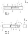
- an exemplary drug delivery device 10 is shown in Figures 1A and 1 B.
- Device 10 is configured to inject a medicament into a patient's body.
- Device 10 includes a housing 11 which typically contains a reservoir containing the medicament to be injected (e.g., a syringe or a container) and the components required to facilitate one or more steps of the delivery process.
- a reservoir containing the medicament to be injected e.g., a syringe or a container
- the components required to facilitate one or more steps of the delivery process e.g., a syringe or a container
- Device 10 can also include a cap assembly 12 that can be detachably mounted to the housing 11, in particular on a distal or front end D of the device 10. Typically, a user must remove cap assembly or cap 12 from housing 11 before device 10 can be operated.
- housing 11 is substantially cylindrical and has a substantially constant diameter along the longitudinal axis X.
- the housing 11 has a distal region 20 and a proximal region 21.
- distal refers to a location that is relatively closer to a site of injection
- proximal refers to a location that is relatively further away from the injection site.
- Device 10 can also include a needle sleeve 13 coupled to the housing 11 to permit movement of the sleeve 13 relative to the housing 11.
- the sleeve 13 can move in a longitudinal direction parallel to longitudinal axis X.
- movement of the sleeve 13 in a proximal direction can permit a needle 17 to extend from distal region 20 of housing 11.
- Insertion of the needle 17 can occur via several mechanisms.
- the needle 17 may be fixedly located relative to housing 11 and initially be located within an extended needle sleeve 13. Proximal movement of the sleeve 13 by placing a distal end of sleeve 13 against a patient's body and moving housing 11 in a distal direction will uncover the distal end of needle 17. Such relative movement allows the distal end of needle 17 to extend into the patient's body.
- Such insertion is termed "manual" insertion as the needle 17 is manually inserted via the patient's manual movement of the housing 11 relative to the sleeve 13.
- buttons 22 are located at a proximal or back end P of the housing 11.
- button 22 could be located on a side of housing 11.
- the button 22 has been deleted and is replaced for instance by a sleeve trigger mechanism, e.g. provided by pushing the needle sleeve 13 inside the housing when the drug delivery device is put onto an injection side.
- Injection is the process by which a bung or piston 23 is moved from a proximal location within a container or syringe 24 to a more distal location within the syringe 24 in order to force a medicament from the syringe 24 through needle 17.
- a drive spring (not shown) is under compression before device 10 is activated.
- a proximal end of the drive spring can be fixed within proximal region 21 of housing 11, and a distal end of the drive spring can be configured to apply a compressive force to a proximal surface of piston 23.
- a compressive force can act on piston 23 to move it in a distal direction. Such distal movement acts to compress the liquid medicament within the syringe 24, forcing it out of needle 17.
- the needle 17 can be retracted within sleeve 13 or housing 11. Retraction can occur when sleeve 13 moves distally as a user removes device 10 from a patient's body. This can occur as needle 17 remains fixedly located relative to housing 11. Once a distal end of the sleeve 13 has moved past a distal end of the needle 17, and the needle 17 is covered, the sleeve 13 can be locked. Such locking can include locking any proximal movement of the sleeve 13 relative to the housing 11.
- Another form of needle retraction can occur if the needle 17 is moved relative to the housing 11. Such movement can occur if the syringe within the housing 11 is moved in a proximal direction relative to the housing 11. This proximal movement can be achieved by using a retraction spring (not shown), located in the distal region 20. A compressed retraction spring, when activated, can supply sufficient force to the syringe 24 to move it in a proximal direction. Following sufficient retraction, any relative movement between the needle 17 and the housing 11 can be locked with a locking mechanism. In addition, button 22 or other components of device 10 can be locked as required.
- the housing may comprise a window 11a through which the syringe 24 can be monitored.
- FIG. 1C shows a schematic view of another well-known drug delivery device 10.
- the drug delivery device 10 comprises a cap 12 attached to the housing 11 on a distal end or front end D of the device 10.
- a back end P of the device 10, in particular of the housing 11 has a curved or dome shape.
- the cap 12 has an enlarged distal end.
- the cap 12 is substantially cylindrical and has a substantially constant diameter along the longitudinal axis X. At a distal end the diameter of the cap 12 increases and forms an enlarged front end D of the device 10.
- Figure 2 is a schematic perspective view of an embodiment of a drug delivery device 10 with an integrated gripping lug 30 at a proximal region 21 of the drug delivery device 10.
- the drug delivery device 10 is provided with a container 24 which is prefilled with a drug, in particular an emergency drug, e.g. an allergic drug or a diabetic drug, e.g. hypoglycemia or epinephrine.
- a drug in particular an emergency drug, e.g. an allergic drug or a diabetic drug, e.g. hypoglycemia or epinephrine.
- the drug delivery device 10 is for instance an auto-injector, a pen-injector or a syringe.
- the drug delivery device 10 is finally assembled and a final device which is ready to use.
- the device 10 comprises a housing 11 which is substantially cylindrical and has a substantially constant diameter along the longitudinal axis X. Further, the housing 11 comprises a round cross section. Alternatively, the housing 11 may comprise a rectangular, circular or oval cross section.
- the drug delivery device 10 with the gripping lug 30 and the cap assembly 12 serves as an emergency medical kit or pack 50.
- the housing 11 is for instance coloured and labelled according to the emergency medical product.
- the housing 11 comprises at least an identification portion, e.g. a window, recess, marking or opening. This allows the user to immediately intuitively assess and locate the drug delivery device 10 with the specific emergency medical product without searching devices and medications.
- the disclosure allows using known and usual drug delivery devices 10, in particular auto-injectors in various styles, for emergency drugs.
- the housing 11 is configured as strong lightweight outer housing or encapsulation device.
- the housing 11 is formed as an outer shell which is closed by the cap assembly 12.
- the cap assembly 12 and the gripping lug 30 are tightly closed in an assembled state.
- the assembled emergency pack 50 is hermetically sealed or tightly closed.
- the gripping lug 30 is configured as one of the easiest mouldable one-part solutions.
- the gripping lug 30 serves as a de-capping aid, described below in more detail.
- the drug delivery device 10, in particular the housing 11 is closed at its distal region 20 by the cap assembly 12 which is formed as a short sleeve.
- the cap assembly 12 comprises an inner needle shield 12.1 and an outer cap 12.2.
- the cap 12.2 comprises a shield grabber 75 connecting to an outer surface of the needle shield 12.1 which covers the needle 17.
- the shield grabber 75 is provided with inner hook element 75.1 configured and arranged to hook on to the outer surface of the needle shield 12.1.
- the outer cap 12.2 is substantially cylindrical and has a substantially constant diameter along the longitudinal axis X. In the distal direction the diameter of the cap 12.2 increases and forms an enlarged distal portion 52 of the pack 50.
- the cap 12.2 is releasably coupled to the housing 11 at the distal region 20 of the device 10.
- a user must remove the cap 12.2 from the housing 11 before the drug delivery device 10 can be operated and used.
- the cap 12.2 is for example configured to remove the needle shield 12.1, e.g. a rigid needle shield (RNS shield), from the drug delivery device 10, too.
- the cap 12.2 and the needle shield 12.1 are fixedly coupled to each other. Due to coupling of the cap 12.2 with the inner needle shield 12.1, the needle shield 12.1 is simultaneously removable from the drug delivery device 10 while the cap 12.2 is removed from the device 10. After removing of the cap 12.2 together with the needle shield 12.1, the needle 17 of the drug delivery device 10 is further covered by the sleeve 13.
- the cap 12.2 and the inner needle shield 12.1 may comprise corresponding crimp interfaces 70.
- the crimp interfaces 70 may be formed as a corresponding crimp parts, e.g. a metal crimp and a nut, in particular as a slitted metal crimp engaging a nut.
- Crimp interfaces 70 allow a holding and fixation of the cap 12.2 together with the inner needle shield 12.1 by its crimp or clamp forces.
- the gripping lug 30 may comprise an eyelet 31 or a finger loop.
- the eyelet 31 is formed for example as a gripping ring or finger loop extending from a proximal portion 51 of the pack 50.
- the gripping lug 30 is configured so that it could be intuitively gripped by an index finger or a middle finger as it is shown in figure 3 .
- the gripping lug 30 allows an intuitive gripping and, thus, a fast decoupling of the cap 12.2 from the device 10 and, thus, an easy and fast opening of the emergency pack 50 to use the drug delivery device 10 e.g. in an emergency case.
- the gripping lug 30 may additionally be configured with a gripping material on the outer surface of the lug 30 and/or as a structured, e.g. profiled outer surface of the lug 30.
- Figure 4 is a schematic perspective view of another embodiment of a drug delivery device 10 with a gripping lug 30 and a large outer cap 40.
- figure 4 shows an embodiment of an emergency pack 50 comprising a drug delivery device 10 encapsulated by a gripping lug 30 and an outer cap 40.
- the outer cap 40 and the gripping lug 30 are configured to form an encapsulation of the drug delivery device 10, in particular in the form of the emergency pack 50.
- the drug delivery device 10 is also provided with a container 24 which is prefilled with a drug, in particular an emergency drug, e.g. an allergic drug or a diabetic drug, e.g. Hypoglycemia, as described above.
- a drug in particular an emergency drug, e.g. an allergic drug or a diabetic drug, e.g. Hypoglycemia, as described above.
- the drug delivery device 10 is for instance an auto-injector, a pen-injector or a syringe.
- the drug delivery device 10 is finally assembled and a final device which is ready to use.
- the emergency pack 50 is substantially cylindrical and has a substantially constant diameter along the longitudinal axis X. Further, the emergency pack 50 comprises a round cross section. Alternatively, the emergency pack 50 may comprise a rectangular, circular or oval cross section. The emergency pack 50 has a proximal portion 51 and a distal portion 52.
- the emergency pack 50 serves as an emergency medical kit comprising the drug delivery device 10, with e.g. a prefilled syringe or container 24 in various styles with an emergency medical product or drug, e.g. epinephrine.
- the emergency pack 50 is for instance coloured and labelled according to the emergency medical product.
- the emergency pack 50 comprises at least an identification portion, e.g. a window 11 a, recess, marking or opening. This allows the user to immediately intuitively assess and locate the drug delivery device 10 with the specific emergency medical product without searching devices and medications.
- the disclosure allows using known and usual drug delivery devices 10, in particular auto-injectors in various styles, for emergency drugs.
- the emergency pack 50 is configured as strong lightweight outer housing or encapsulation device.
- the outer cap 40 is formed as an outer shell which is closed by the gripping lug 30.
- the outer shell can individually change and is adapted to accommodate the drug delivery device 10 so that no parts of the drug delivery device 10 extend through the emergency pack 50.
- the outer cap 40 and the gripping lug 30 are tightly closed in an assembled state.
- the assembled emergency pack 50 hermetically seals or tightly closes the drug delivery device 10.
- the emergency pack 50 is reinforced by e.g. reinforcement elements like inner ribs or reinforcement material like reinforced plastic, e.g. fiber-reinforced plastic.
- the emergency pack 50 is impact-resistant and heat resistant. Hence, the drug delivery device 10 encapsulated by the emergency pack 50 is protected against impacts, heat and/or fluids.
- the gripping lug 30 as well as the outer cap 40 is configured as one of the easiest mouldable one-part solutions.
- a seal element 60 e.g. an O-ring seal or a flexible seal, may be arranged between the outer cap 40 and the gripping lug 30.
- the emergency pack 50 is designed to contain at least a drug delivery device 10, e.g. an auto-injector containing a pre-filled syringe or container 24, the outer cap 40 (e.g. a shell) and the gripping lug 30 (e.g. as de-capping aid), described below in more detail.
- a drug delivery device 10 e.g. an auto-injector containing a pre-filled syringe or container 24
- the outer cap 40 e.g. a shell
- the gripping lug 30 e.g. as de-capping aid
- the drug delivery device 10 is encapsulated by the outer cap 40 which is formed as a long sleeve.
- the outer cap 40 is substantially cylindrical and has a substantially constant diameter along the longitudinal axis X.
- the outer cap 40 is releasably coupled to the gripping lug 30 at the back end P of the pack 50 and/or to the housing 11 at its proximal region 21. A user must remove the outer cap 40 from the device 10, in particular from the gripping lug 30 and/or the housing 11 before the drug delivery device 10 can be operated.
- the outer cap 40 is for example configured to remove the cap assembly 12, e.g. a rigid needle shield 12.1 (RNS shield) in combination with a cap 12.2 of the drug delivery device 10, too. After removing of the outer cap 40 together with the cap assembly 12 and thus with the cap 12.2 and the rigid needle shield 12.1 from the drug delivery device 10, the needle 17 of the drug delivery device 10 is further covered by the sleeve 13.
- RMS shield rigid needle shield 12.1
- De-capping of the emergency pack 50 can occur via several mechanisms.
- the outer cap 40 may be removed alone from the drug delivery device 10 and the cap assembly 12 may be subsequently removed from the drug delivery device 10.
- the cap assembly 12 is simultaneously removable from the drug delivery device 10 while the outer cap 40 is removed from the device 10.
- the outer cap 40 and the inner cap assembly 12 may comprise corresponding crimp interfaces 70.
- the crimp interfaces 70 may be formed as corresponding crimp parts, e.g. a metal crimp and a nut, in particular as a slitted metal crimp engaging a nut. Crimp interfaces 70 allow a holding and fixation of the outer cap 40 together with the inner cap assembly 12 by its crimp or clamp forces.
- the crimp interfaces 70 comprise pins or hooks 71 which snap-in into pockets 72 (or windows, recesses, opening) of the cap assembly 12 of the drug delivery device 10.
- the hooks 71 or pins eliminate free play tolerances between plastic components of the drug delivery device 10 and the emergency pack 50.
- the gripping lug 30 may comprise the eyelet 31 or a finger loop.
- the eyelet 31 is formed for example as a gripping ring or finger loop extending from the proximal portion 51 of the pack 50.
- the gripping lug 30 may additionally be configured as a gripping material on the outer surface of the lug 30 and/or as a structured, e.g. profiled outer surface of the lug 30.
- the gripping lug 30 allows an easy and fast decoupling of the long outer cap 40 from the device 10 at the proximal portion 51 of the pack 50, in particular in the region of seal element 60. While removing the long outer cap 40 from the drug delivery device 10, in particular from the gripping lug 30 the seal element 60 breaks, as it is shown in figure 5 .
- Figures 6A , 6B show schematic views of an alternative embodiment for a long outer cap 40 for removing an inner cap assembly 12 from the drug delivery device 10.
- the long outer cap 40 is coupled to the inner cap assembly 12 of the drug delivery device 10.
- the outer cap 40 may comprise an end stop 80 at its inner distal end.
- the end stop 80 serves as an interface to the distal region 20 or front end D of the drug delivery device 10, in particular to the distal end of the cap assembly 12 during handling and assembly.
- Figure 6A shows the emergency pack 50 in an assembled state with the cap assembly 12 attached to the drug delivery device 10.
- Figure 6B shows the emergency pack 50 in a state in which the outer cap 40 together with the cap assembly 12 is partially removed from the drug delivery device 10. The needle 17 is still covered by the needle sleeve 13.
- the crimp interface 70 is configured to fixedly hold the outer cap 40 onto the cap assembly 12.
- the crimp interface 70 comprises one or more locking arms 71 axially extending from the distal end of the outer cap 40 inwards.
- the arms 71 comprise fastener 72, e.g. locking hook or snap interface which locks onto the enlarged distal portion of the cap assembly 12 or into a pocket or opening (not shown) of the cap assembly 12.
- the fasteners 72 are configured to be locked in a friction-fit or force-fit manner.
- Figure 7 shows is an enlarged sectional view of the distal portion 52 of the pack 50 with an alternative integrated crimp interface 70 of the outer cap 40 with the inner cap assembly 12 of the drug delivery device 10.
- the crimp interface 70 of the outer cap 40 and thus the outer cap 40 are formed as one piece with the inner cap assembly 12.
- the outer cap 40 and the inner cap assembly 12 are formed as one-piece part, e.g. as an injection-moulded part.
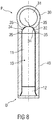
- Figure 8 is a sectional view of an embodiment of a drug delivery device 10 with the proximal gripping lug 30.
- the gripping lug 30 has an inner surface 32 forming a cavity 33 configured to be assembled onto the back end P of the housing 11 of the device 10.
- the cavity 33 comprises a form, shape and/or size corresponding to the form, shape and size of the respective back end P of the drug delivery device 10.
- the back end P of the device 10 has a convex form and the cavity 33 of the lug 30 has a concave form.
- the gripping lug 30 is hold on to the back end P of the housing 11 by at least one of a force-fit connection and form-fit connection.
- the gripping lug 30 comprises an inner retainer 34 configured to be fixed onto the back end P.
- the retainer 34 is formed on the inner surface 32 of the gripping lug 30.
- the retainer 34 comprises locking hooks 35 radially extending from the inner surface 32. The locking hooks 35 are bevelled and grab into the outer surface of the housing 11.
- Figures 9A to 9D are different perspective views showing a removing sequence of a long outer cap 40 from a drug delivery device 10.
- Figure 9A shows a delivery state of pack 50 in which the drug delivery device 10 is encapsulated by the outer cap 40 and the gripping lug 30.
- Figure 9B shows a pre-use state in which a user takes the pack 50 and optionally checks condition of drug and label and grips with his index finger of one hand into the eyelet 31 of the gripping lug 30 and with his outer hand the outer cap 40.
- Arrow F1 shows how the user can pull the outer cap 40 from the device 10 and the gripping lug 30.
- FIG. 9C shows the de-capped pack 50 with the inner drug delivery device 10 which is now ready to use.
- Figure 9D shows the device 10 in a used state or delivery state in which it is pressed against an injection site 90.
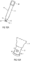
- Figures 10A, 10B are different perspective views of an alternative embodiment of a drug delivery device 10 with a different cap or needle sleeve design.
- the inner needle sleeve 13 of the device 10 comprises a marker 91 indicating the front end D or distal end of the device 10.
- the needle sleeve 13 comprises an opening 91.1, for instance a triangular opening.
- the triangular opening 91.1 points in the direction where the needle 17 projects from the needle sleeve 13.
- outer cap 40 may also comprise such a marker.
- Other forms, shapes or sizes of markers can be provided for indicating the front end D of the device 10 as well as of the pack 50.
- a drug or medicament can include at least one small or large molecule, or combinations thereof, in various types of formulations, for the treatment of one or more diseases.
- exemplary pharmaceutically active compounds may include small molecules; polypeptides, peptides and proteins (e.g., hormones, growth factors, antibodies, antibody fragments, and enzymes); carbohydrates and polysaccharides; and nucleic acids, double or single stranded DNA (including naked and cDNA), RNA, antisense nucleic acids such as antisense DNA and RNA, small interfering RNA (siRNA), ribozymes, genes, and oligonucleotides. Nucleic acids may be incorporated into molecular delivery systems such as vectors, plasmids, or liposomes. Mixtures of one or more of these drugs are also contemplated.
- a drug delivery device shall encompass any type of device or system configured to dispense a drug into a human or animal body.
- a drug delivery device may be an injection device (e.g., syringe, pen injector, auto injector, large-volume device, pump, perfusion system, or other device configured for intraocular, subcutaneous, intramuscular, or intravascular delivery), skin patch (e.g., osmotic, chemical, micro-needle), inhaler (e.g., nasal or pulmonary), implantable (e.g., coated stent, capsule), or feeding systems for the gastro-intestinal tract.
- the presently described drugs may be particularly useful with injection devices that include a needle, e.g., a small gauge needle.
- the drug or medicament may be contained in a primary package or "drug container" adapted for use with a drug delivery device.
- the drug container may be, e.g., a cartridge, syringe, reservoir, or other vessel configured to provide a suitable chamber for storage (e.g., short- or long-term storage) of one or more pharmaceutically active compounds.
- the chamber may be designed to store a drug for at least one day (e.g., 1 to at least 30 days).
- the chamber may be designed to store a drug for about 1 month to about 2 years. Storage may occur at room temperature (e.g., about 20°C), or refrigerated temperatures (e.g., from about - 4°C to about 4°C).
- the drug container may be or may include a dual-chamber cartridge configured to store two or more components of a drug formulation (e.g., a drug and a diluent, or two different types of drugs) separately, one in each chamber.
- the two chambers of the dual-chamber cartridge may be configured to allow mixing between the two or more components of the drug or medicament prior to and/or during dispensing into the human or animal body.
- the two chambers may be configured such that they are in fluid communication with each other (e.g., by way of a conduit between the two chambers) and allow mixing of the two components when desired by a user prior to dispensing.
- the two chambers may be configured to allow mixing as the components are being dispensed into the human or animal body.
- the drug delivery devices and drugs described herein can be used for the treatment and/or prophylaxis of many different types of disorders.
- exemplary disorders include, e.g., diabetes mellitus or complications associated with diabetes mellitus such as diabetic retinopathy, thromboembolism disorders such as deep vein or pulmonary thromboembolism.
- Further exemplary disorders are acute coronary syndrome (ACS), angina, myocardial infarction, cancer, macular degeneration, inflammation, hay fever, atherosclerosis and/or rheumatoid arthritis.
- ACS acute coronary syndrome
- angina myocardial infarction
- cancer macular degeneration
- inflammation hay fever
- atherosclerosis and/or rheumatoid arthritis.
- Exemplary drugs for the treatment and/or prophylaxis of diabetes mellitus or complications associated with diabetes mellitus include an insulin, e.g., human insulin, or a human insulin analogue or derivative, a glucagon-like peptide (GLP-1), GLP-1 analogues or GLP-1 receptor agonists, or an analogue or derivative thereof, a dipeptidyl peptidase-4 (DPP4) inhibitor, or a pharmaceutically acceptable salt or solvate thereof, or any mixture thereof.
- the term "derivative” refers to any substance which is sufficiently structurally similar to the original substance so as to have substantially similar functionality or activity (e.g., therapeutic effectiveness).
- Exemplary insulin analogues are Gly(A21), Arg(B31), Arg(B32) human insulin (insulin glargine); Lys(B3), Glu(B29) human insulin; Lys(B28), Pro(B29) human insulin; Asp(B28) human insulin; human insulin, wherein proline in position B28 is replaced by Asp, Lys, Leu, Val or Ala and wherein in position B29 Lys may be replaced by Pro; Ala(B26) human insulin; Des(B28-B30) human insulin; Des(B27) human insulin and Des(B30) human insulin.
- Exemplary insulin derivatives are, for example, B29-N-myristoyl-des(B30) human insulin; B29-N-palmitoyl-des(B30) human insulin; B29-N-myristoyl human insulin; B29-N-palmitoyl human insulin; B28-N-myristoyl LysB28ProB29 human insulin; B28-N-palmitoyl-LysB28ProB29 human insulin; B30-N-myristoyl-ThrB29LysB30 human insulin; B30-N-palmitoyl- ThrB29LysB30 human insulin; B29-N-(N-palmitoyl-gamma-glutamyl)-des(B30) human insulin; B29-N-(N-lithocholyl-gamma-glutamyl)-des(B30) human insulin; B29-N-( ⁇ -carboxyheptadecanoyl)-des(B30) human insulin and B29-N
- GLP-1, GLP-1 analogues and GLP-1 receptor agonists are, for example: Lixisenatide / AVE0010 / ZP10 / Lyxumia, Exenatide / Exendin-4 / Byetta / Bydureon / ITCA 650 / AC-2993 (a 39 amino acid peptide which is produced by the salivary glands of the Gila monster), Liraglutide / Victoza, Semaglutide, Taspoglutide, Syncria / Albiglutide, Dulaglutide, rExendin-4, CJC-1134-PC, PB-1023, TTP-054, Langlenatide / HM-11260C, CM-3, GLP-1 Eligen, ORMD-0901, NN-9924, NN-9926, NN-9927, Nodexen, Viador-GLP-1, CVX-096, ZYOG-1, ZYD-1, GSK-2374697, DA-3091, MAR-701
- An exemplary oligonucleotide is, for example: mipomersen / Kynamro, a cholesterol-reducing antisense therapeutic for the treatment of familial hypercholesterolemia.
- DPP4 inhibitors are Vildagliptin, Sitagliptin, Denagliptin, Saxagliptin, Berberine.
- hormones include hypophysis hormones or hypothalamus hormones or regulatory active peptides and their antagonists, such as Gonadotropine (Follitropin, Lutropin, Choriongonadotropin, Menotropin), Somatropine (Somatropin), Desmopressin, Terlipressin, Gonadorelin, Triptorelin, Leuprorelin, Buserelin, Nafarelin, and Goserelin.
- Gonadotropine Follitropin, Lutropin, Choriongonadotropin, Menotropin
- Somatropine Somatropin
- Desmopressin Terlipressin
- Gonadorelin Triptorelin
- Leuprorelin Buserelin
- Nafarelin Nafarelin
- Goserelin Goserelin.
- Exemplary polysaccharides include a glucosaminoglycane, a hyaluronic acid, a heparin, a low molecular weight heparin or an ultra-low molecular weight heparin or a derivative thereof, or a sulphated polysaccharide, e.g. a poly-sulphated form of the above-mentioned polysaccharides, and/or a pharmaceutically acceptable salt thereof.
- An example of a pharmaceutically acceptable salt of a poly-sulphated low molecular weight heparin is enoxaparin sodium.
- An example of a hyaluronic acid derivative is Hylan G-F 20 / Synvisc, a sodium hyaluronate.
- antibody refers to an immunoglobulin molecule or an antigen-binding portion thereof.
- antigen-binding portions of immunoglobulin molecules include F(ab) and F(ab') 2 fragments, which retain the ability to bind antigen.
- the antibody can be polyclonal, monoclonal, recombinant, chimeric, de-immunized or humanized, fully human, non-human, (e.g., murine), or single chain antibody.
- the antibody has effector function and can fix complement.
- the antibody has reduced or no ability to bind an Fc receptor.
- the antibody can be an isotype or subtype, an antibody fragment or mutant, which does not support binding to an Fc receptor, e.g., it has a mutagenized or deleted Fc receptor binding region.
- fragment refers to a polypeptide derived from an antibody polypeptide molecule (e.g., an antibody heavy and/or light chain polypeptide) that does not comprise a full-length antibody polypeptide, but that still comprises at least a portion of a full-length antibody polypeptide that is capable of binding to an antigen.
- Antibody fragments can comprise a cleaved portion of a full length antibody polypeptide, although the term is not limited to such cleaved fragments.
- Antibody fragments that are useful in the present disclosure include, for example, Fab fragments, F(ab')2 fragments, scFv (single-chain Fv) fragments, linear antibodies, monospecific or multispecific antibody fragments such as bispecific, trispecific, and multispecific antibodies (e.g., diabodies, triabodies, tetrabodies), minibodies, chelating recombinant antibodies, tribodies or bibodies, intrabodies, nanobodies, small modular immunopharmaceuticals (SMIP), binding-domain immunoglobulin fusion proteins, camelized antibodies, and VHH containing antibodies. Additional examples of antigen-binding antibody fragments are known in the art.
- CDR complementarity-determining region
- framework region refers to amino acid sequences within the variable region of both heavy and light chain polypeptides that are not CDR sequences, and are primarily responsible for maintaining correct positioning of the CDR sequences to permit antigen binding.
- framework regions themselves typically do not directly participate in antigen binding, as is known in the art, certain residues within the framework regions of certain antibodies can directly participate in antigen binding or can affect the ability of one or more amino acids in CDRs to interact with antigen.
- Exemplary antibodies are anti PCSK-9 mAb (e.g., Alirocumab), anti IL-6 mAb (e.g., Sarilumab), and anti IL-4 mAb (e.g., Dupilumab).
- anti PCSK-9 mAb e.g., Alirocumab
- anti IL-6 mAb e.g., Sarilumab
- anti IL-4 mAb e.g., Dupilumab
- the compounds described herein may be used in pharmaceutical formulations comprising (a) the compound(s) or pharmaceutically acceptable salts thereof, and (b) a pharmaceutically acceptable carrier.
- the compounds may also be used in pharmaceutical formulations that include one or more other active pharmaceutical ingredients or in pharmaceutical formulations in which the present compound or a pharmaceutically acceptable salt thereof is the only active ingredient.
- the pharmaceutical formulations of the present disclosure encompass any formulation made by admixing a compound described herein and a pharmaceutically acceptable carrier.
- Pharmaceutically acceptable salts of any drug described herein are also contemplated for use in drug delivery devices.
- Pharmaceutically acceptable salts are for example acid addition salts and basic salts.
- Acid addition salts are e.g. HCl or HBr salts.
- Basic salts are e.g. salts having a cation selected from an alkali or alkaline earth metal, e.g.
- R1 to R4 independently of each other mean: hydrogen, an optionally substituted C1-C6-alkyl group, an optionally substituted C2-C6-alkenyl group, an optionally substituted C6-C10-aryl group, or an optionally substituted C6-C10-heteroaryl group.
- R1 to R4 independently of each other mean: hydrogen, an optionally substituted C1-C6-alkyl group, an optionally substituted C2-C6-alkenyl group, an optionally substituted C6-C10-aryl group, or an optionally substituted C6-C10-heteroaryl group.
- solvates are for example hydrates or alkanolates such as methanolates or ethanolates.
Landscapes
- Health & Medical Sciences (AREA)
- Vascular Medicine (AREA)
- Engineering & Computer Science (AREA)
- Anesthesiology (AREA)
- Biomedical Technology (AREA)
- Heart & Thoracic Surgery (AREA)
- Hematology (AREA)
- Life Sciences & Earth Sciences (AREA)
- Animal Behavior & Ethology (AREA)
- General Health & Medical Sciences (AREA)
- Public Health (AREA)
- Veterinary Medicine (AREA)
- Diabetes (AREA)
- Infusion, Injection, And Reservoir Apparatuses (AREA)
Abstract
The invention relates to a drug delivery device (10) comprising at least a housing (11), a drug container (24) with a needle (17), and a cap (12.2, 40), wherein the housing (11) has an inner surface (32) forming a cavity (33) configured to retain the drug container (24) and the cap (12.2, 40) being configured to be releasably connected to the housing (11), and wherein a back end (P) of the device (10) opposite to a front end (D) of the device (10) directed to the cap (12.2, 40) comprises a gripping lug (30) axially protruding from the back end (P) of the device 10.
Description
- The disclosure generally relates to a drug delivery device. More particularly, the disclosure relates to an emergency pack for use with a drug delivery device.
- Conventionally, drug delivery devices comprise a housing or a shell in a shape of a pen which holds a drug cartridge or a drug container or a pre-filled syringe. Some drugs, e.g. emergency drugs like glucagon, are required in small quantities and have special requirements for a fast handling and assistance, in particular for a fast preparation, e.g. opening of the drug delivery device.
- Thus, there is a need for an improvement of handling the drug delivery device containing a specific drug, in particular an emergency drug.
- The present disclosure meets the foregoing need by providing a drug delivery device according to
claim 1. - Exemplary embodiments are provided in the dependent claims.
- In accordance with an aspect of the disclosure, a drug delivery device comprises at least a housing, a drug container with a needle and a cap, wherein the housing has an inner surface forming a cavity configured to retain the drug container, wherein the cap being configured to be releasably connected to the housing, in particular at a front end of the device, and wherein a back end of the device opposite to the front end directed to the cap comprises a gripping lug axially protruding from the back end of the device.
- In an assembled state of the drug delivery device, the housing and the cap are releasably interconnected with each other to encapsulate the drug container.
- The device is easy to handle. The gripping lug may comprise an eyelet or finger loop configured to be gripped by a finger of a user, in particular by index or middle finger. The gripping lug is configured such that a user easily knows how to pull out or open the drug delivery device. Further the gripping lug is configured such that, after a user removed the cap, he still holds the device in the hand. The gripping lug can potentially be used on all kind of drug delivery devices like pre-filled syringes, auto-injectors or pen-injectors.
- According to a further embodiment, the gripping lug has an inner surface forming a cavity configured to be assembled onto the back end of the housing. In particular, the cavity comprises a form, shape and/or size corresponding to the form, shape and size of the respective back end of the drug delivery device. For instance, the gripping lug is hold on to the back end of the housing by at least one of a force-fit connection and form-fit connection.
- According to another aspect, the gripping lug comprises a retainer configured to be fixed onto the back end of the device, e.g. the housing. In particular, the retainer is formed on the inner surface of the gripping lug. For forming a fixed connection, the retainer comprises at least one locking hook radially extending from the inner surface. In a possible embodiment, the retainer comprises a plurality of locking hooks all-round protruded and bevelled locking hooks which grab into the outer surface of the housing of the drug delivery device. Hence, the gripping lug may be attached onto different kind of drug delivery devices.
- In accordance with a further aspect, the cap has a length which corresponds with the length of the housing. In particular the cap has such a long length that it substantially full covers the drug delivery device, in particular the housing over its entire length including its distal or front end and the needle. Only a proximal end or the back end of the drug delivery device extends from the cap. This proximal end or back end of the drug delivery device is covered by the gripping lug.
- In a possible embodiment, the cap and the device, in particular the housing comprise corresponding crimp interfaces. Alternatively, the cap is releasably coupled to a device, in particular to its housing.
- Further, the needle sleeve may comprise a marker indicating the front end or distal end of the device. In particular, the needle sleeve may comprise an opening, for instance a triangular opening. The triangular opening points in the direction where the needle will project from the needle sleeve. The needle sleeve may comprise triangular openings on three sides of the sheath. Alternatively the needle sleeve may comprise two or four or more triangular openings.
- According to a further aspect, the cap comprises a shield grabber connecting the front cap to an outer surface of a needle shield, in particular a so-called rigid needle shield (RNS shield) covering the needle. The needle shield usually made from rubber which seals and covers the needle and the drug container from ambient. Such an integrated shield grabber inside the cap holds the rigid needle shield in an assembled state of the drug delivery device. Thus, removing of the cap will also remove the needle shield from the needle and make the drug delivery device ready to be used. This reduces handling steps for preparation of the drug delivery device.
- In particular, the shield grabber is provided with an inner hook element configured and arranged to hook on to an outer surface of the needle shield. In particular, the shield grabber and the needle shield comprise corresponding crimp features to fixedly hold the shield grabber and the needle shield together, in particular during removing of the cap as well as of the needle shield from the drug delivery device, in particular away from the needle.
- The disclosure provides a drug delivery device with a container or a syringe which is prefilled with a drug, in particular an emergency drug, e.g. an allergic drug or a diabetic drug, e.g. hypoglycemia. The drug delivery device is for instance an auto-injector, a pen-injector or a syringe.
- In a further embodiment, the drug delivery device comprises a piston which slides inside the container to inject the drug. Additionally, the drug delivery device comprises actuator means for automatically injecting a patient with said drug.
- The disclosure further provides an emergency pack comprising the above described drug delivery device.
- According to a further embodiment, an outer surface of the emergency pack, in particular of the housing or the outer cap, is configured in at least one parameter such that a specific drug contained within the drug delivery device may be quickly and easily identified by a person. In particular, the outer surface of the housing or the outer cap is coloured, e.g. is coloured in orange, red or yellow. Furthermore the outer surface may comprise a shape or form which allows a fast and easy identification of the specific drug contained within the drug delivery device. For instance, the outer surface may comprise a pen-shape.
- The drug delivery device, as described herein, may be configured to inject a medicament into a patient. For example, delivery could be sub-cutaneous, intra-muscular, or intravenous. Such a device could be operated by a patient or care-giver, such as a nurse or physician, and can include various types of safety syringe, pen-injector, or auto-injector. The device can include a cartridge-based system that requires piercing a sealed ampule before use. Volumes of medicament delivered with these various devices can range from about 0.5 ml to about 2 ml. Yet another device can include a large volume device ("LVD") or patch pump, configured to adhere to a patient's skin for a period of time (e.g., about 5, 15, 30, 60, or 120 minutes) to deliver a "large" volume of medicament (typically about 2 ml to about 5 ml).
In combination with a specific medicament, the presently described devices may also be customized in order to operate within required specifications. For example, the device may be customized to inject a medicament within a certain time period (e.g., about 3 to about 20 seconds for auto-injectors, and about 10 minutes to about 60 minutes for an LVD). Other specifications can include a low or minimal level of discomfort, or to certain conditions related to human factors, shelf-life, expiry, biocompatibility, environmental considerations, etc. Such variations can arise due to various factors, such as, for example, a drug ranging in viscosity from about 3 cP to about 50 cP. Consequently, a drug delivery device will often include a hollow needle ranging from about 25 to about 31 Gauge in size. Common sizes are 27 and 29 Gauge. - The delivery devices described herein can also include one or more automated functions. For example, one or more of needle insertion, medicament injection, and needle retraction can be automated. Energy for one or more automation steps can be provided by one or more energy sources. Energy sources can include, for example, mechanical, pneumatic, chemical, or electrical energy. For example, mechanical energy sources can include springs, levers, elastomers, or other mechanical mechanisms to store or release energy. One or more energy sources can be combined into a single device. Devices can further include gears, valves, or other mechanisms to convert energy into movement of one or more components of a device.
- The one or more automated functions of an auto-injector may be activated via an activation mechanism. Such an activation mechanism can include one or more of a button, a lever, a needle sleeve, or other activation component. Activation may be a one-step or multi-step process. That is, a user may need to activate one or more activation mechanism in order to cause the automated function. For example, a user may depress a needle sleeve against their body in order to cause injection of a medicament. In other devices, a user may be required to depress a button and retract a needle shield in order to cause injection.
- In addition, such activation may activate one or more mechanisms. For example, an activation sequence may activate at least two of needle insertion, medicament injection, and needle retraction. Some devices may also require a specific sequence of steps to cause the one or more automated functions to occur. Other devices may operate with sequence independent steps.
- Some delivery devices can include one or more functions of a safety syringe, pen-injector, or auto-injector. For example, a delivery device could include a mechanical energy source configured to automatically inject a medicament (as typically found in an auto-injector) and a dose setting mechanism (as typically found in a pen-injector).
- Further scope of applicability of the present disclosure will become apparent from the detailed description given hereinafter. However, it should be understood that the detailed description and specific examples, while indicating exemplary embodiments of the disclosure, are given by way of illustration only, since various changes and modifications within the spirit and scope of the disclosure will become apparent to those skilled in the art from this detailed description.
- The present disclosure will become more fully understood from the detailed description given below and the accompanying drawings, which are given by way of illustration only, and do not limit the present disclosure, and wherein:
- Figures 1A to 1C
- are schematic views of well-known drug delivery devices according to the prior art,
- Figure 2
- is a schematic perspective view of an embodiment of a drug delivery device with a gripping lug,
- Figure 3
- is an exploded view of a drug delivery device during removing of a cap,
- Figure 4
- is a schematic perspective view of a further embodiment of a drug delivery device with a gripping lug,
- Figure 5
- is an enlarged or sectional view of a drug delivery device with partially removed cap,
- Figure 6A, 6B
- is a schematic view of an alternative embodiment for a cap of the drug delivery device, and
- Figure 7
- is an enlarged sectional view of a distal portion of a drug delivery device with an alternative cap assembly,
- Figure 8
- is a sectional view of an embodiment of a drug delivery device,
- Figures 9A to 9D
- are different perspective views showing a removing sequence of a cap from a drug delivery device, and
- Figures 10A, 10B
- are different perspective views of an alternative embodiment of a drug delivery device with a different cap design.
- Corresponding parts are marked with the same reference symbols in all figures.
- According to some embodiments of the present disclosure, an exemplary
drug delivery device 10 is shown inFigures 1A and1 B. -
Device 10, as described above, is configured to inject a medicament into a patient's body. -
Device 10 includes ahousing 11 which typically contains a reservoir containing the medicament to be injected (e.g., a syringe or a container) and the components required to facilitate one or more steps of the delivery process. -
Device 10 can also include acap assembly 12 that can be detachably mounted to thehousing 11, in particular on a distal or front end D of thedevice 10. Typically, a user must remove cap assembly or cap 12 fromhousing 11 beforedevice 10 can be operated. - As shown,
housing 11 is substantially cylindrical and has a substantially constant diameter along the longitudinal axis X. Thehousing 11 has adistal region 20 and aproximal region 21. The term "distal" refers to a location that is relatively closer to a site of injection, and the term "proximal" refers to a location that is relatively further away from the injection site. -
Device 10 can also include aneedle sleeve 13 coupled to thehousing 11 to permit movement of thesleeve 13 relative to thehousing 11. For example, thesleeve 13 can move in a longitudinal direction parallel to longitudinal axis X. Specifically, movement of thesleeve 13 in a proximal direction can permit aneedle 17 to extend fromdistal region 20 ofhousing 11. Insertion of theneedle 17 can occur via several mechanisms. For example, theneedle 17 may be fixedly located relative tohousing 11 and initially be located within anextended needle sleeve 13. Proximal movement of thesleeve 13 by placing a distal end ofsleeve 13 against a patient's body and movinghousing 11 in a distal direction will uncover the distal end ofneedle 17. Such relative movement allows the distal end ofneedle 17 to extend into the patient's body. Such insertion is termed "manual" insertion as theneedle 17 is manually inserted via the patient's manual movement of thehousing 11 relative to thesleeve 13. - Another form of insertion is "automated," whereby the
needle 17 moves relative tohousing 11. Such insertion can be triggered by movement ofsleeve 13 or by another form of activation, such as, for example, abutton 22. As shown inFigures 1A & 1B ,button 22 is located at a proximal or back end P of thehousing 11. However, in other embodiments,button 22 could be located on a side ofhousing 11. In further embodiments, thebutton 22 has been deleted and is replaced for instance by a sleeve trigger mechanism, e.g. provided by pushing theneedle sleeve 13 inside the housing when the drug delivery device is put onto an injection side. - Other manual or automated features can include drug injection or needle retraction, or both. Injection is the process by which a bung or
piston 23 is moved from a proximal location within a container orsyringe 24 to a more distal location within thesyringe 24 in order to force a medicament from thesyringe 24 throughneedle 17. - In some embodiments, a drive spring (not shown) is under compression before
device 10 is activated. A proximal end of the drive spring can be fixed withinproximal region 21 ofhousing 11, and a distal end of the drive spring can be configured to apply a compressive force to a proximal surface ofpiston 23. Following activation, at least part of the energy stored in the drive spring can be applied to the proximal surface ofpiston 23. This compressive force can act onpiston 23 to move it in a distal direction. Such distal movement acts to compress the liquid medicament within thesyringe 24, forcing it out ofneedle 17. - Following injection, the
needle 17 can be retracted withinsleeve 13 orhousing 11. Retraction can occur whensleeve 13 moves distally as a user removesdevice 10 from a patient's body. This can occur asneedle 17 remains fixedly located relative tohousing 11. Once a distal end of thesleeve 13 has moved past a distal end of theneedle 17, and theneedle 17 is covered, thesleeve 13 can be locked. Such locking can include locking any proximal movement of thesleeve 13 relative to thehousing 11. - Another form of needle retraction can occur if the
needle 17 is moved relative to thehousing 11. Such movement can occur if the syringe within thehousing 11 is moved in a proximal direction relative to thehousing 11. This proximal movement can be achieved by using a retraction spring (not shown), located in thedistal region 20. A compressed retraction spring, when activated, can supply sufficient force to thesyringe 24 to move it in a proximal direction. Following sufficient retraction, any relative movement between theneedle 17 and thehousing 11 can be locked with a locking mechanism. In addition,button 22 or other components ofdevice 10 can be locked as required. - In some embodiments, the housing may comprise a
window 11a through which thesyringe 24 can be monitored. -
Figure 1C shows a schematic view of another well-knowndrug delivery device 10. Thedrug delivery device 10 comprises acap 12 attached to thehousing 11 on a distal end or front end D of thedevice 10. A back end P of thedevice 10, in particular of thehousing 11 has a curved or dome shape. - The
cap 12 has an enlarged distal end. In particular, thecap 12 is substantially cylindrical and has a substantially constant diameter along the longitudinal axis X. At a distal end the diameter of thecap 12 increases and forms an enlarged front end D of thedevice 10. -
Figure 2 is a schematic perspective view of an embodiment of adrug delivery device 10 with an integratedgripping lug 30 at aproximal region 21 of thedrug delivery device 10. - The
drug delivery device 10 is provided with acontainer 24 which is prefilled with a drug, in particular an emergency drug, e.g. an allergic drug or a diabetic drug, e.g. hypoglycemia or epinephrine. Thedrug delivery device 10 is for instance an auto-injector, a pen-injector or a syringe. Thedrug delivery device 10 is finally assembled and a final device which is ready to use. - As shown, the
device 10 comprises ahousing 11 which is substantially cylindrical and has a substantially constant diameter along the longitudinal axis X. Further, thehousing 11 comprises a round cross section. Alternatively, thehousing 11 may comprise a rectangular, circular or oval cross section. - The
drug delivery device 10 with thegripping lug 30 and thecap assembly 12 serves as an emergency medical kit orpack 50. Thehousing 11 is for instance coloured and labelled according to the emergency medical product. In particular, thehousing 11 comprises at least an identification portion, e.g. a window, recess, marking or opening. This allows the user to immediately intuitively assess and locate thedrug delivery device 10 with the specific emergency medical product without searching devices and medications. The disclosure allows using known and usualdrug delivery devices 10, in particular auto-injectors in various styles, for emergency drugs. Thehousing 11 is configured as strong lightweight outer housing or encapsulation device. In particular, thehousing 11 is formed as an outer shell which is closed by thecap assembly 12. - The
cap assembly 12 and thegripping lug 30 are tightly closed in an assembled state. In particular, the assembledemergency pack 50 is hermetically sealed or tightly closed. - The
gripping lug 30 is configured as one of the easiest mouldable one-part solutions. Thegripping lug 30 serves as a de-capping aid, described below in more detail. - The
drug delivery device 10, in particular thehousing 11 is closed at itsdistal region 20 by thecap assembly 12 which is formed as a short sleeve. Thecap assembly 12 comprises an inner needle shield 12.1 and an outer cap 12.2. - The cap 12.2 comprises a
shield grabber 75 connecting to an outer surface of the needle shield 12.1 which covers theneedle 17. Theshield grabber 75 is provided with inner hook element 75.1 configured and arranged to hook on to the outer surface of the needle shield 12.1. - The outer cap 12.2 is substantially cylindrical and has a substantially constant diameter along the longitudinal axis X. In the distal direction the diameter of the cap 12.2 increases and forms an enlarged
distal portion 52 of thepack 50. The cap 12.2 is releasably coupled to thehousing 11 at thedistal region 20 of thedevice 10. - A user must remove the cap 12.2 from the
housing 11 before thedrug delivery device 10 can be operated and used. - The cap 12.2 is for example configured to remove the needle shield 12.1, e.g. a rigid needle shield (RNS shield), from the
drug delivery device 10, too. In particular, the cap 12.2 and the needle shield 12.1 are fixedly coupled to each other. Due to coupling of the cap 12.2 with the inner needle shield 12.1, the needle shield 12.1 is simultaneously removable from thedrug delivery device 10 while the cap 12.2 is removed from thedevice 10. After removing of the cap 12.2 together with the needle shield 12.1, theneedle 17 of thedrug delivery device 10 is further covered by thesleeve 13. - The cap 12.2 and the inner needle shield 12.1 may comprise corresponding crimp interfaces 70. In particular the crimp interfaces 70 may be formed as a corresponding crimp parts, e.g. a metal crimp and a nut, in particular as a slitted metal crimp engaging a nut. Crimp interfaces 70 allow a holding and fixation of the cap 12.2 together with the inner needle shield 12.1 by its crimp or clamp forces.
- Allowing an intuitive gripping and an easy handling of the
device 10, in particular in emergency cases, thegripping lug 30 may comprise aneyelet 31 or a finger loop. Theeyelet 31 is formed for example as a gripping ring or finger loop extending from aproximal portion 51 of thepack 50. Thegripping lug 30 is configured so that it could be intuitively gripped by an index finger or a middle finger as it is shown infigure 3 . - The
gripping lug 30 allows an intuitive gripping and, thus, a fast decoupling of the cap 12.2 from thedevice 10 and, thus, an easy and fast opening of theemergency pack 50 to use thedrug delivery device 10 e.g. in an emergency case. - However, in further embodiments, the
gripping lug 30 may additionally be configured with a gripping material on the outer surface of thelug 30 and/or as a structured, e.g. profiled outer surface of thelug 30. -
Figure 4 is a schematic perspective view of another embodiment of adrug delivery device 10 with agripping lug 30 and a largeouter cap 40. - In particular,
figure 4 shows an embodiment of anemergency pack 50 comprising adrug delivery device 10 encapsulated by agripping lug 30 and anouter cap 40. Theouter cap 40 and thegripping lug 30 are configured to form an encapsulation of thedrug delivery device 10, in particular in the form of theemergency pack 50. - The
drug delivery device 10 is also provided with acontainer 24 which is prefilled with a drug, in particular an emergency drug, e.g. an allergic drug or a diabetic drug, e.g. Hypoglycemia, as described above. - The
drug delivery device 10 is for instance an auto-injector, a pen-injector or a syringe. Thedrug delivery device 10 is finally assembled and a final device which is ready to use. - As shown, the
emergency pack 50 is substantially cylindrical and has a substantially constant diameter along the longitudinal axis X. Further, theemergency pack 50 comprises a round cross section. Alternatively, theemergency pack 50 may comprise a rectangular, circular or oval cross section. Theemergency pack 50 has aproximal portion 51 and adistal portion 52. - The
emergency pack 50 serves as an emergency medical kit comprising thedrug delivery device 10, with e.g. a prefilled syringe orcontainer 24 in various styles with an emergency medical product or drug, e.g. epinephrine. - The
emergency pack 50 is for instance coloured and labelled according to the emergency medical product. In particular, theemergency pack 50 comprises at least an identification portion, e.g. awindow 11 a, recess, marking or opening. This allows the user to immediately intuitively assess and locate thedrug delivery device 10 with the specific emergency medical product without searching devices and medications. The disclosure allows using known and usualdrug delivery devices 10, in particular auto-injectors in various styles, for emergency drugs. - The
emergency pack 50 is configured as strong lightweight outer housing or encapsulation device. In particular, theouter cap 40 is formed as an outer shell which is closed by thegripping lug 30. The outer shell can individually change and is adapted to accommodate thedrug delivery device 10 so that no parts of thedrug delivery device 10 extend through theemergency pack 50. - The
outer cap 40 and thegripping lug 30 are tightly closed in an assembled state. In particular, the assembledemergency pack 50 hermetically seals or tightly closes thedrug delivery device 10. Further theemergency pack 50 is reinforced by e.g. reinforcement elements like inner ribs or reinforcement material like reinforced plastic, e.g. fiber-reinforced plastic. Theemergency pack 50 is impact-resistant and heat resistant. Hence, thedrug delivery device 10 encapsulated by theemergency pack 50 is protected against impacts, heat and/or fluids. - Each component or part, e.g. the
outer cap 40 and thegripping lug 30 are conceivable depending on the usability needs. Thegripping lug 30 as well as theouter cap 40 is configured as one of the easiest mouldable one-part solutions. - Additionally, a
seal element 60, e.g. an O-ring seal or a flexible seal, may be arranged between theouter cap 40 and thegripping lug 30. - The
emergency pack 50 is designed to contain at least adrug delivery device 10, e.g. an auto-injector containing a pre-filled syringe orcontainer 24, the outer cap 40 (e.g. a shell) and the gripping lug 30 (e.g. as de-capping aid), described below in more detail. - The
drug delivery device 10 is encapsulated by theouter cap 40 which is formed as a long sleeve. Theouter cap 40 is substantially cylindrical and has a substantially constant diameter along the longitudinal axis X. Theouter cap 40 is releasably coupled to thegripping lug 30 at the back end P of thepack 50 and/or to thehousing 11 at itsproximal region 21. A user must remove theouter cap 40 from thedevice 10, in particular from thegripping lug 30 and/or thehousing 11 before thedrug delivery device 10 can be operated. - The
outer cap 40 is for example configured to remove thecap assembly 12, e.g. a rigid needle shield 12.1 (RNS shield) in combination with a cap 12.2 of thedrug delivery device 10, too. After removing of theouter cap 40 together with thecap assembly 12 and thus with the cap 12.2 and the rigid needle shield 12.1 from thedrug delivery device 10, theneedle 17 of thedrug delivery device 10 is further covered by thesleeve 13. - De-capping of the
emergency pack 50 can occur via several mechanisms. For example, theouter cap 40 may be removed alone from thedrug delivery device 10 and thecap assembly 12 may be subsequently removed from thedrug delivery device 10. According to another example, due to coupling of theouter cap 40 with theinner cap assembly 12, thecap assembly 12 is simultaneously removable from thedrug delivery device 10 while theouter cap 40 is removed from thedevice 10. - The
outer cap 40 and theinner cap assembly 12 may comprise corresponding crimp interfaces 70. In particular the crimp interfaces 70 may be formed as corresponding crimp parts, e.g. a metal crimp and a nut, in particular as a slitted metal crimp engaging a nut. Crimp interfaces 70 allow a holding and fixation of theouter cap 40 together with theinner cap assembly 12 by its crimp or clamp forces. - In particular, the crimp interfaces 70 comprise pins or hooks 71 which snap-in into pockets 72 (or windows, recesses, opening) of the
cap assembly 12 of thedrug delivery device 10. Thehooks 71 or pins eliminate free play tolerances between plastic components of thedrug delivery device 10 and theemergency pack 50. - Allowing an intuitive gripping and an easy handling of the
device 10, in particular in emergency cases, thegripping lug 30 may comprise theeyelet 31 or a finger loop. Theeyelet 31 is formed for example as a gripping ring or finger loop extending from theproximal portion 51 of thepack 50. However, in further embodiments, thegripping lug 30 may additionally be configured as a gripping material on the outer surface of thelug 30 and/or as a structured, e.g. profiled outer surface of thelug 30. - The
gripping lug 30 allows an easy and fast decoupling of the longouter cap 40 from thedevice 10 at theproximal portion 51 of thepack 50, in particular in the region ofseal element 60. While removing the longouter cap 40 from thedrug delivery device 10, in particular from thegripping lug 30 theseal element 60 breaks, as it is shown infigure 5 . -
Figures 6A ,6B show schematic views of an alternative embodiment for a longouter cap 40 for removing aninner cap assembly 12 from thedrug delivery device 10. The longouter cap 40 is coupled to theinner cap assembly 12 of thedrug delivery device 10. - The
outer cap 40 may comprise anend stop 80 at its inner distal end. Theend stop 80 serves as an interface to thedistal region 20 or front end D of thedrug delivery device 10, in particular to the distal end of thecap assembly 12 during handling and assembly. -
Figure 6A shows theemergency pack 50 in an assembled state with thecap assembly 12 attached to thedrug delivery device 10.Figure 6B shows theemergency pack 50 in a state in which theouter cap 40 together with thecap assembly 12 is partially removed from thedrug delivery device 10. Theneedle 17 is still covered by theneedle sleeve 13. - The
crimp interface 70 is configured to fixedly hold theouter cap 40 onto thecap assembly 12. In particular, thecrimp interface 70 comprises one ormore locking arms 71 axially extending from the distal end of theouter cap 40 inwards. - For instance, the
arms 71 comprisefastener 72, e.g. locking hook or snap interface which locks onto the enlarged distal portion of thecap assembly 12 or into a pocket or opening (not shown) of thecap assembly 12. Thefasteners 72 are configured to be locked in a friction-fit or force-fit manner. -
Figure 7 shows is an enlarged sectional view of thedistal portion 52 of thepack 50 with an alternativeintegrated crimp interface 70 of theouter cap 40 with theinner cap assembly 12 of thedrug delivery device 10. Thecrimp interface 70 of theouter cap 40 and thus theouter cap 40 are formed as one piece with theinner cap assembly 12. For instance, theouter cap 40 and theinner cap assembly 12 are formed as one-piece part, e.g. as an injection-moulded part. -
Figure 8 is a sectional view of an embodiment of adrug delivery device 10 with the proximalgripping lug 30. Thegripping lug 30 has aninner surface 32 forming a cavity 33 configured to be assembled onto the back end P of thehousing 11 of thedevice 10. - The cavity 33 comprises a form, shape and/or size corresponding to the form, shape and size of the respective back end P of the
drug delivery device 10. For instance, the back end P of thedevice 10 has a convex form and the cavity 33 of thelug 30 has a concave form. - Further, the
gripping lug 30 is hold on to the back end P of thehousing 11 by at least one of a force-fit connection and form-fit connection. For instance, thegripping lug 30 comprises aninner retainer 34 configured to be fixed onto the back end P. Theretainer 34 is formed on theinner surface 32 of thegripping lug 30. For forming a fixed connection, theretainer 34 comprises locking hooks 35 radially extending from theinner surface 32. The locking hooks 35 are bevelled and grab into the outer surface of thehousing 11. -
Figures 9A to 9D are different perspective views showing a removing sequence of a longouter cap 40 from adrug delivery device 10. -
Figure 9A shows a delivery state ofpack 50 in which thedrug delivery device 10 is encapsulated by theouter cap 40 and thegripping lug 30. -
Figure 9B shows a pre-use state in which a user takes thepack 50 and optionally checks condition of drug and label and grips with his index finger of one hand into theeyelet 31 of thegripping lug 30 and with his outer hand theouter cap 40. Arrow F1 shows how the user can pull theouter cap 40 from thedevice 10 and thegripping lug 30. -
Figure 9C shows thede-capped pack 50 with the innerdrug delivery device 10 which is now ready to use. -
Figure 9D shows thedevice 10 in a used state or delivery state in which it is pressed against aninjection site 90. -
Figures 10A, 10B are different perspective views of an alternative embodiment of adrug delivery device 10 with a different cap or needle sleeve design. In particular, theinner needle sleeve 13 of thedevice 10 comprises amarker 91 indicating the front end D or distal end of thedevice 10. Theneedle sleeve 13 comprises an opening 91.1, for instance a triangular opening. The triangular opening 91.1 points in the direction where theneedle 17 projects from theneedle sleeve 13. - Additionally, the
outer cap 40 may also comprise such a marker. Other forms, shapes or sizes of markers can be provided for indicating the front end D of thedevice 10 as well as of thepack 50. - The terms "drug" or "medicament" are used herein to describe one or more pharmaceutically active compounds. As described below, a drug or medicament can include at least one small or large molecule, or combinations thereof, in various types of formulations, for the treatment of one or more diseases. Exemplary pharmaceutically active compounds may include small molecules; polypeptides, peptides and proteins (e.g., hormones, growth factors, antibodies, antibody fragments, and enzymes); carbohydrates and polysaccharides; and nucleic acids, double or single stranded DNA (including naked and cDNA), RNA, antisense nucleic acids such as antisense DNA and RNA, small interfering RNA (siRNA), ribozymes, genes, and oligonucleotides. Nucleic acids may be incorporated into molecular delivery systems such as vectors, plasmids, or liposomes. Mixtures of one or more of these drugs are also contemplated.
- The term "drug delivery device" shall encompass any type of device or system configured to dispense a drug into a human or animal body. Without limitation, a drug delivery device may be an injection device (e.g., syringe, pen injector, auto injector, large-volume device, pump, perfusion system, or other device configured for intraocular, subcutaneous, intramuscular, or intravascular delivery), skin patch (e.g., osmotic, chemical, micro-needle), inhaler (e.g., nasal or pulmonary), implantable (e.g., coated stent, capsule), or feeding systems for the gastro-intestinal tract. The presently described drugs may be particularly useful with injection devices that include a needle, e.g., a small gauge needle.
- The drug or medicament may be contained in a primary package or "drug container" adapted for use with a drug delivery device. The drug container may be, e.g., a cartridge, syringe, reservoir, or other vessel configured to provide a suitable chamber for storage (e.g., short- or long-term storage) of one or more pharmaceutically active compounds. For example, in some instances, the chamber may be designed to store a drug for at least one day (e.g., 1 to at least 30 days). In some instances, the chamber may be designed to store a drug for about 1 month to about 2 years. Storage may occur at room temperature (e.g., about 20°C), or refrigerated temperatures (e.g., from about - 4°C to about 4°C). In some instances, the drug container may be or may include a dual-chamber cartridge configured to store two or more components of a drug formulation (e.g., a drug and a diluent, or two different types of drugs) separately, one in each chamber. In such instances, the two chambers of the dual-chamber cartridge may be configured to allow mixing between the two or more components of the drug or medicament prior to and/or during dispensing into the human or animal body. For example, the two chambers may be configured such that they are in fluid communication with each other (e.g., by way of a conduit between the two chambers) and allow mixing of the two components when desired by a user prior to dispensing. Alternatively or in addition, the two chambers may be configured to allow mixing as the components are being dispensed into the human or animal body.
- The drug delivery devices and drugs described herein can be used for the treatment and/or prophylaxis of many different types of disorders. Exemplary disorders include, e.g., diabetes mellitus or complications associated with diabetes mellitus such as diabetic retinopathy, thromboembolism disorders such as deep vein or pulmonary thromboembolism. Further exemplary disorders are acute coronary syndrome (ACS), angina, myocardial infarction, cancer, macular degeneration, inflammation, hay fever, atherosclerosis and/or rheumatoid arthritis.
- Exemplary drugs for the treatment and/or prophylaxis of diabetes mellitus or complications associated with diabetes mellitus include an insulin, e.g., human insulin, or a human insulin analogue or derivative, a glucagon-like peptide (GLP-1), GLP-1 analogues or GLP-1 receptor agonists, or an analogue or derivative thereof, a dipeptidyl peptidase-4 (DPP4) inhibitor, or a pharmaceutically acceptable salt or solvate thereof, or any mixture thereof. As used herein, the term "derivative" refers to any substance which is sufficiently structurally similar to the original substance so as to have substantially similar functionality or activity (e.g., therapeutic effectiveness).
- Exemplary insulin analogues are Gly(A21), Arg(B31), Arg(B32) human insulin (insulin glargine); Lys(B3), Glu(B29) human insulin; Lys(B28), Pro(B29) human insulin; Asp(B28) human insulin; human insulin, wherein proline in position B28 is replaced by Asp, Lys, Leu, Val or Ala and wherein in position B29 Lys may be replaced by Pro; Ala(B26) human insulin; Des(B28-B30) human insulin; Des(B27) human insulin and Des(B30) human insulin.
- Exemplary insulin derivatives are, for example, B29-N-myristoyl-des(B30) human insulin; B29-N-palmitoyl-des(B30) human insulin; B29-N-myristoyl human insulin; B29-N-palmitoyl human insulin; B28-N-myristoyl LysB28ProB29 human insulin; B28-N-palmitoyl-LysB28ProB29 human insulin; B30-N-myristoyl-ThrB29LysB30 human insulin; B30-N-palmitoyl- ThrB29LysB30 human insulin; B29-N-(N-palmitoyl-gamma-glutamyl)-des(B30) human insulin; B29-N-(N-lithocholyl-gamma-glutamyl)-des(B30) human insulin; B29-N-(ω-carboxyheptadecanoyl)-des(B30) human insulin and B29-N-(ω-carboxyheptadecanoyl) human insulin. Exemplary GLP-1, GLP-1 analogues and GLP-1 receptor agonists are, for example: Lixisenatide / AVE0010 / ZP10 / Lyxumia, Exenatide / Exendin-4 / Byetta / Bydureon / ITCA 650 / AC-2993 (a 39 amino acid peptide which is produced by the salivary glands of the Gila monster), Liraglutide / Victoza, Semaglutide, Taspoglutide, Syncria / Albiglutide, Dulaglutide, rExendin-4, CJC-1134-PC, PB-1023, TTP-054, Langlenatide / HM-11260C, CM-3, GLP-1 Eligen, ORMD-0901, NN-9924, NN-9926, NN-9927, Nodexen, Viador-GLP-1, CVX-096, ZYOG-1, ZYD-1, GSK-2374697, DA-3091, MAR-701, MAR709, ZP-2929, ZP-3022, TT-401, BHM-034. MOD-6030, CAM-2036, DA-15864, ARI-2651, ARI-2255, Exenatide-XTEN and Glucagon-Xten.
- An exemplary oligonucleotide is, for example: mipomersen / Kynamro, a cholesterol-reducing antisense therapeutic for the treatment of familial hypercholesterolemia.
- Exemplary DPP4 inhibitors are Vildagliptin, Sitagliptin, Denagliptin, Saxagliptin, Berberine.
- Exemplary hormones include hypophysis hormones or hypothalamus hormones or regulatory active peptides and their antagonists, such as Gonadotropine (Follitropin, Lutropin, Choriongonadotropin, Menotropin), Somatropine (Somatropin), Desmopressin, Terlipressin, Gonadorelin, Triptorelin, Leuprorelin, Buserelin, Nafarelin, and Goserelin.
- Exemplary polysaccharides include a glucosaminoglycane, a hyaluronic acid, a heparin, a low molecular weight heparin or an ultra-low molecular weight heparin or a derivative thereof, or a sulphated polysaccharide, e.g. a poly-sulphated form of the above-mentioned polysaccharides, and/or a pharmaceutically acceptable salt thereof. An example of a pharmaceutically acceptable salt of a poly-sulphated low molecular weight heparin is enoxaparin sodium. An example of a hyaluronic acid derivative is
Hylan G-F 20 / Synvisc, a sodium hyaluronate. - The term "antibody", as used herein, refers to an immunoglobulin molecule or an antigen-binding portion thereof. Examples of antigen-binding portions of immunoglobulin molecules include F(ab) and F(ab')2 fragments, which retain the ability to bind antigen. The antibody can be polyclonal, monoclonal, recombinant, chimeric, de-immunized or humanized, fully human, non-human, (e.g., murine), or single chain antibody. In some embodiments, the antibody has effector function and can fix complement. In some embodiments, the antibody has reduced or no ability to bind an Fc receptor. For example, the antibody can be an isotype or subtype, an antibody fragment or mutant, which does not support binding to an Fc receptor, e.g., it has a mutagenized or deleted Fc receptor binding region.
- The terms "fragment" or "antibody fragment" refer to a polypeptide derived from an antibody polypeptide molecule (e.g., an antibody heavy and/or light chain polypeptide) that does not comprise a full-length antibody polypeptide, but that still comprises at least a portion of a full-length antibody polypeptide that is capable of binding to an antigen. Antibody fragments can comprise a cleaved portion of a full length antibody polypeptide, although the term is not limited to such cleaved fragments. Antibody fragments that are useful in the present disclosure include, for example, Fab fragments, F(ab')2 fragments, scFv (single-chain Fv) fragments, linear antibodies, monospecific or multispecific antibody fragments such as bispecific, trispecific, and multispecific antibodies (e.g., diabodies, triabodies, tetrabodies), minibodies, chelating recombinant antibodies, tribodies or bibodies, intrabodies, nanobodies, small modular immunopharmaceuticals (SMIP), binding-domain immunoglobulin fusion proteins, camelized antibodies, and VHH containing antibodies. Additional examples of antigen-binding antibody fragments are known in the art.
- The terms "Complementarity-determining region" or "CDR" refer to short polypeptide sequences within the variable region of both heavy and light chain polypeptides that are primarily responsible for mediating specific antigen recognition. The term "framework region" refers to amino acid sequences within the variable region of both heavy and light chain polypeptides that are not CDR sequences, and are primarily responsible for maintaining correct positioning of the CDR sequences to permit antigen binding. Although the framework regions themselves typically do not directly participate in antigen binding, as is known in the art, certain residues within the framework regions of certain antibodies can directly participate in antigen binding or can affect the ability of one or more amino acids in CDRs to interact with antigen.
- Exemplary antibodies are anti PCSK-9 mAb (e.g., Alirocumab), anti IL-6 mAb (e.g., Sarilumab), and anti IL-4 mAb (e.g., Dupilumab).
- The compounds described herein may be used in pharmaceutical formulations comprising (a) the compound(s) or pharmaceutically acceptable salts thereof, and (b) a pharmaceutically acceptable carrier. The compounds may also be used in pharmaceutical formulations that include one or more other active pharmaceutical ingredients or in pharmaceutical formulations in which the present compound or a pharmaceutically acceptable salt thereof is the only active ingredient. Accordingly, the pharmaceutical formulations of the present disclosure encompass any formulation made by admixing a compound described herein and a pharmaceutically acceptable carrier.
- Pharmaceutically acceptable salts of any drug described herein are also contemplated for use in drug delivery devices. Pharmaceutically acceptable salts are for example acid addition salts and basic salts. Acid addition salts are e.g. HCl or HBr salts. Basic salts are e.g. salts having a cation selected from an alkali or alkaline earth metal, e.g. Na+, or K+, or Ca2+, or an ammonium ion N+(R1)(R2)(R3)(R4), wherein R1 to R4 independently of each other mean: hydrogen, an optionally substituted C1-C6-alkyl group, an optionally substituted C2-C6-alkenyl group, an optionally substituted C6-C10-aryl group, or an optionally substituted C6-C10-heteroaryl group. Further examples of pharmaceutically acceptable salts are known to those of skill in the arts.
- Pharmaceutically acceptable solvates are for example hydrates or alkanolates such as methanolates or ethanolates.
- Those of skill in the art will understand that modifications (additions and/or removals) of various components of the substances, formulations, apparatuses, methods, systems and embodiments described herein may be made without departing from the full scope and spirit of the present disclosure, which encompass such modifications and any and all equivalents thereof.
-
- 10
- drug delivery device
- 11
- housing
- 11a
- window
- 12
- cap assembly
- 12.1
- needle shield
- 12.2
- cap
- 13
- needle sleeve
- 17
- needle
- 20
- distal region of the drug delivery device
- 21
- proximal region of the drug delivery device
- 22
- button
- 23
- piston
- 24
- syringe or container
- 30
- gripping lug
- 31
- eyelet
- 32
- inner surface
- 33
- cavity
- 34
- retainer
- 35
- locking hooks
- 40
- outer cap
- 50
- emergency pack
- 51
- proximal portion
- 52
- distal portion
- 60
- seal
- 70
- crimp interface
- 71
- arm
- 72
- fastener
- 75
- shield grabber
- 75.1
- hook
- 80
- end stop
- 90
- injection site
- 91
- marker
- 91.1
- opening
Claims (16)
- Drug delivery device (10) comprising at least:- a housing (11),- a drug container (24) with a needle (17), and- a cap (12.2, 40), whereinthe housing (11) has an inner surface (32) forming a cavity (33) configured to retain the drug container (24),the cap (12.2, 40) being configured to be releasably connected to the housing (11),a back end (P) of the device (10) opposite to a front end (D) of the device (10) directed to the cap (12.2, 40) comprises a gripping lug (30) axially protruding from the back end (P) of the device 10.
- Drug delivery device (10) according to claim 1, wherein the gripping lug (30) comprises an eyelet (31) configured to be gripped by a user.
- Drug delivery device (10) according to claim 1 or 2, wherein the gripping lug (30) has an inner surface (32) forming a cavity (33) configured to be assembled onto the back end (P).
- Drug delivery device (10) according to claim 3, wherein the cavity (33) comprises a form, shape and/or size corresponding to the form, shape and size of the respective back end (P).
- Drug delivery device (10) according to any one of the preceding claims, wherein the gripping lug (30) comprises a retainer (34) configured to be fixed onto the back end (P).
- Drug delivery device (10) according to any one of claims 3 to 5, wherein the retainer (34) is formed on the inner surface (32) of the gripping lug (30).
- Drug delivery device (10) according to claim 6, wherein the retainer (34) comprises at least one locking hook (41, 42) radially extending from the inner surface (32).
- Drug delivery device (10) according to any one of the preceding claims, wherein the cap (40) has a length which corresponds with the length of the housing (11).
- Drug delivery device (10) according to any one of the preceding claims, wherein the cap (12.2) and a needle shield (12.1) or the cap (40) and a needle assembly (12) comprise corresponding crimp interfaces (70).
- Drug delivery device (10) according to any one of the preceding claims, wherein the cap (12.2, 40) is releasably coupled to the device (10).
- Drug delivery device (10) according to any one of the preceding claims, wherein a needle sleeve (13) comprises a marker (91) indicating the front end (D) of the device (10).
- Drug delivery device (10) according to any one of the preceding claims, wherein the cap (12.2, 40) comprises a shield grabber (75) connecting to an outer surface of a needle shield (12.1) covering the needle (17).
- Drug delivery device (10) according to claim 12, wherein the shield grabber (75) is provided with inner hook element (75.1) configured and arranged to hook on to an outer surface of the needle shield (12.1).
- Drug delivery device (10) according any one of the preceding claims, wherein the container or the syringe (24) is prefilled with a drug.
- Drug delivery device (10) according to any one of the preceding claims, wherein the drug delivery device (10) is an auto-injector, a pen-injector or a syringe.
- Emergency pack (50) comprising- a drug delivery device (10) according to claim 1 to 15.
Priority Applications (6)
| Application Number | Priority Date | Filing Date | Title |
|---|---|---|---|
| EP17152455.6A EP3351279A1 (en) | 2017-01-20 | 2017-01-20 | Drug delivery device |
| PCT/EP2018/051230 WO2018134316A1 (en) | 2017-01-20 | 2018-01-18 | Drug delivery device |
| CN201880007438.9A CN110191733B (en) | 2017-01-20 | 2018-01-18 | Drug delivery device |
| EP18701026.9A EP3570913A1 (en) | 2017-01-20 | 2018-01-18 | Drug delivery device |
| US16/477,595 US12059554B2 (en) | 2017-01-20 | 2018-01-18 | Drug delivery device |
| JP2019539159A JP2020505124A (en) | 2017-01-20 | 2018-01-18 | Drug delivery device |
Applications Claiming Priority (1)
| Application Number | Priority Date | Filing Date | Title |
|---|---|---|---|
| EP17152455.6A EP3351279A1 (en) | 2017-01-20 | 2017-01-20 | Drug delivery device |
Publications (1)
| Publication Number | Publication Date |
|---|---|
| EP3351279A1 true EP3351279A1 (en) | 2018-07-25 |
Family
ID=57860766
Family Applications (2)
| Application Number | Title | Priority Date | Filing Date |
|---|---|---|---|
| EP17152455.6A Ceased EP3351279A1 (en) | 2017-01-20 | 2017-01-20 | Drug delivery device |
| EP18701026.9A Withdrawn EP3570913A1 (en) | 2017-01-20 | 2018-01-18 | Drug delivery device |
Family Applications After (1)
| Application Number | Title | Priority Date | Filing Date |
|---|---|---|---|
| EP18701026.9A Withdrawn EP3570913A1 (en) | 2017-01-20 | 2018-01-18 | Drug delivery device |
Country Status (5)
| Country | Link |
|---|---|
| US (1) | US12059554B2 (en) |
| EP (2) | EP3351279A1 (en) |
| JP (1) | JP2020505124A (en) |
| CN (1) | CN110191733B (en) |
| WO (1) | WO2018134316A1 (en) |
Cited By (2)
| Publication number | Priority date | Publication date | Assignee | Title |
|---|---|---|---|---|
| CN113939326A (en) * | 2019-05-29 | 2022-01-14 | 赛诺菲 | Assembly for a drug delivery device and drug delivery device |
| WO2025104056A1 (en) * | 2023-11-16 | 2025-05-22 | Sanofi | Packaging for an injection device |
Families Citing this family (1)
| Publication number | Priority date | Publication date | Assignee | Title |
|---|---|---|---|---|
| CA3099358A1 (en) | 2018-05-24 | 2019-11-28 | Novartis Ag | Automatic drug delivery device |
Citations (9)
| Publication number | Priority date | Publication date | Assignee | Title |
|---|---|---|---|---|
| US4217896A (en) * | 1978-12-19 | 1980-08-19 | Behnke Robert C | Syringe plunger snap-on pull ring |
| FR2798118A1 (en) * | 1999-09-07 | 2001-03-09 | Sedat | Relative movement indicator for two components, e.g. syringe and needle cover, uses two spots of glue overlapping joint line |
| US20040039337A1 (en) * | 2002-08-21 | 2004-02-26 | Letzing Michael Alexander | Portable safety auto-injector |
| WO2005115508A1 (en) * | 2004-05-28 | 2005-12-08 | Cilag Gmbh International | Injection device |
| FR2876034A1 (en) * | 2003-11-14 | 2006-04-07 | Plastic Omnium Cie | SAFETY ASSEMBLY FOR EQUIPPING A SYRINGE AND SYRINGE ASSEMBLY |
| US20090182284A1 (en) * | 2008-01-11 | 2009-07-16 | Ucb Pharma Sa | Systems and methods for administering medication |
| US20090270804A1 (en) * | 2004-08-06 | 2009-10-29 | Meridian Medical Technologies, Inc. | Automatic injector with needle cover |
| GB2486681A (en) * | 2010-12-22 | 2012-06-27 | Owen Mumford Ltd | Autoinjector which inhibits disengagement of body portions |
| WO2013070715A1 (en) * | 2011-11-07 | 2013-05-16 | Battelle Memorial Institute | Injection devices with ergonomic enhancements |
Family Cites Families (22)
| Publication number | Priority date | Publication date | Assignee | Title |
|---|---|---|---|---|
| JPS4926398B1 (en) | 1969-11-15 | 1974-07-09 | ||
| US6997913B2 (en) * | 2002-06-07 | 2006-02-14 | Becton, Dickinson And Company | Needle safety device |
| US20060129122A1 (en) | 2004-12-06 | 2006-06-15 | Wyrick Ronald E | Method and apparatus for delivering epinephrine |
| DK2170435T3 (en) | 2007-07-19 | 2018-02-12 | Shl Group Ab | AUTOMATIC DEVICE FOR THE DELIVERY OF A MEDICINE |
| US8313470B2 (en) * | 2007-09-25 | 2012-11-20 | Becton Dickinson France | Autoinjector |
| US8412310B2 (en) * | 2009-09-18 | 2013-04-02 | United Medical Innovations, Inc. | Locking syringe with integrated bias member |
| CN103068423B (en) | 2010-08-12 | 2016-03-30 | 科维蒂恩有限合伙公司 | For carrying the single operative installations of cartridge case medicine |
| AU2012306064B2 (en) * | 2011-09-09 | 2017-02-23 | Merck Patent Gmbh | An auto-injector for epinephrine injection |
| CN104080498B (en) * | 2011-09-22 | 2016-08-24 | 艾伯维公司 | automatic injection device |
| EP2716318A1 (en) | 2012-10-04 | 2014-04-09 | Sanofi-Aventis Deutschland GmbH | Medicament delivery device with medicament delivery initiation indicator |
| MX351710B (en) * | 2013-07-19 | 2017-10-24 | Univ Autonoma De Nuevo Leon | Ancillary device for handling carpule syringes during the oral anesthesia process. |
| GB201314381D0 (en) | 2013-08-12 | 2013-09-25 | Ucb Pharma Sa | Injector |
| KR101462438B1 (en) * | 2013-11-07 | 2014-11-17 | 주식회사 메가젠임플란트 | Apparatus for injecting medicine |
| EP3071260A1 (en) * | 2013-11-21 | 2016-09-28 | Novo Nordisk A/S | Rotary sensor module with resynchronization feature |
| EP4245334A3 (en) * | 2013-11-28 | 2023-11-22 | SHL Medical AG | Shell for a medicament delivery device |
| FR3019748A1 (en) | 2014-04-11 | 2015-10-16 | Aptar France Sas | autoinjector |
| CN107106777B (en) | 2014-12-22 | 2020-10-02 | 诺和诺德股份有限公司 | Injection device with removable cap |
| JP2016179091A (en) * | 2015-03-24 | 2016-10-13 | 株式会社ジェイ・エム・エス | Fitting device |
| TW201700117A (en) * | 2015-06-03 | 2017-01-01 | 賽諾菲阿凡提斯德意志有限公司 | Syringe bracket and assembly method for autoinjector |
| WO2017009763A1 (en) * | 2015-07-10 | 2017-01-19 | Fresenius Kabi Deutschland Gmbh | Syringe packaging system |
| US11058825B2 (en) * | 2015-11-27 | 2021-07-13 | Sanofi-Aventis Deutschland Gmbh | Cap for an injection device |
| EP3380170B1 (en) * | 2015-11-27 | 2019-08-14 | Sanofi-Aventis Deutschland GmbH | System for cap removal |
-
2017
- 2017-01-20 EP EP17152455.6A patent/EP3351279A1/en not_active Ceased
-
2018
- 2018-01-18 CN CN201880007438.9A patent/CN110191733B/en not_active Expired - Fee Related
- 2018-01-18 JP JP2019539159A patent/JP2020505124A/en not_active Ceased
- 2018-01-18 EP EP18701026.9A patent/EP3570913A1/en not_active Withdrawn
- 2018-01-18 WO PCT/EP2018/051230 patent/WO2018134316A1/en not_active Ceased
- 2018-01-18 US US16/477,595 patent/US12059554B2/en active Active
Patent Citations (9)
| Publication number | Priority date | Publication date | Assignee | Title |
|---|---|---|---|---|
| US4217896A (en) * | 1978-12-19 | 1980-08-19 | Behnke Robert C | Syringe plunger snap-on pull ring |
| FR2798118A1 (en) * | 1999-09-07 | 2001-03-09 | Sedat | Relative movement indicator for two components, e.g. syringe and needle cover, uses two spots of glue overlapping joint line |
| US20040039337A1 (en) * | 2002-08-21 | 2004-02-26 | Letzing Michael Alexander | Portable safety auto-injector |
| FR2876034A1 (en) * | 2003-11-14 | 2006-04-07 | Plastic Omnium Cie | SAFETY ASSEMBLY FOR EQUIPPING A SYRINGE AND SYRINGE ASSEMBLY |
| WO2005115508A1 (en) * | 2004-05-28 | 2005-12-08 | Cilag Gmbh International | Injection device |
| US20090270804A1 (en) * | 2004-08-06 | 2009-10-29 | Meridian Medical Technologies, Inc. | Automatic injector with needle cover |
| US20090182284A1 (en) * | 2008-01-11 | 2009-07-16 | Ucb Pharma Sa | Systems and methods for administering medication |
| GB2486681A (en) * | 2010-12-22 | 2012-06-27 | Owen Mumford Ltd | Autoinjector which inhibits disengagement of body portions |
| WO2013070715A1 (en) * | 2011-11-07 | 2013-05-16 | Battelle Memorial Institute | Injection devices with ergonomic enhancements |
Cited By (3)
| Publication number | Priority date | Publication date | Assignee | Title |
|---|---|---|---|---|
| CN113939326A (en) * | 2019-05-29 | 2022-01-14 | 赛诺菲 | Assembly for a drug delivery device and drug delivery device |
| US12514982B2 (en) | 2019-05-29 | 2026-01-06 | Sanofi | Assembly for a drug delivery device and drug delivery device |
| WO2025104056A1 (en) * | 2023-11-16 | 2025-05-22 | Sanofi | Packaging for an injection device |
Also Published As
| Publication number | Publication date |
|---|---|
| US12059554B2 (en) | 2024-08-13 |
| US20200121856A1 (en) | 2020-04-23 |
| EP3570913A1 (en) | 2019-11-27 |
| JP2020505124A (en) | 2020-02-20 |
| CN110191733A (en) | 2019-08-30 |
| CN110191733B (en) | 2022-05-31 |
| WO2018134316A1 (en) | 2018-07-26 |
Similar Documents
| Publication | Publication Date | Title |
|---|---|---|
| EP3380161B1 (en) | A cap for an injection device | |
| US11583634B2 (en) | Plunger and drug delivery device | |
| EP3380148B1 (en) | A drug delivery device with a cap | |
| EP3380162B1 (en) | Injection device with needle shield removal mechanism | |
| EP3380171A1 (en) | An injection device | |
| US11103648B2 (en) | Injector assembly | |
| US20210353877A1 (en) | Drug delivery device | |
| US12059554B2 (en) | Drug delivery device | |
| EP3380164B1 (en) | Medicament injection device | |
| US11612684B2 (en) | Encapsulation device, drug delivery device and emergency pack | |
| US10953160B2 (en) | Injection device with slidable member for removing a cap with a needle shield | |
| EP3836994B1 (en) | An injection device | |
| US11504478B2 (en) | Subassembly for a drug delivery device and drug delivery device | |
| HK40055623B (en) | An injection device | |
| HK40055623A (en) | An injection device | |
| HK40036717A (en) | Subassembly for a drug delivery device and drug delivery device | |
| HK40036717B (en) | Subassembly for a drug delivery device and drug delivery device |
Legal Events
| Date | Code | Title | Description |
|---|---|---|---|
| PUAI | Public reference made under article 153(3) epc to a published international application that has entered the european phase |
Free format text: ORIGINAL CODE: 0009012 |
|
| AK | Designated contracting states |
Kind code of ref document: A1 Designated state(s): AL AT BE BG CH CY CZ DE DK EE ES FI FR GB GR HR HU IE IS IT LI LT LU LV MC MK MT NL NO PL PT RO RS SE SI SK SM TR |
|
| AX | Request for extension of the european patent |
Extension state: BA ME |
|
| 18R | Application refused |
Effective date: 20180813 |