EP3351272B1 - Frahzeug mit toilettenkabine die eine lichtkonvertierende beleuchtungsanordnung umfasst - Google Patents
Frahzeug mit toilettenkabine die eine lichtkonvertierende beleuchtungsanordnung umfasst Download PDFInfo
- Publication number
- EP3351272B1 EP3351272B1 EP17203770.7A EP17203770A EP3351272B1 EP 3351272 B1 EP3351272 B1 EP 3351272B1 EP 17203770 A EP17203770 A EP 17203770A EP 3351272 B1 EP3351272 B1 EP 3351272B1
- Authority
- EP
- European Patent Office
- Prior art keywords
- light
- converter
- vehicle
- light source
- frequency
- Prior art date
- Legal status (The legal status is an assumption and is not a legal conclusion. Google has not performed a legal analysis and makes no representation as to the accuracy of the status listed.)
- Active
Links
- OAICVXFJPJFONN-UHFFFAOYSA-N Phosphorus Chemical compound [P] OAICVXFJPJFONN-UHFFFAOYSA-N 0.000 claims description 19
- 239000000758 substrate Substances 0.000 claims description 14
- 102000002151 Microfilament Proteins Human genes 0.000 claims description 2
- 108010040897 Microfilament Proteins Proteins 0.000 claims description 2
- 239000000835 fiber Substances 0.000 claims description 2
- 210000003632 microfilament Anatomy 0.000 claims description 2
- 238000011012 sanitization Methods 0.000 description 33
- 238000000034 method Methods 0.000 description 25
- 230000000712 assembly Effects 0.000 description 10
- 238000000429 assembly Methods 0.000 description 10
- 230000015654 memory Effects 0.000 description 10
- 230000008569 process Effects 0.000 description 6
- 238000013500 data storage Methods 0.000 description 5
- 238000010586 diagram Methods 0.000 description 5
- 230000004044 response Effects 0.000 description 5
- 230000001954 sterilising effect Effects 0.000 description 4
- 238000004659 sterilization and disinfection Methods 0.000 description 4
- 230000006870 function Effects 0.000 description 3
- 239000011521 glass Substances 0.000 description 3
- 238000004590 computer program Methods 0.000 description 2
- 230000002452 interceptive effect Effects 0.000 description 2
- 229920003023 plastic Polymers 0.000 description 2
- 230000005855 radiation Effects 0.000 description 2
- 239000003381 stabilizer Substances 0.000 description 2
- 230000007704 transition Effects 0.000 description 2
- 230000004913 activation Effects 0.000 description 1
- 230000001419 dependent effect Effects 0.000 description 1
- 230000000249 desinfective effect Effects 0.000 description 1
- 238000001514 detection method Methods 0.000 description 1
- 239000000428 dust Substances 0.000 description 1
- 230000003993 interaction Effects 0.000 description 1
- 230000003137 locomotive effect Effects 0.000 description 1
- 239000000463 material Substances 0.000 description 1
- 230000004297 night vision Effects 0.000 description 1
- 230000008447 perception Effects 0.000 description 1
- 230000001960 triggered effect Effects 0.000 description 1
- 238000002604 ultrasonography Methods 0.000 description 1
Images


Classifications
-
- F—MECHANICAL ENGINEERING; LIGHTING; HEATING; WEAPONS; BLASTING
- F21—LIGHTING
- F21S—NON-PORTABLE LIGHTING DEVICES; SYSTEMS THEREOF; VEHICLE LIGHTING DEVICES SPECIALLY ADAPTED FOR VEHICLE EXTERIORS
- F21S8/00—Lighting devices intended for fixed installation
-
- F—MECHANICAL ENGINEERING; LIGHTING; HEATING; WEAPONS; BLASTING
- F21—LIGHTING
- F21V—FUNCTIONAL FEATURES OR DETAILS OF LIGHTING DEVICES OR SYSTEMS THEREOF; STRUCTURAL COMBINATIONS OF LIGHTING DEVICES WITH OTHER ARTICLES, NOT OTHERWISE PROVIDED FOR
- F21V9/00—Elements for modifying spectral properties, polarisation or intensity of the light emitted, e.g. filters
- F21V9/30—Elements containing photoluminescent material distinct from or spaced from the light source
-
- A—HUMAN NECESSITIES
- A61—MEDICAL OR VETERINARY SCIENCE; HYGIENE
- A61L—METHODS OR APPARATUS FOR STERILISING MATERIALS OR OBJECTS IN GENERAL; DISINFECTION, STERILISATION OR DEODORISATION OF AIR; CHEMICAL ASPECTS OF BANDAGES, DRESSINGS, ABSORBENT PADS OR SURGICAL ARTICLES; MATERIALS FOR BANDAGES, DRESSINGS, ABSORBENT PADS OR SURGICAL ARTICLES
- A61L2/00—Methods or apparatus for disinfecting or sterilising materials or objects other than foodstuffs or contact lenses; Accessories therefor
- A61L2/02—Methods or apparatus for disinfecting or sterilising materials or objects other than foodstuffs or contact lenses; Accessories therefor using physical phenomena
- A61L2/08—Radiation
- A61L2/10—Ultraviolet radiation
-
- A—HUMAN NECESSITIES
- A61—MEDICAL OR VETERINARY SCIENCE; HYGIENE
- A61L—METHODS OR APPARATUS FOR STERILISING MATERIALS OR OBJECTS IN GENERAL; DISINFECTION, STERILISATION OR DEODORISATION OF AIR; CHEMICAL ASPECTS OF BANDAGES, DRESSINGS, ABSORBENT PADS OR SURGICAL ARTICLES; MATERIALS FOR BANDAGES, DRESSINGS, ABSORBENT PADS OR SURGICAL ARTICLES
- A61L2/00—Methods or apparatus for disinfecting or sterilising materials or objects other than foodstuffs or contact lenses; Accessories therefor
- A61L2/24—Apparatus using programmed or automatic operation
-
- B—PERFORMING OPERATIONS; TRANSPORTING
- B64—AIRCRAFT; AVIATION; COSMONAUTICS
- B64D—EQUIPMENT FOR FITTING IN OR TO AIRCRAFT; FLIGHT SUITS; PARACHUTES; ARRANGEMENT OR MOUNTING OF POWER PLANTS OR PROPULSION TRANSMISSIONS IN AIRCRAFT
- B64D11/00—Passenger or crew accommodation; Flight-deck installations not otherwise provided for
- B64D11/02—Toilet fittings
-
- B—PERFORMING OPERATIONS; TRANSPORTING
- B64—AIRCRAFT; AVIATION; COSMONAUTICS
- B64F—GROUND OR AIRCRAFT-CARRIER-DECK INSTALLATIONS SPECIALLY ADAPTED FOR USE IN CONNECTION WITH AIRCRAFT; DESIGNING, MANUFACTURING, ASSEMBLING, CLEANING, MAINTAINING OR REPAIRING AIRCRAFT, NOT OTHERWISE PROVIDED FOR; HANDLING, TRANSPORTING, TESTING OR INSPECTING AIRCRAFT COMPONENTS, NOT OTHERWISE PROVIDED FOR
- B64F5/00—Designing, manufacturing, assembling, cleaning, maintaining or repairing aircraft, not otherwise provided for; Handling, transporting, testing or inspecting aircraft components, not otherwise provided for
- B64F5/30—Cleaning aircraft
-
- A—HUMAN NECESSITIES
- A61—MEDICAL OR VETERINARY SCIENCE; HYGIENE
- A61L—METHODS OR APPARATUS FOR STERILISING MATERIALS OR OBJECTS IN GENERAL; DISINFECTION, STERILISATION OR DEODORISATION OF AIR; CHEMICAL ASPECTS OF BANDAGES, DRESSINGS, ABSORBENT PADS OR SURGICAL ARTICLES; MATERIALS FOR BANDAGES, DRESSINGS, ABSORBENT PADS OR SURGICAL ARTICLES
- A61L2202/00—Aspects relating to methods or apparatus for disinfecting or sterilising materials or objects
- A61L2202/10—Apparatus features
- A61L2202/14—Means for controlling sterilisation processes, data processing, presentation and storage means, e.g. sensors, controllers, programs
-
- A—HUMAN NECESSITIES
- A61—MEDICAL OR VETERINARY SCIENCE; HYGIENE
- A61L—METHODS OR APPARATUS FOR STERILISING MATERIALS OR OBJECTS IN GENERAL; DISINFECTION, STERILISATION OR DEODORISATION OF AIR; CHEMICAL ASPECTS OF BANDAGES, DRESSINGS, ABSORBENT PADS OR SURGICAL ARTICLES; MATERIALS FOR BANDAGES, DRESSINGS, ABSORBENT PADS OR SURGICAL ARTICLES
- A61L2202/00—Aspects relating to methods or apparatus for disinfecting or sterilising materials or objects
- A61L2202/20—Targets to be treated
- A61L2202/25—Rooms in buildings, passenger compartments
-
- Y—GENERAL TAGGING OF NEW TECHNOLOGICAL DEVELOPMENTS; GENERAL TAGGING OF CROSS-SECTIONAL TECHNOLOGIES SPANNING OVER SEVERAL SECTIONS OF THE IPC; TECHNICAL SUBJECTS COVERED BY FORMER USPC CROSS-REFERENCE ART COLLECTIONS [XRACs] AND DIGESTS
- Y02—TECHNOLOGIES OR APPLICATIONS FOR MITIGATION OR ADAPTATION AGAINST CLIMATE CHANGE
- Y02T—CLIMATE CHANGE MITIGATION TECHNOLOGIES RELATED TO TRANSPORTATION
- Y02T50/00—Aeronautics or air transport
- Y02T50/40—Weight reduction
Definitions
- the present disclosure generally relates to lighting assemblies, and, more particularly, to lighting assemblies that are configured to selectively convert light at a first frequency (such as an ultraviolet light frequency) to a second frequency (such as a visible light frequency) that is lower than the first frequency.
- a first frequency such as an ultraviolet light frequency
- a second frequency such as a visible light frequency
- a typical commercial aircraft includes one or more lavatories within an internal cabin.
- UV light efficiently disinfects exposed surfaces within a lavatory.
- a UV light assembly may be fixed in close proximity to the surface.
- a UV light assembly may be spaced from a toilet within a lavatory a distance of less than one foot.
- positioning a UV light assembly within close proximity to a component may interfere with use of the component.
- a UV light assembly should not expose passengers to harmful UB light, nor undesirably protrude into a confined space of an aircraft lavatory.
- UV light sources In order for certain known UV light sources to operate effectively, such light sources warm up after being activated. For example, certain UV light sources may warm up for at least thirty seconds before generating UV light that effectively sanitizes a surface. However, the sanitation cycle may last only two to three seconds. As such, the warm-up times for certain UV light sources is often far longer than the actual time of sanitation.
- UV light sources are relatively large and bulky, and may be difficult to integrate into a confined space of an aircraft lavatory. For example, incorporating a UV light source within the confined space of the lavatory that already includes a visible light source may prove difficult.
- U.S. Patent Application no. US 2016/0220716 A1 discloses a method and apparatus for disinfecting a lavatory inside a vehicle in response to a set of criteria being met. A determination is made as to whether a set of criteria for activation of a disinfection system that emits far-ultraviolet radiation to perform a disinfection process inside a lavatory has been met. In response to a determination that the set of criteria has been met, the disinfection system is activated to perform the disinfection process inside the lavatory using the far-ultraviolet radiation.
- JPH07289616 discloses a sterilizing lamp and a sensor for sensing the presence of a human being in a room are provided at the ceiling W.
- the sterilizing lamp has a sterilizing lamp, which emits ultraviolet rays, an electron current deflector, which deflects the electron current inside the lamp, a deflector control unit, which transmits an operation signal to the electron current deflector, and a light distribution control lever, which reflects the ultraviolet rays, and the deflector control unit is connected to the sensor for sensing the presence of a person in the room.
- the deflector control unit When a person is present in the room, the deflector control unit receives the perception signal from the sensor for sensing the presence of the person and it sends the operation signal to the electron current deflector, and the electron current deflector deflects the electron current within the sterilizing lamp, and the generated position of ultraviolet rays is changed, so most of the ultraviolet rays are radiated inside the room after being reflected on the light distribution control lever.
- the present disclosure provides a lighting assembly that is configured to selectively generate light at different frequencies.
- the lighting assembly is configured to generate light at a first frequency and a second frequency that is lower than the first frequency.
- the light at the first frequency may be ultraviolet (UV) light that is used to sanitize a surface of a component, such as within an aircraft lavatory.
- the light at the second frequency may be visible light that is used to illuminate the aircraft lavatory when occupied by an individual.
- the light at the first frequency may be other than ultraviolet light
- the light at the second frequency may be other than visible light.
- the light at the first frequency may be visible light
- the light at the second frequency may be infrared light.
- the lighting assembly includes an actuator that is configured to move one of a light source or light converter relative to the other.
- the light converter includes an optically transparent substrate.
- the substrate may be coated, lined, or otherwise coupled to a phosphor layer.
- the light converter converts the light emitted from the light source to a lower frequency.
- the light source may be a UV light source that emits UV light.
- the UV light impinges on the light converter, the UV light excites the phosphor layer to a higher state.
- the UV light passing through the light converter loses energy, and is converted to a lower frequency, such as that of visible light, which is then used to safely and efficiently illuminate a space without the need for an additional visible light source.
- the light converter is moved out of the light emission path, so that the UV light as emitted from the UV light source passes through a light outlet passage (such as an opening, aperture, clear window, or the like) towards a component within a space that is to be sanitized.
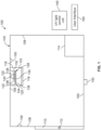
- FIG. 1 illustrates a schematic diagram of a UV light sanitizing system 100 for an enclosed space 102, according to the present disclosure.
- the enclosed space 102 may be defined by a floor 104, a ceiling 106, and walls 108 extending between the floor 104 and the ceiling 106.
- a door 110 may be moveably secured to one of the walls 108.
- the door 110 may include a lock 112 that is configured to securely lock the door 110 in a closed position. When the lock 112 is in a locked position, the door 110 is unable to be opened. When the lock 112 is in an unlocked position, the door 110 may be opened.
- the enclosed space 102 may be a confined space onboard a commercial aircraft. For example, the enclosed space 102 may be a lavatory onboard an aircraft.
- the enclosed space 102 may be a galley onboard an aircraft. As yet another example, the enclosed space 102 may be a passenger area onboard an aircraft. The enclosed space 102 may or may not include the door 110. The enclosed space 102 may be within various other vehicles, structures, and/or the like. For example, the enclosed space 102 may be a room within a commercial, municipal, or residential building, or a room onboard a train, bus, ship, or the like.
- the enclosed space 102 may include at least one component 114 to be sanitized (for example, disinfected, sterilized, or otherwise cleaned) after use.
- the component 114 may be a toilet, sink, floor, cabinet, and/or the like within a lavatory of an aircraft.
- the UV light sanitizing system 100 includes a lighting assembly 116, which may be secured to the ceiling 106.
- the lighting assembly 116 may extend below the ceiling 106.
- a light outlet passage 118 (such as an open end, aperture, clear window, or the like) can be flush with or recessed within a lower surface of the ceiling 106.
- the lighting assembly 116 may be secured to (or supported by) various other structures of the enclosed space 102, such as the floor 104, walls 108, a portion of the component 114, or the like.
- the lighting assembly 116 includes a housing 120, which may include opaque outer walls 122 connected to the light outlet passage 118.
- a light source 124 is secured within the housing 120.
- the light source 124 is configured to emit light 126 at a first frequency, such as ultraviolet light.
- the lighting assembly 116 also includes a light converter 128.
- the light converter 128 includes an optically-transparent substrate 130 (such as a transparent plastic, glass, or the like panel) that is coupled to a phosphor layer 132.
- the phosphor layer 132 may be secured over or under the substrate 130.
- the phosphor layer 132 may coat an entirety of the substrate 130.
- the phosphor layer 132 may coat an upper or lower surface of the substrate 130.
- the phosphor layer 132 may be dispersed throughout the substrate 130 (for example, mixed into the substrate 130).
- the substrate 130 may be one or more transparent pieces of plastic or glass, and the phosphor layer 132 may be disposed within the substrate 130, such as within an interior channel, thereby protecting the phosphor layer 132 from dust, dirt, debris, and damage.
- the light converter 128 is coupled to an actuator 134, which may be contained within, secured to an outer portion of, or remotely located from the housing 120.
- the actuator 134 is configured to move the light converter 128 between a first position, in which the light converter 128 is within a light emission path 136 of the light source 124, and a second position, in which the light converter 128 is outside of the light emission path 136 of the light source 124.
- the actuator 134 may connect to the light converter 128 through a link 138 that allows the actuator 134 to move the light converter 128 between the first and second positions.
- the actuator 134 may be an electric motor, a pneumatic motor, a hydraulic motor, one or more solenoids, one or more pistons, and/or the like.
- the actuator 134 may be configured to rotate the light converter 128 between the first and second positions.
- the actuator 134 may be configured to pivot the light converter 128 between the first and second positions.
- the actuator 134 may be configured to linearly move the light converter 128 between the first and second positions.
- the actuator 134 may be operatively coupled to the light source 124, while the light converter 128 remains in a fixed position within the housing 120.
- the actuator 134 can be configured to move the light source 124 between first and second positions relative to the light converter 128.
- the lightning system 116 may be controlled by a UV light control unit 140.
- the UV light control unit 140 may be in communication with the actuator 134 and the light source 124 such as through wired or wireless connections.
- the UV light control unit 140 may be positioned within or connected to the enclosed space 102, or may be remotely located therefrom.
- the UV light control unit 140 can be housed within the lighting assembly 116.
- the UV light control unit 140 is configured to control operation of the lighting assembly 116 to selectively emit sanitizing UV light into the enclosed space and illuminating visible light that illuminates an interior of the enclosed space 102.
- the UV light control unit 140 operates the actuator 134 to move the light converter 128 outside of a light emission path 136 of the UV light source 124, which emits the UV light 126. As such, UV light passes through the light outlet passage 118 and onto the component 114. Upon completion of the sanitizing cycle, the UV light control unit 140 operates the actuator 134 to move the light converter 128 back within the light emission path 136 of the UV light source 124.
- the light converter 128 When the light converter 128 is disposed within the light emission path 136, the light converter 128 down-converts the UV light 126 emitted from the UV light source 124 to a lower frequency. In particular, as the UV light 126 impinges on the light converter 128, the UV light 126 excites the phosphor layer 132 to a higher energy state. In the process, the UV light 126 passing through the light converter loses energy, and is converted to lower frequency visible light, which safely and efficiently illuminates the interior of the enclosed space 102 without the need for an additional visible light source.
- the light source 124 may include one or more UV light elements, such as an arc lamp(s), laser(s), light emitting diode(s) (LEDs), microfilament(s), fiber optic element(s), bulb(s), and/or the like.
- the light source 124 can emit the UV light 126 as far UV light that is used to sanitize the component 114.
- the UV light 126 may be UVA light, UVB light, UVC light, vacuum UV light, or the like.
- the light source 124 may include UV light elements that are configured to emit UV light with different UV bands (for example, at different wavelengths and different frequencies). For example, one UV light element may be configured to emit far UV light, while another UV light element may be configured to emit UVC light.
- the presence sensors 150 may be secured within the enclosed space 102.
- the presence sensors 150 may be ultrasound sensors, infrared sensors, thermal sensors, weight sensors (for example, weight scales), and/or the like that are configured to detect the presence of an individual within the enclosed space 102.
- At least one presence sensor 150 may be a digital scale that detects the presence of an individual through a discernable detection of mass or weight within the enclosed space 102.
- the presence sensors 150 are in communication with the UV light control unit 140 through one or more wired or wireless connections. Based on presence signals received from the presence sensors 150, the UV light control unit 140 determines whether or not an individual is within the enclosed space 102.
- the UV light control unit 140 determines that an individual is within the enclosed space, the UV light control unit 140 refrains from operating the lighting assembly 116 to emit sanitizing UV light into the enclosed space. Instead, when an individual is within the enclosed space, the UV light control unit 140 ensures that the light converter 128 is within the light emission path 136 of the light source 124, which down-converts the emitted UV light into visible light (as described above), thereby safely illuminating the interior of the enclosed space 102.
- the enclosed space 102 may not include the presence sensors 150.
- the UV light control unit 140 may be configured to determine that the enclosed space is unoccupied, such as by being in communication with the lock 112 and/or the component 114. For example, the UV light control unit 140 may determine that the enclosed space 102 is unoccupied when the door 110 is locked.
- the UV light control unit 140 may initiate a sanitizing cycle based on a sequence of events, which may be triggered by the component 114 being used, the door being unlocked, and the door being subsequently closed. During the sanitizing cycle, the UV light control unit 140 may ensure that the door 110 is locked, so that individuals may not enter the enclosed space 102.
- the UV light control unit 140 moves the light converter 128 back into the light emission path 136 of the light source 124 so that light emitted from the light source 124 is down-converted by the phosphor layer 132 into safe, visible light, and then the UV light control unit 140 unlocks the door 110. If the door 110 is opened, and/or the presence sensors 150 detect the presence of an individual within the enclosed space 102 during a sanitizing cycle, the UV light control unit 140 may immediately move the light converter 128 into the light emission path 136, and/or deactivate the light source 124.
- the UV light control unit 140 may initiate the sanitizing cycle after each use of the enclosed space 102 (such as after each time the door 110 is locked and unlocked, and/or after each time the presence sensors 150 detect that an individual has left the enclosed space 102).
- the sanitizing cycle may be initiated after a predetermined number of uses of the enclosed space 102, such as after each second, third, fourth, fifth, or nth use.
- the UV light control unit 140 may also be in communication with a user interface 160, such as a computing device (for example, a computer, handheld smart device, dedicated control panel, or the like) that allows an individual (such as a flight attendant onboard an aircraft) to initiate the sanitizing cycle.
- a user interface 160 such as a computing device (for example, a computer, handheld smart device, dedicated control panel, or the like) that allows an individual (such as a flight attendant onboard an aircraft) to initiate the sanitizing cycle.
- the UV light sanitizing system 100 may not include the user interface 160.
- the UV light sanitizing system 100 may include two, three, four, or more lighting assemblies in communication with the UV light control unit 140.
- Each lighting assembly may be configured to sanitize a different (or the same) surface within the enclosed space 102.
- one lighting assembly 116 may be configured to sanitize a surface of a toilet
- another UV light assembly may be configured to sanitize a sink
- another lighting assembly may be configured to sanitize at least a portion of the floor 104.
- the lighting assembly 116 may be used in various other settings.
- the light source 124 may be configured to emit light at a different frequency than UV light.
- the light source 124 may be configured to emit visible light
- the phosphor layer 132 may convert the emitted visible light to a lower frequency, such as infrared light.
- the lighting assembly 116 may be used with respect to applications other than sanitation.
- the lighting assembly 116 may be used to selectively convert visible light to infrared light with respect to night vision goggles.
- control unit central processing unit
- CPU central processing unit
- CPU central processing unit
- CPU central processing unit
- CPU central processing unit
- CPU central processing unit
- ASIC application specific integrated circuits
- logic circuits any other circuit or processor including hardware, software, or a combination thereof capable of executing the functions described herein.
- UV light control unit 140 may be or include one or more processors that are configured to control operation of the lighting assembly 116, as described above.
- the UV light control unit 140 is configured to execute a set of instructions that are stored in one or more data storage units or elements (such as one or more memories), in order to process data.
- the UV light control unit 140 may include or be coupled to one or more memories.
- the data storage units may also store data or other information as desired or needed.
- the data storage units may be in the form of an information source or a physical memory element within a processing machine.
- the set of instructions may include various commands that instruct the UV light control unit 140 as a processing machine to perform specific operations such as the methods and processes of the subject matter described herein.
- the set of instructions may be in the form of a software program.
- the software may be in various forms such as system software or application software. Further, the software may be in the form of a collection of separate programs, a program subset within a larger program, or a portion of a program.
- the software may also include modular programming in the form of object-oriented programming.
- the processing of input data by the processing machine may be in response to user commands, or in response to results of previous processing, or in response to a request made by another processing machine.
- the diagrams herein may illustrate one or more control or processing units, such as the UV light control unit 140.
- the processing or control units may represent circuits, circuitry, or portions thereof that may be implemented as hardware with associated instructions (e.g., software stored on a tangible and non-transitory computer readable storage medium, such as a computer hard drive, ROM, RAM, or the like) that perform the operations described herein.
- the hardware may include state machine circuitry hardwired to perform the functions described herein.
- the hardware may include electronic circuits that include and/or are connected to one or more logic-based devices, such as microprocessors, processors, controllers, or the like.
- the UV light control unit 140 may represent processing circuitry such as one or more of a field programmable gate array (FPGA), application specific integrated circuit (ASIC), microprocessor(s), and/or the like.
- the circuits may be configured to execute one or more algorithms to perform functions described herein.
- the one or more algorithms may include aspects disclosed herein, whether or not expressly identified in a flowchart or a method.
- the terms "software” and “firmware” are interchangeable, and include any computer program stored in a data storage unit (for example, one or more memories) for execution by a computer, including RAM memory, ROM memory, EPROM memory, EEPROM memory, and non-volatile RAM (NVRAM) memory.
- a data storage unit for example, one or more memories
- NVRAM non-volatile RAM
- the above data storage unit types are exemplary only, and are thus not limiting as to the types of memory usable for storage of a computer program.
- FIG. 2 illustrates a block diagram of the lighting assembly 116, according to the present disclosure.
- the lighting assembly 116 includes the housing 120, which contains the light source 124.
- the light source 124 emits light 126 at a first frequency.
- the actuator 134 is operatively coupled to one of the light converter 128 or the light source 124 to selectively move the light converter 128 relative to the light source 124.
- the light converter 128 is outside of the light emission path 126 of the light source 124, the light 126 at the first frequency passes through the light outlet passage 118.
- the light converter 128 When the light converter 128 is within the light emission path 126, the light converter 128 down-converts the emitted light from the first frequency to a second frequency that is lower than the first frequency, which then passes through the light outlet passage 118.
- the light converter 128 may be positioned within the housing 120 between the light source 124 and the light outlet passage 118.
- the light converter 128 may be disposed over the light outlet passage 118 when the light converter 128 is within the light emission path 126.
- the light converter 128 may underlay the light outlet passage 118.
- FIG 3 illustrates a flow chart of a method of using a lighting assembly to sanitize a component within a confined space, such as a lavatory, according to the present disclosure.
- the method begins at 200, at which the UV light control unit 140 operates the actuator 134 to dispose the light converter 128 within the light emission path 136 of the UV light source 124.
- the light control unit 140 activates the UV light source 124.
- UV light 126 is emitted from the activated UV light source 124.
- the UV light control unit 140 determines whether the lavatory 102 is occupied. If the lavatory 102 is occupied, the method proceeds from 206 to 208, at which the UV light control unit 140 maintains the light converter 128 within the light emission path 136 of the UV light source 124. At 210, visible light is generated within the lavatory 102 through interaction of the emitted UV light 126 passing through the light converter 128. In particular, as the UV light 126 passes through the phosphor layer 132 of the light converter 128, the UV light 126 is down-converted into lower frequency visible light. At 212, the interior of the lavatory 102 is illuminated with the generated visible light. The method then returns to 204.
- the method proceeds to 214, at which the UV light control unit 140 determines whether the component 114 is to be sanitized. If the component 114 is not in need of sanitation, the method proceeds to 208.
- the method proceeds from 214 to 216, at which the UV light control unit 140 moves the light converter 128 out of the light emission path 136 of the light source 124.
- the UV light 126 emitted from the UV light source 124 passes through the lighting assembly 116 unimpeded, and is emitted onto the component 114 at 218, thereby sanitizing the component 114.
- the UV light control unit 140 determines whether the sanitizing cycle is complete. If the sanitizing cycle is not complete, the method returns to 218. If, however, the sanitizing cycle is complete, the method returns to 200 from 220.
- Figure 4 illustrates a top view of an actuator 134 coupled to a light converter 128, according to the present disclosure.
- the link 138 that securely connects the actuator 134 to the light converter 128 may be one or more of a bracket(s), beam(s), clamp(s), and/or the like.
- the actuator 134 is configured to rotate the light converter 128 about a vertical axis 135 of the actuator 134 in the directions of arc A between a first position 300, in which the light converter 128 is underneath the light source 124 within a light emission path, and a second position 302, in which the light converter 128 is outside of the light emission path.
- Figure 5 illustrates a top view of an actuator 134 coupled to a light converter 128, according to the present disclosure.
- the link 138 that securely connects the actuator 134 to the light converter 128 may be a track and rail system, for example.
- the actuator 134 is configured to push and pull the light converter 128 along the link 138 in the directions of line B between a first position, in which the light converter 128 is underneath the light source 124 within a light emission path, and a second position, in which the light converter 128 is outside of the light emission path.
- Figure 6 illustrates a top view of an actuator 134 coupled to a light source 124, according to the present disclosure.
- Figure 6 is similar to that of Figure 4 , except that the actuator 134 is operatively coupled to the light source 124, while the light converter 128 remains fixed in place.
- Figure 7 illustrates a top view of an actuator 134 coupled to a light source 124, according to the present disclosure.
- Figure 7 is similar to that of Figure 5 , except that the actuator 134 is operatively coupled to the light source 124, while the light converter 128 remains fixed in place.
- Figure 8 illustrates a lateral view of an actuator 134 coupled to a light converter 128, according to the present disclosure.
- the actuator 134 can be configured to pivot the light converter between first and second positions about a horizontal axis 137.
- FIG 13 illustrates a perspective bottom view of a lighting assembly 116, according to the present disclosure.
- the light source 124 may include a UV-generating light bulb, such as an excimer light bulb.
- the light source 124 is positioned above an outwardly-bowed light converter 128, such as an arcuate sheet of phosphor-coated glass.
- the light converter 128 is coupled to a pivot axle 800 having a longitudinal axis that is parallel with a longitudinal axis of the light source 124.
- An actuator is configured to rotate the light converter 128 about the longitudinal axis of the pivot axle 800 in the directions of arc 802.
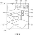
- Figure 9 illustrates a perspective internal view of a lavatory 102, according to the present disclosure.
- the lavatory 102 is the enclosed space 102 shown and described with respect to Figure 1 .
- the lavatory 102 may be onboard an aircraft, as described above.
- the lavatory 102 may be onboard various other vehicles.
- the lavatory 102 includes the floor 104 that supports a toilet 400, cabinets 402, and a sink 404.
- Lighting assemblies 116 are secured within the lavatory 102 and are configured to be activated during a sanitizing cycle to sanitize (for example, disinfect, sterilize, or otherwise clean) various structures within the lavatory 102, such as the toilet 400, the floor 104, the cabinets 402, and/or the sink 404.
- the presence sensors 130 may be secured to portions of the lavatory 102.
- the lighting assemblies 116 are operated to emit visible light to safely illuminate the interior of the lavatory 102, as described above.
- the lighting assemblies 116 are operated to emit sanitizing UV light, as described above.
- FIG 10 illustrates a perspective front view of an aircraft 600, according to the present disclosure.
- the aircraft 600 includes a propulsion system 612 that may include two turbofan engines 614, for example.
- the propulsion system 612 may include more engines 614 than shown.
- the engines 614 are carried by wings 616 of the aircraft 600.
- the engines 614 may be carried by a fuselage 618 and/or an empennage 620.
- the empennage 620 may also support horizontal stabilizers 622 and a vertical stabilizer 624.
- the fuselage 618 of the aircraft 600 defines an internal cabin, which may include a cockpit, one or more work sections (for example, galleys, personnel carry-on baggage areas, and the like), one or more passenger sections (for example, first class, business class, and coach sections), and an aft section in which an aft rest area assembly may be positioned. Each of the sections may be separated by a cabin transition area, which may include one or more class divider assemblies. Overhead stowage bin assemblies may be positioned throughout the internal cabin.
- the internal cabin includes one or more chambers, such as lavatories, for example.
- One or more UV light sanitizing systems 100 may be located within the internal cabin.
- the present disclosure may be used with various other vehicles, such as automobiles, buses, locomotives and train cars, watercraft, and the like.
- FIG 11 illustrates a top plan view of an internal cabin 630 of an aircraft, according to the present disclosure.
- the internal cabin 630 may be within a fuselage 632 of the aircraft.
- one or more fuselage walls may define the internal cabin 630.
- the internal cabin 630 includes multiple sections, including a front section 633, a first class section 634 (or first class suites, cabins, for example), a business class section 636, a front galley station 638, an expanded economy or coach section 640, a standard economy or coach section 642, and an aft section 644, which may include multiple enclosed spaces or chambers 102, such as lavatories and galley stations.
- the internal cabin 630 may include more or less sections than shown.
- the internal cabin 630 may not include a first class section, and may include more or less galley stations than shown.
- Each of the sections may be separated by a cabin transition area 646, which may include class divider assemblies between aisles 648.
- the internal cabin 630 includes two aisles 650 and 652 that lead to the aft section 644.
- the internal cabin 630 may have less or more aisles than shown.
- the internal cabin 630 may include a single aisle that extends through the center of the internal cabin 630 that leads to the aft section 644.
- One or more enclosed spaces 102 such as lavatories, may be located within the internal cabin 630.
- UV light sanitizing systems 100 may be used to sanitize structures within the lavatories 102, such as described above.
- Figure 12 illustrates a top plan view of an internal cabin 680 of an aircraft, according to an embodiment of the present disclosure.
- the internal cabin 680 may be within a fuselage 681 of the aircraft.
- one or more fuselage walls may define the internal cabin 680.
- the internal cabin 680 includes multiple sections, including a main cabin 682 having passenger seats 683, and an aft section 685 behind the main cabin 682. It is to be understood that the internal cabin 680 may include more or less sections than shown.
- the internal cabin 680 may include a single aisle 684 that leads to the aft section 685.
- the single aisle 684 may extend through the center of the internal cabin 680 that leads to the aft section 685.
- the single aisle 684 may be coaxially aligned with a central longitudinal plane of the internal cabin 680.
- One or more enclosed spaces 102 may be located within the internal cabin 680.
- UV light sanitizing systems 100 may be used to sanitize structures within the lavatories 102, such as described above.
- the present disclosure provide systems and methods for efficiently and effectively sanitizing a surface of a component.
- the present disclosure may provide systems and methods for operating a UV light assembly to sanitize a component without interfering with use of the component by an individual. Further, the present disclosure provides systems and methods for efficiently and effectively incorporating a UV light assembly into a confined space of an aircraft lavatory.
- a single lighting assembly may be used to selectively emit sanitizing UV light and illuminating visible light.
- a light converter is used to selectively convert the UV light into visible light. In this manner, less material is used to construct the lavatory, which saves costs and reduces an overall weight of the lavatory (and therefore an aircraft into which the lavatory is positioned).
- a structure, limitation, or element that is "configured to” perform a task or operation is particularly structurally formed, constructed, or adapted in a manner corresponding to the task or operation.
- an object that is merely capable of being modified to perform the task or operation is not “configured to” perform the task or operation as used herein.
Landscapes
- Health & Medical Sciences (AREA)
- Engineering & Computer Science (AREA)
- General Health & Medical Sciences (AREA)
- Public Health (AREA)
- Veterinary Medicine (AREA)
- Epidemiology (AREA)
- Life Sciences & Earth Sciences (AREA)
- Animal Behavior & Ethology (AREA)
- Aviation & Aerospace Engineering (AREA)
- General Engineering & Computer Science (AREA)
- Physics & Mathematics (AREA)
- Spectroscopy & Molecular Physics (AREA)
- Manufacturing & Machinery (AREA)
- Transportation (AREA)
- Apparatus For Disinfection Or Sterilisation (AREA)
- Mechanical Engineering (AREA)
- Non-Portable Lighting Devices Or Systems Thereof (AREA)
Claims (15)
- Fahrzeug mit einer Toilette (102), umfassend:eine Beleuchtungsanordnung (116), die dazu konfiguriert ist, Licht (126) mit einer ersten Frequenz und Licht (126) mit einer zweiten Frequenz wahlweise zu emittieren, wobei die Beleuchtungsanordnung (116) Folgendes umfasst:eine Lichtquelle (124), die dazu konfiguriert ist, das Licht (126) mit der ersten Frequenz über einen Lichtemissionsweg (136) zu emittieren,einen Lichtwandler (128); undeinen Aktuator (134), der mit einem aus Lichtquelle (124) und Lichtwandler (128) wirkverbunden ist, wobei der Aktuator (134) dazu konfiguriert ist, eines aus Lichtwandler (128) und Lichtquelle (124) relativ zum anderen aus Lichtwandler (128) und Lichtquelle (124) zwischen einer ersten Position und einer zweiten Position zu bewegen, wobei sich das Lichtwandler (128) in der ersten Position innerhalb des Lichtemissionswegs (136) und in der zweiten Position außerhalb von dem Lichtemissionsweg (136) befindet, wobei das Lichtwandler (128) in der ersten Position das Licht (126) mit der ersten Frequenz in das Licht (126) mit der zweiten Frequenz umwandelt, und wobei das Licht (126) mit der ersten Frequenz aus der Beleuchtungsanordnung (116) emittiert wird, wenn sich das Lichtwandler (128) in der zweiten Position befindet,wobei die zweite Frequenz niedriger als die erste Frequenz ist,wobei das Lichtwandler (128) ein optisch transparentes Substrat und eine Leuchtstoffschicht umfasst, wobei die Leuchtstoffschicht dazu konfiguriert ist, das Licht (126) mit der ersten Frequenz in das Licht (126) mit der zweiten Frequenz herunterzuwandeln.
- Fahrzeug nach Anspruch 1, wobei das Licht (126) mit der ersten Frequenz ultraviolettes (UV) Licht (126) ist, und wobei das Licht (126) mit der zweiten Frequenz sichtbares Licht (126) ist.
- Fahrzeug nach Anspruch 1 oder 2, wobei der Aktuator (134) mit dem Lichtwandler (128) wirkverbunden ist, und wobei die Lichtquelle (124) fixiert ist.
- Fahrzeug nach Anspruch 1, 2 oder 3, wobei der Aktuator (134) mit der Lichtquelle (124) wirkverbunden ist, und wobei das Lichtwandler (128) fixiert ist.
- Fahrzeug nach einem der Ansprüche 1 bis 4, wobei der Aktuator (134) dazu konfiguriert ist, eines aus Lichtwandler (128) und Lichtquelle (124) relativ zum anderen aus Lichtwandler (128) und Lichtquelle (124) drehbar zu bewegen.
- Fahrzeug nach einem der Ansprüche 1 bis 5, wobei der Aktuator (134) dazu konfiguriert ist, eines aus Lichtwandler (128) und Lichtquelle (124) relativ zum anderen aus Lichtwandler (128) und Lichtquelle (124) linear zu bewegen.
- Fahrzeug nach einem der Ansprüche 1 bis 6, wobei der Aktuator (134) dazu konfiguriert ist, eines aus Lichtwandler (128) und Lichtquelle (124) relativ zum anderen aus Lichtwandler (128) und Lichtquelle (124) schwenkbar zu bewegen.
- Fahrzeug nach einem der Ansprüche 1 bis 7, wobei die Leuchtstoffschicht zumindest einen Teil des Substrats beschichtet.
- Fahrzeug nach einem der Ansprüche 1 bis 8, wobei die Leuchtstoffschicht in dem Substrat verteilt ist.
- Fahrzeug nach einem der Ansprüche 1 bis 9, wobei die Leuchtstoffschicht innerhalb des Substrats geschützt ist.
- Fahrzeug nach einem der Ansprüche 1 bis 10, wobei die Lichtquelle (124) ein oder mehrere UV-Lichtelemente umfasst, wie etwa Bogenlampen, Laser, Leuchtdioden (LEDs), Mikrofilamente, Faseroptikelemente, Glühbirnen und dergleichen umfasst.
- Fahrzeug nach einem der Ansprüche 1 bis 11, wobei die Lichtquelle (124) die UV-Licht (126) als fernes UV-Licht emittiert.
- Fahrzeug nach einem der Ansprüche 1 bis 11, wobei das UV-Licht (126) UVA-Licht, UVB-Licht, UVC-Licht, Vakuum-UV-Licht oder dergleichen ist.
- Fahrzeug nach einem der Ansprüche 1 bis 13, wobei die Lichtquelle (124) UV-Lichtelement umfasst, die dazu konfiguriert sind, UV-Licht mit unterschiedlichen UV-Bändern zu emittieren.
- Fahrzeug nach einem der Ansprüche 1 bis 14, wobei es sich um ein Flugzeug handelt.
Applications Claiming Priority (1)
| Application Number | Priority Date | Filing Date | Title |
|---|---|---|---|
| US15/413,495 US10655818B2 (en) | 2017-01-24 | 2017-01-24 | Light-converting lighting assembly |
Publications (2)
| Publication Number | Publication Date |
|---|---|
| EP3351272A1 EP3351272A1 (de) | 2018-07-25 |
| EP3351272B1 true EP3351272B1 (de) | 2023-04-05 |
Family
ID=60627407
Family Applications (1)
| Application Number | Title | Priority Date | Filing Date |
|---|---|---|---|
| EP17203770.7A Active EP3351272B1 (de) | 2017-01-24 | 2017-11-27 | Frahzeug mit toilettenkabine die eine lichtkonvertierende beleuchtungsanordnung umfasst |
Country Status (3)
| Country | Link |
|---|---|
| US (1) | US10655818B2 (de) |
| EP (1) | EP3351272B1 (de) |
| CN (1) | CN108343871A (de) |
Families Citing this family (15)
| Publication number | Priority date | Publication date | Assignee | Title |
|---|---|---|---|---|
| EP3937991A4 (de) * | 2019-03-12 | 2022-12-14 | Visser, Johann Cornelius | Sterilisator für prothesezubehör |
| CN110133915A (zh) * | 2019-05-30 | 2019-08-16 | 上海中航光电子有限公司 | 显示装置 |
| CN110303009B (zh) * | 2019-06-26 | 2020-10-16 | 深圳市华星光电技术有限公司 | 紫外光清洁装置 |
| US20210024196A1 (en) * | 2019-07-25 | 2021-01-28 | Gulfstream Aerospace Corporation | Aircraft, interior panels for aircfraft, and methods for making interior panels |
| US11427326B2 (en) * | 2020-02-27 | 2022-08-30 | Mirza Faizan | Automated aircraft tray table disinfecting system using ultra-violet light |
| CN111467521B (zh) * | 2020-04-14 | 2022-03-29 | 深圳市格物致新科技有限公司 | 厕所蹲位杀菌控制方法、系统及存储介质 |
| US11116858B1 (en) | 2020-05-01 | 2021-09-14 | Uv Innovators, Llc | Ultraviolet (UV) light emission device employing visible light for target distance guidance, and related methods of use, particularly suited for decontamination |
| US11938234B2 (en) * | 2020-06-08 | 2024-03-26 | The Boeing Company | Visible light sanitizing systems and methods |
| US20210393823A1 (en) * | 2020-06-23 | 2021-12-23 | The Boeing Company | Sanitizing system |
| TWI755814B (zh) * | 2020-08-12 | 2022-02-21 | 許武一 | 具有自動切換消毒殺菌功能的照明燈系統 |
| US12106956B2 (en) | 2021-05-18 | 2024-10-01 | B/E Aerospace, Inc. | Color mixed excimer lamp for soft glow effect |
| US20220387641A1 (en) * | 2021-06-07 | 2022-12-08 | The Boeing Company | Systems and methods for sanitizing portions of an enclosed space and allocating sanitizing resources within the enclosed space |
| CN113844644A (zh) * | 2021-11-08 | 2021-12-28 | 广东国志激光技术有限公司 | 一种室外飞行器激光消毒无人机 |
| JP2023119620A (ja) * | 2022-02-17 | 2023-08-29 | ウシオ電機株式会社 | 不活化処理方法、不活化処理システム |
| JP2023124498A (ja) * | 2022-02-25 | 2023-09-06 | ウシオ電機株式会社 | 菌又はウイルスの不活化装置 |
Citations (1)
| Publication number | Priority date | Publication date | Assignee | Title |
|---|---|---|---|---|
| US20100320405A1 (en) * | 2008-02-07 | 2010-12-23 | Gardner Iii William G | Handheld portable multi purpose sterilizing wavelength transforming converter |
Family Cites Families (15)
| Publication number | Priority date | Publication date | Assignee | Title |
|---|---|---|---|---|
| US4819276A (en) | 1987-03-26 | 1989-04-11 | Stevens Robert B | Germicidal toilet seat |
| JPH07289616A (ja) | 1994-04-21 | 1995-11-07 | Fujita Corp | 殺菌線の照射方法および照射装置 |
| US7485883B2 (en) * | 2003-12-19 | 2009-02-03 | Gardner Iii William G | Variable wavelength radiation source |
| CN101496452A (zh) * | 2006-10-18 | 2009-07-29 | 夏普株式会社 | 照明装置及液晶显示装置 |
| KR100979702B1 (ko) * | 2008-06-27 | 2010-09-03 | 서울반도체 주식회사 | 전환형 발광장치 |
| US8761565B1 (en) | 2009-04-16 | 2014-06-24 | Fusion Optix, Inc. | Arcuate lightguide and light emitting device comprising the same |
| EP2606275A2 (de) * | 2010-08-20 | 2013-06-26 | Research Triangle Institute, International | Farbabstimmbare beleuchtungsvorrichtungen und verfahren zur abstimmung der farbausgabe von beleuchtungsvorrichtungen |
| CN102374412A (zh) * | 2010-08-26 | 2012-03-14 | 邱行中 | 发光装置及照明装置 |
| GB2527964B (en) | 2012-01-30 | 2016-03-02 | Xenex Disinfection Services Llc | Ultraviolet discharge lamp apparatuses with multi-paneled optical filters |
| WO2014036217A2 (en) | 2012-08-29 | 2014-03-06 | Mag Aerospace Industries, Inc. | Aircraft galley and lavatory disinfection |
| US20140115764A1 (en) | 2012-10-25 | 2014-05-01 | Ying Chang Cheng | The sanitization mechanism of the toilet seat |
| EP3237857B1 (de) | 2014-12-22 | 2023-06-14 | Elevated Health Systems, LLC | Keimtötendes uv-licht-desinfektionssystem |
| US9623133B2 (en) | 2015-01-30 | 2017-04-18 | The Boeing Company | Lavatory disinfection system |
| US9783974B1 (en) * | 2016-08-09 | 2017-10-10 | The Boeing Company | Fluid removal systems and methods |
| US9993571B2 (en) * | 2016-08-24 | 2018-06-12 | The Boeing Company | Multi-wavelength ultraviolet light sanitizing systems and methods |
-
2017
- 2017-01-24 US US15/413,495 patent/US10655818B2/en active Active
- 2017-11-27 EP EP17203770.7A patent/EP3351272B1/de active Active
- 2017-12-06 CN CN201711274992.7A patent/CN108343871A/zh active Pending
Patent Citations (1)
| Publication number | Priority date | Publication date | Assignee | Title |
|---|---|---|---|---|
| US20100320405A1 (en) * | 2008-02-07 | 2010-12-23 | Gardner Iii William G | Handheld portable multi purpose sterilizing wavelength transforming converter |
Also Published As
| Publication number | Publication date |
|---|---|
| US10655818B2 (en) | 2020-05-19 |
| CN108343871A (zh) | 2018-07-31 |
| EP3351272A1 (de) | 2018-07-25 |
| US20180209613A1 (en) | 2018-07-26 |
Similar Documents
| Publication | Publication Date | Title |
|---|---|---|
| EP3351272B1 (de) | Frahzeug mit toilettenkabine die eine lichtkonvertierende beleuchtungsanordnung umfasst | |
| EP3293118B1 (de) | Ausklappbare ultraviolettlichtdesinfektionssysteme und -verfahren | |
| US10413622B2 (en) | Systems and methods for sanitizing a tray table | |
| US10772981B2 (en) | Disinfection system | |
| US9993571B2 (en) | Multi-wavelength ultraviolet light sanitizing systems and methods | |
| EP4032808B1 (de) | Systeme und verfahren zur erkennung der belegung von toiletten | |
| EP3449948B1 (de) | Ozonzerstörende ultraviolettlichtreinigungssysteme und verfahren | |
| CA2973848C (en) | Ozone ventilation systems and methods | |
| US11938234B2 (en) | Visible light sanitizing systems and methods | |
| JP2022064872A (ja) | 紫外線殺菌システムおよび方法 | |
| EP4180062A2 (de) | Systeme und verfahren zur desinfektion von händen | |
| CN114533927A (zh) | 紫外光消毒系统和方法 | |
| CN114544147A (zh) | 使紫外线灯对准的系统和方法 |
Legal Events
| Date | Code | Title | Description |
|---|---|---|---|
| PUAI | Public reference made under article 153(3) epc to a published international application that has entered the european phase |
Free format text: ORIGINAL CODE: 0009012 |
|
| STAA | Information on the status of an ep patent application or granted ep patent |
Free format text: STATUS: REQUEST FOR EXAMINATION WAS MADE |
|
| 17P | Request for examination filed |
Effective date: 20171127 |
|
| AK | Designated contracting states |
Kind code of ref document: A1 Designated state(s): AL AT BE BG CH CY CZ DE DK EE ES FI FR GB GR HR HU IE IS IT LI LT LU LV MC MK MT NL NO PL PT RO RS SE SI SK SM TR |
|
| AX | Request for extension of the european patent |
Extension state: BA ME |
|
| STAA | Information on the status of an ep patent application or granted ep patent |
Free format text: STATUS: EXAMINATION IS IN PROGRESS |
|
| 17Q | First examination report despatched |
Effective date: 20190522 |
|
| STAA | Information on the status of an ep patent application or granted ep patent |
Free format text: STATUS: EXAMINATION IS IN PROGRESS |
|
| GRAP | Despatch of communication of intention to grant a patent |
Free format text: ORIGINAL CODE: EPIDOSNIGR1 |
|
| STAA | Information on the status of an ep patent application or granted ep patent |
Free format text: STATUS: GRANT OF PATENT IS INTENDED |
|
| INTG | Intention to grant announced |
Effective date: 20210317 |
|
| GRAJ | Information related to disapproval of communication of intention to grant by the applicant or resumption of examination proceedings by the epo deleted |
Free format text: ORIGINAL CODE: EPIDOSDIGR1 |
|
| STAA | Information on the status of an ep patent application or granted ep patent |
Free format text: STATUS: EXAMINATION IS IN PROGRESS |
|
| INTC | Intention to grant announced (deleted) | ||
| STAA | Information on the status of an ep patent application or granted ep patent |
Free format text: STATUS: EXAMINATION IS IN PROGRESS |
|
| GRAP | Despatch of communication of intention to grant a patent |
Free format text: ORIGINAL CODE: EPIDOSNIGR1 |
|
| STAA | Information on the status of an ep patent application or granted ep patent |
Free format text: STATUS: GRANT OF PATENT IS INTENDED |
|
| INTG | Intention to grant announced |
Effective date: 20220914 |
|
| RIN1 | Information on inventor provided before grant (corrected) |
Inventor name: CALLAHAN, KEVIN S. |
|
| GRAJ | Information related to disapproval of communication of intention to grant by the applicant or resumption of examination proceedings by the epo deleted |
Free format text: ORIGINAL CODE: EPIDOSDIGR1 |
|
| STAA | Information on the status of an ep patent application or granted ep patent |
Free format text: STATUS: EXAMINATION IS IN PROGRESS |
|
| GRAS | Grant fee paid |
Free format text: ORIGINAL CODE: EPIDOSNIGR3 |
|
| STAA | Information on the status of an ep patent application or granted ep patent |
Free format text: STATUS: GRANT OF PATENT IS INTENDED |
|
| GRAP | Despatch of communication of intention to grant a patent |
Free format text: ORIGINAL CODE: EPIDOSNIGR1 |
|
| INTC | Intention to grant announced (deleted) | ||
| INTG | Intention to grant announced |
Effective date: 20230126 |
|
| GRAA | (expected) grant |
Free format text: ORIGINAL CODE: 0009210 |
|
| STAA | Information on the status of an ep patent application or granted ep patent |
Free format text: STATUS: THE PATENT HAS BEEN GRANTED |
|
| RAP3 | Party data changed (applicant data changed or rights of an application transferred) |
Owner name: THE BOEING COMPANY |
|
| AK | Designated contracting states |
Kind code of ref document: B1 Designated state(s): AL AT BE BG CH CY CZ DE DK EE ES FI FR GB GR HR HU IE IS IT LI LT LU LV MC MK MT NL NO PL PT RO RS SE SI SK SM TR |
|
| REG | Reference to a national code |
Ref country code: GB Ref legal event code: FG4D |
|
| REG | Reference to a national code |
Ref country code: CH Ref legal event code: EP |
|
| REG | Reference to a national code |
Ref country code: AT Ref legal event code: REF Ref document number: 1557762 Country of ref document: AT Kind code of ref document: T Effective date: 20230415 |
|
| REG | Reference to a national code |
Ref country code: DE Ref legal event code: R096 Ref document number: 602017067395 Country of ref document: DE |
|
| REG | Reference to a national code |
Ref country code: IE Ref legal event code: FG4D |
|
| P01 | Opt-out of the competence of the unified patent court (upc) registered |
Effective date: 20230516 |
|
| REG | Reference to a national code |
Ref country code: LT Ref legal event code: MG9D |
|
| REG | Reference to a national code |
Ref country code: NL Ref legal event code: MP Effective date: 20230405 |
|
| REG | Reference to a national code |
Ref country code: AT Ref legal event code: MK05 Ref document number: 1557762 Country of ref document: AT Kind code of ref document: T Effective date: 20230405 |
|
| PG25 | Lapsed in a contracting state [announced via postgrant information from national office to epo] |
Ref country code: NL Free format text: LAPSE BECAUSE OF FAILURE TO SUBMIT A TRANSLATION OF THE DESCRIPTION OR TO PAY THE FEE WITHIN THE PRESCRIBED TIME-LIMIT Effective date: 20230405 |
|
| PG25 | Lapsed in a contracting state [announced via postgrant information from national office to epo] |
Ref country code: SE Free format text: LAPSE BECAUSE OF FAILURE TO SUBMIT A TRANSLATION OF THE DESCRIPTION OR TO PAY THE FEE WITHIN THE PRESCRIBED TIME-LIMIT Effective date: 20230405 Ref country code: PT Free format text: LAPSE BECAUSE OF FAILURE TO SUBMIT A TRANSLATION OF THE DESCRIPTION OR TO PAY THE FEE WITHIN THE PRESCRIBED TIME-LIMIT Effective date: 20230807 Ref country code: NO Free format text: LAPSE BECAUSE OF FAILURE TO SUBMIT A TRANSLATION OF THE DESCRIPTION OR TO PAY THE FEE WITHIN THE PRESCRIBED TIME-LIMIT Effective date: 20230705 Ref country code: ES Free format text: LAPSE BECAUSE OF FAILURE TO SUBMIT A TRANSLATION OF THE DESCRIPTION OR TO PAY THE FEE WITHIN THE PRESCRIBED TIME-LIMIT Effective date: 20230405 Ref country code: AT Free format text: LAPSE BECAUSE OF FAILURE TO SUBMIT A TRANSLATION OF THE DESCRIPTION OR TO PAY THE FEE WITHIN THE PRESCRIBED TIME-LIMIT Effective date: 20230405 |
|
| PG25 | Lapsed in a contracting state [announced via postgrant information from national office to epo] |
Ref country code: RS Free format text: LAPSE BECAUSE OF FAILURE TO SUBMIT A TRANSLATION OF THE DESCRIPTION OR TO PAY THE FEE WITHIN THE PRESCRIBED TIME-LIMIT Effective date: 20230405 Ref country code: PL Free format text: LAPSE BECAUSE OF FAILURE TO SUBMIT A TRANSLATION OF THE DESCRIPTION OR TO PAY THE FEE WITHIN THE PRESCRIBED TIME-LIMIT Effective date: 20230405 Ref country code: LV Free format text: LAPSE BECAUSE OF FAILURE TO SUBMIT A TRANSLATION OF THE DESCRIPTION OR TO PAY THE FEE WITHIN THE PRESCRIBED TIME-LIMIT Effective date: 20230405 Ref country code: LT Free format text: LAPSE BECAUSE OF FAILURE TO SUBMIT A TRANSLATION OF THE DESCRIPTION OR TO PAY THE FEE WITHIN THE PRESCRIBED TIME-LIMIT Effective date: 20230405 Ref country code: IS Free format text: LAPSE BECAUSE OF FAILURE TO SUBMIT A TRANSLATION OF THE DESCRIPTION OR TO PAY THE FEE WITHIN THE PRESCRIBED TIME-LIMIT Effective date: 20230805 Ref country code: HR Free format text: LAPSE BECAUSE OF FAILURE TO SUBMIT A TRANSLATION OF THE DESCRIPTION OR TO PAY THE FEE WITHIN THE PRESCRIBED TIME-LIMIT Effective date: 20230405 Ref country code: GR Free format text: LAPSE BECAUSE OF FAILURE TO SUBMIT A TRANSLATION OF THE DESCRIPTION OR TO PAY THE FEE WITHIN THE PRESCRIBED TIME-LIMIT Effective date: 20230706 Ref country code: AL Free format text: LAPSE BECAUSE OF FAILURE TO SUBMIT A TRANSLATION OF THE DESCRIPTION OR TO PAY THE FEE WITHIN THE PRESCRIBED TIME-LIMIT Effective date: 20230405 |
|
| PG25 | Lapsed in a contracting state [announced via postgrant information from national office to epo] |
Ref country code: FI Free format text: LAPSE BECAUSE OF FAILURE TO SUBMIT A TRANSLATION OF THE DESCRIPTION OR TO PAY THE FEE WITHIN THE PRESCRIBED TIME-LIMIT Effective date: 20230405 |
|
| REG | Reference to a national code |
Ref country code: DE Ref legal event code: R097 Ref document number: 602017067395 Country of ref document: DE |
|
| PG25 | Lapsed in a contracting state [announced via postgrant information from national office to epo] |
Ref country code: SK Free format text: LAPSE BECAUSE OF FAILURE TO SUBMIT A TRANSLATION OF THE DESCRIPTION OR TO PAY THE FEE WITHIN THE PRESCRIBED TIME-LIMIT Effective date: 20230405 |
|
| PGFP | Annual fee paid to national office [announced via postgrant information from national office to epo] |
Ref country code: GB Payment date: 20231127 Year of fee payment: 7 |
|
| PG25 | Lapsed in a contracting state [announced via postgrant information from national office to epo] |
Ref country code: SM Free format text: LAPSE BECAUSE OF FAILURE TO SUBMIT A TRANSLATION OF THE DESCRIPTION OR TO PAY THE FEE WITHIN THE PRESCRIBED TIME-LIMIT Effective date: 20230405 Ref country code: SK Free format text: LAPSE BECAUSE OF FAILURE TO SUBMIT A TRANSLATION OF THE DESCRIPTION OR TO PAY THE FEE WITHIN THE PRESCRIBED TIME-LIMIT Effective date: 20230405 Ref country code: RO Free format text: LAPSE BECAUSE OF FAILURE TO SUBMIT A TRANSLATION OF THE DESCRIPTION OR TO PAY THE FEE WITHIN THE PRESCRIBED TIME-LIMIT Effective date: 20230405 Ref country code: EE Free format text: LAPSE BECAUSE OF FAILURE TO SUBMIT A TRANSLATION OF THE DESCRIPTION OR TO PAY THE FEE WITHIN THE PRESCRIBED TIME-LIMIT Effective date: 20230405 Ref country code: DK Free format text: LAPSE BECAUSE OF FAILURE TO SUBMIT A TRANSLATION OF THE DESCRIPTION OR TO PAY THE FEE WITHIN THE PRESCRIBED TIME-LIMIT Effective date: 20230405 Ref country code: CZ Free format text: LAPSE BECAUSE OF FAILURE TO SUBMIT A TRANSLATION OF THE DESCRIPTION OR TO PAY THE FEE WITHIN THE PRESCRIBED TIME-LIMIT Effective date: 20230405 |
|
| PGFP | Annual fee paid to national office [announced via postgrant information from national office to epo] |
Ref country code: FR Payment date: 20231127 Year of fee payment: 7 Ref country code: DE Payment date: 20231129 Year of fee payment: 7 |
|
| PLBE | No opposition filed within time limit |
Free format text: ORIGINAL CODE: 0009261 |
|
| STAA | Information on the status of an ep patent application or granted ep patent |
Free format text: STATUS: NO OPPOSITION FILED WITHIN TIME LIMIT |
|
| 26N | No opposition filed |
Effective date: 20240108 |
|
| PG25 | Lapsed in a contracting state [announced via postgrant information from national office to epo] |
Ref country code: SI Free format text: LAPSE BECAUSE OF FAILURE TO SUBMIT A TRANSLATION OF THE DESCRIPTION OR TO PAY THE FEE WITHIN THE PRESCRIBED TIME-LIMIT Effective date: 20230405 |
|
| PG25 | Lapsed in a contracting state [announced via postgrant information from national office to epo] |
Ref country code: SI Free format text: LAPSE BECAUSE OF FAILURE TO SUBMIT A TRANSLATION OF THE DESCRIPTION OR TO PAY THE FEE WITHIN THE PRESCRIBED TIME-LIMIT Effective date: 20230405 Ref country code: IT Free format text: LAPSE BECAUSE OF FAILURE TO SUBMIT A TRANSLATION OF THE DESCRIPTION OR TO PAY THE FEE WITHIN THE PRESCRIBED TIME-LIMIT Effective date: 20230405 |
|
| REG | Reference to a national code |
Ref country code: CH Ref legal event code: PL |
|
| PG25 | Lapsed in a contracting state [announced via postgrant information from national office to epo] |
Ref country code: MC Free format text: LAPSE BECAUSE OF FAILURE TO SUBMIT A TRANSLATION OF THE DESCRIPTION OR TO PAY THE FEE WITHIN THE PRESCRIBED TIME-LIMIT Effective date: 20230405 |
|
| PG25 | Lapsed in a contracting state [announced via postgrant information from national office to epo] |
Ref country code: LU Free format text: LAPSE BECAUSE OF NON-PAYMENT OF DUE FEES Effective date: 20231127 |
|
| PG25 | Lapsed in a contracting state [announced via postgrant information from national office to epo] |
Ref country code: CH Free format text: LAPSE BECAUSE OF NON-PAYMENT OF DUE FEES Effective date: 20231130 |
|
| PG25 | Lapsed in a contracting state [announced via postgrant information from national office to epo] |
Ref country code: MC Free format text: LAPSE BECAUSE OF FAILURE TO SUBMIT A TRANSLATION OF THE DESCRIPTION OR TO PAY THE FEE WITHIN THE PRESCRIBED TIME-LIMIT Effective date: 20230405 Ref country code: LU Free format text: LAPSE BECAUSE OF NON-PAYMENT OF DUE FEES Effective date: 20231127 Ref country code: CH Free format text: LAPSE BECAUSE OF NON-PAYMENT OF DUE FEES Effective date: 20231130 |
|
| REG | Reference to a national code |
Ref country code: BE Ref legal event code: MM Effective date: 20231130 |
|
| REG | Reference to a national code |
Ref country code: IE Ref legal event code: MM4A |
|
| PG25 | Lapsed in a contracting state [announced via postgrant information from national office to epo] |
Ref country code: IE Free format text: LAPSE BECAUSE OF NON-PAYMENT OF DUE FEES Effective date: 20231127 |
|
| PG25 | Lapsed in a contracting state [announced via postgrant information from national office to epo] |
Ref country code: BE Free format text: LAPSE BECAUSE OF NON-PAYMENT OF DUE FEES Effective date: 20231130 |