EP3350581B1 - Kalibrier- oder testmuster - Google Patents
Kalibrier- oder testmuster Download PDFInfo
- Publication number
- EP3350581B1 EP3350581B1 EP16775781.4A EP16775781A EP3350581B1 EP 3350581 B1 EP3350581 B1 EP 3350581B1 EP 16775781 A EP16775781 A EP 16775781A EP 3350581 B1 EP3350581 B1 EP 3350581B1
- Authority
- EP
- European Patent Office
- Prior art keywords
- camera
- display screen
- image
- optical inspection
- installation
- Prior art date
- Legal status (The legal status is an assumption and is not a legal conclusion. Google has not performed a legal analysis and makes no representation as to the accuracy of the status listed.)
- Active
Links
Images

Classifications
-
- H—ELECTRICITY
- H04—ELECTRIC COMMUNICATION TECHNIQUE
- H04N—PICTORIAL COMMUNICATION, e.g. TELEVISION
- H04N23/00—Cameras or camera modules comprising electronic image sensors; Control thereof
- H04N23/60—Control of cameras or camera modules
- H04N23/63—Control of cameras or camera modules by using electronic viewfinders
-
- G—PHYSICS
- G01—MEASURING; TESTING
- G01N—INVESTIGATING OR ANALYSING MATERIALS BY DETERMINING THEIR CHEMICAL OR PHYSICAL PROPERTIES
- G01N21/00—Investigating or analysing materials by the use of optical means, i.e. using sub-millimetre waves, infrared, visible or ultraviolet light
- G01N21/84—Systems specially adapted for particular applications
- G01N21/88—Investigating the presence of flaws or contamination
- G01N21/93—Detection standards; Calibrating baseline adjustment, drift correction
-
- H—ELECTRICITY
- H04—ELECTRIC COMMUNICATION TECHNIQUE
- H04N—PICTORIAL COMMUNICATION, e.g. TELEVISION
- H04N23/00—Cameras or camera modules comprising electronic image sensors; Control thereof
- H04N23/90—Arrangement of cameras or camera modules, e.g. multiple cameras in TV studios or sports stadiums
-
- G—PHYSICS
- G01—MEASURING; TESTING
- G01N—INVESTIGATING OR ANALYSING MATERIALS BY DETERMINING THEIR CHEMICAL OR PHYSICAL PROPERTIES
- G01N21/00—Investigating or analysing materials by the use of optical means, i.e. using sub-millimetre waves, infrared, visible or ultraviolet light
- G01N21/84—Systems specially adapted for particular applications
- G01N21/88—Investigating the presence of flaws or contamination
- G01N21/95—Investigating the presence of flaws or contamination characterised by the material or shape of the object to be examined
- G01N21/956—Inspecting patterns on the surface of objects
- G01N21/95684—Patterns showing highly reflecting parts, e.g. metallic elements
-
- G—PHYSICS
- G05—CONTROLLING; REGULATING
- G05B—CONTROL OR REGULATING SYSTEMS IN GENERAL; FUNCTIONAL ELEMENTS OF SUCH SYSTEMS; MONITORING OR TESTING ARRANGEMENTS FOR SUCH SYSTEMS OR ELEMENTS
- G05B2219/00—Program-control systems
- G05B2219/30—Nc systems
- G05B2219/37—Measurements
- G05B2219/37009—Calibration of vision system, camera, adapt light level
Definitions
- the present description concerns, in general, imaging systems and, more particularly, optical inspection installations, for example electronic cards.
- This description concerns a target, in particular for the calibration and/or testing of such an installation.
- Several operating parameters of an optical inspection installation must be determined by calibration and/or test processes which may require the use of targets, each target comprising a support on one side of which shape marks are formed and dimensions adapted to the parameters to be calibrated.
- An example concerns the determination of the intrinsic and extrinsic geometric parameters of the cameras of the optical inspection installation which uses a calibration target which may include a two-color checkerboard alternating white boxes and boxes of another color.
- Another example concerns the evaluation of the sharpness of cameras of the optical installation which uses a calibration pattern which may include alternating white and black bands.
- Another example concerns the calibration of the camera movement system of the optical installation which uses a calibration target comprising a glass plate on which patterns are formed.
- An object of one embodiment is to provide a calibration target suitable for optical inspection installations.
- Another object of an embodiment is a calibration target adapted to equip the installation permanently for periodic use.
- one embodiment provides an optical inspection installation according to the attached claims.
- the installation further comprises a system for conveying said object.
- the object to be inspected is an electronic card.
- control system is adapted to determine a three-dimensional image of the object from images acquired by the camera.
- the installation further comprises at least one light pattern projector on said object.
- the installation comprises a chassis and the movement system comprises a device for moving the camera relative to the chassis.
- the movement system comprises a device for moving and/or tilting the display screen relative to the chassis.
- Another embodiment provides a method for controlling an installation for optical inspection of an object, according to the attached claims.
- the method comprises the display of several successive images on the display screen.
- the operation is a geometric calibration of the camera.
- the displayed image is an image of an electronic card.
- the operation is a test of the sharpness of the camera.
- the operation is a radiometric calibration of the camera.
- the optical inspection installation comprises a chassis and the method further comprises moving and/or tilting the display screen relative to the chassis.
- a pixel of an image corresponds to the unit element of the image.
- the display screen generally comprises at least three light sources, also called colored display pixels, which each emit light radiation substantially in a single color (for example, red, green and blue). The superposition of the radiation emitted by these three display pixels provides the observer with the colored sensation corresponding to the pixel of the displayed image.
- the expressions “approximately”, “substantially”, and “of the order of” mean to the nearest 10%, preferably to the nearest 5%.
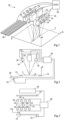
- THE figures 1, 2 and 3 represent, partially and schematically, an embodiment of an optical inspection installation 10, for example for electronic circuit boards.
- the cards to be inspected are, for example, conveyed in a direction X on a scene S, for example by conveyor belts 12, represented schematically only on the figures 2 and 3 .
- the installation 10 comprises a block 14 of camera projectors comprising two projectors 16 of images on the scene S and two groups of four cameras 18 aligned along two parallel straight lines in a direction Y, for example perpendicular to the direction X.
- the number of projectors 16 and cameras 18 and their arrangements may be different from those described in the present embodiment.
- We call Z the direction perpendicular to the directions X and Y.
- the directions figure 2 is parallel to the plane (Y, Z).
- the cameras 18 and the projectors 16 are connected to a system 20 (SYST) for controlling and using the digital images taken.
- System 20 can correspond to a dedicated electronic circuit or comprise a processor adapted to execute instructions from a computer program stored in a memory.
- the system 20 is, furthermore, adapted to control at least one motor 22, represented only in Figure 3 , driving the belts 12.
- the installation 10 comprises a support system 24, represented schematically only in figure 2 , of the block 14 projector-cameras, adapted to move the block 14 projector-camera, in particular in translation in the direction Y.
- the optical inspection installation 10 further comprises a display screen 30 connected to the control system 20.
- the control system 20 is adapted to control the display on the display screen 30 of images which are used during a calibration and/or testing process of the installation 10.
- the display screen 30 can be a liquid crystal screen, a plasma screen or a light-emitting diode screen.
- the display screen 30 is held by a support system 32, shown schematically only in figure 2 , controlled by the control system 20.
- the support device 32 is adapted to rotate the display screen 30 at least around the axis X.
- the support device 32 is , in addition, adapted to move the display screen 30 at least in the direction Z.
- the resolution of the display screen 30 is greater than or equal to 20 display pixels per centimeter, preferably greater than or equal to 30 display pixels per centimeter.
- the dimensions of the display screen are adapted to the type of calibration and/or test process to be implemented. According to one embodiment, the dimensions of the display screen 30 are sufficient so that by bringing the block 14 projector-cameras to a set of positions relative to the display screen 30, each pixel of each camera 18 sees, at least at one of these positions, at least part of the image displayed on the display screen 30.
- the dimensions of the screen 30 are such that it occupies at least 75% of the field of view of the block 14 projector-cameras, preferably more than 150% of the field of view of the block 14 projector-cameras.
- the dimensions of the display screen are greater than or equal to 380 mm by 60 mm, preferably greater than or equal to 450 mm by 100 mm.
- the display screen 30 is located outside the scene S where the objects to be inspected are transported.
- the object to be inspected is transported to the scene.
- Light patterns are projected by the projectors 16 onto the object and images of the object are acquired by the cameras 18.
- the system 20 is adapted to determine a three-dimensional image of the object arranged from images of the object acquired by the cameras 18.
- the implementation of a calibration and/or test process may include moving the camera projector block 14 until it comes directly above the display screen 30 and displaying it on the screen.
- display 30 of at least one image, preferably two images or more than two images, to carry out a calibration and/or test operation.
- the images displayed may represent calibration and/or test patterns.
- An advantage is that the same display screen 30 can be used in place of several different calibration targets.
- Another advantage is the manufacturing precision of the display screen 30 which is greater than that of conventional test patterns.
- Another advantage of using a display screen is that the displayed image is less disrupted by ambient lighting conditions than in the case of an image that would be printed on media.
- Another advantage is that the display screen 30 remains in the installation 10 so that calibration and/or test operations can be carried out on a regular basis.
- Another advantage is that the display screen 30 has a reduced cost.
- Each camera 18 may include a matrix of photodetectors distributed in rows and columns. Each photodetector is adapted to provide a detection signal representative of the quantity of light it received during an exposure period. Acquiring an image by a camera includes reading the detection signal provided by each photodetector. According to one embodiment, at least one of the cameras 18 is of the row-by-row reading type, that is to say that the detection signals are read one row of photodetectors after the other.
- the display screen 30 is controlled so that there is not one image permanently displayed but, on the contrary, an image display phase is followed by a no image display phase.
- the display and non-display phases are adapted so that the duration of exposure of each row of pixels to the same image is substantially identical.
- FIG. 4 is a block diagram of one embodiment of a calibration method.
- step 40 the system 20 controls the movement of the camera projector block 14 until it comes directly above the display screen 30.
- the system 20 can, in addition, control the support 32 to move the display screen 30 in order to bring the front face of the display screen 30 to the desired position (angle and/or level).
- step 42 the system 20 controls the movement of the camera projector block 14 until it comes directly above the display screen 30.
- the system 20 can, in addition, control the support 32 to move the display screen 30 in order to bring the front face of the display screen 30 to the desired position (angle and/or level).
- step 42 continues in step 42.
- step 42 the system 20 controls the display of at least one image, preferably at least two images, more preferably at least three successive images on the display screen and the acquisition by each camera 18 of at least one image for each image displayed.
- the process continues in step 44.
- the acquisitions may differ from each other by the image displayed and/or by the position of the camera projector block 14 and/or the display screen 30. As example, for the same image displayed, several acquisitions can be carried out, the position of the projector-camera block 14 being different between acquisitions of the same image and/or the position of the display screen 30 being different between acquisitions .
- a series can be displayed of several images at a first position of the block 14 projector-cameras and the display screen 30, then the same series of images or another series of images at a second position of the block 14 projector-cameras and the screen 30.
- step 44 the system 20 carries out the desired calibration and/or test operation based on processing of the acquired images. The process continues in step 46.
- step 46 the system 20 controls the movement of the camera projector block 14 and/or the movement of the display screen 30 to a normal operating position of the optical inspection installation 10. Step 46 can be carried out at least in part simultaneously with step 44.
- the images displayed on the display screen 30 and acquired by the cameras 18 in step 42 are adapted to carrying out a geometric calibration of the cameras 18 in step 44.
- An operation of The geometric calibration may include the estimation, for each camera 18, of the parameter values of an equivalent mathematical model of the camera 18 which makes each point of the scene S correspond to a corresponding point in the plane of the photodetectors of the camera 18
- the mathematical model is used during normal operation of the optical inspection installation 10.
- the parameters may include intrinsic parameters such as the main point, the focal length of the camera 18 according to different axes, the inclination parameter (in English "skew") of the camera 18 and extrinsic parameters such as the translation matrix and the rotation matrix of the geometric transformation between a fixed reference coordinate system with respect to the block 14 projector-cameras and a coordinate system linked to the camera 18.
- a geometric calibration operation can include the determination, for each camera 18, of a correspondence table which corresponds to a set of points of the scene S of the points of the image acquired by the camera 18.
- the image displayed on the display screen 30 may include patterns allowing the determination of precise reference points of the displayed image whose positions relative to the coordinate system of reference are known.
- each pattern corresponds to a black dot on a white background, a cross or a square.
- the associated reference point may correspond to the point of intersection of the cross and when the pattern corresponds to a square, the associated reference point may correspond to the center of the square.
- the geometric calibration operation of a camera 18 may include a step in which, for each reference point of the displayed image, the corresponding point in the image acquired by the camera 18 is determined.
- the displayed image includes a large number of reference points, it can be difficult to simply match the reference points of the displayed image to the corresponding points of the acquired image.
- a unique pattern is generally provided that is easily identifiable on the acquired image. The identification of the reference points is then carried out by comparing their respective positions in relation to the unique pattern, which can be a delicate operation.
- the geometric calibration method comprises the display of several successive images and for each image displayed, the acquisition of an image by each camera 18.
- Each image displayed comprises, in addition, for each point of reference, the display of one or the other of a first pattern or a second pattern.
- FIG. 5 represents an embodiment of an image I displayed on the display screen 30 and which comprises white squares 48 with black edges and black squares 50.
- a reference point corresponds to the center of each square 48 or 50.
- the first pattern for example the white square 48
- the second pattern for example the black square 50
- the display of several successive images on the display screen 30 with, for each reference point, the display of a white or black square allows the transmission of a digital signal for each reference point comprising a succession logical values “1” and “0”.
- the digital signal may correspond to a code which makes it possible to identify the reference point on the displayed image.
- the analysis of the images acquired by each camera 18 allows the determination of the digital signal for each reference point on the acquired images.
- An advantage of such a method is that it makes it possible to directly identify each reference point without requiring the determination of the relative position of the reference point with respect to a unique pattern. The reliability of the method for determining the reference points is then increased.
- the displayed image is a pseudo-random image determined so that, whatever the reference point of the displayed image and part of the image selected in a window around the reference point, no two parts of the image are the same.
- the system 20 is adapted to determine the pixel of the acquired image corresponding to each reference point of the displayed image by searching for the pixel of the associated acquired image with the same part of the image as the reference point of the displayed image while taking into account the deformations of the acquired image in relation to the displayed image due to the inclination of the camera.
- the images displayed on the display screen 30 in step 42 and acquired by the cameras 18 are adapted to produce an estimate of the sharpness of each camera 18.
- the method comprises displaying on the display screen 30 at least one image comprising alternating black lines and white lines. Processing of images acquired by each camera 18 can correspond to a classic method of estimating the sharpness of each camera 18 using a physical target of the same appearance. According to one embodiment, several images are displayed successively by modifying the orientation of the lines displayed from one image to another. This advantageously allows the sharpness of each camera 18 to be estimated in different directions.
- each display pixel of the display screen comprises an active zone from which the majority of the radiation provided by the display pixel is emitted and an inactive zone which does not emit substantially no radiation.
- the inactive areas of the display pixels of the same row or the same column are aligned. This makes it possible to take into account the lines formed by the inactive areas of the display pixels in the displayed image for the estimation of the sharpness of the camera and to increase the resolution of the displayed image in relation to the resolution of the display screen 30.
- the images displayed on the display screen 30 in step 42 and acquired by the cameras 18 are adapted to carrying out a diagnosis of the cameras 18 in step 44.
- a diagnosis may include the characterization of defects in each camera 18.
- An example of a defect corresponds to the presence of photodetectors of the camera 18 which no longer function and which result in black pixels on the acquired images.
- Another example of defect corresponds to differences between the amplification gains of the photodetectors, from which it results that the image acquired from a uniformly gray image displayed on the display screen 30 may not be uniformly grey.
- the display screen 30 allows the display of several images to characterize the defects of each camera 30.
- the images displayed on the display screen 30 in step 42 and acquired by the cameras 18 are suitable for carrying out a radiometric calibration of each camera 18 in step 44. It may be advantageous, in this case, to provide regular calibration of the display screen, for example by using a calibration probe.
- the images displayed on the display screen 30 in step 42 and acquired by the cameras 18 are suitable for carrying out tests of the method of processing the images acquired by the cameras 18 implemented by the system 20 in normal operation.
- An example of a classic test includes the acquisition of images by the cameras 18 of a known real electronic card dedicated to the test.
- a disadvantage is that the structure of the electronic test card cannot be known perfectly. Additionally, different electronic test boards must be used depending on the aspects of the processing process to be tested. The number of electronic test cards available is nevertheless necessarily limited.
- the image displayed by the display screen 30 may correspond to the computer-designed image of an electronic test card. Compared to a test which includes the acquisition of images of a real electronic card, the display of images of a computer-designed dummy electronic card advantageously makes it possible to display images which are perfectly known and which can be easily modified according to the tests to be carried out.
- FIG. 6 represents, in a partial and schematic manner, another embodiment of an optical inspection installation 55.
- the optical inspection installation 55 comprises all of the elements of the optical inspection installation 10 represented in figure 1 with the difference that the display screen 30 is replaced by a display screen 56 which extends under the entire scene.
- the dimensions of the images displayed by the display screen 56 can be 60 cm by 60 cm.
- the large dimensions of the images displayed by the display screen 56 allow part of the displayed image to always be in the field of vision of the cameras 18 regardless of the position of the projector-camera block 14 relative to the scene S.
- the images displayed on the display screen 56 are adapted to test whether the method of controlling the movements of the projector-camera block 14 is working correctly.
- the displayed image may include patterns, each pattern allowing the identification of precise reference points of the displayed image.
- an optical installation may comprise the display screen 30 described previously in relation to the figures 1 to 3 and the display screen 56 described previously in relation to the Figure 6 , the display screens 30, 56 being used for different calibration operations.
Landscapes
- Engineering & Computer Science (AREA)
- Multimedia (AREA)
- Signal Processing (AREA)
- Physics & Mathematics (AREA)
- Health & Medical Sciences (AREA)
- Life Sciences & Earth Sciences (AREA)
- Chemical & Material Sciences (AREA)
- Analytical Chemistry (AREA)
- Biochemistry (AREA)
- General Health & Medical Sciences (AREA)
- General Physics & Mathematics (AREA)
- Immunology (AREA)
- Pathology (AREA)
- Length Measuring Devices By Optical Means (AREA)
- Testing, Inspecting, Measuring Of Stereoscopic Televisions And Televisions (AREA)
Claims (12)
- Anlage (10; 55) für die optische Inspektion eines Objekts, die Folgendes aufweist:mindestens eine Kamera (18);einen Bildschirm (30; 56) zur Anzeige mehrerer aufeinanderfolgender Bilder, wobei jedes angezeigte Bild an jedem Bezugspunkt des angezeigten Bildes unter den Bezugspunkten die Anzeige eines oder eines anderen Musters aus einem ersten Musters oder einem zweiten Musters aufweist;ein System (24, 32) zum Versetzen des Anzeigebildschirms und/oder der Kamera, um den Anzeigebildschirm in das Sichtfeld der Kamera zu bringen;ein System (20) zum Steuern des Anzeigebildschirms und der Kamera, um durch die Kamera mindestens ein Bild für jedes auf dem Anzeigebildschirm angezeigte Bild zu erfassen, wobei das Steuersystem dazu bestimmt ist, die erfassten Bilder für einen Kalibrierungsvorgang des optischen Inspektionssystems zu verarbeiten, was die Bestimmung eines digitalen Signals für jeden Bezugspunkt aufweisend eine Folge von logischen Werten "1" und "0" aufweist, die einem Identifikationscode für den Bezugspunkt entsprechen.
- Optische Inspektionsanlage nach Anspruch 1, die ferner ein System (12, 22) zum Überführen des Objekts aufweist.
- Anlage nach Anspruch 1 oder 2, wobei das zu inspizierende Objekt eine elektronische Karte ist.
- Optische Inspektionsanlage nach einem der Ansprüche 1 bis 3, wobei das Steuerungssystem (20) dazu ausgebildet ist, aus den von der Kamera aufgenommenen Bildern ein dreidimensionales Bild des Objekts zu ermitteln.
- Optische Inspektionsanlage nach einem der Ansprüche 1 bis 4, ferner aufweisend mindestens einen Projektor (14) für Leuchtmuster auf dem Objekt.
- Optische Inspektionsanlage nach einem der Ansprüche 1 bis 5, aufweisend ein Fahrgestell, wobei der das Versatzsystem eine Vorrichtung zum Versetzen der Kamera (18) relativ zum Fahrgestell aufweist.
- Optische Inspektionsanlage nach Anspruch 6, wobei das Versatzsystem eine Vorrichtung zum Versetzen und/oder Kippen des Bildschirms (30) relativ zum Fahrgestell aufweist.
- Verfahren zur Steuerung einer Anlage (10; 55) für die optische Inspektion eines Objekts, wobei die Anlage mindestens eine Kamera (18) und einen Bildschirm (30; 56) aufweist, wobei das Verfahren die folgenden Schritte aufweist:Versetzen des Bildschirms und/oder der Kamera, um den Bildschirm in das Sichtfeld der Kamera zu bringen;Anzeigen mehrerer aufeinanderfolgender Bilder (I) auf dem Bildschirm, wobei jedes Bild an jedem Bezugspunkt des angezeigten Bildes unter den Bezugspunkten die Anzeige eines oder eines anderen Musters aus einem ersten Musters oder einem zweiten Musters aufweist,für jedes angezeigte Bild, Erfassen mindestens eines Bildes von der Kamera; undVerarbeiten der für einen Kalibrierungsvorgang der optischen Inspektionsanlage erfassten Bilder, aufweisend die Bestimmung eines digitalen Signals für jeden Bezugspunkt, was eine Folge von logischen Werten "1" und "0" aufweist, die einem Identifikationscode des Bezugspunkts entsprechen.
- Verfahren nach Anspruch 8, wobei der Vorgang die geometrische Kalibrierung der Kamera (18) ist.
- Verfahren nach Anspruch 8, wobei das angezeigte Bild das Bild einer elektronischen Karte ist.
- Verfahren nach Anspruch 8, wobei der Vorgang die radiometrische Kalibrierung der Kamera (18) ist.
- Verfahren nach einem der Ansprüche 8 bis 11, wobei die optische Inspektionsanlage (10; 55) ein Fahrgestell aufweist und wobei das Verfahren außerdem das Versetzen und/oder Kippen des Bildschirms (30) relativ zum Fahrgestell aufweist.
Applications Claiming Priority (2)
| Application Number | Priority Date | Filing Date | Title |
|---|---|---|---|
| FR1558603A FR3041111B1 (fr) | 2015-09-15 | 2015-09-15 | Mire d'etalonnage ou de test |
| PCT/FR2016/052199 WO2017046475A1 (fr) | 2015-09-15 | 2016-09-05 | Mire d'etalonnage ou de test |
Publications (2)
| Publication Number | Publication Date |
|---|---|
| EP3350581A1 EP3350581A1 (de) | 2018-07-25 |
| EP3350581B1 true EP3350581B1 (de) | 2023-11-08 |
Family
ID=54366421
Family Applications (1)
| Application Number | Title | Priority Date | Filing Date |
|---|---|---|---|
| EP16775781.4A Active EP3350581B1 (de) | 2015-09-15 | 2016-09-05 | Kalibrier- oder testmuster |
Country Status (3)
| Country | Link |
|---|---|
| EP (1) | EP3350581B1 (de) |
| FR (1) | FR3041111B1 (de) |
| WO (1) | WO2017046475A1 (de) |
Families Citing this family (1)
| Publication number | Priority date | Publication date | Assignee | Title |
|---|---|---|---|---|
| CN115854918A (zh) * | 2023-02-17 | 2023-03-28 | 天津中安视通科技有限公司 | 一种辅助检验大口径视窗组件面型的方法 |
Family Cites Families (5)
| Publication number | Priority date | Publication date | Assignee | Title |
|---|---|---|---|---|
| US7373270B2 (en) * | 2003-03-26 | 2008-05-13 | Sony Corporation | Diagnosing device for stereo camera mounted on robot, and diagnostic method of stereo camera mounted on robot apparatus |
| US8542267B1 (en) * | 2009-10-01 | 2013-09-24 | Hewlett-Packard Development Company, L.P. | Calibrating a visual-collaborative system |
| DE102013014475B4 (de) * | 2012-08-29 | 2020-11-12 | Technische Universität Ilmenau | Verfahren zur Erkennung und Kompensation von Messabweichungen während des Betriebes einer optischen Messvorrichtung, optisches Messverfahren und optische Messvorrichtung |
| FR3004582B1 (fr) * | 2013-04-11 | 2015-04-10 | Vit | Systeme et procede d'inspection optique de circuits electroniques |
| US20150103147A1 (en) * | 2013-10-14 | 2015-04-16 | Etron Technology, Inc. | Image calibration system and calibration method of a stereo camera |
-
2015
- 2015-09-15 FR FR1558603A patent/FR3041111B1/fr not_active Expired - Fee Related
-
2016
- 2016-09-05 WO PCT/FR2016/052199 patent/WO2017046475A1/fr not_active Ceased
- 2016-09-05 EP EP16775781.4A patent/EP3350581B1/de active Active
Also Published As
| Publication number | Publication date |
|---|---|
| WO2017046475A1 (fr) | 2017-03-23 |
| EP3350581A1 (de) | 2018-07-25 |
| FR3041111B1 (fr) | 2017-09-15 |
| FR3041111A1 (fr) | 2017-03-17 |
Similar Documents
| Publication | Publication Date | Title |
|---|---|---|
| EP1462992B1 (de) | Anordnung und Verfahren zur Gestaltrekonstruktion aus optischen Bildern | |
| US7019826B2 (en) | Optical inspection system, apparatus and method for reconstructing three-dimensional images for printed circuit board and electronics manufacturing inspection | |
| US7171037B2 (en) | Optical inspection system and method for displaying imaged objects in greater than two dimensions | |
| US20040184653A1 (en) | Optical inspection system, illumination apparatus and method for use in imaging specular objects based on illumination gradients | |
| BE1022486B1 (fr) | Un systeme d'appareil de prise de vues tof et une methode pour mesurer une distance avec le systeme | |
| WO2015071457A1 (fr) | Procede d'estimation de la vitesse de deplacement d'une camera | |
| WO2009077534A1 (fr) | Dispositif d'evaluation de la surface d'un pneumatique | |
| US10270947B2 (en) | Flat digital image sensor | |
| EP3072109A1 (de) | Verfahren zur schätzung der geschwindigkeit der verschiebung einer kamera | |
| EP2984443B1 (de) | Dreidimensionales bilderfassungssystem | |
| EP3350581B1 (de) | Kalibrier- oder testmuster | |
| FR2950138A1 (fr) | Procede de numerisation tridimensionnelle a recalage rapide | |
| WO2012035257A1 (fr) | Dispositif et procédé de mesure de la forme d'un miroir ou d'une surface speculaire | |
| FR3054914A1 (fr) | Procede d'inspection optique d'un objet | |
| FR3034233A1 (fr) | Procede de correction d'une image d'au moins un objet presente a distance devant un imageur et eclaire par un systeme d'eclairage et systeme de prise de vues pour la mise en œuvre dudit procede | |
| WO2020229780A1 (fr) | Procédé et système d'inspection optique d'un objet | |
| FR2980863A1 (fr) | Banc de detection de defauts d'ecrans lcd | |
| EP2951526A1 (de) | System zur bestimmung eines dreidimensionalen bildes einer elektrischen schaltung | |
| WO2019224436A1 (fr) | Systeme de determination d'images tridimensionnelles | |
| FR3052287B1 (fr) | Construction d'une image tridimensionnelle | |
| WO2018229358A1 (fr) | Procédé et dispositif de construction d'une image tridimensionnelle | |
| EP3475676A1 (de) | Kalibrierungsmuster für ein bildgebungssystem | |
| WO2023105164A1 (fr) | Procédé et dispositif de caractérisation de distorsions dans une caméra plénoptique |
Legal Events
| Date | Code | Title | Description |
|---|---|---|---|
| STAA | Information on the status of an ep patent application or granted ep patent |
Free format text: STATUS: THE INTERNATIONAL PUBLICATION HAS BEEN MADE |
|
| PUAI | Public reference made under article 153(3) epc to a published international application that has entered the european phase |
Free format text: ORIGINAL CODE: 0009012 |
|
| STAA | Information on the status of an ep patent application or granted ep patent |
Free format text: STATUS: REQUEST FOR EXAMINATION WAS MADE |
|
| 17P | Request for examination filed |
Effective date: 20180223 |
|
| AK | Designated contracting states |
Kind code of ref document: A1 Designated state(s): AL AT BE BG CH CY CZ DE DK EE ES FI FR GB GR HR HU IE IS IT LI LT LU LV MC MK MT NL NO PL PT RO RS SE SI SK SM TR |
|
| AX | Request for extension of the european patent |
Extension state: BA ME |
|
| DAV | Request for validation of the european patent (deleted) | ||
| DAX | Request for extension of the european patent (deleted) | ||
| RIC1 | Information provided on ipc code assigned before grant |
Ipc: G06T 7/00 20170101ALI20170403BHEP Ipc: H05K 13/08 20060101ALI20170403BHEP Ipc: G01N 21/93 20060101AFI20170403BHEP Ipc: G01N 21/956 20060101ALI20170403BHEP Ipc: H04N 13/02 20060101ALI20170403BHEP |
|
| STAA | Information on the status of an ep patent application or granted ep patent |
Free format text: STATUS: EXAMINATION IS IN PROGRESS |
|
| 17Q | First examination report despatched |
Effective date: 20210531 |
|
| RIC1 | Information provided on ipc code assigned before grant |
Ipc: H04N 23/90 20230101ALI20230329BHEP Ipc: H04N 23/63 20230101ALI20230329BHEP Ipc: G01N 21/956 20060101ALI20230329BHEP Ipc: H05K 13/08 20060101ALI20230329BHEP Ipc: G06T 7/00 20170101ALI20230329BHEP Ipc: G01N 21/93 20060101AFI20230329BHEP |
|
| GRAP | Despatch of communication of intention to grant a patent |
Free format text: ORIGINAL CODE: EPIDOSNIGR1 |
|
| STAA | Information on the status of an ep patent application or granted ep patent |
Free format text: STATUS: GRANT OF PATENT IS INTENDED |
|
| INTG | Intention to grant announced |
Effective date: 20230508 |
|
| GRAS | Grant fee paid |
Free format text: ORIGINAL CODE: EPIDOSNIGR3 |
|
| GRAA | (expected) grant |
Free format text: ORIGINAL CODE: 0009210 |
|
| STAA | Information on the status of an ep patent application or granted ep patent |
Free format text: STATUS: THE PATENT HAS BEEN GRANTED |
|
| AK | Designated contracting states |
Kind code of ref document: B1 Designated state(s): AL AT BE BG CH CY CZ DE DK EE ES FI FR GB GR HR HU IE IS IT LI LT LU LV MC MK MT NL NO PL PT RO RS SE SI SK SM TR |
|
| REG | Reference to a national code |
Ref country code: GB Ref legal event code: FG4D Free format text: NOT ENGLISH |
|
| REG | Reference to a national code |
Ref country code: CH Ref legal event code: EP |
|
| REG | Reference to a national code |
Ref country code: DE Ref legal event code: R096 Ref document number: 602016084016 Country of ref document: DE |
|
| REG | Reference to a national code |
Ref country code: IE Ref legal event code: FG4D Free format text: LANGUAGE OF EP DOCUMENT: FRENCH |
|
| REG | Reference to a national code |
Ref country code: LT Ref legal event code: MG9D |
|
| REG | Reference to a national code |
Ref country code: NL Ref legal event code: MP Effective date: 20231108 |
|
| PG25 | Lapsed in a contracting state [announced via postgrant information from national office to epo] |
Ref country code: GR Free format text: LAPSE BECAUSE OF FAILURE TO SUBMIT A TRANSLATION OF THE DESCRIPTION OR TO PAY THE FEE WITHIN THE PRESCRIBED TIME-LIMIT Effective date: 20240209 |
|
| PG25 | Lapsed in a contracting state [announced via postgrant information from national office to epo] |
Ref country code: IS Free format text: LAPSE BECAUSE OF FAILURE TO SUBMIT A TRANSLATION OF THE DESCRIPTION OR TO PAY THE FEE WITHIN THE PRESCRIBED TIME-LIMIT Effective date: 20240308 |
|
| PG25 | Lapsed in a contracting state [announced via postgrant information from national office to epo] |
Ref country code: LT Free format text: LAPSE BECAUSE OF FAILURE TO SUBMIT A TRANSLATION OF THE DESCRIPTION OR TO PAY THE FEE WITHIN THE PRESCRIBED TIME-LIMIT Effective date: 20231108 |
|
| REG | Reference to a national code |
Ref country code: AT Ref legal event code: MK05 Ref document number: 1630013 Country of ref document: AT Kind code of ref document: T Effective date: 20231108 |
|
| PG25 | Lapsed in a contracting state [announced via postgrant information from national office to epo] |
Ref country code: NL Free format text: LAPSE BECAUSE OF FAILURE TO SUBMIT A TRANSLATION OF THE DESCRIPTION OR TO PAY THE FEE WITHIN THE PRESCRIBED TIME-LIMIT Effective date: 20231108 |
|
| PG25 | Lapsed in a contracting state [announced via postgrant information from national office to epo] |
Ref country code: AT Free format text: LAPSE BECAUSE OF FAILURE TO SUBMIT A TRANSLATION OF THE DESCRIPTION OR TO PAY THE FEE WITHIN THE PRESCRIBED TIME-LIMIT Effective date: 20231108 |
|
| PG25 | Lapsed in a contracting state [announced via postgrant information from national office to epo] |
Ref country code: ES Free format text: LAPSE BECAUSE OF FAILURE TO SUBMIT A TRANSLATION OF THE DESCRIPTION OR TO PAY THE FEE WITHIN THE PRESCRIBED TIME-LIMIT Effective date: 20231108 |
|
| PG25 | Lapsed in a contracting state [announced via postgrant information from national office to epo] |
Ref country code: NL Free format text: LAPSE BECAUSE OF FAILURE TO SUBMIT A TRANSLATION OF THE DESCRIPTION OR TO PAY THE FEE WITHIN THE PRESCRIBED TIME-LIMIT Effective date: 20231108 Ref country code: LT Free format text: LAPSE BECAUSE OF FAILURE TO SUBMIT A TRANSLATION OF THE DESCRIPTION OR TO PAY THE FEE WITHIN THE PRESCRIBED TIME-LIMIT Effective date: 20231108 Ref country code: IS Free format text: LAPSE BECAUSE OF FAILURE TO SUBMIT A TRANSLATION OF THE DESCRIPTION OR TO PAY THE FEE WITHIN THE PRESCRIBED TIME-LIMIT Effective date: 20240308 Ref country code: GR Free format text: LAPSE BECAUSE OF FAILURE TO SUBMIT A TRANSLATION OF THE DESCRIPTION OR TO PAY THE FEE WITHIN THE PRESCRIBED TIME-LIMIT Effective date: 20240209 Ref country code: ES Free format text: LAPSE BECAUSE OF FAILURE TO SUBMIT A TRANSLATION OF THE DESCRIPTION OR TO PAY THE FEE WITHIN THE PRESCRIBED TIME-LIMIT Effective date: 20231108 Ref country code: BG Free format text: LAPSE BECAUSE OF FAILURE TO SUBMIT A TRANSLATION OF THE DESCRIPTION OR TO PAY THE FEE WITHIN THE PRESCRIBED TIME-LIMIT Effective date: 20240208 Ref country code: AT Free format text: LAPSE BECAUSE OF FAILURE TO SUBMIT A TRANSLATION OF THE DESCRIPTION OR TO PAY THE FEE WITHIN THE PRESCRIBED TIME-LIMIT Effective date: 20231108 Ref country code: PT Free format text: LAPSE BECAUSE OF FAILURE TO SUBMIT A TRANSLATION OF THE DESCRIPTION OR TO PAY THE FEE WITHIN THE PRESCRIBED TIME-LIMIT Effective date: 20240308 |
|
| PG25 | Lapsed in a contracting state [announced via postgrant information from national office to epo] |
Ref country code: SE Free format text: LAPSE BECAUSE OF FAILURE TO SUBMIT A TRANSLATION OF THE DESCRIPTION OR TO PAY THE FEE WITHIN THE PRESCRIBED TIME-LIMIT Effective date: 20231108 Ref country code: RS Free format text: LAPSE BECAUSE OF FAILURE TO SUBMIT A TRANSLATION OF THE DESCRIPTION OR TO PAY THE FEE WITHIN THE PRESCRIBED TIME-LIMIT Effective date: 20231108 Ref country code: PL Free format text: LAPSE BECAUSE OF FAILURE TO SUBMIT A TRANSLATION OF THE DESCRIPTION OR TO PAY THE FEE WITHIN THE PRESCRIBED TIME-LIMIT Effective date: 20231108 Ref country code: NO Free format text: LAPSE BECAUSE OF FAILURE TO SUBMIT A TRANSLATION OF THE DESCRIPTION OR TO PAY THE FEE WITHIN THE PRESCRIBED TIME-LIMIT Effective date: 20240208 Ref country code: LV Free format text: LAPSE BECAUSE OF FAILURE TO SUBMIT A TRANSLATION OF THE DESCRIPTION OR TO PAY THE FEE WITHIN THE PRESCRIBED TIME-LIMIT Effective date: 20231108 Ref country code: HR Free format text: LAPSE BECAUSE OF FAILURE TO SUBMIT A TRANSLATION OF THE DESCRIPTION OR TO PAY THE FEE WITHIN THE PRESCRIBED TIME-LIMIT Effective date: 20231108 |
|
| PG25 | Lapsed in a contracting state [announced via postgrant information from national office to epo] |
Ref country code: DK Free format text: LAPSE BECAUSE OF FAILURE TO SUBMIT A TRANSLATION OF THE DESCRIPTION OR TO PAY THE FEE WITHIN THE PRESCRIBED TIME-LIMIT Effective date: 20231108 |
|
| PG25 | Lapsed in a contracting state [announced via postgrant information from national office to epo] |
Ref country code: CZ Free format text: LAPSE BECAUSE OF FAILURE TO SUBMIT A TRANSLATION OF THE DESCRIPTION OR TO PAY THE FEE WITHIN THE PRESCRIBED TIME-LIMIT Effective date: 20231108 |
|
| PG25 | Lapsed in a contracting state [announced via postgrant information from national office to epo] |
Ref country code: SK Free format text: LAPSE BECAUSE OF FAILURE TO SUBMIT A TRANSLATION OF THE DESCRIPTION OR TO PAY THE FEE WITHIN THE PRESCRIBED TIME-LIMIT Effective date: 20231108 |
|
| PG25 | Lapsed in a contracting state [announced via postgrant information from national office to epo] |
Ref country code: SM Free format text: LAPSE BECAUSE OF FAILURE TO SUBMIT A TRANSLATION OF THE DESCRIPTION OR TO PAY THE FEE WITHIN THE PRESCRIBED TIME-LIMIT Effective date: 20231108 Ref country code: SK Free format text: LAPSE BECAUSE OF FAILURE TO SUBMIT A TRANSLATION OF THE DESCRIPTION OR TO PAY THE FEE WITHIN THE PRESCRIBED TIME-LIMIT Effective date: 20231108 Ref country code: RO Free format text: LAPSE BECAUSE OF FAILURE TO SUBMIT A TRANSLATION OF THE DESCRIPTION OR TO PAY THE FEE WITHIN THE PRESCRIBED TIME-LIMIT Effective date: 20231108 Ref country code: IT Free format text: LAPSE BECAUSE OF FAILURE TO SUBMIT A TRANSLATION OF THE DESCRIPTION OR TO PAY THE FEE WITHIN THE PRESCRIBED TIME-LIMIT Effective date: 20231108 Ref country code: EE Free format text: LAPSE BECAUSE OF FAILURE TO SUBMIT A TRANSLATION OF THE DESCRIPTION OR TO PAY THE FEE WITHIN THE PRESCRIBED TIME-LIMIT Effective date: 20231108 Ref country code: DK Free format text: LAPSE BECAUSE OF FAILURE TO SUBMIT A TRANSLATION OF THE DESCRIPTION OR TO PAY THE FEE WITHIN THE PRESCRIBED TIME-LIMIT Effective date: 20231108 Ref country code: CZ Free format text: LAPSE BECAUSE OF FAILURE TO SUBMIT A TRANSLATION OF THE DESCRIPTION OR TO PAY THE FEE WITHIN THE PRESCRIBED TIME-LIMIT Effective date: 20231108 |
|
| REG | Reference to a national code |
Ref country code: DE Ref legal event code: R097 Ref document number: 602016084016 Country of ref document: DE |
|
| PLBE | No opposition filed within time limit |
Free format text: ORIGINAL CODE: 0009261 |
|
| STAA | Information on the status of an ep patent application or granted ep patent |
Free format text: STATUS: NO OPPOSITION FILED WITHIN TIME LIMIT |
|
| 26N | No opposition filed |
Effective date: 20240809 |
|
| PG25 | Lapsed in a contracting state [announced via postgrant information from national office to epo] |
Ref country code: SI Free format text: LAPSE BECAUSE OF FAILURE TO SUBMIT A TRANSLATION OF THE DESCRIPTION OR TO PAY THE FEE WITHIN THE PRESCRIBED TIME-LIMIT Effective date: 20231108 |
|
| PG25 | Lapsed in a contracting state [announced via postgrant information from national office to epo] |
Ref country code: SI Free format text: LAPSE BECAUSE OF FAILURE TO SUBMIT A TRANSLATION OF THE DESCRIPTION OR TO PAY THE FEE WITHIN THE PRESCRIBED TIME-LIMIT Effective date: 20231108 |
|
| REG | Reference to a national code |
Ref country code: DE Ref legal event code: R119 Ref document number: 602016084016 Country of ref document: DE |
|
| PG25 | Lapsed in a contracting state [announced via postgrant information from national office to epo] |
Ref country code: MC Free format text: LAPSE BECAUSE OF FAILURE TO SUBMIT A TRANSLATION OF THE DESCRIPTION OR TO PAY THE FEE WITHIN THE PRESCRIBED TIME-LIMIT Effective date: 20231108 |
|
| REG | Reference to a national code |
Ref country code: CH Ref legal event code: PL |
|
| PG25 | Lapsed in a contracting state [announced via postgrant information from national office to epo] |
Ref country code: LU Free format text: LAPSE BECAUSE OF NON-PAYMENT OF DUE FEES Effective date: 20240905 |
|
| GBPC | Gb: european patent ceased through non-payment of renewal fee |
Effective date: 20240905 |
|
| PG25 | Lapsed in a contracting state [announced via postgrant information from national office to epo] |
Ref country code: DE Free format text: LAPSE BECAUSE OF NON-PAYMENT OF DUE FEES Effective date: 20250401 |
|
| PG25 | Lapsed in a contracting state [announced via postgrant information from national office to epo] |
Ref country code: GB Free format text: LAPSE BECAUSE OF NON-PAYMENT OF DUE FEES Effective date: 20240905 |
|
| REG | Reference to a national code |
Ref country code: BE Ref legal event code: MM Effective date: 20240930 |
|
| PG25 | Lapsed in a contracting state [announced via postgrant information from national office to epo] |
Ref country code: BE Free format text: LAPSE BECAUSE OF NON-PAYMENT OF DUE FEES Effective date: 20240930 |
|
| PG25 | Lapsed in a contracting state [announced via postgrant information from national office to epo] |
Ref country code: CH Free format text: LAPSE BECAUSE OF NON-PAYMENT OF DUE FEES Effective date: 20240930 |
|
| PG25 | Lapsed in a contracting state [announced via postgrant information from national office to epo] |
Ref country code: IE Free format text: LAPSE BECAUSE OF NON-PAYMENT OF DUE FEES Effective date: 20240905 |
|
| PG25 | Lapsed in a contracting state [announced via postgrant information from national office to epo] |
Ref country code: FI Free format text: LAPSE BECAUSE OF FAILURE TO SUBMIT A TRANSLATION OF THE DESCRIPTION OR TO PAY THE FEE WITHIN THE PRESCRIBED TIME-LIMIT Effective date: 20231108 |
|
| PGFP | Annual fee paid to national office [announced via postgrant information from national office to epo] |
Ref country code: FR Payment date: 20250930 Year of fee payment: 10 |
|
| PG25 | Lapsed in a contracting state [announced via postgrant information from national office to epo] |
Ref country code: CY Free format text: LAPSE BECAUSE OF FAILURE TO SUBMIT A TRANSLATION OF THE DESCRIPTION OR TO PAY THE FEE WITHIN THE PRESCRIBED TIME-LIMIT; INVALID AB INITIO Effective date: 20160905 |