EP3350571B1 - Vorrichtung auf basis eines helmholz-resonators zur detektion von gasen mit höher empfindlichkeit - Google Patents
Vorrichtung auf basis eines helmholz-resonators zur detektion von gasen mit höher empfindlichkeit Download PDFInfo
- Publication number
- EP3350571B1 EP3350571B1 EP16806222.2A EP16806222A EP3350571B1 EP 3350571 B1 EP3350571 B1 EP 3350571B1 EP 16806222 A EP16806222 A EP 16806222A EP 3350571 B1 EP3350571 B1 EP 3350571B1
- Authority
- EP
- European Patent Office
- Prior art keywords
- tubes
- gas
- primary
- tank
- radiant
- Prior art date
- Legal status (The legal status is an assumption and is not a legal conclusion. Google has not performed a legal analysis and makes no representation as to the accuracy of the status listed.)
- Active
Links
Images

Classifications
-
- G—PHYSICS
- G01—MEASURING; TESTING
- G01N—INVESTIGATING OR ANALYSING MATERIALS BY DETERMINING THEIR CHEMICAL OR PHYSICAL PROPERTIES
- G01N21/00—Investigating or analysing materials by the use of optical means, i.e. using sub-millimetre waves, infrared, visible or ultraviolet light
- G01N21/17—Systems in which incident light is modified in accordance with the properties of the material investigated
- G01N21/1702—Systems in which incident light is modified in accordance with the properties of the material investigated with opto-acoustic detection, e.g. for gases or analysing solids
-
- G—PHYSICS
- G01—MEASURING; TESTING
- G01N—INVESTIGATING OR ANALYSING MATERIALS BY DETERMINING THEIR CHEMICAL OR PHYSICAL PROPERTIES
- G01N21/00—Investigating or analysing materials by the use of optical means, i.e. using sub-millimetre waves, infrared, visible or ultraviolet light
- G01N21/01—Arrangements or apparatus for facilitating the optical investigation
- G01N21/03—Cuvette constructions
- G01N21/05—Flow-through cuvettes
-
- G—PHYSICS
- G01—MEASURING; TESTING
- G01N—INVESTIGATING OR ANALYSING MATERIALS BY DETERMINING THEIR CHEMICAL OR PHYSICAL PROPERTIES
- G01N21/00—Investigating or analysing materials by the use of optical means, i.e. using sub-millimetre waves, infrared, visible or ultraviolet light
- G01N21/17—Systems in which incident light is modified in accordance with the properties of the material investigated
- G01N21/1702—Systems in which incident light is modified in accordance with the properties of the material investigated with opto-acoustic detection, e.g. for gases or analysing solids
- G01N2021/1704—Systems in which incident light is modified in accordance with the properties of the material investigated with opto-acoustic detection, e.g. for gases or analysing solids in gases
Definitions
- the present invention aims at a very high sensitivity gas analysis device based on a Helmholtz resonator. It applies, in particular, to the detection of traces of gas in the ambient air, for example for the fight against pollution, the detection of gas leaks or the prevention of chemical risks.
- CRDS technology (acronym for Cavity Ring-Down Spectroscopy for cavity decay time spectroscopy), OFCEAS technology (acronym for Optical Feedback Cavity Enhanced Absorption Spectroscopy for enhanced absorption spectroscopy in cavity by optical return) and photo-acoustic technology.
- Photo-acoustic technology is particularly interesting due to its simplicity, its robustness and the limit detection levels that can be achieved while maintaining a high level of selectivity. Industrial needs to date are no longer at the ppb level but are tending towards ppt (parts per trillion, or 10 -12 ).
- Photo-acoustic technology makes it possible to achieve the same limit detection levels as other techniques with the advantages of simplicity of adjustment and stability over time coupled with rapid measurement. However, it also does not offer the levels of detection now required in industrial applications.
- a Helmholtz cell gas detection device is described in the patent FR 2 815 122 .
- This device consists of a laser whose beam, modulated at the resonance frequency of the cell, passes through a measuring cell.
- the cell is made up of two large volumes connected by two capillaries.
- the cell is closed by four semi-transparent windows to let the laser beam pass through.
- the Helmholtz resonance makes it possible to carry out a differential measurement in which the signals from the two acousto-electric transducers, for example, microphones, are in phase opposition. The measurement of the difference in the voltages of the signals leaving the transducers is then proportional to the concentration of the gas in the cell.
- the first transducer allows the measurement of pressure variations in the first large volume.
- the second transducer measures the pressure in the second volume, in phase opposition to the first volume.
- a differential measurement makes it possible to double the photo-acoustic signal due to the presence of gas in the cell while simultaneously subtracting the surrounding parasitic noise.
- One of the conditions which leads to the creation of the stationary pressure wave is imposed by the maximized overlap between the modulation of the light intensity emitted by the laser and the distribution of the resonance mode considered.
- the operating frequency of all the elements constituting the photo-acoustic system is imposed by the acoustic resonance frequency of the measuring cell.
- the frequency of a Helmholtz resonator with macroscopic dimensions and operating in the first mode is in the low frequencies ( ⁇ kHz).
- electronic and acoustic noise are inversely proportional to the working frequency. The system is therefore forced to operate on frequencies that do not favor a high signal-to-noise ratio despite the differential measurement.
- the increase in the photo-acoustic signal and that of the resonance frequency are made possible thanks to the miniaturization of the measuring cell.
- This process nevertheless requires improving the injection and shaping of the beam, the dimensions of which are closer to the cell entrance diameter.
- the manufacturing of the cell becomes more complex in particular to achieve a level of internal surface state close to the macroscopic cell while the dimensions decrease.
- the concentration of the gas to be analyzed is deduced from the measurement of the voltage across the electroacoustic transducers.
- the photo-acoustic effect which leads to the resonance of the cell is not due only to the heating of the gas by the laser but also to the heating of the windows which absorb part of the laser power. This noise coming from the heating of the windows is therefore measured by the transducers and contributes to the degradation of the detection limit of the system.
- a laser passes through the first resonant volume and another laser passes through the second volume, in which the pressure variation is in phase opposition with the pressure variation in the first volume.
- the two lasers are modulated at the same frequency, that is to say at the resonance frequency of the photo-acoustic cell.
- the system described makes it possible to alternately measure the concentration of two gases. It is then necessary either to turn off the lasers alternately, or to block mechanically and alternately laser beams.
- the first solution may require a wait of a few seconds before the laser emission wavelength is stabilized on the absorption peak of the first molecule to be detected. This waiting time will depend on the effectiveness of the laser temperature regulation around an operating point.
- the second solution involves a mechanical element subject to wear and unsuitable in a photo-acoustic system. In both cases, simultaneous measurement of the two gases is not possible.
- the present invention aims to remedy all or part of these drawbacks.
- the present invention aims at a device according to claim 1.
- the laser radiant energy sources have emission wavelengths corresponding to absorption peaks of the same gas.
- the laser radiant energy sources have the same emission wavelength.
- the device which is the subject of the invention comprises two laser radiant energy sources facing two parallel tubes of the Helmholtz type tank, said two laser radiant energy sources having wavelengths d emission corresponding to absorption peaks of the same gas, possibly identical, in which the modulation means is adapted to simultaneously modulate the excitation energy supplied by the two laser radiant energy sources located opposite two tubes different by applying a phase shift of 180° between the excitation energies of said laser radiant energy sources.
- the detection and measurement of the quantity of the desired gas is more reliable, without disturbing the detection and measurement of the quantity of the second gas.
- the ends of the primary tubes touch the ends of the secondary tubes.
- the ends of the tubes have walls inclined relative to the main axes of the tubes to reflect acoustic waves from the primary tubes to the secondary tubes and vice versa.
- the acoustic waves successively follow the tubes of the Helmholtz type tank.
- the Helmholtz type tank comprises at least one gas inlet or outlet on an end wall of a tube.
- the gas inlets and outlets are distant from the acousto-electric transducers, which reduces the risk of disturbance of the acoustic signals captured.
- At least one means for processing signals from the transducers arranged on parallel tubes comprises an operational amplifier, the output signals from the transducers being applied to the positive and negative inputs of the operational amplifier.
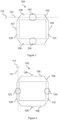
- a Helmholtz type tank 100 comprising parallel primary tubes 105 and 106 closed at their ends and interconnected by parallel secondary tubes 109 and 110.
- the primary tubes and the secondary tubes are perpendicular.
- acousto-electric transducers 103 and 104 In the middle of these primary tubes 105 and 106 are arranged acousto-electric transducers 103 and 104, respectively.
- the ends of the Primary tubes are windows 102 inclined relative to the main axes of the primary tubes to reflect acoustic signals from the primary tubes to the secondary tubes and vice versa.
- the windows 102 are transparent for the light wavelengths used.
- Gas inlets and outlets, respectively 107 and 108, constitute a means of introducing gas into the tank 100. These inlets and outlets are closed during operation of the device for detecting and measuring a quantity of gas.
- a first laser radiant energy source 112 provides excitation energy in the primary tube 105, at an emission wavelength corresponding to a locally maximum absorption wavelength for a first gas.
- the first laser radiant energy source 112 is positioned opposite a window closing one end of the primary tube 105.
- the first laser radiant energy source 112 is modulated at a first resonance frequency of the tank, to generate a first standing wave propagating along the secondary tubes 109 and 110.
- the first laser radiant energy source 112 when the first laser radiant energy source 112 is turned on, it heats the gas for which the emission wavelength of the first source 112 is an absorption wavelength. As it heats up, this gas generates an acoustic wave which propagates, through the secondary tubes 109 and 110, to the primary tube 106.
- the pressure variations inside the primary tube 106 therefore reflect the pressure variations inside the primary tube 106. interior of the primary tube 105, with a delay. Then, these pressure variations inside the primary tube 106 are reflected, via the secondary tubes 109 and 110, in the primary tube 105.
- the total duration of return of the pressure wave to the primary tube 105 corresponds at a period of a first resonance of the tank 100. The inverse of this first period is the first resonance frequency.
- the acousto-electric transducers 103 and 104 provide an electrical signal at the first resonance frequency and with an amplitude proportional to the quantity of the first desired gas present in the tank 100. By making the difference between these signals, we obtain a signal free of acoustic noise (which, by definition, is substantially in phase in the two primary tubes 105 and 106) of amplitude proportional to the quantity of the first gas sought.
- acousto-electric transducers 123 and 124 are arranged in the middle of the secondary tubes 109 and 110 in the middle of the secondary tubes 109 and 110 in the middle of the secondary tubes 109 and 110 in the middle of the secondary tubes 109 and 110 in the middle of the secondary tubes 109 and 110.
- Gas inlets and outlets, respectively 125 and 126, constitute a means of introducing gas into the tank 100. These inlets and outlets are closed during operation of the device for detecting and measuring a quantity of the gas.
- a second laser radiant energy source 117 provides excitation energy in the secondary tube 109, at an emission wavelength corresponding to a locally maximum absorption wavelength for a second gas, possibly identical to the first gas, the wavelength of the second source possibly being identical to the wavelength of the first source 112.
- the second laser radiant energy source 117 is positioned opposite a window closing one end of the primary tube 105.
- the second laser radiant energy source 117 is modulated at a second resonance frequency of the tank, to generate a second standing wave propagating along the primary tubes 105 and 106. It is observed that the second standing wave coincides with a node of this mode at the level of the transducers 103 and 104 so that the detection and measurement of the quantity of gas carried out from the signals coming from these transducers 103 and 104 are not disturbed by this second standing wave, whose working frequency of the mode Primary also intervenes at a frequency different from the secondary mode.
- the acousto-electric transducers 123 and 124 provide an electrical signal at the second resonance frequency and with an amplitude proportional to the quantity of the second desired gas present in the tank 100. By making the difference between these signals, we obtain a signal free of the noise acoustic and pressure variations linked to the first standing wave (which, by construction, is in phase in the two secondary tubes 109 and 110) of amplitude proportional to the quantity of the second gas sought.
- gas inlets and outlets are replaced by gas inlets and outlets, respectively 118 and 119, positioned near or on the surfaces inclined relative to the tube axes and making the junction between the primary tubes and the secondary tubes. These positions reduce the disturbances of the sound signals perceived by the acousto-electric transducers.
- the outgoing signals on the outputs 130 and 132 of these operational amplifiers 120 and 122 have amplitudes proportional to the quantities of gas exhibiting absorption of the wavelengths of the laser radiant energy sources 112 and 117.
- the detection and measuring device comprises two laser radiant energy sources facing two parallel tubes of the Helmholtz type tank. Said two laser radiant energy sources having emission wavelengths corresponding to absorption peaks of the same gas, possibly identical.
- the means of modulating the emission of these sources is adapted to simultaneously modulate the excitation energy supplied by the two laser radiant energy sources located opposite two different tubes by applying a phase shift of 180° between the energies excitation of said laser radiant energy sources.
- the modulation frequency of each of the radiant energy sources 112 and 117 is varied, from 400 Hz to 1400 Hz.
- the crosses 15 represent the amplitudes of the output signals of the transducers 123 and 124, which occur when the first Helmholtz mode is excited.
- the crosses 13 represent the differential measurement of the output signals of the transducers 103 and 104, in this first mode.
- points 16 represent the amplitudes of the output signals of transducers 103 and 104, which occur when the second Helmholtz mode is excited.
- Points 14 represent the differential measurement of the signals output from transducers 123 and 124 in this second mode.
- each of the standing waves does not constitute a parasitic wave for the other standing wave.
- the device which is the subject of the present invention allows operation on a Helmholtz type resonance at frequencies beyond kHz.
- the cell maintains dimensions compatible with simple coupling of the laser beam (collimation lens).
- the technological manufacturing constraints remain close to a macroscopic cell.
- the first resonance mode is used for the detection of a first gas and the second mode for the detection of a second gas.
- the device which is the subject of the present invention is mounted on a vehicle, the inlet tube 118 communicating with the exterior of the vehicle and drawing in air to perform the gas detections to be detected.
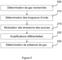
- the method comprises, firstly, a step 205 of determining the desired gases.
- the wavelengths of the radiant energy sources are determined which correspond to absorption peaks of the desired gases.
- step 215 the emissions of the radiant energy sources are modulated, respectively, at the resonance frequencies of the tank.
- the sound signals present in the different tubes are captured and differentially amplified.
- a step 225 as a function of this differential signal, we determine, for each gas sought, whether it is present in the tubes of the photo-acoustic device and we estimate the quantity of this gas as a function of the amplitude differential obtained.
Landscapes
- Physics & Mathematics (AREA)
- Health & Medical Sciences (AREA)
- Life Sciences & Earth Sciences (AREA)
- Chemical & Material Sciences (AREA)
- Analytical Chemistry (AREA)
- Biochemistry (AREA)
- General Health & Medical Sciences (AREA)
- General Physics & Mathematics (AREA)
- Immunology (AREA)
- Pathology (AREA)
- Investigating Or Analysing Materials By Optical Means (AREA)
Claims (8)
- Photoakustische Detektionsvorrichtung mindestens eines Gases, dadurch gekennzeichnet, dass sie umfasst:- einen Helmholtz-Resonator (100), bestehend aus zwei Primärrohren (105, 106), die an ihren Enden verschlossen und in der Nähe von beiden Enden durch zwei Sekundärrohre (109, 110) miteinander verbunden sind,- ein Mittel zum Einbringen von Gas (118, 119) in den Resonator,- mindestens eine erste Quelle (112) modulierter Laserstrahlungsenergie bei einer ersten Resonanzfrequenz des Resonators, die eine Anregungsenergie in mindestens einem der Primärrohre bei einer Emissionswellenlänge liefert, die einer lokal maximalen Absorptionswellenlänge für ein erstes Gas entspricht, wobei jede besagte erste Strahlungsenergiequelle gegenüber einem Fenster positioniert ist, das ein Ende des Primärrohrs schließt, um eine erste Stehwelle zu erzeugen, die sich entlang der Sekundärrohre ausbreitet,- mindestens eine zweite Quelle (117) modulierter Laserstrahlungsenergie bei einer zweiten Resonanzfrequenz des Resonators, die eine Anregungsenergie in mindestens einem der Sekundärrohre bei einer Emissionswellenlänge liefert, die einer lokal maximalen Absorptionswellenlänge für ein zweites Gas entspricht, wobei jede besagte erste Strahlungsenergiequelle gegenüber einem Fenster positioniert ist, das ein Ende des Primärrohrs schließt, um eine zweite Stehwelle zu erzeugen, die sich entlang der Primärrohre ausbreitet,- mindestens einen Schallwandler (103, 104, 123, 124), der an einer Wand jedes Rohrs angebracht ist, um die in diesem Rohr erzeugten akustischen Signale zu erfassen,- ein Mittel zur Verarbeitung (120) der Signale, die von den auf den Primärrohren angebrachten Wandlern kommen, um eine Amplitude der ersten Stehwelle zu extrahieren, und- ein Mittel zur Verarbeitung (122) der Signale, die von den auf den Sekundärrohren angebrachten Wandlern kommen, um eine Amplitude der zweite Stehwelle zu extrahieren.
- Vorrichtung nach Anspruch 1, wobei die Quellen (112, 117) der Laserstrahlungsenergie Emissionswellenlängen aufweisen, die Absorptionsspitzen desselben Gases entsprechen.
- Vorrichtung nach einem der Ansprüche 1 oder 2, wobei die Quellen (112, 117) der Laserstrahlungsenergie die gleiche Emissionswellenlänge haben.
- Vorrichtung nach einem der Ansprüche 1 bis 3, die zwei Laserstrahlungsenergiequellen gegenüber zwei parallelen Rohren des Helmholtz-Resonators umfasst, wobei die beiden Laserstrahlungsenergiequellen Emissionswellenlängen aufweisen, die Absorptionsspitzen desselben Gases entsprechen, die eventuell identisch sind. In dieser Vorrichtung ist das Modulationsmittel geeignet, die Anregungsenergie der beiden Laserstrahlungsenergiequellen, die sich gegenüber zwei verschiedenen Rohren befinden, gleichzeitig durch 180° Phasenverschiebung zwischen den Anregungsenergien der besagten Laserstrahlungsenergiequellen zu modulieren.
- Vorrichtung nach einem der Ansprüche 1 bis 4, wobei im Helmholtz-Resonator (100) die Enden der Primärrohre die Enden der Sekundärrohre berühren.
- Vorrichtung nach Anspruch 5, wobei die Rohrenden schräge Wände (102) in Bezug auf die Hauptachsen der Rohre aufweisen, um die Schallwellen von den Primärrohren zu den Sekundärrohren und umgekehrt zu reflektieren.
- Vorrichtung nach einem der Ansprüche 1 bis 6, wobei der Helmholtz-Resonator mindestens einen Gaseinlass (118) oder einen Gasauslass (119) an einer Endwand (102) eines Rohrs aufweist.
- Vorrichtung nach einem der Ansprüche 1 bis 7, wobei mindestens ein Mittel (120, 122) zur Verarbeitung von Signalen von auf parallelen Rohren angeordneten Wandlern einen Betriebsverstärker umfasst, wobei die Ausgangssignale der Wandler an die positiven und negativen Eingänge des Betriebsverstärkers angelegt werden.
Applications Claiming Priority (3)
| Application Number | Priority Date | Filing Date | Title |
|---|---|---|---|
| FR1560028A FR3042866A1 (fr) | 2015-10-21 | 2015-10-21 | Dispositif de detection de gaz a tres forte sensibilite base sur un resonateur de helmholtz |
| FR1560724A FR3042867B1 (fr) | 2015-10-21 | 2015-11-09 | Dispositif de detection de gaz a tres forte sensibilite base sur un resonateur de helmholtz |
| PCT/FR2016/052741 WO2017068301A1 (fr) | 2015-10-21 | 2016-10-21 | Dispositif de détection de gaz à très forte sensibilité base sur un résonateur de helmholtz |
Publications (3)
| Publication Number | Publication Date |
|---|---|
| EP3350571A1 EP3350571A1 (de) | 2018-07-25 |
| EP3350571B1 true EP3350571B1 (de) | 2023-12-06 |
| EP3350571C0 EP3350571C0 (de) | 2023-12-06 |
Family
ID=54979835
Family Applications (1)
| Application Number | Title | Priority Date | Filing Date |
|---|---|---|---|
| EP16806222.2A Active EP3350571B1 (de) | 2015-10-21 | 2016-10-21 | Vorrichtung auf basis eines helmholz-resonators zur detektion von gasen mit höher empfindlichkeit |
Country Status (4)
| Country | Link |
|---|---|
| US (1) | US10876958B2 (de) |
| EP (1) | EP3350571B1 (de) |
| FR (2) | FR3042866A1 (de) |
| WO (1) | WO2017068301A1 (de) |
Families Citing this family (8)
| Publication number | Priority date | Publication date | Assignee | Title |
|---|---|---|---|---|
| US20200182680A1 (en) * | 2018-12-06 | 2020-06-11 | Texas Instruments Incorporated | Metal tank ultrasonic liquid level sensing |
| US11408282B2 (en) * | 2019-05-10 | 2022-08-09 | Baker Hughes Oilfield Operations Llc | Bi-conical optical sensor for obtaining downhole fluid properties |
| US11661845B2 (en) | 2019-05-10 | 2023-05-30 | Baker Hughes Oilfield Operations Llc | Attenuated total internal reflection optical sensor for obtaining downhole fluid properties |
| CN112683808A (zh) * | 2020-12-15 | 2021-04-20 | 电子科技大学 | 一种基于光声谱多组分装置与信号处理方法 |
| CN112630165B (zh) * | 2021-01-07 | 2024-07-23 | 云南电网有限责任公司电力科学研究院 | 一种变压器油中气体检测装置 |
| CN115201116B (zh) * | 2022-09-15 | 2023-01-06 | 中国科学院合肥物质科学研究院 | 一种低噪声差分式亥姆霍兹光声光谱检测装置及方法 |
| CN116067890B (zh) * | 2023-02-16 | 2026-04-07 | 暨南大学 | 一种光声光谱测声器及气体探测装置 |
| CN116183514A (zh) * | 2023-04-06 | 2023-05-30 | 中国科学院半导体研究所 | 光声池及多组分气体检测系统 |
Citations (2)
| Publication number | Priority date | Publication date | Assignee | Title |
|---|---|---|---|---|
| FR2815122B1 (fr) * | 2000-10-06 | 2003-02-07 | Univ Reims Champagne Ardenne | Dispositif de detection de gaz |
| EP2515096B1 (de) * | 2011-04-21 | 2013-08-28 | Commissariat A L'energie Atomique Et Aux Energies Alternatives | Fotoakustischer Gasdetektor mit Helmholtzelle |
Family Cites Families (9)
| Publication number | Priority date | Publication date | Assignee | Title |
|---|---|---|---|---|
| JPS59145957A (ja) * | 1983-01-08 | 1984-08-21 | Horiba Ltd | 光音響型濃度測定装置 |
| US5933245A (en) * | 1996-12-31 | 1999-08-03 | Honeywell Inc. | Photoacoustic device and process for multi-gas sensing |
| PL354646A1 (en) * | 2000-10-09 | 2004-02-09 | Siemens Building Technologies Ag | Optoacoustic measuring arrangement and use thereof |
| US7069769B2 (en) * | 2004-01-20 | 2006-07-04 | Academia Sinica | Ultraviolet photoacoustic ozone detection |
| CA2461328A1 (en) * | 2004-03-24 | 2005-09-24 | Robert Anthony Crane | A multiplexed type of spectrophone |
| US8437000B2 (en) * | 2010-06-29 | 2013-05-07 | Honeywell International Inc. | Multiple wavelength cavity ring down gas sensor |
| FR2963102B1 (fr) * | 2010-07-21 | 2017-01-13 | Univ Reims Champagne Ardenne | Procede et dispositif de detection de traces de gaz multiples |
| FR3019653B1 (fr) * | 2014-04-08 | 2016-05-13 | Commissariat Energie Atomique | Dispositif de detection a resonateur acoustique differentiel de type helmholtz |
| FR3037145B1 (fr) * | 2015-06-08 | 2020-03-13 | Commissariat A L'energie Atomique Et Aux Energies Alternatives | Dispositif de detection photoacoustique modulaire |
-
2015
- 2015-10-21 FR FR1560028A patent/FR3042866A1/fr active Pending
- 2015-11-09 FR FR1560724A patent/FR3042867B1/fr not_active Expired - Fee Related
-
2016
- 2016-10-21 WO PCT/FR2016/052741 patent/WO2017068301A1/fr not_active Ceased
- 2016-10-21 EP EP16806222.2A patent/EP3350571B1/de active Active
- 2016-10-21 US US15/769,516 patent/US10876958B2/en active Active
Patent Citations (2)
| Publication number | Priority date | Publication date | Assignee | Title |
|---|---|---|---|---|
| FR2815122B1 (fr) * | 2000-10-06 | 2003-02-07 | Univ Reims Champagne Ardenne | Dispositif de detection de gaz |
| EP2515096B1 (de) * | 2011-04-21 | 2013-08-28 | Commissariat A L'energie Atomique Et Aux Energies Alternatives | Fotoakustischer Gasdetektor mit Helmholtzelle |
Also Published As
| Publication number | Publication date |
|---|---|
| FR3042866A1 (fr) | 2017-04-28 |
| WO2017068301A1 (fr) | 2017-04-27 |
| EP3350571A1 (de) | 2018-07-25 |
| US10876958B2 (en) | 2020-12-29 |
| FR3042867B1 (fr) | 2017-11-24 |
| EP3350571C0 (de) | 2023-12-06 |
| US20180306704A1 (en) | 2018-10-25 |
| FR3042867A1 (fr) | 2017-04-28 |
Similar Documents
| Publication | Publication Date | Title |
|---|---|---|
| WO2017068301A1 (fr) | Dispositif de détection de gaz à très forte sensibilité base sur un résonateur de helmholtz | |
| Chen et al. | Fiber-amplifier-enhanced resonant photoacoustic sensor for sub-ppb level acetylene detection | |
| Chen et al. | Highly sensitive photoacoustic gas sensor based on multiple reflections on the cell wall | |
| Zhang et al. | Photoacoustic spectroscopy for detection of trace C2H2 using ellipsoidal photoacoustic cell | |
| US7782462B2 (en) | Sono-photonic gas sensor | |
| CN110044824A (zh) | 一种基于石英音叉的双光谱气体检测装置及方法 | |
| CN114002184B (zh) | 多谐振增强型光声光谱多组分气体同时检测装置及方法 | |
| Lindley et al. | A sensitivity comparison of three photoacoustic cells containing a single microphone, a differential dual microphone or a cantilever pressure sensor | |
| EP3527967B1 (de) | Akustooptischer detektor mit optomechanischer kopplung | |
| Zhang et al. | Advances in differential photoacoustic spectroscopy for trace gas detection | |
| FR2963102A1 (fr) | Procede et dispositif de detection de traces de gaz multiples | |
| Helman et al. | Off-beam quartz-enhanced photoacoustic spectroscopy-based sensor for hydrogen sulfide trace gas detection using a mode-hop-free external cavity quantum cascade laser | |
| CN112924388A (zh) | 正交双通道声学谐振模块及包括该模块的装置 | |
| CN107560730A (zh) | 双腔式光声光谱仪 | |
| Shang et al. | Theoretical analysis and experimental optimization of an elliptical acoustic resonator in quartz-enhanced photoacoustic spectroscopy | |
| CN112630165B (zh) | 一种变压器油中气体检测装置 | |
| CN103592225B (zh) | 土壤红外光声光谱快速测定仪及其土壤理化性质测定方法 | |
| FR3017950A1 (fr) | Dispositif d'analyse de gaz a tres forte sensibilite | |
| Zhang et al. | Detecting acetylene (C2H2) dissolved in transformer oil using optimized photoacoustic spectroscopy | |
| Fathy et al. | Silicon multipass cells for localized multi-parameter gas sensing by absorption spectroscopy | |
| EP2954311A1 (de) | Photoakustische zelle mit verbesserter nachweisgenauigkeit und gasanalysator mit solch einer zelle | |
| KR102269015B1 (ko) | 가스측정용 음향센서 | |
| CH719928A2 (fr) | Analyseur photo-acoustique. | |
| CN121632973B (zh) | 一种基于串联增敏技术的光声气体测量方法及系统 | |
| Schmitt et al. | Resonant photoacoustic cells for laser-based methane detection |
Legal Events
| Date | Code | Title | Description |
|---|---|---|---|
| STAA | Information on the status of an ep patent application or granted ep patent |
Free format text: STATUS: UNKNOWN |
|
| STAA | Information on the status of an ep patent application or granted ep patent |
Free format text: STATUS: THE INTERNATIONAL PUBLICATION HAS BEEN MADE |
|
| PUAI | Public reference made under article 153(3) epc to a published international application that has entered the european phase |
Free format text: ORIGINAL CODE: 0009012 |
|
| STAA | Information on the status of an ep patent application or granted ep patent |
Free format text: STATUS: REQUEST FOR EXAMINATION WAS MADE |
|
| 17P | Request for examination filed |
Effective date: 20180418 |
|
| AK | Designated contracting states |
Kind code of ref document: A1 Designated state(s): AL AT BE BG CH CY CZ DE DK EE ES FI FR GB GR HR HU IE IS IT LI LT LU LV MC MK MT NL NO PL PT RO RS SE SI SK SM TR |
|
| AX | Request for extension of the european patent |
Extension state: BA ME |
|
| GRAP | Despatch of communication of intention to grant a patent |
Free format text: ORIGINAL CODE: EPIDOSNIGR1 |
|
| STAA | Information on the status of an ep patent application or granted ep patent |
Free format text: STATUS: GRANT OF PATENT IS INTENDED |
|
| RIC1 | Information provided on ipc code assigned before grant |
Ipc: G01N 21/17 20060101AFI20190425BHEP Ipc: G01N 21/05 20060101ALI20190425BHEP |
|
| INTG | Intention to grant announced |
Effective date: 20190527 |
|
| RAP1 | Party data changed (applicant data changed or rights of an application transferred) |
Owner name: C.N.R.S. Owner name: AEROVIA Owner name: UNIVERSITE DE REIMS CHAMPAGNE ARDENNE |
|
| 19U | Interruption of proceedings before grant |
Effective date: 20180904 |
|
| 19W | Proceedings resumed before grant after interruption of proceedings |
Effective date: 20230403 |
|
| PUAJ | Public notification under rule 129 epc |
Free format text: ORIGINAL CODE: 0009425 |
|
| 32PN | Public notification |
Free format text: NOTIFICATION ETABLIE CONFORMEMENT A LA REGLE 142 CBE (REPRISE DE LA PROCEDURE CONFORMEMENT A LA REGLE 142 (2) CBE EN DATE DU 27.10.2022) |
|
| GRAJ | Information related to disapproval of communication of intention to grant by the applicant or resumption of examination proceedings by the epo deleted |
Free format text: ORIGINAL CODE: EPIDOSDIGR1 |
|
| STAA | Information on the status of an ep patent application or granted ep patent |
Free format text: STATUS: REQUEST FOR EXAMINATION WAS MADE |
|
| GRAP | Despatch of communication of intention to grant a patent |
Free format text: ORIGINAL CODE: EPIDOSNIGR1 |
|
| STAA | Information on the status of an ep patent application or granted ep patent |
Free format text: STATUS: GRANT OF PATENT IS INTENDED |
|
| INTC | Intention to grant announced (deleted) | ||
| RAP3 | Party data changed (applicant data changed or rights of an application transferred) |
Owner name: C.N.R.S. Owner name: UNIVERSITE DE REIMS CHAMPAGNE-ARDENNE Owner name: AEROVIA |
|
| DAV | Request for validation of the european patent (deleted) | ||
| DAX | Request for extension of the european patent (deleted) | ||
| INTG | Intention to grant announced |
Effective date: 20230802 |
|
| GRAS | Grant fee paid |
Free format text: ORIGINAL CODE: EPIDOSNIGR3 |
|
| GRAA | (expected) grant |
Free format text: ORIGINAL CODE: 0009210 |
|
| STAA | Information on the status of an ep patent application or granted ep patent |
Free format text: STATUS: THE PATENT HAS BEEN GRANTED |
|
| AK | Designated contracting states |
Kind code of ref document: B1 Designated state(s): AL AT BE BG CH CY CZ DE DK EE ES FI FR GB GR HR HU IE IS IT LI LT LU LV MC MK MT NL NO PL PT RO RS SE SI SK SM TR |
|
| REG | Reference to a national code |
Ref country code: GB Ref legal event code: FG4D Free format text: NOT ENGLISH |
|
| REG | Reference to a national code |
Ref country code: CH Ref legal event code: EP |
|
| REG | Reference to a national code |
Ref country code: DE Ref legal event code: R096 Ref document number: 602016084605 Country of ref document: DE |
|
| REG | Reference to a national code |
Ref country code: IE Ref legal event code: FG4D Free format text: LANGUAGE OF EP DOCUMENT: FRENCH |
|
| U01 | Request for unitary effect filed |
Effective date: 20240105 |
|
| U07 | Unitary effect registered |
Designated state(s): AT BE BG DE DK EE FI FR IT LT LU LV MT NL PT SE SI Effective date: 20240117 |
|
| PG25 | Lapsed in a contracting state [announced via postgrant information from national office to epo] |
Ref country code: GR Free format text: LAPSE BECAUSE OF FAILURE TO SUBMIT A TRANSLATION OF THE DESCRIPTION OR TO PAY THE FEE WITHIN THE PRESCRIBED TIME-LIMIT Effective date: 20240307 |
|
| PG25 | Lapsed in a contracting state [announced via postgrant information from national office to epo] |
Ref country code: ES Free format text: LAPSE BECAUSE OF FAILURE TO SUBMIT A TRANSLATION OF THE DESCRIPTION OR TO PAY THE FEE WITHIN THE PRESCRIBED TIME-LIMIT Effective date: 20231206 |
|
| PG25 | Lapsed in a contracting state [announced via postgrant information from national office to epo] |
Ref country code: GR Free format text: LAPSE BECAUSE OF FAILURE TO SUBMIT A TRANSLATION OF THE DESCRIPTION OR TO PAY THE FEE WITHIN THE PRESCRIBED TIME-LIMIT Effective date: 20240307 Ref country code: ES Free format text: LAPSE BECAUSE OF FAILURE TO SUBMIT A TRANSLATION OF THE DESCRIPTION OR TO PAY THE FEE WITHIN THE PRESCRIBED TIME-LIMIT Effective date: 20231206 |
|
| PG25 | Lapsed in a contracting state [announced via postgrant information from national office to epo] |
Ref country code: RS Free format text: LAPSE BECAUSE OF FAILURE TO SUBMIT A TRANSLATION OF THE DESCRIPTION OR TO PAY THE FEE WITHIN THE PRESCRIBED TIME-LIMIT Effective date: 20231206 Ref country code: NO Free format text: LAPSE BECAUSE OF FAILURE TO SUBMIT A TRANSLATION OF THE DESCRIPTION OR TO PAY THE FEE WITHIN THE PRESCRIBED TIME-LIMIT Effective date: 20240306 Ref country code: HR Free format text: LAPSE BECAUSE OF FAILURE TO SUBMIT A TRANSLATION OF THE DESCRIPTION OR TO PAY THE FEE WITHIN THE PRESCRIBED TIME-LIMIT Effective date: 20231206 |
|
| PG25 | Lapsed in a contracting state [announced via postgrant information from national office to epo] |
Ref country code: IS Free format text: LAPSE BECAUSE OF FAILURE TO SUBMIT A TRANSLATION OF THE DESCRIPTION OR TO PAY THE FEE WITHIN THE PRESCRIBED TIME-LIMIT Effective date: 20240406 |
|
| PG25 | Lapsed in a contracting state [announced via postgrant information from national office to epo] |
Ref country code: CZ Free format text: LAPSE BECAUSE OF FAILURE TO SUBMIT A TRANSLATION OF THE DESCRIPTION OR TO PAY THE FEE WITHIN THE PRESCRIBED TIME-LIMIT Effective date: 20231206 |
|
| PG25 | Lapsed in a contracting state [announced via postgrant information from national office to epo] |
Ref country code: SK Free format text: LAPSE BECAUSE OF FAILURE TO SUBMIT A TRANSLATION OF THE DESCRIPTION OR TO PAY THE FEE WITHIN THE PRESCRIBED TIME-LIMIT Effective date: 20231206 |
|
| PG25 | Lapsed in a contracting state [announced via postgrant information from national office to epo] |
Ref country code: SM Free format text: LAPSE BECAUSE OF FAILURE TO SUBMIT A TRANSLATION OF THE DESCRIPTION OR TO PAY THE FEE WITHIN THE PRESCRIBED TIME-LIMIT Effective date: 20231206 Ref country code: SK Free format text: LAPSE BECAUSE OF FAILURE TO SUBMIT A TRANSLATION OF THE DESCRIPTION OR TO PAY THE FEE WITHIN THE PRESCRIBED TIME-LIMIT Effective date: 20231206 Ref country code: RO Free format text: LAPSE BECAUSE OF FAILURE TO SUBMIT A TRANSLATION OF THE DESCRIPTION OR TO PAY THE FEE WITHIN THE PRESCRIBED TIME-LIMIT Effective date: 20231206 Ref country code: IS Free format text: LAPSE BECAUSE OF FAILURE TO SUBMIT A TRANSLATION OF THE DESCRIPTION OR TO PAY THE FEE WITHIN THE PRESCRIBED TIME-LIMIT Effective date: 20240406 Ref country code: CZ Free format text: LAPSE BECAUSE OF FAILURE TO SUBMIT A TRANSLATION OF THE DESCRIPTION OR TO PAY THE FEE WITHIN THE PRESCRIBED TIME-LIMIT Effective date: 20231206 |
|
| PG25 | Lapsed in a contracting state [announced via postgrant information from national office to epo] |
Ref country code: PL Free format text: LAPSE BECAUSE OF FAILURE TO SUBMIT A TRANSLATION OF THE DESCRIPTION OR TO PAY THE FEE WITHIN THE PRESCRIBED TIME-LIMIT Effective date: 20231206 |
|
| PG25 | Lapsed in a contracting state [announced via postgrant information from national office to epo] |
Ref country code: PL Free format text: LAPSE BECAUSE OF FAILURE TO SUBMIT A TRANSLATION OF THE DESCRIPTION OR TO PAY THE FEE WITHIN THE PRESCRIBED TIME-LIMIT Effective date: 20231206 |
|
| REG | Reference to a national code |
Ref country code: DE Ref legal event code: R097 Ref document number: 602016084605 Country of ref document: DE |
|
| PLBE | No opposition filed within time limit |
Free format text: ORIGINAL CODE: 0009261 |
|
| STAA | Information on the status of an ep patent application or granted ep patent |
Free format text: STATUS: NO OPPOSITION FILED WITHIN TIME LIMIT |
|
| 26N | No opposition filed |
Effective date: 20240909 |
|
| U20 | Renewal fee for the european patent with unitary effect paid |
Year of fee payment: 9 Effective date: 20241030 |
|
| PG25 | Lapsed in a contracting state [announced via postgrant information from national office to epo] |
Ref country code: MC Free format text: LAPSE BECAUSE OF FAILURE TO SUBMIT A TRANSLATION OF THE DESCRIPTION OR TO PAY THE FEE WITHIN THE PRESCRIBED TIME-LIMIT Effective date: 20231206 |
|
| PG25 | Lapsed in a contracting state [announced via postgrant information from national office to epo] |
Ref country code: IE Free format text: LAPSE BECAUSE OF NON-PAYMENT OF DUE FEES Effective date: 20241021 |
|
| REG | Reference to a national code |
Ref country code: CH Ref legal event code: U11 Free format text: ST27 STATUS EVENT CODE: U-0-0-U10-U11 (AS PROVIDED BY THE NATIONAL OFFICE) Effective date: 20251106 |
|
| U20 | Renewal fee for the european patent with unitary effect paid |
Year of fee payment: 10 Effective date: 20251030 |
|
| PGFP | Annual fee paid to national office [announced via postgrant information from national office to epo] |
Ref country code: GB Payment date: 20251029 Year of fee payment: 10 |
|
| PGFP | Annual fee paid to national office [announced via postgrant information from national office to epo] |
Ref country code: CH Payment date: 20251106 Year of fee payment: 10 |
|
| PG25 | Lapsed in a contracting state [announced via postgrant information from national office to epo] |
Ref country code: CY Free format text: LAPSE BECAUSE OF FAILURE TO SUBMIT A TRANSLATION OF THE DESCRIPTION OR TO PAY THE FEE WITHIN THE PRESCRIBED TIME-LIMIT; INVALID AB INITIO Effective date: 20161021 |
|
| PG25 | Lapsed in a contracting state [announced via postgrant information from national office to epo] |
Ref country code: HU Free format text: LAPSE BECAUSE OF FAILURE TO SUBMIT A TRANSLATION OF THE DESCRIPTION OR TO PAY THE FEE WITHIN THE PRESCRIBED TIME-LIMIT; INVALID AB INITIO Effective date: 20161021 |