EP3350520B1 - Drainage tray for a heat pump - Google Patents
Drainage tray for a heat pump Download PDFInfo
- Publication number
- EP3350520B1 EP3350520B1 EP16846963.3A EP16846963A EP3350520B1 EP 3350520 B1 EP3350520 B1 EP 3350520B1 EP 16846963 A EP16846963 A EP 16846963A EP 3350520 B1 EP3350520 B1 EP 3350520B1
- Authority
- EP
- European Patent Office
- Prior art keywords
- tray
- support
- heat pump
- drainage
- condensate
- Prior art date
- Legal status (The legal status is an assumption and is not a legal conclusion. Google has not performed a legal analysis and makes no representation as to the accuracy of the status listed.)
- Active
Links
Images


Classifications
-
- F—MECHANICAL ENGINEERING; LIGHTING; HEATING; WEAPONS; BLASTING
- F24—HEATING; RANGES; VENTILATING
- F24F—AIR-CONDITIONING; AIR-HUMIDIFICATION; VENTILATION; USE OF AIR CURRENTS FOR SCREENING
- F24F1/00—Room units for air-conditioning, e.g. separate or self-contained units or units receiving primary air from a central station
- F24F1/06—Separate outdoor units, e.g. outdoor unit to be linked to a separate room comprising a compressor and a heat exchanger
- F24F1/36—Drip trays for outdoor units
-
- F—MECHANICAL ENGINEERING; LIGHTING; HEATING; WEAPONS; BLASTING
- F25—REFRIGERATION OR COOLING; COMBINED HEATING AND REFRIGERATION SYSTEMS; HEAT PUMP SYSTEMS; MANUFACTURE OR STORAGE OF ICE; LIQUEFACTION SOLIDIFICATION OF GASES
- F25D—REFRIGERATORS; COLD ROOMS; ICE-BOXES; COOLING OR FREEZING APPARATUS NOT OTHERWISE PROVIDED FOR
- F25D21/00—Defrosting; Preventing frosting; Removing condensed or defrost water
- F25D21/14—Collecting or removing condensed and defrost water; Drip trays
-
- F—MECHANICAL ENGINEERING; LIGHTING; HEATING; WEAPONS; BLASTING
- F24—HEATING; RANGES; VENTILATING
- F24D—DOMESTIC- OR SPACE-HEATING SYSTEMS, e.g. CENTRAL HEATING SYSTEMS; DOMESTIC HOT-WATER SUPPLY SYSTEMS; ELEMENTS OR COMPONENTS THEREFOR
- F24D19/00—Details
- F24D19/08—Arrangements for drainage, venting or aerating
-
- F—MECHANICAL ENGINEERING; LIGHTING; HEATING; WEAPONS; BLASTING
- F24—HEATING; RANGES; VENTILATING
- F24F—AIR-CONDITIONING; AIR-HUMIDIFICATION; VENTILATION; USE OF AIR CURRENTS FOR SCREENING
- F24F11/00—Control or safety arrangements
- F24F11/30—Control or safety arrangements for purposes related to the operation of the system, e.g. for safety or monitoring
- F24F11/41—Defrosting; Preventing freezing
- F24F11/42—Defrosting; Preventing freezing of outdoor units
-
- F—MECHANICAL ENGINEERING; LIGHTING; HEATING; WEAPONS; BLASTING
- F24—HEATING; RANGES; VENTILATING
- F24F—AIR-CONDITIONING; AIR-HUMIDIFICATION; VENTILATION; USE OF AIR CURRENTS FOR SCREENING
- F24F13/00—Details common to, or for air-conditioning, air-humidification, ventilation or use of air currents for screening
- F24F13/22—Means for preventing condensation or evacuating condensate
- F24F13/222—Means for preventing condensation or evacuating condensate for evacuating condensate
-
- F—MECHANICAL ENGINEERING; LIGHTING; HEATING; WEAPONS; BLASTING
- F28—HEAT EXCHANGE IN GENERAL
- F28F—DETAILS OF HEAT-EXCHANGE AND HEAT-TRANSFER APPARATUS, OF GENERAL APPLICATION
- F28F17/00—Removing ice or water from heat-exchange apparatus
- F28F17/005—Means for draining condensates from heat exchangers, e.g. from evaporators
-
- F—MECHANICAL ENGINEERING; LIGHTING; HEATING; WEAPONS; BLASTING
- F24—HEATING; RANGES; VENTILATING
- F24F—AIR-CONDITIONING; AIR-HUMIDIFICATION; VENTILATION; USE OF AIR CURRENTS FOR SCREENING
- F24F1/00—Room units for air-conditioning, e.g. separate or self-contained units or units receiving primary air from a central station
- F24F1/06—Separate outdoor units, e.g. outdoor unit to be linked to a separate room comprising a compressor and a heat exchanger
- F24F1/40—Vibration or noise prevention at outdoor units
-
- F—MECHANICAL ENGINEERING; LIGHTING; HEATING; WEAPONS; BLASTING
- F24—HEATING; RANGES; VENTILATING
- F24F—AIR-CONDITIONING; AIR-HUMIDIFICATION; VENTILATION; USE OF AIR CURRENTS FOR SCREENING
- F24F1/00—Room units for air-conditioning, e.g. separate or self-contained units or units receiving primary air from a central station
- F24F1/06—Separate outdoor units, e.g. outdoor unit to be linked to a separate room comprising a compressor and a heat exchanger
- F24F1/60—Arrangement or mounting of the outdoor unit
-
- F—MECHANICAL ENGINEERING; LIGHTING; HEATING; WEAPONS; BLASTING
- F24—HEATING; RANGES; VENTILATING
- F24F—AIR-CONDITIONING; AIR-HUMIDIFICATION; VENTILATION; USE OF AIR CURRENTS FOR SCREENING
- F24F13/00—Details common to, or for air-conditioning, air-humidification, ventilation or use of air currents for screening
- F24F13/22—Means for preventing condensation or evacuating condensate
- F24F13/222—Means for preventing condensation or evacuating condensate for evacuating condensate
- F24F2013/227—Condensate pipe for drainage of condensate from the evaporator
-
- F—MECHANICAL ENGINEERING; LIGHTING; HEATING; WEAPONS; BLASTING
- F24—HEATING; RANGES; VENTILATING
- F24F—AIR-CONDITIONING; AIR-HUMIDIFICATION; VENTILATION; USE OF AIR CURRENTS FOR SCREENING
- F24F2221/00—Details or features not otherwise provided for
- F24F2221/34—Heater, e.g. gas burner, electric air heater
Definitions
- the present invention relates to heat pumps for providing heating and/or cooling to a destination, more specifically for air source heat pumps for providing heating and/or cooling to a building or a part of a building, and even more specifically to a drainage tray for removing condensate which is produced by the heat pump.
- Heat pumps are commonly used for providing heating or cooling to buildings, i.e. HVAC applications, due to their relatively low running costs and friendliness to the environment. Development has for several years been trending towards many households and business buildings switching from aging more expensive HVAC systems to a heat pump based system, such that the heat pump alone provides the heating or complements the older system.
- Heat pumps use refrigeration cycles in which a refrigerant is used for collecting and delivering heat.
- the heat pumps may be reversible, i.e. the condenser and the evaporator may switch functionality.
- Air source heat pumps generally comprise an outdoor unit.
- a known problem with this unit is that it generates a lot of condensate, and as development leads to more efficient heat pumps, even more condensate is produced.
- Many heat pumps lack a built in solution for taking care of the condensate, and therefore rely on external trays which are fitted below the heat pump. These are however sensitive to freezing of the condensate and to debris such as leaves clogging the outlet of the tray.
- the European patent application EP 2 636 966 A1 discloses a drainage tray according to the preamble of claim 1, adapted to be installed underneath an outdoor unit of an air conditioner or heat pump.
- a drainage tray for collecting condensate from a heat pump is provided.
- the heat pump is adapted to be mounted on a support, said support being mountable to at least one supporting structure (such as the ground and/or an external building wall) to carry the weight of the heat pump and the support.
- the tray comprises a peripheral and preferably inclined edge portion defining a central recessed tray portion configured to collect condensate, and the tray further comprises a condensate outlet for removing the condensate from the tray.
- the tray is configured to be arranged between an underside of the heat pump and the support. Since the distance between the tray and the heat pump is minimized, the risk of freezing condensate, spilling of condensate and debris falling into the tray is reduced, and a tray which is improved over prior art is thereby provided.
- the drainage tray further comprises at least two lateral recessed portions on the opposite side of the tray in relation to the central recessed portion.
- the lateral recessed portions essentially correspond to supporting members on the support such that the tray is supported by the contact between the at least two lateral recessed portions and the support.
- the lateral recessed portions are shaped and positioned for securing the tray and preventing sideways motions in the longitudinal direction of the tray.
- the at least two lateral recessed portions further comprise a rubber coating covering at least a part of the at least two lateral recessed portions for increasing friction between the tray and the support.
- the rubber coating provides dampening of any noise that might be caused by vibrations or by wind and increases the friction between the tray and the support.
- a first of the lateral recessed portions is adapted for restricting motion of the tray in two directions and a second of the lateral recessed portions is adapted for restricting motion of the tray in one direction.
- the different shape of the first and second recessed portions will facilitate insertion and removal of the tray and also provide larger dimensional span of the supports which support the tray will fit onto.
- the drainage tray has an essentially trapezoidal shape in a horizontal plane, i.e. a plane parallel to the underside of the heat pump.
- the shape of the tray corresponds to the L-shaped condenser of many heat pumps. It is possible to adapt the tray according to shape of the condenser since the vicinity of the tray to the heat pump reduces the effect of wind or other external forces on the drops of condensate.
- the drainage tray comprises a top tray portion and a bottom tray portion.
- the top and bottom portions are connected along a peripheral edge of the tray, and a hollow centre portion is formed within the tray between the top and bottom portions.
- the hollow centre portion provides an insulating air layer between the central recessed portion and the bottom portion which is in contact with the support.
- an electrically heated sheet is arranged within the hollow portion, said sheet being attached to the underside of the top tray portion such that it evenly heats the central recessed portion of the tray avoiding freezing of the condensate.
- the heated sheet keeps the condensate from freezing and heats the central recessed portion and even at least a part of the inclined edge portion.
- an insulating sheet is arranged within the hollow portion, said sheet being attached to the top side of the bottom tray portion.
- the insulating sheet increases the efficiency of the tray in combination with the electrically heated sheet.
- the insulating sheet is spaced from the heating sheet within the hollow portion such that further insulation is provided by intermediate air between the insulating sheet and the electrically heated sheet.
- the drainage tray is made from a polymer material, preferably ABS/PMMA.
- a hose is connectable to the outlet of the tray, said hose being insulated and configured to be heated by an internal heating element.
- the recessed portion for collecting condensate is configured to hold a volume of at least 1,2 1 condensate, and more preferably at least 1,4 1 condensate.
- the volume of the central recessed portion provides a buffer volume which is beneficial if for instance if a blockage occurs in the outlet of the tray or in the hose.
- the drainage tray has a height of between 20 and 30 mm, preferably 25 mm.
- a heat pump system comprising a heat pump, a support and a drainage tray according to the first aspect, wherein the heat pump is arranged on the support via bushings having a height of between 25 and 40 mm, more preferably between 30 and 35 mm and even more preferably 30 mm, said bushings creating a space between the underside of the heat pump and the support configured for receiving the tray.
- a heat pump system 1 is shown.
- the heat pump 3 is positioned on a support 4.
- the support is mounted to or resting on a supporting structure, in Fig. 1 this is the ground and an optional wall behind the support for further stability.
- the supporting structure is defined as the structure or structures which bear the load from the heat pump and the support.
- the support 4 could also be a wall mounted support, where the only supporting structure is a wall.
- the support 4 comprises a plurality of supporting members 5, onto which the heat pump 3 is mounted.
- the support 4 is preferably made out of metal, such as galvanized steel, stainless steel, aluminium or another metal with high corrosion resistance. Other materials are also possible, such as plastics or composite materials.
- the heat pump 3 shown is an outdoor unit which is adapted to be connected to an indoor unit for providing heat or cooling and regulating the indoor climate.
- the heat pump 3 may be mounted onto the support 4 via bushings 7 attached either directly to the underside of the heat pump 3 or to heat pump mounting feet 17 which are attached to the heat pump 3.
- the bushings 7 are made of a resilient material, such as rubber, and intended to absorb and reduce the risk of any possible vibrations in the heat pump 3 being transferred to the support 4 and onwards to the supporting structure.
- the bushings 7 have a height of between 25 and 40 mm, more preferably between 30 and 35 mm and even more preferably 30 mm. Thus a space is provided between the underside of the pump 3 or the mounting feet 17 of the pump and the support 4 which essentially corresponds to the height of the bushings 7.
- the space between the pump 3 and the support 4 is adapted for receiving a drainage tray 2 according to the teachings herein.
- the drainage tray 2 is adapted to receive the condensate which is being produced by the pump 3 and which drips from drainage holes in the underside of the pump 3.
- the tray 2 can be brought closer to the underside of the pump 3. This is an advantage since it will reduce the falling distance for condensate drops from the pump 3, which reduces the risk of drops being affected by wind such that they fall to the side of the tray. The risk of condensate freezing during cold temperatures also decreases.
- a small distance between the tray 2 and the underside of the pump 3 is also an advantage since it reduces the risk of debris such as leaves landing in the tray 3.
- the tray further comprises a hose 6 for removing the condensate from the tray 2.
- the hose may comprise insulation and may furthermore be configured to be heated by a heating element, such as a heating cable, to ensure that the condensate does not freeze in the hose.
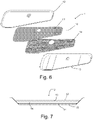
- a perspective view is shown of a drainage tray 2 according to the teachings herein.
- the tray 2 has an essentially trapezoidal, oblong shape in a horizontal plane i.e. in a plane parallel to the underside of the heat pump.
- the shape is however not limited to an ideal trapezoidal shape, as a rectangular portion may be arranged on the wider part of the trapezoidal.
- Many of the leading manufacturers of heat pumps use L-shaped condensers, when seen from above, which are positioned in the heat pumps 3 in similar manners.
- the shape of the tray 2 can thereby be optimized, as the drops will fall from the condenser through the holes in the underside of the pump 3 in an essentially L-shaped pattern. This is made possible by the tray 2 being brought closer to the pump 3, ensuring that the drops of condensate will fall straight down into the tray 2.
- An advantage with the optimized shape is the reduced manufacturing cost due to less material being required for the tray.
- the tray 2 further comprises an outlet 9, through which the collected condensate drains.
- the hose 6 is connectable to the outlet 9 for instance by means of a threaded connection or a quick lock connection.
- the tray 2 also comprises a peripheral inclined edge portion 7 forming a central recessed tray portion 8.
- the inclined edge portion 7 prevents the condensate from spilling off the side of the tray, and the central recessed tray portion 8 which faces the underside of the pump 3 can hold a certain volume of condensate. This is beneficial since if a blockage occurs in the outlet 9 or in the hose 6, the recessed tray portion 8 will function as a buffering volume, providing a longer time span until condensate overflows the inclined edge portion 7.
- the volume of the central recessed portion 8 is at least 1,2 1 in the disclosed embodiment, more preferably more than 1,4 1.
- the volume is preferably in the range of 1 1 - 1,6 1.
- the inclined edge portion 7 has an incline of approximately 35° to 55° in the disclosed embodiment or more preferably approximately 45° in relation the surface in the central recessed portion 8.
- the tray 2 is shown as seen from above with an outline 19 of a how the L-shaped condenser in a heat pump is oriented in relation to the tray 2.
- the shape of the tray 2 is optimized in relation to the condenser, thus using less material in the manufacturing of the tray 2 whilst maintaining or improving functionality.
- a side view and bottom view of the tray 2 are shown.
- the tray 2 has at least two lateral recessed portions 10, 11, which essentially correspond to the supporting members 5 on the support 4.
- the recessed portions 10, 11 are on the opposite side of the tray 2 in relation to the central recessed portion 8. As the tray 2 is placed on the support 4, the tray will rest on and be held in place by the contact between the portions 10, 11 and the support 4.
- a first 10 of the lateral recessed portions is adapted for restricting motion of the tray in two directions
- a second 11 of the lateral recessed portions 10, 11 is adapted for restricting motion of the tray in one direction.
- the first lateral recessed portion 10 comprises two edges being transverse to the longitudinal direction of the tray 2 while the second lateral recessed portion 11 only comprises one transverse edge that will limit the motion of the tray 2.
- the support of the tray 2 may be further facilitated by provision of a rubber coating to the lateral recessed portions 10, 11.
- the rubber coating will provide increased friction between the tray 2 and the support 4, and also reduce any noise that the tray 2 may cause due to possible vibrations caused by moving parts in the pump 3.
- the rubber coating may be a rubber sheet which is applied by an adhesive such as glue or tape, i.e. laminated onto the tray 2.
- the rubber coating may also be applied in the manufacturing process of the tray 2, for instance as a part of a thermoforming or injection molding process.
- the height of the tray 2 is between 20 mm and 30 mm in the disclosed embodiment, preferably approximately 25 mm such that it can fit between the pump 3 and the support 4.
- the tray 2 comprises a top portion 12 and a bottom portion 15.
- the top 12 and bottom 15 portions are connected along a peripheral edge of the tray 2, for instance by means of welding and/or gluing.
- the top and bottom portions 12, 15 may be manufactured in a thermoforming process or in an injection molding process. Other manufacturing processes are however also possible.
- the top 12 and bottom 15 portions form between them a hollow portion 16, in which an insulating sheet 14 and/or a electrically heated sheet 13 may be arranged.
- the insulating sheet 14 is preferably arranged attached to the top side, i.e. the side facing the top portion 12, of the bottom portion 15. This may be achieved by gluing or by use of other adhesives such as tape.
- the insulating sheet has a thickness in the range of 2 to 6 mm, preferably 2 to 4 mm and more preferably 3 mm. The thickness of the insulating sheet may also be varied in relation to the surface area of the tray 2. As the surface area of the tray 2 increases, the need for a thicker insulating sheet 14 also increases.
- a small tray 2 may comprise an insulating sheet 14 with a thickness that is smaller than the thickness of an insulating sheet 14 for a larger tray 2.
- the electrically heated sheet 13 comprises at least one electrically heated circuit which evenly distributes the heat over the surface area of the sheet 13 and onwards to the central recessed portion 8 of the tray 2. To facilitate the spreading of the heat from the at least one circuit, the at least one circuit is embedded in a sheet material with high thermal conductivity.
- the heated sheet 13 is attached to the underside (i.e. the side facing the bottom portion 15) of the top portion 12 of the tray 2. This may be achieved by gluing or by use of other adhesives such as tape.
- the heated sheet 13 is configured to the heat the central recessed portion 8 and at least a part of the inclined edge portion 7 to avoid freezing of condensate.
- the heating temperature of the heated sheet 13 may be in the range 3°C to 8°C, more preferably approximately 5°C.
- the at least one thermostat may be a mechanical thermostat, such as a bimetal thermostat 18, or an electronic thermostat 18, for instance a digital electronic thermostat.
- the sheet may for instance comprise two heating circuits and two thermostats 18, arranged such that a first thermostat controls a first circuit and a second thermostat controls a second circuit. The first thermostat being arranged to activate the first heating circuit when the temperature drops below approximately +3°C and the second thermostat being arranged to activate the second heating circuit when the temperature drops below approximately - 8°C.
- the hollow portion 16 is adapted and dimensioned such that when both the electrically heated sheet 13 and the insulating sheet 14 are arranged within the hollow portion 16, they are spaced apart such that the heated sheet 13 does not contact the insulating sheet 14. Thus an intermediate layer of air, between the heated sheet 13 and the insulating sheet 14, will further improve the insulating properties of the tray 2.
- the top 12 and bottom 15 portions of the tray 2 are preferably made out of a polymer material, such as ABS/PMMA plastic or similar materials. Using a polymer as the material of the tray 2 further improves the thermal insulation in relation to metallic materials.
- the dimensions of the tray may be adapted to various heat pumps, and the shape and positions of the recessed portions may be adapted to dimensions of supporting members on various supports.
Landscapes
- Engineering & Computer Science (AREA)
- Mechanical Engineering (AREA)
- General Engineering & Computer Science (AREA)
- Chemical & Material Sciences (AREA)
- Combustion & Propulsion (AREA)
- Physics & Mathematics (AREA)
- Thermal Sciences (AREA)
- Removal Of Water From Condensation And Defrosting (AREA)
Priority Applications (1)
| Application Number | Priority Date | Filing Date | Title |
|---|---|---|---|
| EP22178953.0A EP4092338B1 (en) | 2015-09-15 | 2016-09-15 | Drainage tray for a heat pump |
Applications Claiming Priority (2)
| Application Number | Priority Date | Filing Date | Title |
|---|---|---|---|
| SE1551178A SE539251C2 (en) | 2015-09-15 | 2015-09-15 | Drainage tray for a heat pump |
| PCT/SE2016/050869 WO2017048186A1 (en) | 2015-09-15 | 2016-09-15 | Drainage tray for a heat pump |
Related Child Applications (1)
| Application Number | Title | Priority Date | Filing Date |
|---|---|---|---|
| EP22178953.0A Division EP4092338B1 (en) | 2015-09-15 | 2016-09-15 | Drainage tray for a heat pump |
Publications (3)
| Publication Number | Publication Date |
|---|---|
| EP3350520A1 EP3350520A1 (en) | 2018-07-25 |
| EP3350520A4 EP3350520A4 (en) | 2019-05-22 |
| EP3350520B1 true EP3350520B1 (en) | 2022-06-15 |
Family
ID=58289179
Family Applications (2)
| Application Number | Title | Priority Date | Filing Date |
|---|---|---|---|
| EP16846963.3A Active EP3350520B1 (en) | 2015-09-15 | 2016-09-15 | Drainage tray for a heat pump |
| EP22178953.0A Active EP4092338B1 (en) | 2015-09-15 | 2016-09-15 | Drainage tray for a heat pump |
Family Applications After (1)
| Application Number | Title | Priority Date | Filing Date |
|---|---|---|---|
| EP22178953.0A Active EP4092338B1 (en) | 2015-09-15 | 2016-09-15 | Drainage tray for a heat pump |
Country Status (7)
| Country | Link |
|---|---|
| US (2) | US10677479B2 (pl) |
| EP (2) | EP3350520B1 (pl) |
| CA (2) | CA2998847C (pl) |
| ES (2) | ES2926703T3 (pl) |
| PL (2) | PL3350520T3 (pl) |
| SE (1) | SE539251C2 (pl) |
| WO (1) | WO2017048186A1 (pl) |
Families Citing this family (17)
| Publication number | Priority date | Publication date | Assignee | Title |
|---|---|---|---|---|
| CN108826518A (zh) * | 2018-05-11 | 2018-11-16 | 广西富荔科技有限公司 | 一种便于散热的变频空调主机盒 |
| CN109114796A (zh) * | 2018-08-27 | 2019-01-01 | 安徽宏远机械制造有限公司 | 一种多种能空调外机安装支架 |
| DE102018128140A1 (de) * | 2018-11-09 | 2020-05-14 | Wolf Gmbh | Wärmetauscheinrichtung |
| US12122690B2 (en) * | 2019-02-11 | 2024-10-22 | Inovotron, Llc | System for electro-chemically inhibiting biological growth in air treatment units |
| EP4053464B1 (en) * | 2019-11-29 | 2024-03-06 | GD Midea Air-Conditioning Equipment Co., Ltd. | Dehumidifier |
| CA3119951C (en) * | 2019-11-29 | 2024-02-13 | Gd Midea Air-Conditioning Equipment Co., Ltd. | Dehumidifier |
| EP3859217B1 (en) * | 2019-11-29 | 2024-02-28 | GD Midea Air-Conditioning Equipment Co., Ltd. | Dehumidifier |
| IT202000000661A1 (it) * | 2020-01-15 | 2021-07-15 | Vecamco S R L | Dispositivo di supporto per apparecchiature, in particolare unità di impianti di condizionamento dell’aria |
| US11635230B2 (en) * | 2020-04-07 | 2023-04-25 | Robert Lefebvre | Heating, ventilation, and air conditioning curb assembly |
| WO2021212458A1 (en) | 2020-04-24 | 2021-10-28 | Midea Group Co., Ltd. | Dehumidifier with condensate tank |
| US12241653B2 (en) | 2021-03-11 | 2025-03-04 | Midea Group Co., Ltd. | Dehumidifier without condensate tank |
| CN113465168B (zh) * | 2021-06-24 | 2022-06-03 | 中铁建工集团有限公司 | 一种暖通工程用暖通空调安装底座 |
| US12209759B2 (en) | 2021-12-22 | 2025-01-28 | Midea Group Co., Ltd. | Portable dehumidifier with remote moisture sensor |
| US12196436B2 (en) | 2022-03-30 | 2025-01-14 | Midea Group Co., Ltd. | Dehumidifier |
| CN115264561B (zh) * | 2022-07-29 | 2024-08-30 | 湖南东尤水汽能节能有限公司 | 一种大气换热式水汽能热泵空气调节装置 |
| US12404623B2 (en) * | 2023-06-25 | 2025-09-02 | Rico Jiao | Laundry pedestal system |
| CN117450584A (zh) * | 2023-11-21 | 2024-01-26 | 浙江中广电器集团股份有限公司 | 一种具有底盘加热带的室外机空调器 |
Family Cites Families (26)
| Publication number | Priority date | Publication date | Assignee | Title |
|---|---|---|---|---|
| US3500654A (en) * | 1968-06-11 | 1970-03-17 | Westinghouse Electric Corp | Dehumidifier structure |
| US4037427A (en) * | 1971-05-21 | 1977-07-26 | Kramer Doris S | Refrigeration evaporators with ice detectors |
| JPS5811531B2 (ja) * | 1979-10-13 | 1983-03-03 | 株式会社東芝 | 空気調和機 |
| US4413592A (en) * | 1982-09-29 | 1983-11-08 | Jones George D | Water damage preventer pan |
| DE3240124A1 (de) * | 1982-10-29 | 1984-05-03 | Sielaff Gmbh & Co Automatenbau Herrieden, 8801 Herrieden | Selbstverkaeufer mit einem kuehlaggregat |
| US4787212A (en) * | 1987-10-19 | 1988-11-29 | Hessey John C | Air conditioner with automatic shutdown |
| US4893481A (en) * | 1988-10-17 | 1990-01-16 | Sullivan John T | Convector tray |
| US5664430A (en) * | 1996-12-09 | 1997-09-09 | Carrier Corporation | Removable condensate pan |
| KR19990070364A (ko) * | 1998-02-19 | 1999-09-15 | 윤종용 | 공기 조화기의 드레인 패널 |
| US6125647A (en) * | 1999-05-21 | 2000-10-03 | Martinez; Gene A. | Apparatus and method for draining roof-mounted evaporative coolers |
| US6895770B1 (en) * | 2002-12-23 | 2005-05-24 | Kenneth J. Kaminski | Condensate secondary pan for a central air conditioning system |
| KR100499025B1 (ko) * | 2003-03-22 | 2005-07-01 | 삼성전자주식회사 | 냉장고 |
| KR100988572B1 (ko) | 2003-08-14 | 2010-10-18 | 삼성전자주식회사 | 공기조화기의 실외기 |
| KR101115130B1 (ko) * | 2004-12-21 | 2012-02-24 | 한라공조주식회사 | 차량용 이층류 공조장치 |
| DE102005043355A1 (de) * | 2005-09-12 | 2007-03-15 | BSH Bosch und Siemens Hausgeräte GmbH | Kältegerät und Tauwasserverdunster dafür |
| US7793514B2 (en) * | 2006-01-20 | 2010-09-14 | Carrier Corporation | Method and system for horizontal coil condensate disposal |
| US20080047289A1 (en) * | 2006-08-25 | 2008-02-28 | Patrick Michael G | Air conditioning unit support pan |
| JP5114917B2 (ja) * | 2006-10-11 | 2013-01-09 | ダイキン工業株式会社 | 空調機の室外ユニット |
| US8869548B2 (en) * | 2007-08-07 | 2014-10-28 | Aspen Manufacturing, LLC. | Coil with built-in segmented pan comprising primary and auxiliary drain pans and method |
| US20120193505A1 (en) * | 2011-01-28 | 2012-08-02 | Baron James A | Vibration isolation system for rooftop mounted hvac equipment |
| JP5758681B2 (ja) | 2011-04-14 | 2015-08-05 | 三菱電機株式会社 | 冷凍サイクル装置の室外機 |
| ITVR20120036A1 (it) * | 2012-03-05 | 2013-09-06 | Vecam Co S P A | Vasca raccogli-condensa dotata di un sistema di riscaldamento |
| CN202581603U (zh) | 2012-05-18 | 2012-12-05 | 珠海格力电器股份有限公司 | 接水盘及包括该接水盘的空调室外机 |
| JP5831431B2 (ja) | 2012-11-15 | 2015-12-09 | 三菱電機株式会社 | 空気調和機の室外機 |
| CN203489491U (zh) | 2013-09-09 | 2014-03-19 | 珠海格力电器股份有限公司 | 整体式空气能热水器及其排水结构 |
| CN203719081U (zh) | 2013-11-15 | 2014-07-16 | 李自良 | 空调外机出水装置 |
-
2015
- 2015-09-15 SE SE1551178A patent/SE539251C2/en unknown
-
2016
- 2016-09-15 WO PCT/SE2016/050869 patent/WO2017048186A1/en not_active Ceased
- 2016-09-15 ES ES16846963T patent/ES2926703T3/es active Active
- 2016-09-15 EP EP16846963.3A patent/EP3350520B1/en active Active
- 2016-09-15 EP EP22178953.0A patent/EP4092338B1/en active Active
- 2016-09-15 PL PL16846963.3T patent/PL3350520T3/pl unknown
- 2016-09-15 US US15/760,043 patent/US10677479B2/en active Active
- 2016-09-15 ES ES22178953T patent/ES3014860T3/es active Active
- 2016-09-15 CA CA2998847A patent/CA2998847C/en active Active
- 2016-09-15 PL PL22178953.0T patent/PL4092338T3/pl unknown
- 2016-09-15 CA CA3167615A patent/CA3167615A1/en active Pending
-
2020
- 2020-05-04 US US16/865,602 patent/US10941947B2/en active Active
Also Published As
| Publication number | Publication date |
|---|---|
| EP4092338B1 (en) | 2025-02-19 |
| US20180259200A1 (en) | 2018-09-13 |
| SE1551178A1 (en) | 2017-03-16 |
| US10941947B2 (en) | 2021-03-09 |
| US10677479B2 (en) | 2020-06-09 |
| WO2017048186A1 (en) | 2017-03-23 |
| EP4092338C0 (en) | 2025-02-19 |
| ES3014860T3 (en) | 2025-04-25 |
| EP4092338A1 (en) | 2022-11-23 |
| EP3350520A1 (en) | 2018-07-25 |
| EP3350520A4 (en) | 2019-05-22 |
| SE539251C2 (en) | 2017-05-30 |
| US20200284445A1 (en) | 2020-09-10 |
| PL3350520T3 (pl) | 2022-10-17 |
| CA2998847C (en) | 2022-09-13 |
| PL4092338T3 (pl) | 2025-06-09 |
| CA2998847A1 (en) | 2017-03-23 |
| ES2926703T3 (es) | 2022-10-27 |
| CA3167615A1 (en) | 2017-03-23 |
Similar Documents
| Publication | Publication Date | Title |
|---|---|---|
| EP3350520B1 (en) | Drainage tray for a heat pump | |
| CA2907291A1 (en) | Gutter debris barrier system | |
| KR102110882B1 (ko) | 공기 조화기 및 그 제어방법 | |
| JP5060446B2 (ja) | 空気調和機の室外機 | |
| US20150153095A1 (en) | Upflow condensate drain pan | |
| EP2636966A1 (en) | Condensate collecting tank with a heating system | |
| US10837657B2 (en) | Outdoor unit for air-conditioning apparatus | |
| CN110043963B (zh) | 一种壁挂板及空调器 | |
| KR101452469B1 (ko) | 건축물 옥상 단열방수구조 | |
| CN102317719B (zh) | 具有内部蒸发器的家用冰箱 | |
| MX2013008775A (es) | Forro para bandeja de drenaje con superficie texturizada para mejorar el drenaje. | |
| CN109059297A (zh) | 一种热水器的接水盘及热水器 | |
| WO2008071824A1 (es) | Sistema automático de evaporación de condensados | |
| CN209926455U (zh) | 一种壁挂板及空调器 | |
| CN209181373U (zh) | 一种具有百叶窗结构接水盘的冷柜 | |
| EP3450860B1 (en) | Outdoor unit for an air source heat pump | |
| US20150153096A1 (en) | Upflow condensate drain pan | |
| CN220229716U (zh) | 一种集中排水的翅片支撑结构 | |
| CN206831768U (zh) | 用于空调器的电控组件及空调器 | |
| US20250377132A1 (en) | Condensate management system for an air conditioner appliance | |
| EP2244019A2 (en) | Refrigeration system for commercial establishments | |
| CN204612013U (zh) | 空调室外机的底盘排水组件 | |
| KR101641559B1 (ko) | 시스템 에어컨용 응결수 넘침 방지부재 | |
| CN120845928A (zh) | 暖通设备 | |
| EP3153783A1 (en) | Fan plate for an air conditioning device |
Legal Events
| Date | Code | Title | Description |
|---|---|---|---|
| STAA | Information on the status of an ep patent application or granted ep patent |
Free format text: STATUS: THE INTERNATIONAL PUBLICATION HAS BEEN MADE |
|
| PUAI | Public reference made under article 153(3) epc to a published international application that has entered the european phase |
Free format text: ORIGINAL CODE: 0009012 |
|
| STAA | Information on the status of an ep patent application or granted ep patent |
Free format text: STATUS: REQUEST FOR EXAMINATION WAS MADE |
|
| 17P | Request for examination filed |
Effective date: 20180413 |
|
| AK | Designated contracting states |
Kind code of ref document: A1 Designated state(s): AL AT BE BG CH CY CZ DE DK EE ES FI FR GB GR HR HU IE IS IT LI LT LU LV MC MK MT NL NO PL PT RO RS SE SI SK SM TR |
|
| AX | Request for extension of the european patent |
Extension state: BA ME |
|
| DAV | Request for validation of the european patent (deleted) | ||
| DAX | Request for extension of the european patent (deleted) | ||
| A4 | Supplementary search report drawn up and despatched |
Effective date: 20190424 |
|
| RIC1 | Information provided on ipc code assigned before grant |
Ipc: F24D 19/08 20060101ALI20190416BHEP Ipc: F24F 13/22 20060101ALI20190416BHEP Ipc: F24F 11/41 20180101ALI20190416BHEP Ipc: F24F 1/36 20110101AFI20190416BHEP |
|
| RIC1 | Information provided on ipc code assigned before grant |
Ipc: F24F 11/41 20180101ALI20211109BHEP Ipc: F24F 13/22 20060101ALI20211109BHEP Ipc: F24D 19/08 20060101ALI20211109BHEP Ipc: F24F 1/36 20110101AFI20211109BHEP |
|
| GRAP | Despatch of communication of intention to grant a patent |
Free format text: ORIGINAL CODE: EPIDOSNIGR1 |
|
| STAA | Information on the status of an ep patent application or granted ep patent |
Free format text: STATUS: GRANT OF PATENT IS INTENDED |
|
| INTG | Intention to grant announced |
Effective date: 20220103 |
|
| GRAS | Grant fee paid |
Free format text: ORIGINAL CODE: EPIDOSNIGR3 |
|
| GRAA | (expected) grant |
Free format text: ORIGINAL CODE: 0009210 |
|
| STAA | Information on the status of an ep patent application or granted ep patent |
Free format text: STATUS: THE PATENT HAS BEEN GRANTED |
|
| AK | Designated contracting states |
Kind code of ref document: B1 Designated state(s): AL AT BE BG CH CY CZ DE DK EE ES FI FR GB GR HR HU IE IS IT LI LT LU LV MC MK MT NL NO PL PT RO RS SE SI SK SM TR |
|
| RAP3 | Party data changed (applicant data changed or rights of an application transferred) |
Owner name: CLIMACO HOLDING AB |
|
| REG | Reference to a national code |
Ref country code: CH Ref legal event code: EP Ref country code: GB Ref legal event code: FG4D |
|
| REG | Reference to a national code |
Ref country code: IE Ref legal event code: FG4D |
|
| REG | Reference to a national code |
Ref country code: DE Ref legal event code: R096 Ref document number: 602016072901 Country of ref document: DE |
|
| REG | Reference to a national code |
Ref country code: AT Ref legal event code: REF Ref document number: 1498607 Country of ref document: AT Kind code of ref document: T Effective date: 20220715 |
|
| REG | Reference to a national code |
Ref country code: FI Ref legal event code: FGE |
|
| REG | Reference to a national code |
Ref country code: LT Ref legal event code: MG9D |
|
| REG | Reference to a national code |
Ref country code: NL Ref legal event code: MP Effective date: 20220615 |
|
| REG | Reference to a national code |
Ref country code: ES Ref legal event code: FG2A Ref document number: 2926703 Country of ref document: ES Kind code of ref document: T3 Effective date: 20221027 |
|
| PG25 | Lapsed in a contracting state [announced via postgrant information from national office to epo] |
Ref country code: SE Free format text: LAPSE BECAUSE OF FAILURE TO SUBMIT A TRANSLATION OF THE DESCRIPTION OR TO PAY THE FEE WITHIN THE PRESCRIBED TIME-LIMIT Effective date: 20220615 Ref country code: LT Free format text: LAPSE BECAUSE OF FAILURE TO SUBMIT A TRANSLATION OF THE DESCRIPTION OR TO PAY THE FEE WITHIN THE PRESCRIBED TIME-LIMIT Effective date: 20220615 Ref country code: HR Free format text: LAPSE BECAUSE OF FAILURE TO SUBMIT A TRANSLATION OF THE DESCRIPTION OR TO PAY THE FEE WITHIN THE PRESCRIBED TIME-LIMIT Effective date: 20220615 Ref country code: GR Free format text: LAPSE BECAUSE OF FAILURE TO SUBMIT A TRANSLATION OF THE DESCRIPTION OR TO PAY THE FEE WITHIN THE PRESCRIBED TIME-LIMIT Effective date: 20220916 Ref country code: BG Free format text: LAPSE BECAUSE OF FAILURE TO SUBMIT A TRANSLATION OF THE DESCRIPTION OR TO PAY THE FEE WITHIN THE PRESCRIBED TIME-LIMIT Effective date: 20220915 |
|
| REG | Reference to a national code |
Ref country code: NO Ref legal event code: T2 Effective date: 20220615 |
|
| REG | Reference to a national code |
Ref country code: AT Ref legal event code: MK05 Ref document number: 1498607 Country of ref document: AT Kind code of ref document: T Effective date: 20220615 |
|
| PG25 | Lapsed in a contracting state [announced via postgrant information from national office to epo] |
Ref country code: RS Free format text: LAPSE BECAUSE OF FAILURE TO SUBMIT A TRANSLATION OF THE DESCRIPTION OR TO PAY THE FEE WITHIN THE PRESCRIBED TIME-LIMIT Effective date: 20220615 Ref country code: LV Free format text: LAPSE BECAUSE OF FAILURE TO SUBMIT A TRANSLATION OF THE DESCRIPTION OR TO PAY THE FEE WITHIN THE PRESCRIBED TIME-LIMIT Effective date: 20220615 |
|
| PG25 | Lapsed in a contracting state [announced via postgrant information from national office to epo] |
Ref country code: NL Free format text: LAPSE BECAUSE OF FAILURE TO SUBMIT A TRANSLATION OF THE DESCRIPTION OR TO PAY THE FEE WITHIN THE PRESCRIBED TIME-LIMIT Effective date: 20220615 |
|
| PG25 | Lapsed in a contracting state [announced via postgrant information from national office to epo] |
Ref country code: SM Free format text: LAPSE BECAUSE OF FAILURE TO SUBMIT A TRANSLATION OF THE DESCRIPTION OR TO PAY THE FEE WITHIN THE PRESCRIBED TIME-LIMIT Effective date: 20220615 Ref country code: SK Free format text: LAPSE BECAUSE OF FAILURE TO SUBMIT A TRANSLATION OF THE DESCRIPTION OR TO PAY THE FEE WITHIN THE PRESCRIBED TIME-LIMIT Effective date: 20220615 Ref country code: RO Free format text: LAPSE BECAUSE OF FAILURE TO SUBMIT A TRANSLATION OF THE DESCRIPTION OR TO PAY THE FEE WITHIN THE PRESCRIBED TIME-LIMIT Effective date: 20220615 Ref country code: PT Free format text: LAPSE BECAUSE OF FAILURE TO SUBMIT A TRANSLATION OF THE DESCRIPTION OR TO PAY THE FEE WITHIN THE PRESCRIBED TIME-LIMIT Effective date: 20221017 Ref country code: EE Free format text: LAPSE BECAUSE OF FAILURE TO SUBMIT A TRANSLATION OF THE DESCRIPTION OR TO PAY THE FEE WITHIN THE PRESCRIBED TIME-LIMIT Effective date: 20220615 Ref country code: CZ Free format text: LAPSE BECAUSE OF FAILURE TO SUBMIT A TRANSLATION OF THE DESCRIPTION OR TO PAY THE FEE WITHIN THE PRESCRIBED TIME-LIMIT Effective date: 20220615 Ref country code: AT Free format text: LAPSE BECAUSE OF FAILURE TO SUBMIT A TRANSLATION OF THE DESCRIPTION OR TO PAY THE FEE WITHIN THE PRESCRIBED TIME-LIMIT Effective date: 20220615 |
|
| PG25 | Lapsed in a contracting state [announced via postgrant information from national office to epo] |
Ref country code: IS Free format text: LAPSE BECAUSE OF FAILURE TO SUBMIT A TRANSLATION OF THE DESCRIPTION OR TO PAY THE FEE WITHIN THE PRESCRIBED TIME-LIMIT Effective date: 20221015 |
|
| REG | Reference to a national code |
Ref country code: DE Ref legal event code: R097 Ref document number: 602016072901 Country of ref document: DE |
|
| PG25 | Lapsed in a contracting state [announced via postgrant information from national office to epo] |
Ref country code: AL Free format text: LAPSE BECAUSE OF FAILURE TO SUBMIT A TRANSLATION OF THE DESCRIPTION OR TO PAY THE FEE WITHIN THE PRESCRIBED TIME-LIMIT Effective date: 20220615 |
|
| PLBE | No opposition filed within time limit |
Free format text: ORIGINAL CODE: 0009261 |
|
| STAA | Information on the status of an ep patent application or granted ep patent |
Free format text: STATUS: NO OPPOSITION FILED WITHIN TIME LIMIT |
|
| PG25 | Lapsed in a contracting state [announced via postgrant information from national office to epo] |
Ref country code: MC Free format text: LAPSE BECAUSE OF FAILURE TO SUBMIT A TRANSLATION OF THE DESCRIPTION OR TO PAY THE FEE WITHIN THE PRESCRIBED TIME-LIMIT Effective date: 20220615 Ref country code: DK Free format text: LAPSE BECAUSE OF FAILURE TO SUBMIT A TRANSLATION OF THE DESCRIPTION OR TO PAY THE FEE WITHIN THE PRESCRIBED TIME-LIMIT Effective date: 20220615 |
|
| REG | Reference to a national code |
Ref country code: CH Ref legal event code: PL |
|
| 26N | No opposition filed |
Effective date: 20230316 |
|
| REG | Reference to a national code |
Ref country code: BE Ref legal event code: MM Effective date: 20220930 |
|
| PG25 | Lapsed in a contracting state [announced via postgrant information from national office to epo] |
Ref country code: SI Free format text: LAPSE BECAUSE OF FAILURE TO SUBMIT A TRANSLATION OF THE DESCRIPTION OR TO PAY THE FEE WITHIN THE PRESCRIBED TIME-LIMIT Effective date: 20220615 |
|
| PG25 | Lapsed in a contracting state [announced via postgrant information from national office to epo] |
Ref country code: LU Free format text: LAPSE BECAUSE OF NON-PAYMENT OF DUE FEES Effective date: 20220915 |
|
| PG25 | Lapsed in a contracting state [announced via postgrant information from national office to epo] |
Ref country code: LI Free format text: LAPSE BECAUSE OF NON-PAYMENT OF DUE FEES Effective date: 20220930 Ref country code: IE Free format text: LAPSE BECAUSE OF NON-PAYMENT OF DUE FEES Effective date: 20220915 Ref country code: CH Free format text: LAPSE BECAUSE OF NON-PAYMENT OF DUE FEES Effective date: 20220930 |
|
| PG25 | Lapsed in a contracting state [announced via postgrant information from national office to epo] |
Ref country code: BE Free format text: LAPSE BECAUSE OF NON-PAYMENT OF DUE FEES Effective date: 20220930 |
|
| PG25 | Lapsed in a contracting state [announced via postgrant information from national office to epo] |
Ref country code: HU Free format text: LAPSE BECAUSE OF FAILURE TO SUBMIT A TRANSLATION OF THE DESCRIPTION OR TO PAY THE FEE WITHIN THE PRESCRIBED TIME-LIMIT; INVALID AB INITIO Effective date: 20160915 |
|
| PG25 | Lapsed in a contracting state [announced via postgrant information from national office to epo] |
Ref country code: CY Free format text: LAPSE BECAUSE OF FAILURE TO SUBMIT A TRANSLATION OF THE DESCRIPTION OR TO PAY THE FEE WITHIN THE PRESCRIBED TIME-LIMIT Effective date: 20220615 |
|
| PG25 | Lapsed in a contracting state [announced via postgrant information from national office to epo] |
Ref country code: MK Free format text: LAPSE BECAUSE OF FAILURE TO SUBMIT A TRANSLATION OF THE DESCRIPTION OR TO PAY THE FEE WITHIN THE PRESCRIBED TIME-LIMIT Effective date: 20220615 |
|
| PG25 | Lapsed in a contracting state [announced via postgrant information from national office to epo] |
Ref country code: MT Free format text: LAPSE BECAUSE OF FAILURE TO SUBMIT A TRANSLATION OF THE DESCRIPTION OR TO PAY THE FEE WITHIN THE PRESCRIBED TIME-LIMIT Effective date: 20220615 |
|
| PG25 | Lapsed in a contracting state [announced via postgrant information from national office to epo] |
Ref country code: BG Free format text: LAPSE BECAUSE OF FAILURE TO SUBMIT A TRANSLATION OF THE DESCRIPTION OR TO PAY THE FEE WITHIN THE PRESCRIBED TIME-LIMIT Effective date: 20220615 |
|
| PG25 | Lapsed in a contracting state [announced via postgrant information from national office to epo] |
Ref country code: BG Free format text: LAPSE BECAUSE OF FAILURE TO SUBMIT A TRANSLATION OF THE DESCRIPTION OR TO PAY THE FEE WITHIN THE PRESCRIBED TIME-LIMIT Effective date: 20220615 |
|
| PGFP | Annual fee paid to national office [announced via postgrant information from national office to epo] |
Ref country code: ES Payment date: 20241002 Year of fee payment: 9 |
|
| PGFP | Annual fee paid to national office [announced via postgrant information from national office to epo] |
Ref country code: FI Payment date: 20250923 Year of fee payment: 10 |
|
| PGFP | Annual fee paid to national office [announced via postgrant information from national office to epo] |
Ref country code: DE Payment date: 20250925 Year of fee payment: 10 |
|
| PGFP | Annual fee paid to national office [announced via postgrant information from national office to epo] |
Ref country code: NO Payment date: 20250925 Year of fee payment: 10 |
|
| PGFP | Annual fee paid to national office [announced via postgrant information from national office to epo] |
Ref country code: PL Payment date: 20250911 Year of fee payment: 10 Ref country code: IT Payment date: 20250923 Year of fee payment: 10 |
|
| PGFP | Annual fee paid to national office [announced via postgrant information from national office to epo] |
Ref country code: GB Payment date: 20250923 Year of fee payment: 10 |
|
| PGFP | Annual fee paid to national office [announced via postgrant information from national office to epo] |
Ref country code: FR Payment date: 20250923 Year of fee payment: 10 |
|
| PG25 | Lapsed in a contracting state [announced via postgrant information from national office to epo] |
Ref country code: TR Free format text: LAPSE BECAUSE OF FAILURE TO SUBMIT A TRANSLATION OF THE DESCRIPTION OR TO PAY THE FEE WITHIN THE PRESCRIBED TIME-LIMIT Effective date: 20220615 |