EP3350472B1 - Damper bearing comprising a housing and cover - Google Patents
Damper bearing comprising a housing and cover Download PDFInfo
- Publication number
- EP3350472B1 EP3350472B1 EP16763502.8A EP16763502A EP3350472B1 EP 3350472 B1 EP3350472 B1 EP 3350472B1 EP 16763502 A EP16763502 A EP 16763502A EP 3350472 B1 EP3350472 B1 EP 3350472B1
- Authority
- EP
- European Patent Office
- Prior art keywords
- housing
- cover
- damping element
- damper bearing
- contact surfaces
- Prior art date
- Legal status (The legal status is an assumption and is not a legal conclusion. Google has not performed a legal analysis and makes no representation as to the accuracy of the status listed.)
- Active
Links
- 238000013016 damping Methods 0.000 claims description 53
- 238000003466 welding Methods 0.000 claims description 45
- 238000000034 method Methods 0.000 claims description 24
- 239000004033 plastic Substances 0.000 claims description 14
- 229920003023 plastic Polymers 0.000 claims description 14
- 238000004519 manufacturing process Methods 0.000 claims description 10
- 230000008569 process Effects 0.000 claims description 9
- 230000006835 compression Effects 0.000 claims description 8
- 238000007906 compression Methods 0.000 claims description 8
- 230000008859 change Effects 0.000 claims description 6
- 239000000835 fiber Substances 0.000 claims description 6
- 229920001228 polyisocyanate Polymers 0.000 claims description 6
- 239000005056 polyisocyanate Substances 0.000 claims description 6
- 239000004952 Polyamide Substances 0.000 claims description 4
- 230000001413 cellular effect Effects 0.000 claims description 4
- 229920002647 polyamide Polymers 0.000 claims description 4
- 230000035515 penetration Effects 0.000 claims description 3
- 239000000463 material Substances 0.000 description 11
- 239000006096 absorbing agent Substances 0.000 description 8
- 230000035939 shock Effects 0.000 description 8
- 230000008901 benefit Effects 0.000 description 4
- 238000005096 rolling process Methods 0.000 description 4
- 230000000694 effects Effects 0.000 description 3
- 229920001971 elastomer Polymers 0.000 description 3
- 238000002844 melting Methods 0.000 description 3
- 230000008018 melting Effects 0.000 description 3
- 229910052782 aluminium Inorganic materials 0.000 description 2
- XAGFODPZIPBFFR-UHFFFAOYSA-N aluminium Chemical compound [Al] XAGFODPZIPBFFR-UHFFFAOYSA-N 0.000 description 2
- 230000008878 coupling Effects 0.000 description 2
- 238000010168 coupling process Methods 0.000 description 2
- 238000005859 coupling reaction Methods 0.000 description 2
- 239000000806 elastomer Substances 0.000 description 2
- 238000005259 measurement Methods 0.000 description 2
- 229920001169 thermoplastic Polymers 0.000 description 2
- 239000004416 thermosoftening plastic Substances 0.000 description 2
- 229920002430 Fibre-reinforced plastic Polymers 0.000 description 1
- 229920002396 Polyurea Polymers 0.000 description 1
- 229910000831 Steel Inorganic materials 0.000 description 1
- 206010044565 Tremor Diseases 0.000 description 1
- 238000010276 construction Methods 0.000 description 1
- 230000006735 deficit Effects 0.000 description 1
- 230000001419 dependent effect Effects 0.000 description 1
- 238000006073 displacement reaction Methods 0.000 description 1
- 238000005516 engineering process Methods 0.000 description 1
- 239000011151 fibre-reinforced plastic Substances 0.000 description 1
- 239000003365 glass fiber Substances 0.000 description 1
- 238000002347 injection Methods 0.000 description 1
- 239000007924 injection Substances 0.000 description 1
- 238000009434 installation Methods 0.000 description 1
- 230000003993 interaction Effects 0.000 description 1
- 239000011159 matrix material Substances 0.000 description 1
- 239000000155 melt Substances 0.000 description 1
- 229910052751 metal Inorganic materials 0.000 description 1
- 239000002184 metal Substances 0.000 description 1
- 229920003225 polyurethane elastomer Polymers 0.000 description 1
- 230000036316 preload Effects 0.000 description 1
- 230000009467 reduction Effects 0.000 description 1
- 239000005060 rubber Substances 0.000 description 1
- 239000010959 steel Substances 0.000 description 1
Images

Classifications
-
- F—MECHANICAL ENGINEERING; LIGHTING; HEATING; WEAPONS; BLASTING
- F16—ENGINEERING ELEMENTS AND UNITS; GENERAL MEASURES FOR PRODUCING AND MAINTAINING EFFECTIVE FUNCTIONING OF MACHINES OR INSTALLATIONS; THERMAL INSULATION IN GENERAL
- F16F—SPRINGS; SHOCK-ABSORBERS; MEANS FOR DAMPING VIBRATION
- F16F1/00—Springs
- F16F1/36—Springs made of rubber or other material having high internal friction, e.g. thermoplastic elastomers
- F16F1/38—Springs made of rubber or other material having high internal friction, e.g. thermoplastic elastomers with a sleeve of elastic material between a rigid outer sleeve and a rigid inner sleeve or pin, i.e. bushing-type
-
- F—MECHANICAL ENGINEERING; LIGHTING; HEATING; WEAPONS; BLASTING
- F16—ENGINEERING ELEMENTS AND UNITS; GENERAL MEASURES FOR PRODUCING AND MAINTAINING EFFECTIVE FUNCTIONING OF MACHINES OR INSTALLATIONS; THERMAL INSULATION IN GENERAL
- F16F—SPRINGS; SHOCK-ABSORBERS; MEANS FOR DAMPING VIBRATION
- F16F9/00—Springs, vibration-dampers, shock-absorbers, or similarly-constructed movement-dampers using a fluid or the equivalent as damping medium
- F16F9/32—Details
- F16F9/3271—Assembly or repair
-
- B—PERFORMING OPERATIONS; TRANSPORTING
- B29—WORKING OF PLASTICS; WORKING OF SUBSTANCES IN A PLASTIC STATE IN GENERAL
- B29C—SHAPING OR JOINING OF PLASTICS; SHAPING OF MATERIAL IN A PLASTIC STATE, NOT OTHERWISE PROVIDED FOR; AFTER-TREATMENT OF THE SHAPED PRODUCTS, e.g. REPAIRING
- B29C65/00—Joining or sealing of preformed parts, e.g. welding of plastics materials; Apparatus therefor
- B29C65/02—Joining or sealing of preformed parts, e.g. welding of plastics materials; Apparatus therefor by heating, with or without pressure
- B29C65/06—Joining or sealing of preformed parts, e.g. welding of plastics materials; Apparatus therefor by heating, with or without pressure using friction, e.g. spin welding
- B29C65/0609—Joining or sealing of preformed parts, e.g. welding of plastics materials; Apparatus therefor by heating, with or without pressure using friction, e.g. spin welding characterised by the movement of the parts to be joined
- B29C65/0636—Orbital
-
- B—PERFORMING OPERATIONS; TRANSPORTING
- B29—WORKING OF PLASTICS; WORKING OF SUBSTANCES IN A PLASTIC STATE IN GENERAL
- B29C—SHAPING OR JOINING OF PLASTICS; SHAPING OF MATERIAL IN A PLASTIC STATE, NOT OTHERWISE PROVIDED FOR; AFTER-TREATMENT OF THE SHAPED PRODUCTS, e.g. REPAIRING
- B29C66/00—General aspects of processes or apparatus for joining preformed parts
- B29C66/90—Measuring or controlling the joining process
-
- B—PERFORMING OPERATIONS; TRANSPORTING
- B60—VEHICLES IN GENERAL
- B60G—VEHICLE SUSPENSION ARRANGEMENTS
- B60G13/00—Resilient suspensions characterised by arrangement, location or type of vibration dampers
- B60G13/001—Arrangements for attachment of dampers
- B60G13/003—Arrangements for attachment of dampers characterised by the mounting on the vehicle body or chassis of the damper unit
-
- C—CHEMISTRY; METALLURGY
- C08—ORGANIC MACROMOLECULAR COMPOUNDS; THEIR PREPARATION OR CHEMICAL WORKING-UP; COMPOSITIONS BASED THEREON
- C08G—MACROMOLECULAR COMPOUNDS OBTAINED OTHERWISE THAN BY REACTIONS ONLY INVOLVING UNSATURATED CARBON-TO-CARBON BONDS
- C08G18/00—Polymeric products of isocyanates or isothiocyanates
- C08G18/06—Polymeric products of isocyanates or isothiocyanates with compounds having active hydrogen
- C08G18/08—Processes
- C08G18/14—Manufacture of cellular products
-
- C—CHEMISTRY; METALLURGY
- C08—ORGANIC MACROMOLECULAR COMPOUNDS; THEIR PREPARATION OR CHEMICAL WORKING-UP; COMPOSITIONS BASED THEREON
- C08K—Use of inorganic or non-macromolecular organic substances as compounding ingredients
- C08K7/00—Use of ingredients characterised by shape
- C08K7/02—Fibres or whiskers
- C08K7/04—Fibres or whiskers inorganic
- C08K7/14—Glass
-
- F—MECHANICAL ENGINEERING; LIGHTING; HEATING; WEAPONS; BLASTING
- F16—ENGINEERING ELEMENTS AND UNITS; GENERAL MEASURES FOR PRODUCING AND MAINTAINING EFFECTIVE FUNCTIONING OF MACHINES OR INSTALLATIONS; THERMAL INSULATION IN GENERAL
- F16F—SPRINGS; SHOCK-ABSORBERS; MEANS FOR DAMPING VIBRATION
- F16F1/00—Springs
- F16F1/36—Springs made of rubber or other material having high internal friction, e.g. thermoplastic elastomers
- F16F1/38—Springs made of rubber or other material having high internal friction, e.g. thermoplastic elastomers with a sleeve of elastic material between a rigid outer sleeve and a rigid inner sleeve or pin, i.e. bushing-type
- F16F1/3842—Method of assembly, production or treatment; Mounting thereof
-
- F—MECHANICAL ENGINEERING; LIGHTING; HEATING; WEAPONS; BLASTING
- F16—ENGINEERING ELEMENTS AND UNITS; GENERAL MEASURES FOR PRODUCING AND MAINTAINING EFFECTIVE FUNCTIONING OF MACHINES OR INSTALLATIONS; THERMAL INSULATION IN GENERAL
- F16F—SPRINGS; SHOCK-ABSORBERS; MEANS FOR DAMPING VIBRATION
- F16F9/00—Springs, vibration-dampers, shock-absorbers, or similarly-constructed movement-dampers using a fluid or the equivalent as damping medium
- F16F9/32—Details
- F16F9/54—Arrangements for attachment
-
- B—PERFORMING OPERATIONS; TRANSPORTING
- B29—WORKING OF PLASTICS; WORKING OF SUBSTANCES IN A PLASTIC STATE IN GENERAL
- B29K—INDEXING SCHEME ASSOCIATED WITH SUBCLASSES B29B, B29C OR B29D, RELATING TO MOULDING MATERIALS OR TO MATERIALS FOR MOULDS, REINFORCEMENTS, FILLERS OR PREFORMED PARTS, e.g. INSERTS
- B29K2677/00—Use of PA, i.e. polyamides, e.g. polyesteramides or derivatives thereof, for preformed parts, e.g. for inserts
-
- B—PERFORMING OPERATIONS; TRANSPORTING
- B29—WORKING OF PLASTICS; WORKING OF SUBSTANCES IN A PLASTIC STATE IN GENERAL
- B29L—INDEXING SCHEME ASSOCIATED WITH SUBCLASS B29C, RELATING TO PARTICULAR ARTICLES
- B29L2031/00—Other particular articles
- B29L2031/04—Bearings
-
- B—PERFORMING OPERATIONS; TRANSPORTING
- B60—VEHICLES IN GENERAL
- B60G—VEHICLE SUSPENSION ARRANGEMENTS
- B60G2204/00—Indexing codes related to suspensions per se or to auxiliary parts
- B60G2204/10—Mounting of suspension elements
- B60G2204/12—Mounting of springs or dampers
- B60G2204/128—Damper mount on vehicle body or chassis
-
- B—PERFORMING OPERATIONS; TRANSPORTING
- B60—VEHICLES IN GENERAL
- B60G—VEHICLE SUSPENSION ARRANGEMENTS
- B60G2204/00—Indexing codes related to suspensions per se or to auxiliary parts
- B60G2204/40—Auxiliary suspension parts; Adjustment of suspensions
- B60G2204/41—Elastic mounts, e.g. bushings
-
- B—PERFORMING OPERATIONS; TRANSPORTING
- B60—VEHICLES IN GENERAL
- B60G—VEHICLE SUSPENSION ARRANGEMENTS
- B60G2206/00—Indexing codes related to the manufacturing of suspensions: constructional features, the materials used, procedures or tools
- B60G2206/01—Constructional features of suspension elements, e.g. arms, dampers, springs
- B60G2206/70—Materials used in suspensions
- B60G2206/71—Light weight materials
- B60G2206/7101—Fiber-reinforced plastics [FRP]
-
- B—PERFORMING OPERATIONS; TRANSPORTING
- B60—VEHICLES IN GENERAL
- B60G—VEHICLE SUSPENSION ARRANGEMENTS
- B60G2206/00—Indexing codes related to the manufacturing of suspensions: constructional features, the materials used, procedures or tools
- B60G2206/01—Constructional features of suspension elements, e.g. arms, dampers, springs
- B60G2206/70—Materials used in suspensions
- B60G2206/73—Rubber; Elastomers
-
- B—PERFORMING OPERATIONS; TRANSPORTING
- B60—VEHICLES IN GENERAL
- B60G—VEHICLE SUSPENSION ARRANGEMENTS
- B60G2206/00—Indexing codes related to the manufacturing of suspensions: constructional features, the materials used, procedures or tools
- B60G2206/01—Constructional features of suspension elements, e.g. arms, dampers, springs
- B60G2206/80—Manufacturing procedures
- B60G2206/82—Joining
- B60G2206/8201—Joining by welding
- B60G2206/82013—Friction or heat welding
-
- C—CHEMISTRY; METALLURGY
- C08—ORGANIC MACROMOLECULAR COMPOUNDS; THEIR PREPARATION OR CHEMICAL WORKING-UP; COMPOSITIONS BASED THEREON
- C08G—MACROMOLECULAR COMPOUNDS OBTAINED OTHERWISE THAN BY REACTIONS ONLY INVOLVING UNSATURATED CARBON-TO-CARBON BONDS
- C08G2110/00—Foam properties
- C08G2110/0008—Foam properties flexible
-
- C—CHEMISTRY; METALLURGY
- C08—ORGANIC MACROMOLECULAR COMPOUNDS; THEIR PREPARATION OR CHEMICAL WORKING-UP; COMPOSITIONS BASED THEREON
- C08G—MACROMOLECULAR COMPOUNDS OBTAINED OTHERWISE THAN BY REACTIONS ONLY INVOLVING UNSATURATED CARBON-TO-CARBON BONDS
- C08G2110/00—Foam properties
- C08G2110/0041—Foam properties having specified density
- C08G2110/0066—≥ 150kg/m3
-
- C—CHEMISTRY; METALLURGY
- C08—ORGANIC MACROMOLECULAR COMPOUNDS; THEIR PREPARATION OR CHEMICAL WORKING-UP; COMPOSITIONS BASED THEREON
- C08G—MACROMOLECULAR COMPOUNDS OBTAINED OTHERWISE THAN BY REACTIONS ONLY INVOLVING UNSATURATED CARBON-TO-CARBON BONDS
- C08G2350/00—Acoustic or vibration damping material
-
- F—MECHANICAL ENGINEERING; LIGHTING; HEATING; WEAPONS; BLASTING
- F16—ENGINEERING ELEMENTS AND UNITS; GENERAL MEASURES FOR PRODUCING AND MAINTAINING EFFECTIVE FUNCTIONING OF MACHINES OR INSTALLATIONS; THERMAL INSULATION IN GENERAL
- F16F—SPRINGS; SHOCK-ABSORBERS; MEANS FOR DAMPING VIBRATION
- F16F2224/00—Materials; Material properties
- F16F2224/02—Materials; Material properties solids
- F16F2224/0241—Fibre-reinforced plastics [FRP]
-
- F—MECHANICAL ENGINEERING; LIGHTING; HEATING; WEAPONS; BLASTING
- F16—ENGINEERING ELEMENTS AND UNITS; GENERAL MEASURES FOR PRODUCING AND MAINTAINING EFFECTIVE FUNCTIONING OF MACHINES OR INSTALLATIONS; THERMAL INSULATION IN GENERAL
- F16F—SPRINGS; SHOCK-ABSORBERS; MEANS FOR DAMPING VIBRATION
- F16F2224/00—Materials; Material properties
- F16F2224/02—Materials; Material properties solids
- F16F2224/025—Elastomers
-
- F—MECHANICAL ENGINEERING; LIGHTING; HEATING; WEAPONS; BLASTING
- F16—ENGINEERING ELEMENTS AND UNITS; GENERAL MEASURES FOR PRODUCING AND MAINTAINING EFFECTIVE FUNCTIONING OF MACHINES OR INSTALLATIONS; THERMAL INSULATION IN GENERAL
- F16F—SPRINGS; SHOCK-ABSORBERS; MEANS FOR DAMPING VIBRATION
- F16F2226/00—Manufacturing; Treatments
- F16F2226/04—Assembly or fixing methods; methods to form or fashion parts
- F16F2226/048—Welding
Definitions
- the present invention relates to a damper bearing comprising a hollow housing for receiving a damping element and a cover for fixing the damping element in the housing, the housing and the cover being made of plastic.
- Damper bearings are used in automobiles within the chassis and are generally known. They are used in particular in motor vehicles as vibration-damping components. They take over the connection of the shock absorber to the body and / or chassis components. Such an elastic coupling isolates vibrations that are caused by the road and are transmitted via the wheel and shock absorber, as well as vibrations that are caused by the shock absorber.
- the coupling is designed in such a way that cardanic movements of the shock absorber are made possible and the requirements for force-displacement identifications in the axial, radial and cardanic directions are met.
- axial and radial identifiers significantly influence driving behavior and must be precisely coordinated.
- the interaction of shock absorber and damper bearing has a decisive influence on driving comfort, driving safety, roll and pitch support as well as the reduction in the effects of wheel picking and body tremors.
- damper bearings are known, both with regard to the materials used and with regard to manufacturing processes.
- the damping element is usually placed in a hollow cylindrical housing and then the housing is closed with a cover.
- the housing usually has a collar, into the inner diameter of which the cover is pressed.
- the collar of the housing is higher than the lid.
- the protruding area of the collar is folded over after the cover is pressed on by rolling or flanging.
- the lid is firmly fixed in its position.
- a disadvantage of this known method is that the rolling of the edge of the housing limits the forces which can occur during driving. The strength of the bearing is therefore limited by the strength of the rolled edge. In addition, "rolling up" the edge during continuous operation can limit the durability of the bearing.
- Damper bearings are known as an alternative to fastening the cover by rolling or flanging, in which the cover is otherwise positively connected to the housing, for example in the form of a bayonet catch or by screwing.
- integral connections are known, for example by welding the cover to the housing.
- DE 10 2007 003 207 A1 for example, a damper bearing with a housing, a bearing element and a cover, the bearing element being fixed in the housing by the cover.
- the cover is usually welded to the housing by means of laser beam welding.
- the DE 103 35 956 , DE 10 2007 003 207 A1 , DE 102012 001 299 A1 and the DE 4321 874 A1 name different welding techniques for the connection of elements of a spring construction.
- the object was to provide damper bearings in which a defined pre-compression of the damping element can be set and which are nevertheless easy to manufacture and inexpensive to manufacture.
- Damper bearings comprise a hollow housing for receiving a damping element and a cover which is suitable for fixing the damping element in the housing.
- Housing and cover are made of plastic.
- the connection between the housing and the cover is made cohesively by a welding process which is based on a relative movement between the housing and the cover, orbital welding being used.
- the housing and cover are welded at the contact surfaces provided.
- the contact surfaces of the housing and the cover provided for the integral connection are designed to be rotationally symmetrical.
- the rotational symmetry defines an axis of rotation.
- the terms “radial” and “axial” are used in relation to this axis of rotation.
- the contact surfaces of the housing and the cover are preferably spaced apart from the outer surface of the damping element with respect to the axis of rotation in the radial direction. This ensures that the plastic mass of the weld seam that occurs during welding does not come into direct contact with the damping element, which could have a negative effect on the damping properties.
- the contact surfaces are also separated from the outer surface of the damping element by a separating element. The separating element can completely or partially fill the distance between the damping element and the contact surface.
- the separating element is particularly preferably designed as a groove or web, in particular as an annular groove or annular web.
- the groove or the web can be continuous or interrupted.
- the term “ring-shaped” is not restrictive understand.
- the term “separating element” used in the singular should not be read restrictively in this regard.
- the radial and axial extent of the groove or of the web is preferably dimensioned such that the plastic mass of the weld seam that arises during welding can be at least partially, but in particular completely, absorbed in the volume defined by the contact surfaces and the groove or web.
- the separating element is preferably integrally connected to the housing and / or the cover.
- it can be part of the injection mold with which the housing or cover are produced.
- the contact surfaces of the housing and the cover are conically shaped.
- a distance and / or a separating element can be provided as described above.
- the housing and the lid can be made of the same or different plastics.
- the only requirement is that the respective contact surfaces can form a cohesive connection due to a relative movement, which is the case, for example, with thermoplastics.
- material properties such as strength and rigidity, fiber-reinforced plastic materials are preferred.
- Housing and cover are particularly preferably produced on the basis of the same plastic matrix, it being possible for the fiber content in the housing and in the cover to be the same or different.
- the housing and the cover are made on the basis of fiber-reinforced polyamide with a fiber content of more than 20%, preferably more than 30%, particularly preferably more than 40%.
- the fiber content is to be understood in terms of volume.
- the damper bearing according to the invention is suitable for accommodating at least one damping element in its housing, which can be fixed in the housing with the cover.
- the damping element can be in one part or in several parts and based on known materials such as rubber or polyisocyanate polyaddition products.
- the damping element is based on elastomers based on cellular polyisocyanate polyaddition products, particularly preferably based on cellular polyurethane elastomers, which may contain polyurea structures.
- Cellular means that the cells preferably have a diameter of 0.01 mm to 0.5 mm, particularly preferably of 0.01 mm to 0.15 mm.
- the polyisocyanate polyaddition products particularly preferably have at least one of the following material properties: a density according to DIN EN ISO 845 of between 270 and 900 kg / m3, a tensile strength according to DIN EN ISO 1798 of ⁇ 2.0 N / mm2, an elongation at break according to DIN EN ISO 1798 of ⁇ 200% or a tear resistance according to DIN ISO 34-1 B (b) of ⁇ 8 N / mm.
- a polyisocyanate polyaddition product has two, more preferably three of these material properties, particularly preferred embodiments have all four of the material properties mentioned.
- Elastomers based on polyisocyanate polyaddition products and their production are generally known and can be described in many different ways, for example in EP 62 835 A1 , EP 36 994 A2 , EP 250 969 A1 , EP 1 171 515 A1 , DE 195 48 770 A1 and DE 195 48 771 A1 .
- the housing is designed such that, after welding to the cover, the axial expansion of the cavity of the housing is from 50% to 95% of the height of the damping element, so that the damping element is pre-compressed.
- the pre-compression is preferably chosen to be greater the more the damping element is loaded in the axial direction when it is used in the vehicle and is thus moved. This ensures that the damping element remains in contact with the inside of the housing and / or the cover even under heavy loads.
- the damping element comprises an insert which is suitable for fastening a piston rod of a shock absorber thereon.
- the insert is advantageously made of metal, for example steel or aluminum. It can also be made of a hard plastic, for example a fiber-reinforced polyamide.
- the damper bearing according to the invention is advantageously used as a thrust bearing within the chassis of a motor vehicle.
- the piston rod of a shock absorber is preferably attached to the insert.
- Another object of the invention is a method for producing a damper bearing, which comprises a hollow housing for receiving a damping element and a cover for fixing the damping element in the housing, the housing and the cover being made of plastic.
- the housing and cover are first brought into contact at the contact surfaces provided for this purpose. Subsequently, a relative movement between the housing and the cover is generated which, due to the energy input into the contact surfaces, leads to the housing and the cover being welded integrally, with orbital welding being used.
- oscillating friction welding preferably linear oscillating friction welding, or, according to the invention, orbital welding is used.
- these welding processes have the advantage of being able to be used even for non-rotationally symmetrical geometries of the surfaces to be welded.
- Orbital welding as is carried out in ISO 15620, is preferred. Depending on the design of the components, either single orbital welding, in which only one component vibrates, or multi-orbital friction welding, in which both components to be welded vibrate, is used. Orbital welding has the advantage that the components to be connected do not have to be rotationally symmetrical. With orbital welding, the axes of the surface to be welded move in the same plane.
- Orbital welding is particularly preferably used for rotationally symmetrical contact surfaces.
- damping element Since the damping element is usually to be preloaded, there is also contact between the cover and the damping element during welding. In order to reduce the likelihood of possible thermal or mechanical damage to the damping element during welding, welding methods are particularly preferred which only have a slight effect on the damping element, for example orbital welding.
- the relative movement of the components to be welded is set so that they weld together, but due to its elasticity the damping element only experiences so little movement that the thermoplastic component heats up only so little that there is no connection.
- the thermal and mechanical damage to the damping element is reduced, ideally completely prevented.
- the depth of penetration of the cover into the cavity of the housing is measured during the relative movement.
- the measurement can be carried out, for example, by detecting a change in the distance between the tools (change in path) or a change in the forces to be applied.
- the change determined by measurement technology is particularly preferably used in order to set a predetermined compression of the damping element. This can be achieved, for example, by detecting the change in the distance between two tools and the pressure forces of the tools to be applied during the relative movement be adapted such that a predetermined depth of penetration of the cover into the cavity of the housing is reached at the end of the welding process.
- Known methods can be used for the software and / or hardware implementation.
- damper bearings according to the invention have the particular advantage that, due to the variable welding depth of the cover, the pre-compression of the damping element can be set to a defined value.
- the selected methods ensure that there is no connection between the damping element and the add-on parts, even with higher preload.
- the method according to the invention is also suitable for series production, so that simple and inexpensive manufacture of the damper bearings in reproducibly high quality is possible.
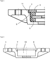
- a damper bearing according to the invention is shown in a top view in the fully assembled state.
- the damper bearing comprises a housing 1, which is intended to be mounted on the body of a motor vehicle via three flanges with through holes.
- a cavity In the center of the housing 1 there is a cavity in which a damping element 5 is received.
- the damping element 5 is fixed with a cover 3 in the cavity of the housing.
- the top of the lid is flush with the top of the housing.
- this version is not mandatory.
- the top of the cover can also protrude beyond the housing or be recessed into the cavity.
- the housing 1 and the cover 3 are made of plastic, in the example shown polyamide (PA 6.6) with a volume-related glass fiber content of 50%.
- the connection between the housing and the cover is made cohesively by a welding process that is based on a relative movement between the housing and the cover.
- Fig. 2 shows a longitudinal section through the damper bearing according to Fig. 1 .
- the damping element 5 is clamped between the housing base and the cover 3.
- the damping element 5 is designed as a hollow cylinder which has an annular groove in the center in the axial direction, in which an insert 15 is arranged. This insert 15 is used to attach the piston rod of a shock absorber to it.
- Fig. 3 shows an enlarged section of the representation of Fig. 2 .
- the outside diameter of the cover 3 is smaller than the inside diameter of the housing 1 in the area provided for receiving the cover 3.
- an annular gap 11 thus results between the cover 3 and the housing 1.
- the cover 3 has an annular groove on its underside, which faces the damping element 5.
- the area of the cover between the groove and its outer edge has a greater thickness than the inner area of the cover.
- the edge of the cover thus projects downward in the axial direction beyond the inner region of the cover.
- the lower ring surface of this edge represents the contact surface on the cover side, which is provided for welding to the housing.
- the housing 1 In the radial direction from the cavity in which the damping element 5 is arranged, the housing 1 initially has an annular web 7, which is followed by an annular groove. The bottom of this groove represents the housing-side contact surface 9, which is provided for welding to the cover.
- the 1 to 3 show the damper bearing in the assembled state.
- housing 1 and cover 3 were brought into contact at the abovementioned contact surfaces and then a relative movement was generated between the housing and cover.
- the relative movement causes an energy input in the form of friction in the contact surfaces, which leads to the plastic material melting at the contact surfaces and being welded integrally.
- the plastic material resulting from the melting remains in the area of the groove in the housing due to the shape of the cover and housing and is prevented by the web 7, which acts as a separating element, from coming into contact with the damping element 5. Impairment of the damping element 5 by the welding process is thereby minimized and, at best, completely avoided.
- the cover 3 is pressed in the direction of the housing base. The extent to which the cover penetrates into the cavity of the housing is measured. The welding process is continued until a predetermined pre-compression of the damping element 5 is reached.
- a longitudinal section through a housing 1 of a further example of a damper bearing according to the invention is shown.
- This damper bearing differs from the damper bearing according to Example 1 essentially in the shape of the contact surfaces 9 intended for welding.
- the contact surfaces of the housing and cover, which in FIG Fig. 4 are not shown, are conical in shape.
- the contact surface 9 of the housing is separated from the cavity 13 of the housing provided for receiving the damping element by an annular web 7.
- the housing and cover are brought into contact at the contact surfaces and then a relative movement is generated between the housing and cover.
- the plastic material on the conical contact surfaces melts as a result of the energy input and is bonded together.
- the area intended for fusing is larger due to the conical design. As in example 1, this will be Damping element protected from the melting material, since this remains in the annular groove that is formed between the web 7 and the contact surfaces.
Description
Die vorliegende Erfindung betrifft ein Dämpferlager umfassend ein hohles Gehäuse zur Aufnahme eines Dämpfungselements sowie einen Deckel zur Fixierung des Dämpfungselements in dem Gehäuse, wobei das Gehäuse und der Deckel aus Kunststoff gefertigt sind.The present invention relates to a damper bearing comprising a hollow housing for receiving a damping element and a cover for fixing the damping element in the housing, the housing and the cover being made of plastic.
Dämpferlager werden in Automobilen innerhalb des Fahrwerks verwendet und sind allgemein bekannt. Sie werden insbesondere in Kraftfahrzeugen als schwingungsdämpfende Bauteile eingesetzt. Dabei übernehmen sie die Anbindung des Stoßdämpfers an die Karosserie und/oder an Fahrwerkskomponenten. Durch eine solche elastische Ankopplung werden Schwingungen isoliert, die von der Fahrbahn hervorgerufen und über Rad und Stoßdämpfer weitergeleitet werden, sowie Schwingungen, die vom Stoßdämpfer hervorgerufen werden. Die Ankopplung wird so gestaltet, dass kardanische Bewegungen des Stoßdämpfers ermöglicht werden und die Anforderungen an Kraft-Weg-Kennungen in axialer, radialer und kardanischer Richtung erfüllt werden. Axiale sowie radiale Kennungen beeinflussen in Abhängigkeit von der Fahrwerkskonzeption wesentlich das Fahrverhalten und müssen exakt abgestimmt werden. Das Zusammenspiel aus Stoßdämpfer und Dämpferlager beeinflusst entscheidend den Fahrkomfort, die Fahrsicherheit, die Wank- bzw. Nickabstützung sowie die Reduktion von Effekten des Radstuckerns und Karosseriezitterns.Damper bearings are used in automobiles within the chassis and are generally known. They are used in particular in motor vehicles as vibration-damping components. They take over the connection of the shock absorber to the body and / or chassis components. Such an elastic coupling isolates vibrations that are caused by the road and are transmitted via the wheel and shock absorber, as well as vibrations that are caused by the shock absorber. The coupling is designed in such a way that cardanic movements of the shock absorber are made possible and the requirements for force-displacement identifications in the axial, radial and cardanic directions are met. Depending on the chassis concept, axial and radial identifiers significantly influence driving behavior and must be precisely coordinated. The interaction of shock absorber and damper bearing has a decisive influence on driving comfort, driving safety, roll and pitch support as well as the reduction in the effects of wheel picking and body tremors.
Es sind unterschiedliche Arten von Dämpferlagern bekannt, sowohl im Hinblick auf eingesetzte Materialien als auch im Hinblick auf Herstellverfahren. Weit verbreitet sind Dämpferlager auf Basis von Aluminium-Druckguss, in die ein elastomeres Dämpfungselement eingelegt ist. Zur Herstellung wird meist das Dämpfungselement in ein hohlzylindrisches Gehäuse eingelegt und anschließend das Gehäuse mit einem Deckel verschlossen. Üblicherweise weist das Gehäuse einen Kragen auf, in dessen Innendurchmesser der Deckel hineingedrückt wird. Dabei ist der Kragen des Gehäuses höher als der Deckel. Der überstehende Bereich des Kragens wird nach dem Aufdrücken des Deckels durch Verrollen bzw. Bördeln umgelegt. Hierdurch wird der Deckel fest in seiner Position fixiert. Nachteilig an diesem bekannten Verfahren ist, dass durch das Verrollen der Kante des Gehäuses die Kräfte, die im Fahrbetrieb auftreten können, begrenzt sind. Die Festigkeit des Lagers ist also durch die Festigkeit des verrollten Randes limitiert. Zudem kann ein "Aufrollen" des Randes im Dauerbetrieb die Haltbarkeit des Lagers einschränken.Different types of damper bearings are known, both with regard to the materials used and with regard to manufacturing processes. Damper bearings based on die-cast aluminum, in which an elastomeric damping element is inserted, are widespread. For the manufacture, the damping element is usually placed in a hollow cylindrical housing and then the housing is closed with a cover. The housing usually has a collar, into the inner diameter of which the cover is pressed. The collar of the housing is higher than the lid. The protruding area of the collar is folded over after the cover is pressed on by rolling or flanging. As a result, the lid is firmly fixed in its position. A disadvantage of this known method is that the rolling of the edge of the housing limits the forces which can occur during driving. The strength of the bearing is therefore limited by the strength of the rolled edge. In addition, "rolling up" the edge during continuous operation can limit the durability of the bearing.
Als Alternative zur Befestigung des Deckels durch Verrollen oder Bördeln sind Dämpferlager bekannt, bei denen der Deckel mit dem Gehäuse anderweitig formschlüssig verbunden ist, beispielsweise in Form eines Bajonettverschlusses oder durch Verschrauben. Als weitere Alternative sind stoffschlüssige Verbindungen bekannt, zum Beispiel durch Verschweißen des Deckels mit dem Gehäuse. So beschreibt die Offenlegungsschrift
Häufig besteht die Anforderung, das Dämpfungselement vorkomprimiert in dem Dämpferlager anzuordnen, um bestimmte Dämpfungseigenschaften zu gewährleisten. Obwohl mit sämtlichen bekannten Verfahren eine Vorkompression des Dämpfungselements grundsätzlich möglich ist, ist - unter anderem aufgrund von Fertigungstoleranzen und verfahrensbedingten Einschränkungen - eine definierte Einstellung der Vorkompression nach wie vor schwierig und kaum exakt und reproduzierbar zu erreichen.There is often a requirement to arrange the damping element precompressed in the damper bearing in order to ensure certain damping properties. Although pre-compression of the damping element is fundamentally possible with all known methods, a defined setting of the pre-compression is still difficult and hardly exact and reproducible to achieve, inter alia due to manufacturing tolerances and process-related restrictions.
Es stellte sich die Aufgabe, Dämpferlager bereitzustellen, bei denen eine definierte Vorkompression des Dämpfungselements einstellbar ist und die dennoch einfach zu fertigen und kostengünstig in der Herstellung sind.The object was to provide damper bearings in which a defined pre-compression of the damping element can be set and which are nevertheless easy to manufacture and inexpensive to manufacture.
Diese Aufgabe wurde gelöst durch erfindungsgemäße Dämpferlager, wie sie in Anspruch 1 angegeben sind. Die abhängigen Ansprüche 2 bis 7 sind auf weitere vorteilhafte Ausbildungen der Erfindung gerichtet. Weiterhin wird diese Aufgabe gelöst durch ein Verfahren, wie es in den Ansprüchen 8 bis 10 angegeben ist.This object was achieved by damper bearings according to the invention, as specified in
Erfindungsgemäße Dämpferlager umfassen ein hohles Gehäuse zur Aufnahme eines Dämpfungselements sowie einen Deckel, der geeignet ist, das Dämpfungselement in dem Gehäuse zu fixieren. Gehäuse und Deckel sind aus Kunststoff gefertigt. Erfindungsgemäß ist die Verbindung zwischen Gehäuse und Deckel stoffschlüssig durch einen Schweißprozess hergestellt, der auf einer Relativbewegung zwischen Gehäuse und Deckel beruht, wobei das Orbitalschweißen angewendet wird.Damper bearings according to the invention comprise a hollow housing for receiving a damping element and a cover which is suitable for fixing the damping element in the housing. Housing and cover are made of plastic. According to the invention, the connection between the housing and the cover is made cohesively by a welding process which is based on a relative movement between the housing and the cover, orbital welding being used.
Die Verschweißung von Gehäuse und Deckel erfolgt an dafür vorgesehenen Berührungsflächen. In einer bevorzugten Ausgestaltung der Erfindung sind die zur stoffschlüssigen Verbindung vorgesehenen Berührungsflächen des Gehäuses und des Deckels rotationssymmetrisch gestaltet. Die Rotationssymmetrie legt eine Rotationsachse fest. Im Folgenden werden die Begriffe "radial" und "axial" in Bezug auf diese Rotationsachse verwendet.The housing and cover are welded at the contact surfaces provided. In a preferred embodiment of the invention, the contact surfaces of the housing and the cover provided for the integral connection are designed to be rotationally symmetrical. The rotational symmetry defines an axis of rotation. In the following, the terms "radial" and "axial" are used in relation to this axis of rotation.
Vorzugsweise sind die Berührungsflächen des Gehäuses und des Deckels bezüglich der Rotationsachse in radialer Richtung von der äußeren Oberfläche des Dämpfungselements beabstandet. Dadurch wird gewährleistet, dass die beim Verschweißen entstehende Kunststoffmasse der Schweißnaht nicht unmittelbar mit dem Dämpfungselement in Berührung kommt, was die Dämpfungseigenschaften negativ beeinflussen könnte. In einer Fortbildung dieser bevorzugten Ausgestaltung sind die Berührungsflächen zudem durch ein Trennelement von der äußeren Oberfläche des Dämpfungselements getrennt. Dabei kann das Trennelement den Abstand zwischen Dämpfungselement und Berührungsfläche vollständig oder teilweise ausfüllen.The contact surfaces of the housing and the cover are preferably spaced apart from the outer surface of the damping element with respect to the axis of rotation in the radial direction. This ensures that the plastic mass of the weld seam that occurs during welding does not come into direct contact with the damping element, which could have a negative effect on the damping properties. In a development of this preferred embodiment, the contact surfaces are also separated from the outer surface of the damping element by a separating element. The separating element can completely or partially fill the distance between the damping element and the contact surface.
Besonders bevorzugt ist das Trennelement als Nut oder Steg ausgebildet, insbesondere als ringförmige Nut oder ringförmiger Steg. Die Nut oder der Steg können durchgehend oder unterbrochen ausgebildet sein. In dieser Hinsicht ist der Begriff "ringförmig" nicht einschränkend zu verstehen. Auch der Begriff "Trennelement" in der Einzahl verwendet ist diesbezüglich nicht einschränkend zu lesen. Bei dieser Ausgestaltung ist die radiale und axiale Ausdehnung der Nut oder des Steges vorzugsweise so bemessen, dass die beim Verschweißen entstehende Kunststoffmasse der Schweißnaht zumindest teilweise, insbesondere aber vollständig in dem durch Berührungsflächen und Nut oder Steg festgelegten Volumen aufgenommen werden kann.The separating element is particularly preferably designed as a groove or web, in particular as an annular groove or annular web. The groove or the web can be continuous or interrupted. In this regard, the term "ring-shaped" is not restrictive understand. The term "separating element" used in the singular should not be read restrictively in this regard. In this embodiment, the radial and axial extent of the groove or of the web is preferably dimensioned such that the plastic mass of the weld seam that arises during welding can be at least partially, but in particular completely, absorbed in the volume defined by the contact surfaces and the groove or web.
Das Trennelement ist vorzugsweise integral mit dem Gehäuse und/oder dem Deckel verbunden. Es kann beispielsweise Bestandteil der Spritzgussform sein, mit der Gehäuse bzw. Deckel hergestellt werden.The separating element is preferably integrally connected to the housing and / or the cover. For example, it can be part of the injection mold with which the housing or cover are produced.
In einer weiterhin bevorzugten Variante des erfindungsgemäßen Dämpferlagers sind die Berührungsflächen des Gehäuses und des Deckels konisch geformt. Auch bei dieser Variante kann ein Abstand und/oder ein Trennelement wie oben beschrieben vorgesehen sein.In a further preferred variant of the damper bearing according to the invention, the contact surfaces of the housing and the cover are conically shaped. In this variant too, a distance and / or a separating element can be provided as described above.
Das Gehäuse und der Deckel können aus demselben oder aus unterschiedlichen Kunststoffen gefertigt sein. Voraussetzung ist lediglich, dass die jeweiligen Berührungsflächen aufgrund einer Relativbewegung eine stoffschlüssige Verbindung eingehen können, was beispielsweise bei Thermoplasten der Fall ist. Im Hinblick auf Materialeigenschaften wie Festigkeit und Steifigkeit sind faserverstärkte Kunststoffmaterialien bevorzugt. Besonders bevorzugt sind Gehäuse und Deckel auf Basis derselben Kunststoffmatrix hergestellt, wobei der Faseranteil im Gehäuse und im Deckel gleich oder unterschiedlich sein kann.The housing and the lid can be made of the same or different plastics. The only requirement is that the respective contact surfaces can form a cohesive connection due to a relative movement, which is the case, for example, with thermoplastics. With regard to material properties such as strength and rigidity, fiber-reinforced plastic materials are preferred. Housing and cover are particularly preferably produced on the basis of the same plastic matrix, it being possible for the fiber content in the housing and in the cover to be the same or different.
In einer vorteilhaften Ausgestaltung ist das Gehäuse und der Deckel auf der Basis von faserverstärktem Polyamid mit einem Faseranteil von mehr als 20%, bevorzugt mehr als 30%, besonders bevorzugt mehr als 40% gefertigt. Der Faseranteil ist volumenbezogen zu verstehen.In an advantageous embodiment, the housing and the cover are made on the basis of fiber-reinforced polyamide with a fiber content of more than 20%, preferably more than 30%, particularly preferably more than 40%. The fiber content is to be understood in terms of volume.
Das erfindungsgemäße Dämpferlager ist geeignet, mindestens ein Dämpfungselement in seinem Gehäuse aufzunehmen, das mit dem Deckel in dem Gehäuse fixiert werden kann. Das Dämpfungselement kann einteilig oder mehrteilig sein und auf bekannten Materialien wie Gummi oder Polyisocyanat-Polyadditionsprodukten basieren.The damper bearing according to the invention is suitable for accommodating at least one damping element in its housing, which can be fixed in the housing with the cover. The damping element can be in one part or in several parts and based on known materials such as rubber or polyisocyanate polyaddition products.
In einer bevorzugten Ausführungsform basiert das Dämpfungselement auf Elastomeren auf der Basis von zelligen Polyisocyanat-Polyadditionsprodukten, besonders bevorzugt auf der Basis von zelligen Polyurethanelastomeren, die Polyharnstoffstrukturen enthalten können. Zellig bedeutet, dass die Zellen bevorzugt einen Durchmesser von 0,01 mm bis 0,5 mm, besonders bevorzugt von 0,01 mm bis 0,15 mm aufweisen.In a preferred embodiment, the damping element is based on elastomers based on cellular polyisocyanate polyaddition products, particularly preferably based on cellular polyurethane elastomers, which may contain polyurea structures. Cellular means that the cells preferably have a diameter of 0.01 mm to 0.5 mm, particularly preferably of 0.01 mm to 0.15 mm.
Besonders bevorzugt haben die Polyisocyanat-Polyadditionsprodukte mindestens eine der folgenden Materialeigenschaften: eine Dichte nach DIN EN ISO 845 zwischen 270 und 900 kg/m3, eine Zugfestigkeit nach DIN EN ISO 1798 von ≥ 2,0 N/mm2, eine Bruchdehnung nach DIN EN ISO 1798 von ≥ 200 % oder eine Weiterreißfestigkeit nach DIN ISO 34-1 B (b) von ≥ 8 N/mm. In weiter bevorzugten Ausführungsformen besitzt ein Polyisocyanat-Polyadditionsprodukt zwei, weiter bevorzugt drei dieser Materialeigenschaften, besonders bevorzugte Ausführungsformen besitzen alle vier der genannten Materialeigenschaften.The polyisocyanate polyaddition products particularly preferably have at least one of the following material properties: a density according to DIN EN ISO 845 of between 270 and 900 kg / m3, a tensile strength according to DIN EN ISO 1798 of ≥ 2.0 N / mm2, an elongation at break according to DIN EN ISO 1798 of ≥ 200% or a tear resistance according to DIN ISO 34-1 B (b) of ≥ 8 N / mm. In further preferred embodiments, a polyisocyanate polyaddition product has two, more preferably three of these material properties, particularly preferred embodiments have all four of the material properties mentioned.
Elastomere auf der Basis von Polyisocyanat-Polyadditionsprodukten und ihre Herstellung sind allgemein bekannt und vielfältig beschreiben, beispielsweise in
In einer bevorzugten Ausführungsform der Erfindung ist das Gehäuse derart gestaltet, dass nach der Verschweißung mit dem Deckel die axiale Ausdehnung des Hohlraums des Gehäuses von 50 % bis 95 % der Höhe des Dämpfungselements beträgt, sodass das Dämpfungselement vorkomprimiert ist. Die Vorkompression wird vorzugsweise umso größer gewählt, je stärker das Dämpfungselement beim Einsatz im Fahrzeug in axialer Richtung belastet und damit bewegt wird. Dadurch wird gewährleistet, dass auch bei großer Belastung das Dämpfungselement in Kontakt mit der Innenseite des Gehäuses und/oder des Deckels bleibt.In a preferred embodiment of the invention, the housing is designed such that, after welding to the cover, the axial expansion of the cavity of the housing is from 50% to 95% of the height of the damping element, so that the damping element is pre-compressed. The pre-compression is preferably chosen to be greater the more the damping element is loaded in the axial direction when it is used in the vehicle and is thus moved. This ensures that the damping element remains in contact with the inside of the housing and / or the cover even under heavy loads.
In einer weiteren bevorzugten Ausführungsform umfasst das Dämpfungselement einen Einleger, der geeignet ist, eine Kolbenstange eines Stoßdämpfers daran zu befestigen. Der Einleger ist vorteilhaft aus Metall, beispielsweise Stahl oder Aluminium gefertigt. Er kann auch aus einem harten Kunststoff gefertigt sein, beispielsweise einem faserverstärkten Polyamid.In a further preferred embodiment, the damping element comprises an insert which is suitable for fastening a piston rod of a shock absorber thereon. The insert is advantageously made of metal, for example steel or aluminum. It can also be made of a hard plastic, for example a fiber-reinforced polyamide.
Das erfindungsgemäße Dämpferlager wird vorteilhaft als Axiallager innerhalb des Fahrwerks eines Kraftfahrzeugs eingesetzt. In diesem Fall ist an dem Einleger vorzugsweise die Kolbenstange eines Stoßdämpfers befestigt.The damper bearing according to the invention is advantageously used as a thrust bearing within the chassis of a motor vehicle. In this case, the piston rod of a shock absorber is preferably attached to the insert.
Ein weiterer Gegenstand der Erfindung ist ein Verfahren zur Herstellung eines Dämpferlagers, das ein hohles Gehäuse zur Aufnahme eines Dämpfungselements sowie einen Deckel zur Fixierung des Dämpfungselements in dem Gehäuse umfasst, wobei das Gehäuse und der Deckel aus Kunststoff gefertigt sind. Bei dem erfindungsgemäßen Verfahren werden zunächst Gehäuse und Deckel an dazu vorgesehenen Berührungsflächen in Kontakt gebracht. Anschließend wird eine Relativbewegung zwischen Gehäuse und Deckel erzeugt, die aufgrund des Energieeintrages in die Berührungsflächen dazu führt, dass Gehäuse und Deckel stoffschlüssig verschweißen, wobei das Orbitalschweißen angewendet wird.Another object of the invention is a method for producing a damper bearing, which comprises a hollow housing for receiving a damping element and a cover for fixing the damping element in the housing, the housing and the cover being made of plastic. In the method according to the invention, the housing and cover are first brought into contact at the contact surfaces provided for this purpose. Subsequently, a relative movement between the housing and the cover is generated which, due to the energy input into the contact surfaces, leads to the housing and the cover being welded integrally, with orbital welding being used.
In Abhängigkeit der Bauteilgeometrie, insbesondere der in Kontakt zu bringenden Berührungsflächen, sind unterschiedliche Schweißverfahren anwendbar, insbesondere Reibschweißverfahren. Während bei ebenen Berührungsflächen auch ein lineares Reibschweißen in Betracht kommt, sind bei rotationssymmetrischen Berührungsflächen beispielsweise Verfahren des rotativen Reibschweißens oder rotativ oszillierenden Reibschweißens anwendbar. Erfindungsgemäß ist jedoch Orbitalschweißen vorgesehen.Depending on the component geometry, in particular the contact surfaces to be brought into contact, different welding methods can be used, in particular friction welding methods. While linear friction welding is also possible with flat contact surfaces, methods of rotary friction welding or rotationally oscillating friction welding can be used for rotationally symmetrical contact surfaces, for example. According to the invention, however, orbital welding is provided.
In einer anderen bevorzugten Form wird das oszillierende Reibschweißen, bevorzugt das linear oszillierende Reibschweißen, oder erfindungsgemäß das Orbitalschweißen angewendet. Dabei haben diese Schweißverfahren den Vorteil auch bei nicht rotationssymmetrischen Geometrien der zu verschweißenden Flächen angewendet werden zu können.In another preferred form, oscillating friction welding, preferably linear oscillating friction welding, or, according to the invention, orbital welding is used. Here these welding processes have the advantage of being able to be used even for non-rotationally symmetrical geometries of the surfaces to be welded.
Bevorzugt ist ein Orbitalschweißen, wie es in der ISO 15620 ausgeführt wird. Je nach Ausführung der Bauteile wird entweder das Single Orbitalschweißen angewendet, bei dem nur ein Bauteil schwingt, oder es wird das Multi-Orbitalreibschweißen angewendet, bei dem beide zu verschweißende Bauteile schwingen. Das Orbitalschweißen hat den Vorteil, dass die zu verbindenden Bauteile nicht rotationssymmetrisch sein müssen. Bei dem Orbitalschweißen bewegen sich die Achsen der zu verschweißenden Fläche in derselben Ebene.Orbital welding, as is carried out in ISO 15620, is preferred. Depending on the design of the components, either single orbital welding, in which only one component vibrates, or multi-orbital friction welding, in which both components to be welded vibrate, is used. Orbital welding has the advantage that the components to be connected do not have to be rotationally symmetrical. With orbital welding, the axes of the surface to be welded move in the same plane.
Besonders bevorzugt wird bei rotationssymmetrischen Berührungsflächen das Orbitalschweißen angewendet.Orbital welding is particularly preferably used for rotationally symmetrical contact surfaces.
Es wird das oben beschriebene Orbitalschweißen angewendet. Diese hat insbesondere bei faserverstärkten Bauteilen den Vorteil, dass die Fasern einen geringeren Faserorientierungsgrad aufweisen, wodurch es zu einer besseren Verschweißung kommt.The orbital welding described above is used. In the case of fiber-reinforced components in particular, this has the advantage that the fibers have a lower degree of fiber orientation, which leads to better welding.
Da üblicherweise das Dämpfungselement vorgespannt werden soll, findet während des Verschweißens auch ein Kontakt zwischen Deckel und Dämpfungselement statt. Um die Wahrscheinlichkeit einer möglichen thermischen oder mechanischen Schädigung des Dämpfungselements während des Verschweißens zu verringern, sind Schweißverfahren besonders bevorzugt, die nur eine geringe Einwirkung auf das Dämpfungselement verursachen, beispielsweise das Orbitalschweißen.Since the damping element is usually to be preloaded, there is also contact between the cover and the damping element during welding. In order to reduce the likelihood of possible thermal or mechanical damage to the damping element during welding, welding methods are particularly preferred which only have a slight effect on the damping element, for example orbital welding.
Dabei wird die Relativbewegung der zu verschweißenden Bauteile so eingestellt, dass diese zwar miteinander verschweißen, das Dämpfungselement aber auf Grund seiner Elastizität nur so geringe Bewegungen erfährt, dass sich das thermoplastische Bauteil nur so gering erwärmt, dass es nicht zu einer Vebindung kommt. Dabei wird die thermische und mechanische Schädigung des Dämpfungselements reduziert, idealerweise vollständig unterbunden.The relative movement of the components to be welded is set so that they weld together, but due to its elasticity the damping element only experiences so little movement that the thermoplastic component heats up only so little that there is no connection. The thermal and mechanical damage to the damping element is reduced, ideally completely prevented.
In einer bevorzugten Ausgestaltung des erfindungsgemäßen Verfahrens wird während der Relativbewegung die Eindringtiefe des Deckels in den Hohlraum des Gehäuses messtechnisch erfasst. Bei einer Schweißvorrichtung, die das Gehäuse und den Deckel in separaten Werkzeugen hält, um die Relativbewegung durchzuführen, kann die messtechnische Erfassung beispielsweise dadurch erfolgen, dass eine Änderung des Abstands der Werkzeuge zueinander (Wegänderung) oder eine Änderung der aufzuwendenden Kräfte erfasst wird.In a preferred embodiment of the method according to the invention, the depth of penetration of the cover into the cavity of the housing is measured during the relative movement. In the case of a welding device which holds the housing and the cover in separate tools in order to carry out the relative movement, the measurement can be carried out, for example, by detecting a change in the distance between the tools (change in path) or a change in the forces to be applied.
Besonders bevorzugt wird die messtechnisch bestimmte Veränderung verwendet, um eine vorgegebene Kompression des Dämpfungselements einzustellen. Dies kann beispielsweise dadurch realisiert werden, dass die Änderung des Abstands zweier Werkzeuge zueinander erfasst wird und die während der Relativbewegung aufzubringenden Anpresskräfte der Werkzeuge derart angepasst werden, dass am Ende des Schweißprozesses eine vorbestimmte Eindringtiefe des Deckels in den Hohlraum des Gehäuses erreicht ist. Für die software- und/oder hardwaretechnische Umsetzung kann auf bekannte Verfahren zurückgegriffen werden.The change determined by measurement technology is particularly preferably used in order to set a predetermined compression of the damping element. This can be achieved, for example, by detecting the change in the distance between two tools and the pressure forces of the tools to be applied during the relative movement be adapted such that a predetermined depth of penetration of the cover into the cavity of the housing is reached at the end of the welding process. Known methods can be used for the software and / or hardware implementation.
Gegenüber Dämpferlagern, wie sie aus dem Stand der Technik bekannt sind, weisen erfindungsgemäße Dämpferlager insbesondere den Vorteil auf, dass aufgrund der variablen Einschweißtiefe des Deckels die Vorkompression des Dämpfungselements auf einen definierten Wert eingestellt werden kann. Darüber hinaus gewährleisten die gewählten Verfahren auch bei höheren Vorspannung, dass es zu keiner Verbindung zwischen dem Dämpfungselement und den Anbauteilen kommt. Das erfindungsgemäße Verfahren eignet sich auch zur Serienfertigung, sodass eine einfache und kostengünstige Herstellung der Dämpferlager in reproduzierbar hoher Qualität möglich ist.Compared to damper bearings, as are known from the prior art, damper bearings according to the invention have the particular advantage that, due to the variable welding depth of the cover, the pre-compression of the damping element can be set to a defined value. In addition, the selected methods ensure that there is no connection between the damping element and the add-on parts, even with higher preload. The method according to the invention is also suitable for series production, so that simple and inexpensive manufacture of the damper bearings in reproducibly high quality is possible.
In
Das Gehäuse 1 und der Deckel 3 sind aus Kunststoff gefertigt, in dem dargestellten Beispiel aus Polyamid (PA 6.6) mit einem volumenbezogenen Glasfaseranteil von 50%. Die Verbindung zwischen Gehäuse und Deckel ist stoffschlüssig durch einen Schweißprozess hergestellt, der auf einer Relativbewegung zwischen Gehäuse und Deckel beruht.The
Der Bereich des Deckels zwischen der Nut und seinem äußeren Rand hat eine größere Dicke als der innere Bereich des Deckels. Somit ragt der Rand des Deckels in axialer Richtung nach unten über den inneren Bereich des Deckels hinaus. Die untere Ringfläche dieses Randes stellt die deckelseitige Berührungsfläche dar, die zum Verschweißen mit dem Gehäuse vorgesehen ist.The area of the cover between the groove and its outer edge has a greater thickness than the inner area of the cover. The edge of the cover thus projects downward in the axial direction beyond the inner region of the cover. The lower ring surface of this edge represents the contact surface on the cover side, which is provided for welding to the housing.
Das Gehäuse 1 weist in radialer Richtung vom Hohlraum, in dem das Dämpfungselement 5 angeordnet ist, ausgehend nach außen zunächst einen ringförmigen Steg 7 auf, dem eine ringförmige Nut folgt. Der Boden dieser Nut stellt die gehäuseseitige Berührungsfläche 9 dar, die zum Verschweißen mit dem Deckel vorgesehen ist.In the radial direction from the cavity in which the damping
Die
Während des Schweißprozesses wird der Deckel 3 in Richtung des Gehäusebodens gedrückt. Dabei wird messtechnisch erfasst, wie weit der Deckel in den Hohlraum des Gehäuses eindringt. Der Schweißprozess wird solange fortgesetzt, bis eine vorab festgelegte Vorkompression des Dämpfungselements 5 erreicht ist.During the welding process, the
In
Zum Verschweißen werden Gehäuse und Deckel an den Berührungsflächen in Kontakt gebracht und anschließend eine Relativbewegung zwischen Gehäuse und Deckel erzeugt. Das Kunststoffmaterial an den konischen Berührungsflächen schmilzt aufgrund des Energieeintrages und verbindet sich stoffschlüssig. Im Vergleich zu Beispiel 1 ist die zum Verschmelzen vorgesehene Fläche aufgrund der konischen Gestaltung größer. Ebenso wie in Beispiel 1 wird das Dämpfungselement vor dem aufschmelzenden Material geschützt, da dieses in der Ringnut verbleibt, die zwischen dem Steg 7 und den Berührungsflächen gebildet wird.For welding, the housing and cover are brought into contact at the contact surfaces and then a relative movement is generated between the housing and cover. The plastic material on the conical contact surfaces melts as a result of the energy input and is bonded together. In comparison to Example 1, the area intended for fusing is larger due to the conical design. As in example 1, this will be Damping element protected from the melting material, since this remains in the annular groove that is formed between the
Claims (10)
- A damper bearing comprising a hollow housing (1) for receiving a damping element (5) and a cover (3) for fixing the damping element (5) in the housing (1), wherein the housing (1) and the cover (3) are manufactured from plastic, wherein the connection between the housing (1) and the cover (3) is produced integrally by a welding process, which is based on a relative movement between the housing (1) and the cover (3), wherein orbital welding is used.
- The damper bearing according to claim 1, wherein the contact surfaces of the housing (1) and of the cover (3) which are provided for the integral connection are of rotationally symmetrical design.
- The damper bearing according to either of the preceding claims, wherein the contact surfaces of the housing (1) and of the cover (3) are spaced apart from the outer surface of the damping element (5) in a radial direction relative to the axis of rotation and are separated by a separating element (7).
- The damper bearing according to claim 3, wherein the separating element (7) is designed as a groove or web.
- The damper bearing according to one of the preceding claims, wherein the contact surfaces of the housing (1) and of the cover (3) are conically shaped.
- The damper bearing according to one of the preceding claims, wherein the housing (1) and the cover (3) are manufactured on the basis of fiber-reinforced polyamide with a fiber content of more than 20%, preferably more than 30%, particularly preferably more than 40%.
- The damper bearing according to one of the preceding claims, wherein the damping element is based on a cellular polyisocyanate polyaddition product.
- A method for producing a damper bearing, which comprises a hollow housing (1) for receiving a damping element (5) and a cover (3) for fixing the damping element (5) in the housing (1), wherein the housing (1) and the cover (3) are manufactured from plastic, wherein the housing and the cover are brought into contact at contact surfaces provided for this purpose, and a relative movement between the housing and the cover is then generated, which causes the housing and the cover to be integrally welded as a result of the energy input into the contact surfaces, wherein orbital welding is used.
- The method according to claim 8, wherein the penetration depth of the cover (3) into the cavity of the housing (1) is detected metrologically during the relative movement.
- The method according to claim 9, wherein the metrologically determined change is used to set a specified compression of the damping element (5).
Applications Claiming Priority (2)
| Application Number | Priority Date | Filing Date | Title |
|---|---|---|---|
| DE102015217605 | 2015-09-15 | ||
| PCT/EP2016/071014 WO2017045978A1 (en) | 2015-09-15 | 2016-09-07 | Damper bearing comprising a housing and cover |
Publications (2)
| Publication Number | Publication Date |
|---|---|
| EP3350472A1 EP3350472A1 (en) | 2018-07-25 |
| EP3350472B1 true EP3350472B1 (en) | 2020-04-22 |
Family
ID=56896540
Family Applications (1)
| Application Number | Title | Priority Date | Filing Date |
|---|---|---|---|
| EP16763502.8A Active EP3350472B1 (en) | 2015-09-15 | 2016-09-07 | Damper bearing comprising a housing and cover |
Country Status (4)
| Country | Link |
|---|---|
| US (1) | US20180266509A1 (en) |
| EP (1) | EP3350472B1 (en) |
| CN (1) | CN108027001B (en) |
| WO (1) | WO2017045978A1 (en) |
Families Citing this family (4)
| Publication number | Priority date | Publication date | Assignee | Title |
|---|---|---|---|---|
| FR3069898B1 (en) * | 2017-08-02 | 2019-12-27 | Sogefi Suspensions | BEARING FOR STABILIZER BAR WITH PLYWOOD |
| DE102018211118A1 (en) * | 2018-07-05 | 2020-01-09 | Thyssenkrupp Bilstein Gmbh | Damper device, method for producing a damper device |
| KR20200023779A (en) * | 2018-08-27 | 2020-03-06 | 주식회사 만도 | Electric Control Unit |
| BE1027881B1 (en) * | 2019-12-18 | 2021-07-27 | Atlas Copco Airpower Nv | Compressor device and device equipped with a bearing damper |
Family Cites Families (15)
| Publication number | Priority date | Publication date | Assignee | Title |
|---|---|---|---|---|
| US4350777A (en) | 1980-03-28 | 1982-09-21 | Bayer Aktiengesellschaft | Impermeable molded articles of cellular polyurethane elastomers produced with organofunctional polysiloxane-derivatives and their use as spring elements |
| DE3113690A1 (en) | 1981-04-04 | 1982-10-28 | Elastogran GmbH, 2844 Lemförde | "METHOD FOR PRODUCING CLOSED-CELL POLYURETHANE MOLDED PARTS WITH A COMPRESSED EDGE ZONE" |
| DE3621040A1 (en) | 1986-06-24 | 1988-01-07 | Bayer Ag | METHOD FOR THE PRODUCTION AND POLYSILOXANE IONOMERS, POLYSILOXAN IONOMERS AND THE USE THEREOF FOR THE PRODUCTION OF CELLED POLYURETHANE ELASTOMERS |
| DE4321874A1 (en) | 1993-07-01 | 1995-01-12 | Ver Foerderung Inst Kunststoff | Process and device for the open-loop and closed-loop control of process parameters in ultrasonic welding |
| DE19548771A1 (en) | 1995-12-23 | 1997-06-26 | Basf Ag | Microcellular polyurethane elastomer containing urea groups |
| DE19548770A1 (en) | 1995-12-23 | 1997-06-26 | Basf Ag | Microcellular polyurethane elastomer containing urea groups |
| JP3777262B2 (en) * | 1998-12-16 | 2006-05-24 | 日信工業株式会社 | Plastic parts |
| WO2000063279A1 (en) | 1999-04-15 | 2000-10-26 | Basf Aktiengesellschaft | Cellular polyisocyanate-polyaddition products |
| DE19919573A1 (en) * | 1999-04-29 | 2000-11-02 | Wolf Woco & Co Franz J | Torsion bar shoulder bearings |
| DE10227978B4 (en) * | 2002-06-22 | 2005-12-29 | Zf Boge Elastmetall Gmbh | Dämfungselement |
| DE10335956A1 (en) | 2003-08-04 | 2005-02-24 | Basf Ag | Spring unit for motor vehicles comprises a top cover joined to the vehicle bodywork, and a bottom cover which is joined to the top cover by shape, material bonds and/or forces |
| DE102007003207A1 (en) * | 2006-02-24 | 2007-08-30 | Basf Ag | Damper mounting assembly connected to vehicle shock absorber, comprises inlay in seat located in radial and axial directions between cover welded to casing |
| EP1878560A1 (en) * | 2006-07-12 | 2008-01-16 | Basf Aktiengesellschaft | Plastic-rubber composite and method of manufacturing thereof |
| DE102012001299A1 (en) | 2012-01-25 | 2013-07-25 | Basf Se | Damper bearing for use as vibration damping component in chassis frame of motor vehicle, has hollow housing for receiving damping element, where inner surfaces of housing base and cover have contours formed by elevations and depressions |
| DE102012002433B4 (en) * | 2012-02-08 | 2019-11-07 | Volkswagen Aktiengesellschaft | Damper bearing for a piston rod of a vibration damper and motor vehicle with such a damper bearing |
-
2016
- 2016-09-07 WO PCT/EP2016/071014 patent/WO2017045978A1/en active Application Filing
- 2016-09-07 EP EP16763502.8A patent/EP3350472B1/en active Active
- 2016-09-07 US US15/758,432 patent/US20180266509A1/en not_active Abandoned
- 2016-09-07 CN CN201680053728.8A patent/CN108027001B/en active Active
Non-Patent Citations (1)
| Title |
|---|
| None * |
Also Published As
| Publication number | Publication date |
|---|---|
| EP3350472A1 (en) | 2018-07-25 |
| CN108027001A (en) | 2018-05-11 |
| WO2017045978A1 (en) | 2017-03-23 |
| US20180266509A1 (en) | 2018-09-20 |
| CN108027001B (en) | 2021-05-11 |
Similar Documents
| Publication | Publication Date | Title |
|---|---|---|
| EP2697084B1 (en) | Bearing arrangement for a spring of a vehicle chassis | |
| EP3350472B1 (en) | Damper bearing comprising a housing and cover | |
| DE102006016060B4 (en) | Radial joint and method for producing such a radial joint for a motor vehicle | |
| EP3464929B1 (en) | Spring element for a vehicle shock absorber, as well as vehicle shock absorber and use of this spring element | |
| DE102018221463B4 (en) | Air spring assembly with a support ring made of plastic material and method of attaching a bellows to a top cap with such a support ring | |
| DE10335956A1 (en) | Spring unit for motor vehicles comprises a top cover joined to the vehicle bodywork, and a bottom cover which is joined to the top cover by shape, material bonds and/or forces | |
| DE102018216993A1 (en) | Air spring with thermoset connector | |
| EP1516133A1 (en) | Circular mount | |
| DE102013217321A1 (en) | End parts and gas spring assemblies with the same | |
| DE102009022841B4 (en) | Elastic strut head bearing for a motor vehicle and method for adjusting a compression preload in an elastic ring body of the shock absorber head bearing | |
| DE102007003207A1 (en) | Damper mounting assembly connected to vehicle shock absorber, comprises inlay in seat located in radial and axial directions between cover welded to casing | |
| DE102012018883B4 (en) | additional spring | |
| DE102017203537B3 (en) | Method for producing a leaf spring, and leaf spring and suspension | |
| DE102006021816B3 (en) | Sliding device for moving vehicle parts e.g. roof comprises a sliding body formed as a foam body and a sliding wall | |
| DE102016219474B4 (en) | Actuator and method for producing an actuator | |
| EP2646706B1 (en) | Shock-absorbing bearing comprising a profiled insert | |
| EP1878560A1 (en) | Plastic-rubber composite and method of manufacturing thereof | |
| DE10250436B3 (en) | Bearing for piston rod comprises bearing mounting and counter-bearing with flange whose upper and lower surfaces are fitted with bearing components | |
| EP3541643A1 (en) | Absorber mount and method for producing an absorber mount | |
| DE102021118280B4 (en) | Elastomeric metal bearing and process for its production | |
| DE102018202353A1 (en) | Pre-product with a load-bearing component and method for adapting said load-bearing component to a load request | |
| DE19742955A1 (en) | Bearing member e.g. for connecting two vehicle components | |
| DE10309202A1 (en) | spring construction | |
| DE102004002369B4 (en) | Spring construction containing positively fixed round bearings, in particular for automobile chassis | |
| DE202021103783U1 (en) | Elastomer-Metal Bearing |
Legal Events
| Date | Code | Title | Description |
|---|---|---|---|
| STAA | Information on the status of an ep patent application or granted ep patent |
Free format text: STATUS: THE INTERNATIONAL PUBLICATION HAS BEEN MADE |
|
| PUAI | Public reference made under article 153(3) epc to a published international application that has entered the european phase |
Free format text: ORIGINAL CODE: 0009012 |
|
| STAA | Information on the status of an ep patent application or granted ep patent |
Free format text: STATUS: REQUEST FOR EXAMINATION WAS MADE |
|
| 17P | Request for examination filed |
Effective date: 20180416 |
|
| AK | Designated contracting states |
Kind code of ref document: A1 Designated state(s): AL AT BE BG CH CY CZ DE DK EE ES FI FR GB GR HR HU IE IS IT LI LT LU LV MC MK MT NL NO PL PT RO RS SE SI SK SM TR |
|
| AX | Request for extension of the european patent |
Extension state: BA ME |
|
| DAV | Request for validation of the european patent (deleted) | ||
| DAX | Request for extension of the european patent (deleted) | ||
| GRAP | Despatch of communication of intention to grant a patent |
Free format text: ORIGINAL CODE: EPIDOSNIGR1 |
|
| STAA | Information on the status of an ep patent application or granted ep patent |
Free format text: STATUS: GRANT OF PATENT IS INTENDED |
|
| INTG | Intention to grant announced |
Effective date: 20191204 |
|
| GRAS | Grant fee paid |
Free format text: ORIGINAL CODE: EPIDOSNIGR3 |
|
| GRAA | (expected) grant |
Free format text: ORIGINAL CODE: 0009210 |
|
| STAA | Information on the status of an ep patent application or granted ep patent |
Free format text: STATUS: THE PATENT HAS BEEN GRANTED |
|
| AK | Designated contracting states |
Kind code of ref document: B1 Designated state(s): AL AT BE BG CH CY CZ DE DK EE ES FI FR GB GR HR HU IE IS IT LI LT LU LV MC MK MT NL NO PL PT RO RS SE SI SK SM TR |
|
| REG | Reference to a national code |
Ref country code: CH Ref legal event code: EP |
|
| REG | Reference to a national code |
Ref country code: IE Ref legal event code: FG4D Free format text: LANGUAGE OF EP DOCUMENT: GERMAN |
|
| REG | Reference to a national code |
Ref country code: DE Ref legal event code: R096 Ref document number: 502016009672 Country of ref document: DE |
|
| REG | Reference to a national code |
Ref country code: AT Ref legal event code: REF Ref document number: 1260528 Country of ref document: AT Kind code of ref document: T Effective date: 20200515 |
|
| REG | Reference to a national code |
Ref country code: LT Ref legal event code: MG4D |
|
| REG | Reference to a national code |
Ref country code: NL Ref legal event code: MP Effective date: 20200422 |
|
| PG25 | Lapsed in a contracting state [announced via postgrant information from national office to epo] |
Ref country code: PT Free format text: LAPSE BECAUSE OF FAILURE TO SUBMIT A TRANSLATION OF THE DESCRIPTION OR TO PAY THE FEE WITHIN THE PRESCRIBED TIME-LIMIT Effective date: 20200824 Ref country code: NO Free format text: LAPSE BECAUSE OF FAILURE TO SUBMIT A TRANSLATION OF THE DESCRIPTION OR TO PAY THE FEE WITHIN THE PRESCRIBED TIME-LIMIT Effective date: 20200722 Ref country code: GR Free format text: LAPSE BECAUSE OF FAILURE TO SUBMIT A TRANSLATION OF THE DESCRIPTION OR TO PAY THE FEE WITHIN THE PRESCRIBED TIME-LIMIT Effective date: 20200723 Ref country code: NL Free format text: LAPSE BECAUSE OF FAILURE TO SUBMIT A TRANSLATION OF THE DESCRIPTION OR TO PAY THE FEE WITHIN THE PRESCRIBED TIME-LIMIT Effective date: 20200422 Ref country code: LT Free format text: LAPSE BECAUSE OF FAILURE TO SUBMIT A TRANSLATION OF THE DESCRIPTION OR TO PAY THE FEE WITHIN THE PRESCRIBED TIME-LIMIT Effective date: 20200422 Ref country code: IS Free format text: LAPSE BECAUSE OF FAILURE TO SUBMIT A TRANSLATION OF THE DESCRIPTION OR TO PAY THE FEE WITHIN THE PRESCRIBED TIME-LIMIT Effective date: 20200822 Ref country code: SE Free format text: LAPSE BECAUSE OF FAILURE TO SUBMIT A TRANSLATION OF THE DESCRIPTION OR TO PAY THE FEE WITHIN THE PRESCRIBED TIME-LIMIT Effective date: 20200422 Ref country code: FI Free format text: LAPSE BECAUSE OF FAILURE TO SUBMIT A TRANSLATION OF THE DESCRIPTION OR TO PAY THE FEE WITHIN THE PRESCRIBED TIME-LIMIT Effective date: 20200422 |
|
| PG25 | Lapsed in a contracting state [announced via postgrant information from national office to epo] |
Ref country code: LV Free format text: LAPSE BECAUSE OF FAILURE TO SUBMIT A TRANSLATION OF THE DESCRIPTION OR TO PAY THE FEE WITHIN THE PRESCRIBED TIME-LIMIT Effective date: 20200422 Ref country code: HR Free format text: LAPSE BECAUSE OF FAILURE TO SUBMIT A TRANSLATION OF THE DESCRIPTION OR TO PAY THE FEE WITHIN THE PRESCRIBED TIME-LIMIT Effective date: 20200422 Ref country code: BG Free format text: LAPSE BECAUSE OF FAILURE TO SUBMIT A TRANSLATION OF THE DESCRIPTION OR TO PAY THE FEE WITHIN THE PRESCRIBED TIME-LIMIT Effective date: 20200722 Ref country code: RS Free format text: LAPSE BECAUSE OF FAILURE TO SUBMIT A TRANSLATION OF THE DESCRIPTION OR TO PAY THE FEE WITHIN THE PRESCRIBED TIME-LIMIT Effective date: 20200422 |
|
| PG25 | Lapsed in a contracting state [announced via postgrant information from national office to epo] |
Ref country code: AL Free format text: LAPSE BECAUSE OF FAILURE TO SUBMIT A TRANSLATION OF THE DESCRIPTION OR TO PAY THE FEE WITHIN THE PRESCRIBED TIME-LIMIT Effective date: 20200422 |
|
| REG | Reference to a national code |
Ref country code: DE Ref legal event code: R097 Ref document number: 502016009672 Country of ref document: DE |
|
| PG25 | Lapsed in a contracting state [announced via postgrant information from national office to epo] |
Ref country code: CZ Free format text: LAPSE BECAUSE OF FAILURE TO SUBMIT A TRANSLATION OF THE DESCRIPTION OR TO PAY THE FEE WITHIN THE PRESCRIBED TIME-LIMIT Effective date: 20200422 Ref country code: RO Free format text: LAPSE BECAUSE OF FAILURE TO SUBMIT A TRANSLATION OF THE DESCRIPTION OR TO PAY THE FEE WITHIN THE PRESCRIBED TIME-LIMIT Effective date: 20200422 Ref country code: ES Free format text: LAPSE BECAUSE OF FAILURE TO SUBMIT A TRANSLATION OF THE DESCRIPTION OR TO PAY THE FEE WITHIN THE PRESCRIBED TIME-LIMIT Effective date: 20200422 Ref country code: SM Free format text: LAPSE BECAUSE OF FAILURE TO SUBMIT A TRANSLATION OF THE DESCRIPTION OR TO PAY THE FEE WITHIN THE PRESCRIBED TIME-LIMIT Effective date: 20200422 Ref country code: EE Free format text: LAPSE BECAUSE OF FAILURE TO SUBMIT A TRANSLATION OF THE DESCRIPTION OR TO PAY THE FEE WITHIN THE PRESCRIBED TIME-LIMIT Effective date: 20200422 Ref country code: IT Free format text: LAPSE BECAUSE OF FAILURE TO SUBMIT A TRANSLATION OF THE DESCRIPTION OR TO PAY THE FEE WITHIN THE PRESCRIBED TIME-LIMIT Effective date: 20200422 Ref country code: DK Free format text: LAPSE BECAUSE OF FAILURE TO SUBMIT A TRANSLATION OF THE DESCRIPTION OR TO PAY THE FEE WITHIN THE PRESCRIBED TIME-LIMIT Effective date: 20200422 |
|
| PG25 | Lapsed in a contracting state [announced via postgrant information from national office to epo] |
Ref country code: SK Free format text: LAPSE BECAUSE OF FAILURE TO SUBMIT A TRANSLATION OF THE DESCRIPTION OR TO PAY THE FEE WITHIN THE PRESCRIBED TIME-LIMIT Effective date: 20200422 Ref country code: PL Free format text: LAPSE BECAUSE OF FAILURE TO SUBMIT A TRANSLATION OF THE DESCRIPTION OR TO PAY THE FEE WITHIN THE PRESCRIBED TIME-LIMIT Effective date: 20200422 |
|
| PLBE | No opposition filed within time limit |
Free format text: ORIGINAL CODE: 0009261 |
|
| STAA | Information on the status of an ep patent application or granted ep patent |
Free format text: STATUS: NO OPPOSITION FILED WITHIN TIME LIMIT |
|
| 26N | No opposition filed |
Effective date: 20210125 |
|
| REG | Reference to a national code |
Ref country code: CH Ref legal event code: PL |
|
| GBPC | Gb: european patent ceased through non-payment of renewal fee |
Effective date: 20200907 |
|
| PG25 | Lapsed in a contracting state [announced via postgrant information from national office to epo] |
Ref country code: SI Free format text: LAPSE BECAUSE OF FAILURE TO SUBMIT A TRANSLATION OF THE DESCRIPTION OR TO PAY THE FEE WITHIN THE PRESCRIBED TIME-LIMIT Effective date: 20200422 |
|
| REG | Reference to a national code |
Ref country code: BE Ref legal event code: MM Effective date: 20200930 |
|
| PG25 | Lapsed in a contracting state [announced via postgrant information from national office to epo] |
Ref country code: LU Free format text: LAPSE BECAUSE OF NON-PAYMENT OF DUE FEES Effective date: 20200907 |
|
| PG25 | Lapsed in a contracting state [announced via postgrant information from national office to epo] |
Ref country code: FR Free format text: LAPSE BECAUSE OF NON-PAYMENT OF DUE FEES Effective date: 20200930 |
|
| PG25 | Lapsed in a contracting state [announced via postgrant information from national office to epo] |
Ref country code: IE Free format text: LAPSE BECAUSE OF NON-PAYMENT OF DUE FEES Effective date: 20200907 Ref country code: LI Free format text: LAPSE BECAUSE OF NON-PAYMENT OF DUE FEES Effective date: 20200930 Ref country code: GB Free format text: LAPSE BECAUSE OF NON-PAYMENT OF DUE FEES Effective date: 20200907 Ref country code: BE Free format text: LAPSE BECAUSE OF NON-PAYMENT OF DUE FEES Effective date: 20200930 Ref country code: CH Free format text: LAPSE BECAUSE OF NON-PAYMENT OF DUE FEES Effective date: 20200930 |
|
| PG25 | Lapsed in a contracting state [announced via postgrant information from national office to epo] |
Ref country code: TR Free format text: LAPSE BECAUSE OF FAILURE TO SUBMIT A TRANSLATION OF THE DESCRIPTION OR TO PAY THE FEE WITHIN THE PRESCRIBED TIME-LIMIT Effective date: 20200422 Ref country code: MT Free format text: LAPSE BECAUSE OF FAILURE TO SUBMIT A TRANSLATION OF THE DESCRIPTION OR TO PAY THE FEE WITHIN THE PRESCRIBED TIME-LIMIT Effective date: 20200422 Ref country code: CY Free format text: LAPSE BECAUSE OF FAILURE TO SUBMIT A TRANSLATION OF THE DESCRIPTION OR TO PAY THE FEE WITHIN THE PRESCRIBED TIME-LIMIT Effective date: 20200422 |
|
| PG25 | Lapsed in a contracting state [announced via postgrant information from national office to epo] |
Ref country code: MK Free format text: LAPSE BECAUSE OF FAILURE TO SUBMIT A TRANSLATION OF THE DESCRIPTION OR TO PAY THE FEE WITHIN THE PRESCRIBED TIME-LIMIT Effective date: 20200422 Ref country code: MC Free format text: LAPSE BECAUSE OF FAILURE TO SUBMIT A TRANSLATION OF THE DESCRIPTION OR TO PAY THE FEE WITHIN THE PRESCRIBED TIME-LIMIT Effective date: 20200422 |
|
| REG | Reference to a national code |
Ref country code: AT Ref legal event code: MM01 Ref document number: 1260528 Country of ref document: AT Kind code of ref document: T Effective date: 20210907 |
|
| PG25 | Lapsed in a contracting state [announced via postgrant information from national office to epo] |
Ref country code: AT Free format text: LAPSE BECAUSE OF NON-PAYMENT OF DUE FEES Effective date: 20210907 |
|
| PGFP | Annual fee paid to national office [announced via postgrant information from national office to epo] |
Ref country code: DE Payment date: 20230928 Year of fee payment: 8 |