EP3350440B1 - Système de revêtement de sol - Google Patents
Système de revêtement de sol Download PDFInfo
- Publication number
- EP3350440B1 EP3350440B1 EP16770313.1A EP16770313A EP3350440B1 EP 3350440 B1 EP3350440 B1 EP 3350440B1 EP 16770313 A EP16770313 A EP 16770313A EP 3350440 B1 EP3350440 B1 EP 3350440B1
- Authority
- EP
- European Patent Office
- Prior art keywords
- tile
- footstep
- communications device
- mobile communications
- tiles
- Prior art date
- Legal status (The legal status is an assumption and is not a legal conclusion. Google has not performed a legal analysis and makes no representation as to the accuracy of the status listed.)
- Active
Links
- 238000009408 flooring Methods 0.000 title description 54
- 230000033001 locomotion Effects 0.000 claims description 44
- 238000010295 mobile communication Methods 0.000 claims description 27
- 230000005540 biological transmission Effects 0.000 claims description 24
- 238000004891 communication Methods 0.000 claims description 13
- 238000000034 method Methods 0.000 claims description 10
- 238000012544 monitoring process Methods 0.000 claims description 4
- 230000000875 corresponding effect Effects 0.000 description 14
- 238000012545 processing Methods 0.000 description 14
- 230000005611 electricity Effects 0.000 description 12
- 239000000463 material Substances 0.000 description 10
- 238000007789 sealing Methods 0.000 description 7
- 239000007788 liquid Substances 0.000 description 4
- 230000001953 sensory effect Effects 0.000 description 4
- 238000006073 displacement reaction Methods 0.000 description 3
- 229920001971 elastomer Polymers 0.000 description 3
- 230000005484 gravity Effects 0.000 description 3
- 229920001084 poly(chloroprene) Polymers 0.000 description 3
- 239000012858 resilient material Substances 0.000 description 3
- 239000000919 ceramic Substances 0.000 description 2
- 230000000295 complement effect Effects 0.000 description 2
- 238000005259 measurement Methods 0.000 description 2
- 229920000784 Nomex Polymers 0.000 description 1
- 239000004743 Polypropylene Substances 0.000 description 1
- 229910000831 Steel Inorganic materials 0.000 description 1
- 241000826860 Trapezium Species 0.000 description 1
- 230000001133 acceleration Effects 0.000 description 1
- 230000001413 cellular effect Effects 0.000 description 1
- 239000004568 cement Substances 0.000 description 1
- 239000011093 chipboard Substances 0.000 description 1
- 239000002131 composite material Substances 0.000 description 1
- 230000002596 correlated effect Effects 0.000 description 1
- 230000001186 cumulative effect Effects 0.000 description 1
- 230000000694 effects Effects 0.000 description 1
- 238000005516 engineering process Methods 0.000 description 1
- 239000000835 fiber Substances 0.000 description 1
- 239000006260 foam Substances 0.000 description 1
- 238000003306 harvesting Methods 0.000 description 1
- 238000009434 installation Methods 0.000 description 1
- 239000002184 metal Substances 0.000 description 1
- 239000004763 nomex Substances 0.000 description 1
- NJPPVKZQTLUDBO-UHFFFAOYSA-N novaluron Chemical compound C1=C(Cl)C(OC(F)(F)C(OC(F)(F)F)F)=CC=C1NC(=O)NC(=O)C1=C(F)C=CC=C1F NJPPVKZQTLUDBO-UHFFFAOYSA-N 0.000 description 1
- 239000002245 particle Substances 0.000 description 1
- 229920000642 polymer Polymers 0.000 description 1
- -1 polypropylene Polymers 0.000 description 1
- 229920001155 polypropylene Polymers 0.000 description 1
- 238000007781 pre-processing Methods 0.000 description 1
- 230000003014 reinforcing effect Effects 0.000 description 1
- 239000011347 resin Substances 0.000 description 1
- 229920005989 resin Polymers 0.000 description 1
- 230000000284 resting effect Effects 0.000 description 1
- 230000035807 sensation Effects 0.000 description 1
- 239000011343 solid material Substances 0.000 description 1
- 239000010959 steel Substances 0.000 description 1
- 239000013589 supplement Substances 0.000 description 1
- 230000007704 transition Effects 0.000 description 1
- 230000001960 triggered effect Effects 0.000 description 1
- 239000002023 wood Substances 0.000 description 1
Images


Classifications
-
- F—MECHANICAL ENGINEERING; LIGHTING; HEATING; WEAPONS; BLASTING
- F03—MACHINES OR ENGINES FOR LIQUIDS; WIND, SPRING, OR WEIGHT MOTORS; PRODUCING MECHANICAL POWER OR A REACTIVE PROPULSIVE THRUST, NOT OTHERWISE PROVIDED FOR
- F03G—SPRING, WEIGHT, INERTIA OR LIKE MOTORS; MECHANICAL-POWER PRODUCING DEVICES OR MECHANISMS, NOT OTHERWISE PROVIDED FOR OR USING ENERGY SOURCES NOT OTHERWISE PROVIDED FOR
- F03G5/00—Devices for producing mechanical power from muscle energy
- F03G5/06—Devices for producing mechanical power from muscle energy other than of endless-walk type
- F03G5/062—Devices for producing mechanical power from muscle energy other than of endless-walk type driven by humans
- F03G5/063—Devices for producing mechanical power from muscle energy other than of endless-walk type driven by humans operated by the leg or foot
-
- F—MECHANICAL ENGINEERING; LIGHTING; HEATING; WEAPONS; BLASTING
- F03—MACHINES OR ENGINES FOR LIQUIDS; WIND, SPRING, OR WEIGHT MOTORS; PRODUCING MECHANICAL POWER OR A REACTIVE PROPULSIVE THRUST, NOT OTHERWISE PROVIDED FOR
- F03G—SPRING, WEIGHT, INERTIA OR LIKE MOTORS; MECHANICAL-POWER PRODUCING DEVICES OR MECHANISMS, NOT OTHERWISE PROVIDED FOR OR USING ENERGY SOURCES NOT OTHERWISE PROVIDED FOR
- F03G5/00—Devices for producing mechanical power from muscle energy
- F03G5/06—Devices for producing mechanical power from muscle energy other than of endless-walk type
-
- G—PHYSICS
- G06—COMPUTING; CALCULATING OR COUNTING
- G06F—ELECTRIC DIGITAL DATA PROCESSING
- G06F3/00—Input arrangements for transferring data to be processed into a form capable of being handled by the computer; Output arrangements for transferring data from processing unit to output unit, e.g. interface arrangements
- G06F3/01—Input arrangements or combined input and output arrangements for interaction between user and computer
- G06F3/03—Arrangements for converting the position or the displacement of a member into a coded form
-
- A—HUMAN NECESSITIES
- A61—MEDICAL OR VETERINARY SCIENCE; HYGIENE
- A61B—DIAGNOSIS; SURGERY; IDENTIFICATION
- A61B5/00—Measuring for diagnostic purposes; Identification of persons
- A61B5/103—Detecting, measuring or recording devices for testing the shape, pattern, colour, size or movement of the body or parts thereof, for diagnostic purposes
- A61B5/11—Measuring movement of the entire body or parts thereof, e.g. head or hand tremor, mobility of a limb
-
- E—FIXED CONSTRUCTIONS
- E04—BUILDING
- E04F—FINISHING WORK ON BUILDINGS, e.g. STAIRS, FLOORS
- E04F15/00—Flooring
- E04F15/02—Flooring or floor layers composed of a number of similar elements
-
- E—FIXED CONSTRUCTIONS
- E04—BUILDING
- E04F—FINISHING WORK ON BUILDINGS, e.g. STAIRS, FLOORS
- E04F15/00—Flooring
- E04F15/02—Flooring or floor layers composed of a number of similar elements
- E04F15/024—Sectional false floors, e.g. computer floors
-
- E—FIXED CONSTRUCTIONS
- E04—BUILDING
- E04F—FINISHING WORK ON BUILDINGS, e.g. STAIRS, FLOORS
- E04F15/00—Flooring
- E04F15/22—Resiliently-mounted floors, e.g. sprung floors
-
- F—MECHANICAL ENGINEERING; LIGHTING; HEATING; WEAPONS; BLASTING
- F03—MACHINES OR ENGINES FOR LIQUIDS; WIND, SPRING, OR WEIGHT MOTORS; PRODUCING MECHANICAL POWER OR A REACTIVE PROPULSIVE THRUST, NOT OTHERWISE PROVIDED FOR
- F03G—SPRING, WEIGHT, INERTIA OR LIKE MOTORS; MECHANICAL-POWER PRODUCING DEVICES OR MECHANISMS, NOT OTHERWISE PROVIDED FOR OR USING ENERGY SOURCES NOT OTHERWISE PROVIDED FOR
- F03G7/00—Mechanical-power-producing mechanisms, not otherwise provided for or using energy sources not otherwise provided for
- F03G7/08—Mechanical-power-producing mechanisms, not otherwise provided for or using energy sources not otherwise provided for recovering energy derived from swinging, rolling, pitching or like movements, e.g. from the vibrations of a machine
-
- G—PHYSICS
- G01—MEASURING; TESTING
- G01V—GEOPHYSICS; GRAVITATIONAL MEASUREMENTS; DETECTING MASSES OR OBJECTS; TAGS
- G01V3/00—Electric or magnetic prospecting or detecting; Measuring magnetic field characteristics of the earth, e.g. declination, deviation
- G01V3/38—Processing data, e.g. for analysis, for interpretation, for correction
-
- G—PHYSICS
- G08—SIGNALLING
- G08B—SIGNALLING OR CALLING SYSTEMS; ORDER TELEGRAPHS; ALARM SYSTEMS
- G08B13/00—Burglar, theft or intruder alarms
- G08B13/02—Mechanical actuation
- G08B13/10—Mechanical actuation by pressure on floors, floor coverings, stair treads, counters, or tills
-
- G—PHYSICS
- G08—SIGNALLING
- G08B—SIGNALLING OR CALLING SYSTEMS; ORDER TELEGRAPHS; ALARM SYSTEMS
- G08B5/00—Visible signalling systems, e.g. personal calling systems, remote indication of seats occupied
- G08B5/22—Visible signalling systems, e.g. personal calling systems, remote indication of seats occupied using electric transmission; using electromagnetic transmission
- G08B5/222—Personal calling arrangements or devices, i.e. paging systems
- G08B5/223—Personal calling arrangements or devices, i.e. paging systems using wireless transmission
-
- H—ELECTRICITY
- H02—GENERATION; CONVERSION OR DISTRIBUTION OF ELECTRIC POWER
- H02K—DYNAMO-ELECTRIC MACHINES
- H02K7/00—Arrangements for handling mechanical energy structurally associated with dynamo-electric machines, e.g. structural association with mechanical driving motors or auxiliary dynamo-electric machines
- H02K7/18—Structural association of electric generators with mechanical driving motors, e.g. with turbines
- H02K7/1807—Rotary generators
- H02K7/1853—Rotary generators driven by intermittent forces
Definitions
- the present invention relates to a flooring system for generating electricity from users as they walk.
- WO2011138585 discloses a motion converter which converts linear progression caused by traffic-related impulse forces, to be converted to rotational motion for driving the rotor of an electricity generator.
- US6515586 B1 discloses a tactile sensory system comprising a floor covering integrated with a tactile sensory layer to form a tactile sensory surface. The system also comprises a controller connected to the tactile sensory surface to track a person or object.
- prior art systems are based on independently movable tiles.
- a prior art tile receives a footstep, it will move relative to its neighbours, creating a step, which results in a trip hazard.
- a flooring system for monitoring footsteps and for generating electricity and a method for monitoring footsteps and for generating electricity with such a flooring system, as defined by the appended claims.
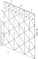
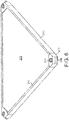
- Figure 1a shows a first embodiment of a flooring system 1 for supporting one or more people and for generating electricity from the motion of those people as they walk across the flooring system.
- the flooring system 1 comprises a plurality of generators 100 and a plurality of tiles 200.
- the plurality of tiles 200 collectively define a floor surface for walking on.
- Each generator 100 comprises a housing 105 and a support 110(see figure 8 ).
- the support 110 is movable with respect to the housing 105.
- Each generator 100 is arranged to generate electricity from linear motion of its support 110 in a first direction.
- Each support 110 is biased by biasing means towards a rest location to provide a restoring force following displacement. When the flooring system 1 is installed, the first direction will correspond with the vertical direction, and each support 110 will be biased by an upward force.
- the preferred form of the generator 100 is described in greater detail below. However, a generator having the form described in WO2011138585 could be used.
- each generator 100 supports a plurality of tiles 200.
- the supports 110 will be displaced from an equilibrium position. This will cause the generator(s)110 to generate electricity.
- the displaced support(s) 110 will then be returned to its/their equilibrium or rest position by the biasing means (not shown).
- Each displaced support 110 will move only over a small distance so as to avoid an unpleasant sensation for the user.
- the cumulative effect of many steps from many users over a large area can generate a significant amount of electricity.
- the tiles 200 are pivotably supported by the supports 110. It will be noted that this can prevent trip hazards from arising, since neighbouring tiles will move together.
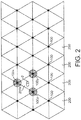
- each footstep 2 when a user steps on the flooring system, each footstep 2 (see figure 2 ) will move the support 110 of only one generator 100 (e.g., if the footstep 2 lands on a generator 100); or move the supports 110 of two generators, (e.g., if the footstep 2 lands on the boundary between two neighbouring tiles 200); or move the supports 110 of three generators 100 (e.g., if the footstep 2 lands in the middle of a tile 200).
- the biasing means is preferably a spring, but could be provided by a magnetic device, or a combination of both.
- Each tile 200 is supported by a plurality of supports 110.
- a user stepping on a tile 200 can provide motion to each of the corresponding supports 110 associated with the tile and thereby generate electricity via the corresponding plurality of generators 100. In doing so, each tile 200 will displace vertically and/or tilt by a small degree.
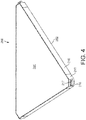
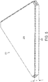
- Each tile 200 is generally planar with a first major surface 201 (see figure 3a ) and a second major surface 202 (see figure 4 ).
- the first major surface 201 forms an upper surface in use.
- the second major surface 202 forms a lower surface in use.
- the tiles 200 substantially tessellate to collectively form a substantially continuous floor surface.
- substantially is meant that the tiles 200 do not meet exactly along each edge, but that a small gap is provided therebetween (to allow for relative rotation of neighbouring tiles 200).
- a gap is provided between the multiple tiles 200 supported by that generator 100. The gaps along each edge and at each generator 100 are only small in comparison to the surface area of the floor surface taken up by the tiles 200.
- each tile is generally shaped as a triangle (most preferably, an equilateral triangle).
- a triangle most preferably, an equilateral triangle.
- the triangular shape may be slightly truncated in the corners. Since the corners are only truncated by a small amount, each tile 200 can be said to be generally triangular.
- each tile 200 is supported by exactly three supports with a support 110 supporting each corner of the tile 200.
- the tiles 200 are biased by the biasing means acting on the supports 110 to be flat and level when a user is not standing on the floor surface.
- the possible degree of tilting of the tiles 200 may be larger than if other arrangements were used. For example, if a user steps on the corner of a square tile 200, the opposite corner could protrude by a corresponding displacement. However, with triangular tiles, the movement of one corner represents the rotation of the tile about one edge, and so undesirable deformations of the floor, such as producing trip hazards, can be avoided for equivalent displacements.
- the longest dimension of each tile 200 is no more than 100cm. Preferably, the longest dimension of each tile is in the range 300mm to 700mm.
- the longest dimension would correspond to the distance between two opposite corners.
- the longest dimension is the length of one edge. This substantially corresponds to the distance between supports 110.
- each tile 200 has a thickness T that is as small as possible. This also reduces the need to excavate a large space for installation. However, the tiles must carry the weight of a user and so they must be rigid and strong. Thus, the inventors have designed the preferred composite tiles 200 shown in Figures 3a , 3b , and 3c .
- each tile 200 comprises a first sheet 206, and a second sheet 207, and a core 205 sandwiched therebetween.
- the core 205 is preferably a non-continuous layer, such as a foam layer or a honeycomb layer.
- the core 205 may comprise a polymer.
- the core 205 may comprise particles of wood and a resin.
- the core 205 may additionally or instead comprise: Nomex; polypropylene; chipboard; and/or fibre reinforced cement.
- One or both of the sheets 206, 207 may comprise a ceramic.
- one or both of the sheets 206, 207 may comprise a metal.
- one or both of the sheets 206, 207 may additionally or instead comprise: steel; and/or laminated ceramic.
- each tile comprises a platform 205, 206, 207 (see figure 3a ) and a frame 211 (see figure 3c ) that surrounds the perimeter of the major surfaces 201, 202 of the platform.
- the platform may comprise a further layer 235a, 235b (see figure 7 ) on top of, or forming part of, the first sheet 206.
- the further layer 235a, 235b may be formed of a preferred flooring material.
- the further layer 235a, 235b may be decorative and/or resistant to damage from the footsteps of people walking over it.
- the supports 110 of the generators 100 preferably support the frames 211 of the tiles 200 directly.
- Each frame 211 is formed of frame members comprising an edge member 210(see figure 3c ) extending along each edge of the major surfaces 201, 202 of the platform 205, 206, 207; 205, 206, 207, 235.
- edge member 210 (see figure 3c ) extending along each edge of the major surfaces 201, 202 of the platform 205, 206, 207; 205, 206, 207, 235.
- corner pieces 215 are provided, with the edge members 210 meeting at the corner pieces 215.
- the frame members are shaped so as to collectively define a seat in which the platform can be seated.
- Each edge member 210 may be formed as a strip from which a first lip 211 protrudes inwardly (for example, over all or a major portion of its length). If corner pieces 215 are provided, these may be formed as a bent strip from which a web 219 (see figure 3c ) extends to form a seat.
- the corners of the frame 211 are provided with features for pivoting engagement between the tile 200 and the generator 100.
- the corners of the frame 211 are provided with features that also allow sliding between the tile 200 and the generator 100.
- Complementary features may be provided on the generator 100, as discussed below.
- the corners of the frame 211 preferably comprise a rib 216 (see figure 4 ) extending therefrom (preferably, parallel to the major surfaces 201, 202 of the tile 200).
- a groove 217 is formed in the rib for reasons discussed below.
- the corners of the frame 211 preferably comprise an indent 218 (see figure 6 ) on the underside thereof.
- the indent 218 is preferably rounded.
- the indent 218 can allow rotation of the tile 200 in multiple degrees of freedom.
- the indent 218 is also elongated to allow sliding motion.
- the tile 200 may be provided with reinforcing ribs 290 to provide extra rigidity.
- a central stop 292 is also provided.
- the central stop 292 is arranged to contact with the ground if too great a force is applied to the tile 200. In this way, the generator 100 may be protected.
- the ribs 290 and stop 292 may be formed as part of the frame 211 or the platform.
- a flexible sealing strip 230 (see figure 7 ) is provided between the neighbouring edges of each adjacent tile 200. This can prevent the ingress of most solid materials (and, in some cases, liquids) into the area below the floor. Furthermore, and equally importantly, the sealing strip 230 acts to prevent a direct impact between adjacent tiles 200. The tiles 200 are rigid and so contact would produce noise as a user walks across the flooring system 1.
- the platform preferably comprises a first sheet 206, a second sheet 207, a core 205, and a further layer 235a , 235b of flooring material.
- a flexible sealing strip 230 extends between the two tiles 200.
- the strip of the frame member 210a extends from the first major surface 201 such that it is flush with the surface 201 of the flooring material layer 235.
- the frame can protect the further layers 235a, 235b of the flooring material.
- the lips 211a provides support for the platforms.
- the strip of the frame member 210a extends below the level of the lip 211a.
- the supporting flange 212 may extend over all or a major portion of the length of the strip.
- each sealing strip 230 is supported by only a single supporting flange 212.
- the simplest way to achieve this is by using two types of tile 200a, 200b.
- the first type of tile 200a includes a supporting flange 212 along every edge, while the second type of tile 200b does not include any supporting flange 212.
- the two types of tile 200a, 200b can then be arranged such that for a given tile 200 every adjacent tile 200 is of a different type.
- the strip forming the frame member 210b extends from the first major surface 201 such that it is flush with the surface of the flooring material layer 235b.
- the strip for this tile 200b extends only as far as lip 211b on which the platform is seated.
- the supporting flange 212 of the strip of the first tile 200a extends below the strip of the second tile 200b by a distance G.
- Every other tile may have edge members 210 formed with a second lip 211 protruding from the strip (for example, over all or a major portion of its length).
- the supporting flanges are used to support the flexible sealing strips 230.
- the flexible sealing strip 230 is formed of a compressible material to not hinder the relative movement of the neighbouring tiles 200.
- the strip 230 may comprise or be formed of: rubber; neoprene; TPV; TPE; and/or polymeric materials.
- the generators 100 are preferably provided in a regular array so as to support the corners of the tiles 200.
- Other arrangements can be used (for example, the generators could be provided at the midpoints of the edges of the tiles), but the disclosed arrangement is preferable.
- the corners of multiple tiles 200 tiles sit on a single support 110.
- six tiles 200 sit on each support 110.
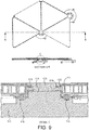
- each generator 100 comprises an housing 105, having an aperture 107 through which part of the support 110 extends.
- the generator 100 may comprise two or more adjustable feet 123 extending from the housing 105 to enable its height and orientation to be adjusted.
- the generator 100 may be an electromagnetic generator comprising a rotor (not shown) that rotates about an axis parallel with the first direction.
- the rotor may be driven to rotate by motion of the support 110 in the first direction.
- Suitable arrangements of magnets and coils may be provided (not shown) to generate electricity from the rotation of the rotor.
- WO2011138585 discloses an optional form of generator.
- each support 110 in the first direction should be limited to by no more than 20mm.
- the range of movement should be in the range 5mm to 10mm.
- Each generator 100 may comprise a biasing means such as one or more spring(s) for biasing the support 110 in the first direction to a nominal or rest position.
- the biasing means may be provided separately from each generator 100. If the biasing means act directly on the tiles 200 to level the tiles 200 when the floor surface is not carrying the weight of a user, then they will necessarily bias the supports 110 back to the nominal or rest positions.
- Each support 110 comprises a plurality of pivots via which each tile 200 is supported, wherein each pivot allows one tile 200 to tilt relative to the support 100, and preferably also to slide relative to the support 100.
- each support 110 comprises a platform 111 upon which is located a gasket 112.
- the gasket 112 is preferably made of resilient material to muffle the sound of footsteps.
- the gasket 112 comprises or is formed of: rubber; neoprene; TPV; TPE; and/or a polymeric material.
- the tiles 200 are supported on the gasket 112.
- the gasket 112 comprises a plurality of rollers 116 (see figures 8 and 9 ).
- the rollers 116 may be seated in complementarily-shaped indents 113 (see figure 8 ) in the platform 111.
- Rollers 116 may be any suitable shape, e.g. cylindrical, but are preferably spherical or generally spherical.
- the rollers 116 are complementary to the indents 218 in the tiles 200 described above.
- the rollers 116 and indents 113, 218 can allow rotation of the tile 200 in multiple degrees of freedom.
- one roller 116 is provided per tile 200. (That is, in the preferred embodiment, six rollers 116 would be provided on each support 110) .
- the support 110 may comprise a neck 114 extending from the platform 111.
- the gasket 112 may comprise a sleeve 117 with a flange 115 extending from the base thereof.
- the sleeve 117 fits around the neck 114 of the support 110 with the flange 115 resting on the surface of the platform 111.
- the rollers 116 extend through the flange.
- Each roller 116 may be a separate article rotating about a central axis of the flange 115. However, since the amount of movement of each roller 116 need not be great, each may be manufactured integrally with the flange gasket 112. For example, the roller 116 may be linked to the flange 115 of the gasket 112 via a resilient web (e.g., a narrow web of the gasket 112 material) that twists and/or stretches as the roller 116 rotates.
- a resilient web e.g., a narrow web of the gasket 112 material
- a cap 120 may be provided.
- the cap 120 may prevent the tile 200 from translating relative to the support 110.
- the cap 120 may be fixed to the support 110 (for example, the neck 114 of the support 110) by any fixing means (e.g., by screws).
- an O-ring 122 and/or further gasket made from resilient materials may be provided therebetween.
- the O-ring 122 or further gasket comprises or is formed of: rubber; neoprene; TPV; TPE; and/or a polymeric material.
- Figure 9 shows a cross-section through the corners of two tiles 200, through a generator 100 and through two rollers 116.
- the rigid tiles 200 do not contact the rigid components of the support 110 or cap 120 directly, but are supported by the resilient materials of the gasket 112 and O-ring 122.
- rib 216 extending from the corners of the frame 211 engages the underside of the cap 120 via the O-ring 122 or gasket, while the underside of the frame 211 sits on the gasket 112.
- the groove 217 formed in the rib 216 corresponds to the shape of the O-ring 122.
- the frames 211 and generators 100 can be installed first. Then the height and level of the generators 100 may be adjusted until the frames 211 are all level. The platforms of the tiles 200 may then be placed into the frames 211. The height and level of the generators 100 may be adjusted using the feet 123. The seals 230 may then be inserted between neighbouring tiles.
- the inventors have realised that the flooring system 1 can be used, in addition to generating electricity, to collect data about the presence and/or movement of people across the flooring system 1.
- the flooring system 1 may comprise a data processing system 300 in communication with each generator for receiving the electrical power generated thereby.
- an average power output per user can be determined. For example, under controlled conditions a number of people can be instructed to walk across the floor, and the power output measured. The measured power can be averaged over time and divided by the number of people to provide the average power output per person. This predetermined value can be stored by the system 1.
- the data processing system 300 is arranged to estimate the number of people supported by the plurality of tiles by: calculating a total power output of the plurality of generators; and dividing the total output by the stored predetermined value.
- the occurrence of a footstep 2 on a tile 200 can be noted by the data processing system 300.
- the identification of a tile 200 as it is contacted by a footstep 2 may be stored by the data processing system 300.
- the data processing system 300 may record the time and location (the particular tile 200) of each footstep 2.
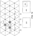
- the inventors have also realised that the support of a tile 200x using three or more generators 100x, 100y, 100z allows information to be gathered about the location of a footstep 2 on a particular tile 200 the flooring system 1.
- the electrical signal generated by each of the three generators 100x, 100y, 100z can be compared. For example, the voltage generated by the generators 100 can be recorded. If the footstep is closer to one generator 100 than another, then that generator will generate a greater voltage.
- the voltages provided by the generators 100x, 100y, 100z supporting a tile 200x it is possible to identify the relative distance between the generators 100, and thereby determine the location of the footstep 2 (i.e., the centre of gravity of the footstep 2) on each tile 200.
- an electromagnetic generator comprising a rotor that rotates about an axis, it is possible to provide a signal representing the speed of rotation (or rotational frequency) of the rotor. This can also provide an indication of a footstep 2.
- the generator 100 can be configured to generate a signal representing a force applied to the generator 100 by the tile 200.
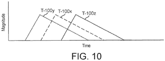
- the signal generated by each of the three generators 100x, 100y, 100z will reach a maximum at a different time.
- a rough representation of a time series of three signals T-100x, T-100y, T-100z is shown in Figure 10 .
- the centre of gravity of the footstep 2 will move towards or away from the generator 100x, 100y, 100z resulting in the maximum values of the signals T-100x, T-100y, T-100z being achieved at different times.
- the data processing system 300 is arranged to determine a time difference between the signals received from the generators 100 supporting that tile 200 to estimate the direction of the user's motion.
- the data processing system 300 is arranged to determine the order in which the signals received from the generators 100 supporting that tile 200 reach a maximum value.
- the order in which the generators 100x, 100y, 100z reach the maximum value is indicative of the direction of the footstep 2.
- the flooring system 1 can provide an estimate of location of a footstep (either coarsely, identifying a particular tile, or more accurately, identifying the location on that tile) and its direction.
- the size of a user may be estimated. This can be configured by instructing users of known mass to walk across the flooring system 1 and carrying out appropriate measurements.
- the user's speed may be taken into account.
- a user running can generate more energy than a user walking slowly.
- Speed may be derived from the output of a tracking algorithm (discussed below), the duration of the footstep 2, and/or the time series data for each footstep 2 (which characterises the variation in footstep force over time). Again, this can be configured by instructing users of known mass to walk across the flooring system 1 at a known pace and carrying out appropriate measurements.
- the occurrence of a footstep 2 on a tile 200 can be noted by the data processing system 300, which may apply a tracking algorithm to track the passage of a walker across the flooring system 1.
- the arrangement of the tiles 200 may be stored in the data processing system 300.
- the identification of a tile 200 as it is contacted by a footstep 2 may be provided as an input to a tracking algorithm, which may be configured to track the path of the user walking across the flooring system 1. That is, the data processing system 300 may record the time and location of each footstep 2, and will label each footstep 2 as corresponding to the same user as another footstep 2.
- Suitable tracking algorithms are well known in the art, and include, for example: Kalman filters; and/or probability hypothesis density tracker.
- the identification of a tile 200 as it is contacted by a footstep 2 may be supplemented with time series data representing the time series output of each generator 100 corresponding to the tile 200 to provide as an input to a tracking algorithm.
- time stamp the data provided to the tracker.
- the input to the tracking algorithm is the location of a footstep 2 and the direction of the footstep 2.
- the input to the tracking algorithm is one or more of: the location of a footstep 2, the direction of the footstep 2, the magnitude (power or energy) of the footstep, and data representing an estimate of the mass of the user.
- the generators 100 provide an output signal representing the force applied periodically, after a time period of from 10ms to 50ms.
- the output signal may be triggered by a footstep and last for between 250ms and 750ms, preferably 500ms.
- the data processing system 300 can therefore output an estimate of one or more of:
- generators to harvest energy from the flooring system 1
- the advantages of the tracking methodology would be available if the generators were simply replaced with some form of pressure sensor, such as a piezo-electric sensor. Indeed, in this context, the generator can be thought of as a sensor.
- the flooring system 1 may additionally comprise a plurality of electromagnetic receivers for receiving identifiers transmitted by mobile communications devices and for identifying the strength of reception of each of the identifiers.
- each receiver is located in the space below the corresponding tile 200.
- the receivers are arranged to receive identifiers transmitted by mobile phones (cell phones).
- the receivers are arranged to receive RFID, Bluetooth or Zigbee signals identifying a mobile phones.
- the sensors are arranged to activate the receiver corresponding to that tile 200 (alternatively a receiver could be associated with each generator).
- the receiver can receive multiple transmitted identifiers measure the strength of reception corresponding to each transmission.
- the system assumes that the greatest strength of reception can correspond to the mobile communications device carried by the user that stepped on the tile 200.
- the receiver when activated, is arranged to receive any transmitted identifiers and to determine the identifier corresponding to the reception of greatest strength.
- the data processing system 300 is in communication with each sensor and each receiver, and is arranged to generate data representing the time at which the force was sensed, the tile 200 to which the force was applied, and the determined identifier received by the receiver corresponding to that tile 200. One or each of these data can be used to supplement the input to the tracker.
- each generator has associated therewith a transmitter that transmits a signal (for example, a code denoting its own identity).
- Such a flooring system 1 comprises: a plurality of tiles for supporting one or more people, each tile coupled to one or more sensors for sensing a force applied to the tile; and a plurality of electromagnetic transmitters for transmitting a signal for reception by one or more mobile communications device(s), each transmitter corresponding to a respective generator, wherein: in response to a force applied to a generator the power generated activates a transmitter corresponding to that generator, wherein: the flooring system further comprising a remotely located data processing system (e.g.
- a cloud based server connected to the mobile cellular network), in communication with each mobile communication device to receive data therefrom; and the data processing system is arranged to generate output data representing the time at which the force was sensed, the tile to which the force was applied, and the determined identifier received by the receiver.
- the system works in a similar way to a known beacon system (e.g the Apple ibeacon (trade mark) or Google Eddystone (trade mark) technologies).
- transmission of the location signals to the mobile communications devices is occasioned by a generator using a user's foot step to generate power to initiate a transmission.
- Each transmitter / generator combination acts as a beacon.
- a signal can be added to the beacon part of the system based on the generator status.
- the transmitter is located below the corresponding tile.
- the mobile telephone will have thereon software (e.g., an app), programmed to respond to the receipt of the transmission by sending an identifying code to the central receiver to the cloud based server.
- software e.g., an app
- a WIFI communications system can be incorporated into the system, typically located in the floor, to allow communications of each mobile telephone with the cloud based server.
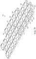
- FIG 11 shows a base 600 upon which the flooring system 1 can be installed.
- the base 600 comprises a plurality of slabs 500 (preferably formed of or comprising concrete).
- Each slab 500 includes a raised pedestal 510 on which a generator 100 of the flooring system 1 may be placed. Drainage holes 535 are also provided to provide a path for the egress of liquid on the base 600. Any liquid spilled upon the flooring system 1 that passes the sealing strips, O-rings, and/or gaskets, will thus not pool around a generator 100. Moreover, the slabs 500 may be provided with an inclined upper surface, sloping away from the pedestals 510 and towards the drainage holes 535, so that gravity draws the liquid away from the pedestals 510.
- the slabs 500 may include interlocking features 515, 520, 525 to enable each slab 500 to interlock with another slab 500.
- each slab 500 comprises a plurality of tabs 515 and a plurality of complementarily-shaped cavities 540 spaced along two or more edges.
- the tabs 515 preferably have a trapezium shape such that the cavities 540 are defined therebetween.
- one or more drainage holes 535 are provided in one, more or all of the tabs 515.
- each slab comprises a plurality of pedestals 510 spaced in a line that terminates at one end in a tab 520 and another end in a complementarily-shaped cavity 525.
- the above described flooring system 1, or a similar system can be used in combination with a user's mobile phone 1001 (or some other mobile communications device) to monitor the usage of the floor by correlating footsteps 2 sensed by the flooring system 1 (using either sensors or generators).
- footsteps 2 sensed by a motion sensor 1002, such as an accelerometer, in the mobile phone 1001 can be correlated with those sensed by the floor system.
- a pedometer associated with the flooring system 1 in order to verify that the measured steps have taken place, and have taken place on the flooring system 1.
- the correlation can take place either in the mobile phone 1001 or in the remote cloud based server 1010.
- the remote server 1010 can be connected to a processor or processors hard wired to the generators, to communicate therewith.
- Each tile 200 is coupled to at least one sensor, which is preferably in the form of a generator 100.
- the sensor is suitable for sensing when a force is applied to the tile 200.
- multiple sensors 100x, 100y, 100z are provided for each tile, they can assign a footstep 2 to a particular tile 200 or position on that tile if all the sensors 100x, 100y, 100z for that tile 200 sense a footstep 2. If the footstep is sensed by all sensors 100x, 100y, 100z for two neighbouring tiles, the footstep 2 can be allotted to the tile 200 with the greatest total sensed force.
- Each generator 200 is associated with a transmitter (not shown) for transmitting a signal for reception by the mobile communications device 1001.
- the transmitter transmits a wireless signal that may comprise one or more of: a Wi-Fi signal; a Bluetooth signal; an NFC signal; and/or an RF signal.
- the generators 100 are arranged to activate the transmitters associated with the generators.
- the transmitters may be located below or within the corresponding tile 200.
- a motion sensor 1002 may be part of the mobile phone 1001, or may be an external device in communication with the mobile phone 1001 (for example, the motion sensor 1002 may be attachable/attached to the user). In either case, the motion sensor 1002 is arranged to sense a predetermined motion for identifying a step made by a carrier of the mobile phone 1001. For example, a threshold may be determined through experimentation that represents the acceleration of the motion sensor 1002 when attached to a user taking a footstep 2. When the threshold is exceeded, a footstep 2 can be considered to have taken place.
- the mobile phone 1001 is arranged to receive a transmission from the transmitters and to match the received transmission with the sensed motion for confirming that a footstep 2 has taken place. This can be done, for example, by confirming that the time between the received transmission and the sensed motion is less than a threshold.
- the mobile communications device 1001 is arranged to count the footsteps made on the tiles.
- the transmitters can transmit to the mobile communications device 1001 a variety of data. This may include: the time of the footstep 2; the identity of that tile 200; the location of that tile 200; the location of the footstep 2; and/or the power generated by the footstep 2 when the sensors 100x, 100y, 100z are in the form of generators 100.
- a plurality of users, each carrying a mobile phone 1001 can use the flooring system 1 and a remote server may be provided 101 to monitor all of the users.
- Each mobile phone 1001 may be arranged to transmit to the remote server 1010 output data representing one or more of: a count of footsteps 2 made upon the tiles 200; the timing of each footstep 2; the identity of the tile 200 sensing each footstep 2; the location of that tile 200 for each footstep; the location of each footstep 2 on each tile 200; and/or the energy and/or power generated by each footstep 2 when the sensors 100x, 100y, 100z are in the form of generators 100.
- the flooring system 1 can communicate data directly to the remote server 1010.
- the flooring system 1 can be connected to the remote server 1010 or can communicate data directly to the remote server 1010 wirelessly.
- the matching of footsteps 2 sensed by the motion sensor 1002 with footsteps 2 sensed by the flooring system 1 can be carried out using the remote server 1010.
- the system can operate without communication between transmitters/receivers in the floor and the mobile telephones. Instead the mobile telephones use the motion sensors (e.g. accelerometers) incorporated therein or connected thereto to transmit signals to a cloud based server indicating the timing of steps taken by the user.
- the generators in the floor will then be associated with transmitters that separately transmit via a communications link associated therewith their generated signal to the cloud based server.
- the cloud based server then correlates the signals sent by the mobile phone(s) with the signals generated by the generator(s) to identify a pedestrian and track the pedestrian's movement.
- the remote server can calculate any of the data calculated by the mobile phone 1001.
Landscapes
- Engineering & Computer Science (AREA)
- Architecture (AREA)
- Physics & Mathematics (AREA)
- Combustion & Propulsion (AREA)
- Chemical & Material Sciences (AREA)
- General Engineering & Computer Science (AREA)
- Health & Medical Sciences (AREA)
- General Physics & Mathematics (AREA)
- Life Sciences & Earth Sciences (AREA)
- Structural Engineering (AREA)
- Civil Engineering (AREA)
- Mechanical Engineering (AREA)
- Power Engineering (AREA)
- Theoretical Computer Science (AREA)
- Environmental & Geological Engineering (AREA)
- Electromagnetism (AREA)
- Computer Networks & Wireless Communication (AREA)
- Geophysics (AREA)
- General Life Sciences & Earth Sciences (AREA)
- Remote Sensing (AREA)
- Geology (AREA)
- Biophysics (AREA)
- Molecular Biology (AREA)
- Dentistry (AREA)
- Oral & Maxillofacial Surgery (AREA)
- Human Computer Interaction (AREA)
- Pathology (AREA)
- Biomedical Technology (AREA)
- Heart & Thoracic Surgery (AREA)
- Medical Informatics (AREA)
- Physiology (AREA)
- Surgery (AREA)
- Animal Behavior & Ethology (AREA)
- General Health & Medical Sciences (AREA)
- Public Health (AREA)
- Veterinary Medicine (AREA)
- Toxicology (AREA)
- Floor Finish (AREA)
Claims (15)
- Système de surveillance de pas, comprenant :un ou plusieurs dispositifs de communication mobile (1001); etune pluralité de carreaux (200) pour supporter une ou plusieurs personnes, chaque carreau (200) étant couplé à au moins un capteur de force pour détecter une force appliquée au carreau (200), et chaque capteur de force étant associé à au moins un émetteur pour émettre un signal pour la réception par le ou les dispositifs de communication mobile (1001);caractérisé en ce que :chaque capteur de force comprend un générateur (100) alimenté par un piéton marchant sur un carreau (200), le générateur (100) générant un signal électrique pour activer l'émetteur associé à celui-ci ; et,en réponse à une force appliquée à un carreau (200), le ou les capteurs de force sont conçus pour activer le ou les émetteurs associés à ceux-ci ;et chaque dispositif de communication mobile (1001) est conçu pour recevoir une ou plusieurs transmissions à partir du ou des émetteurs.
- Système tel que revendiqué dans la revendication 1, dans lequel :chaque dispositif de communication mobile (1001) comprend un capteur mobile pour détecter le mouvement du dispositif ou est en communication avec un capteur de mouvement (1002) porté par un utilisateur pour détecter le mouvement de l'utilisateur ; chaque capteur de mouvement (1002) de chaque dispositif de télécommunication mobile (1001) ou en communication avec celui-ci permet l'identification d'un pas de l'utilisateur ; etchaque dispositif de communication mobile (1001) met en correspondance une ou plusieurs transmissions reçues à partir du ou des émetteurs avec un mouvement détecté par le capteur de mouvement (1002) de celui-ci ou en communication avec celui-ci pour confirmer qu'un pas a été fait par l'utilisateur.
- Système de la revendication 2, dans lequel chaque dispositif de communication mobile (1001) est conçu pour mettre en correspondance une transmission reçue avec le mouvement détecté en confirmant que le temps entre la transmission reçue et le mouvement détecté est inférieur à un seuil.
- Système de l'une quelconque des revendications 1 à 3, dans lequel le dispositif de communication mobile (1001) est conçu pour :faire la distinction entre de multiples transmissions reçues en sélectionnant la transmission ayant l'intensité de signal la plus élevée ; etmettre en correspondance la transmission sélectionnée avec le mouvement détecté en confirmant que le temps entre la transmission reçue et le mouvement détecté est inférieur à un seuil.
- Système de l'une des revendications précédentes, dans lequel les émetteurs émettent au dispositif de communication mobile (1001) un élément de données représentant au moins l'un :du moment du pas (2) ;de l'identité de ce carreau (200) ;de l'emplacement de ce carreau (200) ;de l'emplacement du pas (2) ; et/oude la puissance générée par le pas (2).
- Système de l'une des revendications précédentes, dans lequel le dispositif de communication mobile (1001) est conçu pour compter les pas (2) faits sur les carreaux (200) .
- Système de l'une des revendications précédentes, comprenant en outre un serveur distant (1010) en communication avec le dispositif de communication mobile (1001), où le dispositif de communication mobile (1001) est conçu pour émettre au serveur distant (1010) des données de sortie représentant un ou plusieurs éléments parmi :un total de pas (2) faits sur les carreaux (200) ;le moment de chaque pas (2) ;l'identité du carreau (200) détectant chaque pas (2) ;l'emplacement de ce carreau (200) pour chaque pas (2) ;l'emplacement de chaque pas (2) ; et/oul'énergie et/ou la puissance générées par chaque pas (2).
- Système de l'une des revendications précédentes, dans lequel l'émetteur est situé : en dessous du carreau correspondant (200) ou dans celui-ci.
- Procédé de surveillance de pas, comprenant les étapes consistant à :détecter une force appliquée à un carreau (200) en utilisant un capteur de force et, en réponse à celle-ci, émettre un signal à partir d'un émetteur associé à ce carreau (200) ;caractérisé par l'étape consistant à :recevoir le signal émis avec un dispositif de communication mobile (1001) tenu par l'utilisateur ; oùle capteur de force comprend un générateur (100) et la force appliquée au carreau (200) est utilisée par le générateur (100) pour générer une puissance qui est ensuite utilisée pour alimenter l'émetteur.
- Procédé tel que revendiqué dans la revendication 9, comprenant en outre les étapes consistant à :détecter un mouvement prédéterminé d'un utilisateur en utilisant un capteur de mouvement (1002) qui est attaché à l'utilisateur ou porté par celui-ci et en communication avec le dispositif de communication mobile (1001) ; etmettre en correspondance la transmission reçue avec le mouvement détecté en utilisant le dispositif de communication mobile (1001) pour confirmer qu'un pas a eu lieu.
- Procédé de la revendication 10, dans lequel l'étape de mise en correspondance comprend :
la mise en correspondance d'une transmission reçue avec le mouvement détecté en confirmant que le temps entre la transmission reçue et le mouvement détecté est inférieur à un seuil. - Procédé de la revendication 10 ou 11, comprenant en outre les étapes consistant à :faire la distinction entre de multiples transmissions reçues en sélectionnant la transmission ayant l'intensité de signal la plus élevée en utilisant le dispositif de communication mobile (1001) ; etmettre en correspondance la transmission sélectionnée avec le mouvement détecté en confirmant que le temps entre la transmission reçue et le mouvement détecté est inférieur à un seuil.
- Procédé de l'une quelconque des revendications 9 à 12, dans lequel l'étape consistant à émettre un signal à partir d'un émetteur associé à ce carreau (200) comprend l'émission d'un élément de données représentant au moins l'un :du moment du pas (2) ;de l'identité de ce carreau (200) ;de l'emplacement de ce carreau (200) ;de l'emplacement du pas (2) ; et/oude la puissance générée par le pas (2).
- Procédé de l'une quelconque des revendications 9 à 13, comprenant en outre l'étape consistant à compter les pas (2) faits sur les carreaux (200) en utilisant le dispositif de communication mobile (1001).
- Procédé de l'une quelconque des revendications 9 à 14, comprenant en outre l'étape consistant à émettre, à partir du dispositif de communication mobile (1001) au serveur distant (1010), des données de sortie représentant un ou plusieurs éléments parmi :un total de pas (2) faits sur les carreaux (200) ;le moment de chaque pas (2) ;l'identité du carreau (200) détectant chaque pas (2) ;l'emplacement de ce carreau pour chaque pas (2) ;l'emplacement de chaque pas (2) ; et/oul'énergie et/ou la puissance générées par chaque pas (2).
Applications Claiming Priority (3)
| Application Number | Priority Date | Filing Date | Title |
|---|---|---|---|
| GB1516239.9A GB2542204B (en) | 2015-09-14 | 2015-09-14 | Flooring system |
| GBGB1608200.0A GB201608200D0 (en) | 2015-09-14 | 2016-05-10 | Flooring system |
| PCT/GB2016/052845 WO2017046587A1 (fr) | 2015-09-14 | 2016-09-14 | Système de revêtement de sol |
Publications (2)
| Publication Number | Publication Date |
|---|---|
| EP3350440A1 EP3350440A1 (fr) | 2018-07-25 |
| EP3350440B1 true EP3350440B1 (fr) | 2020-06-10 |
Family
ID=54363127
Family Applications (1)
| Application Number | Title | Priority Date | Filing Date |
|---|---|---|---|
| EP16770313.1A Active EP3350440B1 (fr) | 2015-09-14 | 2016-09-14 | Système de revêtement de sol |
Country Status (5)
| Country | Link |
|---|---|
| US (1) | US10333370B2 (fr) |
| EP (1) | EP3350440B1 (fr) |
| CN (1) | CN108474360B (fr) |
| GB (2) | GB2542204B (fr) |
| WO (1) | WO2017046587A1 (fr) |
Families Citing this family (10)
| Publication number | Priority date | Publication date | Assignee | Title |
|---|---|---|---|---|
| CA2814183C (fr) * | 2010-10-12 | 2018-07-10 | New York University | Appareil de detection utilisant des tuiles, capteur comprenant un ensemble de plaques, identification d'objet pour surfaces tactiles multipoints et procede |
| US11063415B2 (en) * | 2019-01-16 | 2021-07-13 | Raymond & Lae Engineering, Inc. | Raised access floor panel with embedded sensors |
| JP2021014711A (ja) * | 2019-07-11 | 2021-02-12 | 凸版印刷株式会社 | センサ付き床材 |
| US10851807B1 (en) * | 2019-12-19 | 2020-12-01 | King Abdulaziz University | Energy generating system using floor tiles and fluid/gas movement |
| IL276140B (en) * | 2020-07-19 | 2021-08-31 | Ron Zauderer | Modular floor system and modules for it |
| CN112102363A (zh) * | 2020-09-14 | 2020-12-18 | 北京数衍科技有限公司 | 行人轨迹跟踪方法和装置 |
| CN112767677A (zh) * | 2020-11-05 | 2021-05-07 | 上海城市交通设计院有限公司 | 一种智慧复合无障碍通道 |
| US11699048B2 (en) | 2020-11-30 | 2023-07-11 | Huawei Technologies Co., Ltd. | Wireless sensing units, systems, methods, and media |
| CN113916058B (zh) * | 2021-11-08 | 2023-09-01 | 娄少回 | 远程约束装置及其面板、活动撑杆和支撑座 |
| GB2613630A (en) * | 2021-12-10 | 2023-06-14 | Sapphire Balconies Ltd | Tile spacer element |
Family Cites Families (12)
| Publication number | Priority date | Publication date | Assignee | Title |
|---|---|---|---|---|
| US6515586B1 (en) * | 1998-12-18 | 2003-02-04 | Intel Corporation | Tactile tracking systems and methods |
| US6707386B1 (en) * | 2002-05-28 | 2004-03-16 | Carla J. Pruisner | Security mat alarm system |
| EP1616196A4 (fr) * | 2003-04-03 | 2009-05-20 | Univ Virginia | Procede et systeme de caracterisation de la demarche humaine et de determination passive des chutes a partir de vibrations du plancher |
| DE102007001225A1 (de) | 2007-01-08 | 2008-07-10 | Future-Shape Gmbh | Flächenverkleidungselement, Flächenverkleidungselement-Anordnung und Verfahren zum Herstellen eines Flächenverkleidungselementes |
| EP2425068B1 (fr) * | 2009-04-27 | 2015-06-03 | Mohawk Carpet Corporation | Systèmes de planchéiage et procédé d'utilisation |
| GB201007497D0 (en) | 2010-05-05 | 2010-06-23 | Pavegen Systems Ltd | Energy harvesting |
| CN202012029U (zh) * | 2011-04-28 | 2011-10-19 | 欧阳晓东 | 一种压力感应发光地砖和使用该地砖的触控屏幕 |
| FR2978974B1 (fr) * | 2011-08-12 | 2013-08-02 | Claude Desgorces | Revetement de sol |
| IT1412165B1 (it) * | 2012-05-17 | 2014-11-20 | Florim Ceramiche S P A | Sistema sensibile di rivestimento |
| WO2016118797A1 (fr) * | 2015-01-22 | 2016-07-28 | Interface, Inc. | Système de revêtement de sol avec capteurs |
| CN106585536A (zh) * | 2017-01-06 | 2017-04-26 | 北京微能高芯科技有限公司 | 一种车辆信息监测自供电系统 |
| CN107142871B (zh) * | 2017-05-04 | 2019-01-22 | 江苏理工学院 | 一种磁性缓冲道路隔离带装置 |
-
2015
- 2015-09-14 GB GB1516239.9A patent/GB2542204B/en active Active
-
2016
- 2016-05-10 GB GBGB1608200.0A patent/GB201608200D0/en not_active Ceased
- 2016-09-14 CN CN201680060170.6A patent/CN108474360B/zh active Active
- 2016-09-14 US US15/759,783 patent/US10333370B2/en active Active
- 2016-09-14 EP EP16770313.1A patent/EP3350440B1/fr active Active
- 2016-09-14 WO PCT/GB2016/052845 patent/WO2017046587A1/fr active Application Filing
Non-Patent Citations (1)
| Title |
|---|
| None * |
Also Published As
| Publication number | Publication date |
|---|---|
| EP3350440A1 (fr) | 2018-07-25 |
| WO2017046587A1 (fr) | 2017-03-23 |
| CN108474360B (zh) | 2020-02-18 |
| US10333370B2 (en) | 2019-06-25 |
| CN108474360A (zh) | 2018-08-31 |
| GB201516239D0 (en) | 2015-10-28 |
| GB201608200D0 (en) | 2016-06-22 |
| GB2542204A (en) | 2017-03-15 |
| US20180342929A1 (en) | 2018-11-29 |
| GB2542204B (en) | 2019-10-23 |
Similar Documents
| Publication | Publication Date | Title |
|---|---|---|
| EP3350440B1 (fr) | Système de revêtement de sol | |
| EP3350439B1 (fr) | Système de revêtement de sol | |
| US10891567B2 (en) | System and interfaces for managing workplace events | |
| US11170616B2 (en) | System and interfaces for managing workplace events | |
| US9691240B2 (en) | Floor covering system with sensors | |
| EP2425068B1 (fr) | Systèmes de planchéiage et procédé d'utilisation | |
| US9619987B2 (en) | Floor covering | |
| US7916035B2 (en) | Device for a bed alarm | |
| KR101629981B1 (ko) | Rtls 태그 장치 및 위치추적 시스템 | |
| US20130154441A1 (en) | Flooring system and floor tile | |
| US20180121861A1 (en) | System and interfaces for managing workplace events | |
| US9881189B2 (en) | Surface material enhancement with radio frequency identification (RFID) tags | |
| Banerjee et al. | Improving floor localization accuracy in 3D spaces using barometer | |
| CN109314835A (zh) | 基于多个信号和配置的地理围栏 | |
| KR102057916B1 (ko) | 스마트 틸트 플레이트 시스템, 그리고 이의 구동 방법 | |
| EP2850601A1 (fr) | Système de détection couvrant | |
| WO2017160812A1 (fr) | Système et interfaces de gestion d'événements sur le lieu de travail | |
| EP0373724B1 (fr) | Procédé et matériau antiglissant pour maintenir un paillasson ou petit tapis en place | |
| EP4365387A1 (fr) | Carreau, procédé d'échange de signaux avec un carreau et procédé de fabrication d'un carreau | |
| KR102018131B1 (ko) | 가시광 기반의 위치 인식을 이용한 서비스 제공 방법 및 이를 위한 장치 | |
| CA3023269A1 (fr) | Systeme et interfaces de gestion des evenements sur les lieux de travail |
Legal Events
| Date | Code | Title | Description |
|---|---|---|---|
| STAA | Information on the status of an ep patent application or granted ep patent |
Free format text: STATUS: THE INTERNATIONAL PUBLICATION HAS BEEN MADE |
|
| PUAI | Public reference made under article 153(3) epc to a published international application that has entered the european phase |
Free format text: ORIGINAL CODE: 0009012 |
|
| STAA | Information on the status of an ep patent application or granted ep patent |
Free format text: STATUS: REQUEST FOR EXAMINATION WAS MADE |
|
| 17P | Request for examination filed |
Effective date: 20180413 |
|
| AK | Designated contracting states |
Kind code of ref document: A1 Designated state(s): AL AT BE BG CH CY CZ DE DK EE ES FI FR GB GR HR HU IE IS IT LI LT LU LV MC MK MT NL NO PL PT RO RS SE SI SK SM TR |
|
| AX | Request for extension of the european patent |
Extension state: BA ME |
|
| DAV | Request for validation of the european patent (deleted) | ||
| DAX | Request for extension of the european patent (deleted) | ||
| STAA | Information on the status of an ep patent application or granted ep patent |
Free format text: STATUS: EXAMINATION IS IN PROGRESS |
|
| 17Q | First examination report despatched |
Effective date: 20190128 |
|
| GRAP | Despatch of communication of intention to grant a patent |
Free format text: ORIGINAL CODE: EPIDOSNIGR1 |
|
| STAA | Information on the status of an ep patent application or granted ep patent |
Free format text: STATUS: GRANT OF PATENT IS INTENDED |
|
| INTG | Intention to grant announced |
Effective date: 20190801 |
|
| GRAJ | Information related to disapproval of communication of intention to grant by the applicant or resumption of examination proceedings by the epo deleted |
Free format text: ORIGINAL CODE: EPIDOSDIGR1 |
|
| STAA | Information on the status of an ep patent application or granted ep patent |
Free format text: STATUS: EXAMINATION IS IN PROGRESS |
|
| GRAP | Despatch of communication of intention to grant a patent |
Free format text: ORIGINAL CODE: EPIDOSNIGR1 |
|
| INTC | Intention to grant announced (deleted) | ||
| STAA | Information on the status of an ep patent application or granted ep patent |
Free format text: STATUS: GRANT OF PATENT IS INTENDED |
|
| INTG | Intention to grant announced |
Effective date: 20200102 |
|
| GRAS | Grant fee paid |
Free format text: ORIGINAL CODE: EPIDOSNIGR3 |
|
| GRAA | (expected) grant |
Free format text: ORIGINAL CODE: 0009210 |
|
| STAA | Information on the status of an ep patent application or granted ep patent |
Free format text: STATUS: THE PATENT HAS BEEN GRANTED |
|
| AK | Designated contracting states |
Kind code of ref document: B1 Designated state(s): AL AT BE BG CH CY CZ DE DK EE ES FI FR GB GR HR HU IE IS IT LI LT LU LV MC MK MT NL NO PL PT RO RS SE SI SK SM TR |
|
| REG | Reference to a national code |
Ref country code: GB Ref legal event code: FG4D |
|
| REG | Reference to a national code |
Ref country code: CH Ref legal event code: EP Ref country code: AT Ref legal event code: REF Ref document number: 1279399 Country of ref document: AT Kind code of ref document: T Effective date: 20200615 |
|
| REG | Reference to a national code |
Ref country code: DE Ref legal event code: R096 Ref document number: 602016037924 Country of ref document: DE |
|
| REG | Reference to a national code |
Ref country code: IE Ref legal event code: FG4D |
|
| REG | Reference to a national code |
Ref country code: NL Ref legal event code: FP |
|
| REG | Reference to a national code |
Ref country code: LT Ref legal event code: MG4D |
|
| PG25 | Lapsed in a contracting state [announced via postgrant information from national office to epo] |
Ref country code: FI Free format text: LAPSE BECAUSE OF FAILURE TO SUBMIT A TRANSLATION OF THE DESCRIPTION OR TO PAY THE FEE WITHIN THE PRESCRIBED TIME-LIMIT Effective date: 20200610 Ref country code: GR Free format text: LAPSE BECAUSE OF FAILURE TO SUBMIT A TRANSLATION OF THE DESCRIPTION OR TO PAY THE FEE WITHIN THE PRESCRIBED TIME-LIMIT Effective date: 20200911 Ref country code: NO Free format text: LAPSE BECAUSE OF FAILURE TO SUBMIT A TRANSLATION OF THE DESCRIPTION OR TO PAY THE FEE WITHIN THE PRESCRIBED TIME-LIMIT Effective date: 20200910 Ref country code: LT Free format text: LAPSE BECAUSE OF FAILURE TO SUBMIT A TRANSLATION OF THE DESCRIPTION OR TO PAY THE FEE WITHIN THE PRESCRIBED TIME-LIMIT Effective date: 20200610 Ref country code: SE Free format text: LAPSE BECAUSE OF FAILURE TO SUBMIT A TRANSLATION OF THE DESCRIPTION OR TO PAY THE FEE WITHIN THE PRESCRIBED TIME-LIMIT Effective date: 20200610 |
|
| PG25 | Lapsed in a contracting state [announced via postgrant information from national office to epo] |
Ref country code: RS Free format text: LAPSE BECAUSE OF FAILURE TO SUBMIT A TRANSLATION OF THE DESCRIPTION OR TO PAY THE FEE WITHIN THE PRESCRIBED TIME-LIMIT Effective date: 20200610 Ref country code: BG Free format text: LAPSE BECAUSE OF FAILURE TO SUBMIT A TRANSLATION OF THE DESCRIPTION OR TO PAY THE FEE WITHIN THE PRESCRIBED TIME-LIMIT Effective date: 20200910 Ref country code: LV Free format text: LAPSE BECAUSE OF FAILURE TO SUBMIT A TRANSLATION OF THE DESCRIPTION OR TO PAY THE FEE WITHIN THE PRESCRIBED TIME-LIMIT Effective date: 20200610 Ref country code: HR Free format text: LAPSE BECAUSE OF FAILURE TO SUBMIT A TRANSLATION OF THE DESCRIPTION OR TO PAY THE FEE WITHIN THE PRESCRIBED TIME-LIMIT Effective date: 20200610 |
|
| REG | Reference to a national code |
Ref country code: AT Ref legal event code: MK05 Ref document number: 1279399 Country of ref document: AT Kind code of ref document: T Effective date: 20200610 |
|
| PG25 | Lapsed in a contracting state [announced via postgrant information from national office to epo] |
Ref country code: AL Free format text: LAPSE BECAUSE OF FAILURE TO SUBMIT A TRANSLATION OF THE DESCRIPTION OR TO PAY THE FEE WITHIN THE PRESCRIBED TIME-LIMIT Effective date: 20200610 |
|
| PG25 | Lapsed in a contracting state [announced via postgrant information from national office to epo] |
Ref country code: PT Free format text: LAPSE BECAUSE OF FAILURE TO SUBMIT A TRANSLATION OF THE DESCRIPTION OR TO PAY THE FEE WITHIN THE PRESCRIBED TIME-LIMIT Effective date: 20201012 Ref country code: ES Free format text: LAPSE BECAUSE OF FAILURE TO SUBMIT A TRANSLATION OF THE DESCRIPTION OR TO PAY THE FEE WITHIN THE PRESCRIBED TIME-LIMIT Effective date: 20200610 Ref country code: CZ Free format text: LAPSE BECAUSE OF FAILURE TO SUBMIT A TRANSLATION OF THE DESCRIPTION OR TO PAY THE FEE WITHIN THE PRESCRIBED TIME-LIMIT Effective date: 20200610 Ref country code: RO Free format text: LAPSE BECAUSE OF FAILURE TO SUBMIT A TRANSLATION OF THE DESCRIPTION OR TO PAY THE FEE WITHIN THE PRESCRIBED TIME-LIMIT Effective date: 20200610 Ref country code: IT Free format text: LAPSE BECAUSE OF FAILURE TO SUBMIT A TRANSLATION OF THE DESCRIPTION OR TO PAY THE FEE WITHIN THE PRESCRIBED TIME-LIMIT Effective date: 20200610 Ref country code: SM Free format text: LAPSE BECAUSE OF FAILURE TO SUBMIT A TRANSLATION OF THE DESCRIPTION OR TO PAY THE FEE WITHIN THE PRESCRIBED TIME-LIMIT Effective date: 20200610 Ref country code: AT Free format text: LAPSE BECAUSE OF FAILURE TO SUBMIT A TRANSLATION OF THE DESCRIPTION OR TO PAY THE FEE WITHIN THE PRESCRIBED TIME-LIMIT Effective date: 20200610 Ref country code: EE Free format text: LAPSE BECAUSE OF FAILURE TO SUBMIT A TRANSLATION OF THE DESCRIPTION OR TO PAY THE FEE WITHIN THE PRESCRIBED TIME-LIMIT Effective date: 20200610 |
|
| PG25 | Lapsed in a contracting state [announced via postgrant information from national office to epo] |
Ref country code: SK Free format text: LAPSE BECAUSE OF FAILURE TO SUBMIT A TRANSLATION OF THE DESCRIPTION OR TO PAY THE FEE WITHIN THE PRESCRIBED TIME-LIMIT Effective date: 20200610 Ref country code: PL Free format text: LAPSE BECAUSE OF FAILURE TO SUBMIT A TRANSLATION OF THE DESCRIPTION OR TO PAY THE FEE WITHIN THE PRESCRIBED TIME-LIMIT Effective date: 20200610 Ref country code: IS Free format text: LAPSE BECAUSE OF FAILURE TO SUBMIT A TRANSLATION OF THE DESCRIPTION OR TO PAY THE FEE WITHIN THE PRESCRIBED TIME-LIMIT Effective date: 20201010 |
|
| REG | Reference to a national code |
Ref country code: DE Ref legal event code: R097 Ref document number: 602016037924 Country of ref document: DE |
|
| PLBE | No opposition filed within time limit |
Free format text: ORIGINAL CODE: 0009261 |
|
| STAA | Information on the status of an ep patent application or granted ep patent |
Free format text: STATUS: NO OPPOSITION FILED WITHIN TIME LIMIT |
|
| PG25 | Lapsed in a contracting state [announced via postgrant information from national office to epo] |
Ref country code: DK Free format text: LAPSE BECAUSE OF FAILURE TO SUBMIT A TRANSLATION OF THE DESCRIPTION OR TO PAY THE FEE WITHIN THE PRESCRIBED TIME-LIMIT Effective date: 20200610 |
|
| REG | Reference to a national code |
Ref country code: CH Ref legal event code: PL |
|
| 26N | No opposition filed |
Effective date: 20210311 |
|
| PG25 | Lapsed in a contracting state [announced via postgrant information from national office to epo] |
Ref country code: SI Free format text: LAPSE BECAUSE OF FAILURE TO SUBMIT A TRANSLATION OF THE DESCRIPTION OR TO PAY THE FEE WITHIN THE PRESCRIBED TIME-LIMIT Effective date: 20200610 |
|
| REG | Reference to a national code |
Ref country code: BE Ref legal event code: MM Effective date: 20200930 |
|
| PG25 | Lapsed in a contracting state [announced via postgrant information from national office to epo] |
Ref country code: LU Free format text: LAPSE BECAUSE OF NON-PAYMENT OF DUE FEES Effective date: 20200914 |
|
| PG25 | Lapsed in a contracting state [announced via postgrant information from national office to epo] |
Ref country code: BE Free format text: LAPSE BECAUSE OF NON-PAYMENT OF DUE FEES Effective date: 20200930 Ref country code: CH Free format text: LAPSE BECAUSE OF NON-PAYMENT OF DUE FEES Effective date: 20200930 Ref country code: LI Free format text: LAPSE BECAUSE OF NON-PAYMENT OF DUE FEES Effective date: 20200930 Ref country code: IE Free format text: LAPSE BECAUSE OF NON-PAYMENT OF DUE FEES Effective date: 20200914 |
|
| PG25 | Lapsed in a contracting state [announced via postgrant information from national office to epo] |
Ref country code: TR Free format text: LAPSE BECAUSE OF FAILURE TO SUBMIT A TRANSLATION OF THE DESCRIPTION OR TO PAY THE FEE WITHIN THE PRESCRIBED TIME-LIMIT Effective date: 20200610 Ref country code: MT Free format text: LAPSE BECAUSE OF FAILURE TO SUBMIT A TRANSLATION OF THE DESCRIPTION OR TO PAY THE FEE WITHIN THE PRESCRIBED TIME-LIMIT Effective date: 20200610 Ref country code: CY Free format text: LAPSE BECAUSE OF FAILURE TO SUBMIT A TRANSLATION OF THE DESCRIPTION OR TO PAY THE FEE WITHIN THE PRESCRIBED TIME-LIMIT Effective date: 20200610 |
|
| PG25 | Lapsed in a contracting state [announced via postgrant information from national office to epo] |
Ref country code: MK Free format text: LAPSE BECAUSE OF FAILURE TO SUBMIT A TRANSLATION OF THE DESCRIPTION OR TO PAY THE FEE WITHIN THE PRESCRIBED TIME-LIMIT Effective date: 20200610 Ref country code: MC Free format text: LAPSE BECAUSE OF FAILURE TO SUBMIT A TRANSLATION OF THE DESCRIPTION OR TO PAY THE FEE WITHIN THE PRESCRIBED TIME-LIMIT Effective date: 20200610 |
|
| PGFP | Annual fee paid to national office [announced via postgrant information from national office to epo] |
Ref country code: NL Payment date: 20231016 Year of fee payment: 8 |
|
| PGFP | Annual fee paid to national office [announced via postgrant information from national office to epo] |
Ref country code: GB Payment date: 20231010 Year of fee payment: 8 |
|
| PGFP | Annual fee paid to national office [announced via postgrant information from national office to epo] |
Ref country code: FR Payment date: 20231016 Year of fee payment: 8 Ref country code: DE Payment date: 20231020 Year of fee payment: 8 |